WO2016152138A1 - 工作機械 - Google Patents
工作機械 Download PDFInfo
- Publication number
- WO2016152138A1 WO2016152138A1 PCT/JP2016/001612 JP2016001612W WO2016152138A1 WO 2016152138 A1 WO2016152138 A1 WO 2016152138A1 JP 2016001612 W JP2016001612 W JP 2016001612W WO 2016152138 A1 WO2016152138 A1 WO 2016152138A1
- Authority
- WO
- WIPO (PCT)
- Prior art keywords
- saddle
- axis
- spindle
- moving mechanism
- main
- Prior art date
Links
Images


Classifications
-
- B—PERFORMING OPERATIONS; TRANSPORTING
- B23—MACHINE TOOLS; METAL-WORKING NOT OTHERWISE PROVIDED FOR
- B23Q—DETAILS, COMPONENTS, OR ACCESSORIES FOR MACHINE TOOLS, e.g. ARRANGEMENTS FOR COPYING OR CONTROLLING; MACHINE TOOLS IN GENERAL CHARACTERISED BY THE CONSTRUCTION OF PARTICULAR DETAILS OR COMPONENTS; COMBINATIONS OR ASSOCIATIONS OF METAL-WORKING MACHINES, NOT DIRECTED TO A PARTICULAR RESULT
- B23Q15/00—Automatic control or regulation of feed movement, cutting velocity or position of tool or work
- B23Q15/007—Automatic control or regulation of feed movement, cutting velocity or position of tool or work while the tool acts upon the workpiece
- B23Q15/18—Compensation of tool-deflection due to temperature or force
-
- B—PERFORMING OPERATIONS; TRANSPORTING
- B23—MACHINE TOOLS; METAL-WORKING NOT OTHERWISE PROVIDED FOR
- B23Q—DETAILS, COMPONENTS, OR ACCESSORIES FOR MACHINE TOOLS, e.g. ARRANGEMENTS FOR COPYING OR CONTROLLING; MACHINE TOOLS IN GENERAL CHARACTERISED BY THE CONSTRUCTION OF PARTICULAR DETAILS OR COMPONENTS; COMBINATIONS OR ASSOCIATIONS OF METAL-WORKING MACHINES, NOT DIRECTED TO A PARTICULAR RESULT
- B23Q15/00—Automatic control or regulation of feed movement, cutting velocity or position of tool or work
- B23Q15/20—Automatic control or regulation of feed movement, cutting velocity or position of tool or work before or after the tool acts upon the workpiece
- B23Q15/22—Control or regulation of position of tool or workpiece
-
- B—PERFORMING OPERATIONS; TRANSPORTING
- B23—MACHINE TOOLS; METAL-WORKING NOT OTHERWISE PROVIDED FOR
- B23Q—DETAILS, COMPONENTS, OR ACCESSORIES FOR MACHINE TOOLS, e.g. ARRANGEMENTS FOR COPYING OR CONTROLLING; MACHINE TOOLS IN GENERAL CHARACTERISED BY THE CONSTRUCTION OF PARTICULAR DETAILS OR COMPONENTS; COMBINATIONS OR ASSOCIATIONS OF METAL-WORKING MACHINES, NOT DIRECTED TO A PARTICULAR RESULT
- B23Q17/00—Arrangements for observing, indicating or measuring on machine tools
- B23Q17/22—Arrangements for observing, indicating or measuring on machine tools for indicating or measuring existing or desired position of tool or work
- B23Q17/2233—Arrangements for observing, indicating or measuring on machine tools for indicating or measuring existing or desired position of tool or work for adjusting the tool relative to the workpiece
-
- B—PERFORMING OPERATIONS; TRANSPORTING
- B23—MACHINE TOOLS; METAL-WORKING NOT OTHERWISE PROVIDED FOR
- B23Q—DETAILS, COMPONENTS, OR ACCESSORIES FOR MACHINE TOOLS, e.g. ARRANGEMENTS FOR COPYING OR CONTROLLING; MACHINE TOOLS IN GENERAL CHARACTERISED BY THE CONSTRUCTION OF PARTICULAR DETAILS OR COMPONENTS; COMBINATIONS OR ASSOCIATIONS OF METAL-WORKING MACHINES, NOT DIRECTED TO A PARTICULAR RESULT
- B23Q3/00—Devices holding, supporting, or positioning work or tools, of a kind normally removable from the machine
- B23Q3/155—Arrangements for automatic insertion or removal of tools, e.g. combined with manual handling
- B23Q3/157—Arrangements for automatic insertion or removal of tools, e.g. combined with manual handling of rotary tools
- B23Q3/15706—Arrangements for automatic insertion or removal of tools, e.g. combined with manual handling of rotary tools a single tool being inserted in a spindle directly from a storage device, i.e. without using transfer devices
-
- B—PERFORMING OPERATIONS; TRANSPORTING
- B23—MACHINE TOOLS; METAL-WORKING NOT OTHERWISE PROVIDED FOR
- B23Q—DETAILS, COMPONENTS, OR ACCESSORIES FOR MACHINE TOOLS, e.g. ARRANGEMENTS FOR COPYING OR CONTROLLING; MACHINE TOOLS IN GENERAL CHARACTERISED BY THE CONSTRUCTION OF PARTICULAR DETAILS OR COMPONENTS; COMBINATIONS OR ASSOCIATIONS OF METAL-WORKING MACHINES, NOT DIRECTED TO A PARTICULAR RESULT
- B23Q39/00—Metal-working machines incorporating a plurality of sub-assemblies, each capable of performing a metal-working operation
- B23Q39/02—Metal-working machines incorporating a plurality of sub-assemblies, each capable of performing a metal-working operation the sub-assemblies being capable of being brought to act at a single operating station
-
- B—PERFORMING OPERATIONS; TRANSPORTING
- B23—MACHINE TOOLS; METAL-WORKING NOT OTHERWISE PROVIDED FOR
- B23Q—DETAILS, COMPONENTS, OR ACCESSORIES FOR MACHINE TOOLS, e.g. ARRANGEMENTS FOR COPYING OR CONTROLLING; MACHINE TOOLS IN GENERAL CHARACTERISED BY THE CONSTRUCTION OF PARTICULAR DETAILS OR COMPONENTS; COMBINATIONS OR ASSOCIATIONS OF METAL-WORKING MACHINES, NOT DIRECTED TO A PARTICULAR RESULT
- B23Q5/00—Driving or feeding mechanisms; Control arrangements therefor
- B23Q5/02—Driving main working members
- B23Q5/04—Driving main working members rotary shafts, e.g. working-spindles
-
- B—PERFORMING OPERATIONS; TRANSPORTING
- B23—MACHINE TOOLS; METAL-WORKING NOT OTHERWISE PROVIDED FOR
- B23Q—DETAILS, COMPONENTS, OR ACCESSORIES FOR MACHINE TOOLS, e.g. ARRANGEMENTS FOR COPYING OR CONTROLLING; MACHINE TOOLS IN GENERAL CHARACTERISED BY THE CONSTRUCTION OF PARTICULAR DETAILS OR COMPONENTS; COMBINATIONS OR ASSOCIATIONS OF METAL-WORKING MACHINES, NOT DIRECTED TO A PARTICULAR RESULT
- B23Q5/00—Driving or feeding mechanisms; Control arrangements therefor
- B23Q5/22—Feeding members carrying tools or work
- B23Q5/34—Feeding other members supporting tools or work, e.g. saddles, tool-slides, through mechanical transmission
-
- G—PHYSICS
- G05—CONTROLLING; REGULATING
- G05B—CONTROL OR REGULATING SYSTEMS IN GENERAL; FUNCTIONAL ELEMENTS OF SUCH SYSTEMS; MONITORING OR TESTING ARRANGEMENTS FOR SUCH SYSTEMS OR ELEMENTS
- G05B19/00—Programme-control systems
- G05B19/02—Programme-control systems electric
- G05B19/18—Numerical control [NC], i.e. automatically operating machines, in particular machine tools, e.g. in a manufacturing environment, so as to execute positioning, movement or co-ordinated operations by means of programme data in numerical form
- G05B19/19—Numerical control [NC], i.e. automatically operating machines, in particular machine tools, e.g. in a manufacturing environment, so as to execute positioning, movement or co-ordinated operations by means of programme data in numerical form characterised by positioning or contouring control systems, e.g. to control position from one programmed point to another or to control movement along a programmed continuous path
- G05B19/27—Numerical control [NC], i.e. automatically operating machines, in particular machine tools, e.g. in a manufacturing environment, so as to execute positioning, movement or co-ordinated operations by means of programme data in numerical form characterised by positioning or contouring control systems, e.g. to control position from one programmed point to another or to control movement along a programmed continuous path using an absolute digital measuring device
- G05B19/29—Numerical control [NC], i.e. automatically operating machines, in particular machine tools, e.g. in a manufacturing environment, so as to execute positioning, movement or co-ordinated operations by means of programme data in numerical form characterised by positioning or contouring control systems, e.g. to control position from one programmed point to another or to control movement along a programmed continuous path using an absolute digital measuring device for point-to-point control
-
- G—PHYSICS
- G05—CONTROLLING; REGULATING
- G05B—CONTROL OR REGULATING SYSTEMS IN GENERAL; FUNCTIONAL ELEMENTS OF SUCH SYSTEMS; MONITORING OR TESTING ARRANGEMENTS FOR SUCH SYSTEMS OR ELEMENTS
- G05B19/00—Programme-control systems
- G05B19/02—Programme-control systems electric
- G05B19/18—Numerical control [NC], i.e. automatically operating machines, in particular machine tools, e.g. in a manufacturing environment, so as to execute positioning, movement or co-ordinated operations by means of programme data in numerical form
- G05B19/404—Numerical control [NC], i.e. automatically operating machines, in particular machine tools, e.g. in a manufacturing environment, so as to execute positioning, movement or co-ordinated operations by means of programme data in numerical form characterised by control arrangements for compensation, e.g. for backlash, overshoot, tool offset, tool wear, temperature, machine construction errors, load, inertia
-
- B—PERFORMING OPERATIONS; TRANSPORTING
- B23—MACHINE TOOLS; METAL-WORKING NOT OTHERWISE PROVIDED FOR
- B23C—MILLING
- B23C1/00—Milling machines not designed for particular work or special operations
- B23C1/04—Milling machines not designed for particular work or special operations with a plurality of horizontal working-spindles
-
- B—PERFORMING OPERATIONS; TRANSPORTING
- B23—MACHINE TOOLS; METAL-WORKING NOT OTHERWISE PROVIDED FOR
- B23Q—DETAILS, COMPONENTS, OR ACCESSORIES FOR MACHINE TOOLS, e.g. ARRANGEMENTS FOR COPYING OR CONTROLLING; MACHINE TOOLS IN GENERAL CHARACTERISED BY THE CONSTRUCTION OF PARTICULAR DETAILS OR COMPONENTS; COMBINATIONS OR ASSOCIATIONS OF METAL-WORKING MACHINES, NOT DIRECTED TO A PARTICULAR RESULT
- B23Q39/00—Metal-working machines incorporating a plurality of sub-assemblies, each capable of performing a metal-working operation
- B23Q2039/002—Machines with twin spindles
-
- B—PERFORMING OPERATIONS; TRANSPORTING
- B23—MACHINE TOOLS; METAL-WORKING NOT OTHERWISE PROVIDED FOR
- B23Q—DETAILS, COMPONENTS, OR ACCESSORIES FOR MACHINE TOOLS, e.g. ARRANGEMENTS FOR COPYING OR CONTROLLING; MACHINE TOOLS IN GENERAL CHARACTERISED BY THE CONSTRUCTION OF PARTICULAR DETAILS OR COMPONENTS; COMBINATIONS OR ASSOCIATIONS OF METAL-WORKING MACHINES, NOT DIRECTED TO A PARTICULAR RESULT
- B23Q3/00—Devices holding, supporting, or positioning work or tools, of a kind normally removable from the machine
- B23Q3/155—Arrangements for automatic insertion or removal of tools, e.g. combined with manual handling
- B23Q3/1552—Arrangements for automatic insertion or removal of tools, e.g. combined with manual handling parts of devices for automatically inserting or removing tools
- B23Q3/15526—Storage devices; Drive mechanisms therefor
- B23Q3/15539—Plural magazines, e.g. involving tool transfer from one magazine to another
-
- B—PERFORMING OPERATIONS; TRANSPORTING
- B23—MACHINE TOOLS; METAL-WORKING NOT OTHERWISE PROVIDED FOR
- B23Q—DETAILS, COMPONENTS, OR ACCESSORIES FOR MACHINE TOOLS, e.g. ARRANGEMENTS FOR COPYING OR CONTROLLING; MACHINE TOOLS IN GENERAL CHARACTERISED BY THE CONSTRUCTION OF PARTICULAR DETAILS OR COMPONENTS; COMBINATIONS OR ASSOCIATIONS OF METAL-WORKING MACHINES, NOT DIRECTED TO A PARTICULAR RESULT
- B23Q3/00—Devices holding, supporting, or positioning work or tools, of a kind normally removable from the machine
- B23Q3/155—Arrangements for automatic insertion or removal of tools, e.g. combined with manual handling
- B23Q3/157—Arrangements for automatic insertion or removal of tools, e.g. combined with manual handling of rotary tools
- B23Q3/15713—Arrangements for automatic insertion or removal of tools, e.g. combined with manual handling of rotary tools a transfer device taking a single tool from a storage device and inserting it in a spindle
- B23Q3/1572—Arrangements for automatic insertion or removal of tools, e.g. combined with manual handling of rotary tools a transfer device taking a single tool from a storage device and inserting it in a spindle the storage device comprising rotating or circulating storing means
- B23Q3/15753—Arrangements for automatic insertion or removal of tools, e.g. combined with manual handling of rotary tools a transfer device taking a single tool from a storage device and inserting it in a spindle the storage device comprising rotating or circulating storing means the storage means rotating or circulating in a plane perpendicular to the axis of the spindle
- B23Q3/15766—Arrangements for automatic insertion or removal of tools, e.g. combined with manual handling of rotary tools a transfer device taking a single tool from a storage device and inserting it in a spindle the storage device comprising rotating or circulating storing means the storage means rotating or circulating in a plane perpendicular to the axis of the spindle the axis of the stored tools being arranged perpendicularly to the rotating or circulating plane of the storage means
-
- G—PHYSICS
- G05—CONTROLLING; REGULATING
- G05B—CONTROL OR REGULATING SYSTEMS IN GENERAL; FUNCTIONAL ELEMENTS OF SUCH SYSTEMS; MONITORING OR TESTING ARRANGEMENTS FOR SUCH SYSTEMS OR ELEMENTS
- G05B19/00—Programme-control systems
- G05B19/02—Programme-control systems electric
- G05B19/18—Numerical control [NC], i.e. automatically operating machines, in particular machine tools, e.g. in a manufacturing environment, so as to execute positioning, movement or co-ordinated operations by means of programme data in numerical form
- G05B19/401—Numerical control [NC], i.e. automatically operating machines, in particular machine tools, e.g. in a manufacturing environment, so as to execute positioning, movement or co-ordinated operations by means of programme data in numerical form characterised by control arrangements for measuring, e.g. calibration and initialisation, measuring workpiece for machining purposes
- G05B19/4015—Numerical control [NC], i.e. automatically operating machines, in particular machine tools, e.g. in a manufacturing environment, so as to execute positioning, movement or co-ordinated operations by means of programme data in numerical form characterised by control arrangements for measuring, e.g. calibration and initialisation, measuring workpiece for machining purposes going to a reference at the beginning of machine cycle, e.g. for calibration
-
- G—PHYSICS
- G05—CONTROLLING; REGULATING
- G05B—CONTROL OR REGULATING SYSTEMS IN GENERAL; FUNCTIONAL ELEMENTS OF SUCH SYSTEMS; MONITORING OR TESTING ARRANGEMENTS FOR SUCH SYSTEMS OR ELEMENTS
- G05B2219/00—Program-control systems
- G05B2219/30—Nc systems
- G05B2219/34—Director, elements to supervisory
- G05B2219/34319—Sequence as function of nc controlled axis position, axis zone
-
- Y—GENERAL TAGGING OF NEW TECHNOLOGICAL DEVELOPMENTS; GENERAL TAGGING OF CROSS-SECTIONAL TECHNOLOGIES SPANNING OVER SEVERAL SECTIONS OF THE IPC; TECHNICAL SUBJECTS COVERED BY FORMER USPC CROSS-REFERENCE ART COLLECTIONS [XRACs] AND DIGESTS
- Y10—TECHNICAL SUBJECTS COVERED BY FORMER USPC
- Y10T—TECHNICAL SUBJECTS COVERED BY FORMER US CLASSIFICATION
- Y10T409/00—Gear cutting, milling, or planing
- Y10T409/30—Milling
- Y10T409/306664—Milling including means to infeed rotary cutter toward work
- Y10T409/306776—Axially
- Y10T409/307056—Axially and laterally
-
- Y—GENERAL TAGGING OF NEW TECHNOLOGICAL DEVELOPMENTS; GENERAL TAGGING OF CROSS-SECTIONAL TECHNOLOGIES SPANNING OVER SEVERAL SECTIONS OF THE IPC; TECHNICAL SUBJECTS COVERED BY FORMER USPC CROSS-REFERENCE ART COLLECTIONS [XRACs] AND DIGESTS
- Y10—TECHNICAL SUBJECTS COVERED BY FORMER USPC
- Y10T—TECHNICAL SUBJECTS COVERED BY FORMER US CLASSIFICATION
- Y10T409/00—Gear cutting, milling, or planing
- Y10T409/30—Milling
- Y10T409/306664—Milling including means to infeed rotary cutter toward work
- Y10T409/306776—Axially
- Y10T409/307168—Plural cutters
-
- Y—GENERAL TAGGING OF NEW TECHNOLOGICAL DEVELOPMENTS; GENERAL TAGGING OF CROSS-SECTIONAL TECHNOLOGIES SPANNING OVER SEVERAL SECTIONS OF THE IPC; TECHNICAL SUBJECTS COVERED BY FORMER USPC CROSS-REFERENCE ART COLLECTIONS [XRACs] AND DIGESTS
- Y10—TECHNICAL SUBJECTS COVERED BY FORMER USPC
- Y10T—TECHNICAL SUBJECTS COVERED BY FORMER US CLASSIFICATION
- Y10T483/00—Tool changing
- Y10T483/17—Tool changing including machine tool or component
- Y10T483/1733—Rotary spindle machine tool [e.g., milling machine, boring, machine, grinding machine, etc.]
- Y10T483/179—Direct tool exchange between spindle and matrix
- Y10T483/1793—Spindle comprises tool changer
- Y10T483/1795—Matrix indexes selected tool to transfer position
-
- Y—GENERAL TAGGING OF NEW TECHNOLOGICAL DEVELOPMENTS; GENERAL TAGGING OF CROSS-SECTIONAL TECHNOLOGIES SPANNING OVER SEVERAL SECTIONS OF THE IPC; TECHNICAL SUBJECTS COVERED BY FORMER USPC CROSS-REFERENCE ART COLLECTIONS [XRACs] AND DIGESTS
- Y10—TECHNICAL SUBJECTS COVERED BY FORMER USPC
- Y10T—TECHNICAL SUBJECTS COVERED BY FORMER US CLASSIFICATION
- Y10T483/00—Tool changing
- Y10T483/18—Tool transfer to or from matrix
- Y10T483/1845—Plural matrices
Definitions
- the present invention relates to a machine tool having a plurality of spindles, and more particularly to a technique for correcting displacement of the pitch between spindles caused by heat.
- a machine tool having a plurality of spindles arranged in parallel to each other and machining a plurality of workpieces simultaneously with each spindle is known.
- a displacement occurs in a main shaft interval (pitch between main shafts) due to a temperature change in the factory (for example, a temperature difference between daytime and nighttime) or heat generated by rotation of the main shaft.
- the distance between the jigs is also displaced due to temperature changes in the factory and contact of chips with heat due to processing. It is well known that a jig produces a displacement amount different from the displacement amount on the main shaft side, for example, because the jig is generally made of a material different from that of the main shaft.
- Patent Document 1 describes a machine tool provided with a device for adjusting the spindle interval.
- FIG. 11 is a diagram showing a main part of the machine tool of Patent Document 1.
- Main shafts 401 and 501 are supported on the two processing units 400 and 500 so as to be movable in the front-rear direction (direction perpendicular to the paper surface), respectively.
- These processing units 400 and 500 are connected by a clamping device (not shown), and can be moved in the left-right direction together by an X-axis moving mechanism 600 installed on the bed.
- the clamping state of the clamping device connecting the machining units 400 and 500 is released, and a separately provided gap is provided.
- the position of each processing unit 400, 500 is corrected by the correction device 700.
- the interval correction device 700 includes a ball screw 702 driven by a motor 701 and the like.
- an X-axis moving mechanism 600 that integrally moves two processing units 400 and 500 in the X-axis direction (left and right in FIG. 11) is the first processing unit 400 of the two processing units 400 and 500. It is connected to. For this reason, in order to adjust the position of the second processing unit 500 to which the X-axis moving mechanism 600 is not connected, the interval correction device 700 must be connected to the second processing unit 500. That is, in Patent Document 1, it is necessary to provide an interval correction device 700 separately from the X-axis moving mechanism 600 that moves the two processing units 400 and 500 in the X-axis direction. Only the function of adjusting the position of the unit 500 is provided.
- An object of the present invention is to provide a machine tool capable of correcting a spindle interval with a simple configuration without providing a dedicated device for correcting the spindle interval.
- a first saddle movable in the left-right direction, a second saddle supported by the first saddle and movable in the vertical direction, and a spindle device supported by the second saddle and movable in the front-rear direction are provided.
- a plurality of processing units are provided, and each processing unit is arranged in the left-right direction so that the main shafts of the respective main shaft devices are parallel to each other.
- an X-axis moving mechanism that moves the first saddle in the left-right direction and a control device that controls the operation of the X-axis moving mechanism when machining the workpiece and correcting the spindle interval between machining units are provided.
- the X-axis movement mechanism is provided corresponding to each of the plurality of machining units, and the control device moves the first saddle of the predetermined machining unit to the X-axis movement corresponding to the machining unit when correcting the spindle interval. It is moved in the left-right direction by the mechanism to correct the spindle interval.
- the spindle interval can be corrected using the existing X-axis moving mechanism without providing a dedicated device for correcting the spindle interval.
- a reference position measuring device for measuring a reference position serving as a reference for correcting the spindle interval.
- the control device calculates the correction amount based on the reference position measured by the reference position measuring device at the time of correcting the spindle interval, and moves the X-axis moving mechanism to move the first saddle in the left-right direction by the correction amount.
- a clamp device for connecting the first saddles of two adjacent processing units is further provided.
- the control device puts the clamping device in an unclamped state to release the connection between the first saddles.
- the saddles are connected to each other or the first saddles are moved synchronously by the X-axis moving mechanism corresponding to each of the two processing units while the clamping device is left in the unclamped state.
- the first saddle of one processing unit fixed so as not to move in the left-right direction
- the first saddle of the other processing unit is moved in the left-right direction
- the spindle interval may be corrected.
- a plurality of machining units include a Y-axis movement mechanism that moves the second saddle of each machining unit in the vertical direction and a Z-axis movement mechanism that moves the spindle device of each machining unit in the front-rear direction. It is provided corresponding to each.
- the control device moves the second saddle in the vertical direction by the Y-axis moving mechanism to correct the vertical displacement of the main shaft between the machining units, and moves the spindle device in the front-back direction by the Z-axis moving mechanism.
- the deviation in the front-rear direction of the main shaft between the machining units is corrected.
- control device may send the corrected spindle position data to the automatic tool changer.
- the frame that accommodates the tool in the automatic tool changer has a horizontal side that faces the main shaft.
- the spindle interval can be corrected by the X-axis moving mechanism without providing a dedicated device for correcting the spindle interval, the workpiece can be machined with high accuracy with a simple configuration.
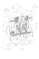
- FIG. 1 is a perspective view of a horizontal machining center according to an embodiment of the present invention as viewed from the front.
- FIG. 2 is a perspective view of the horizontal machining center of FIG. 1 viewed from the rear.
- FIG. 3 is a right side view of the horizontal machining center of FIG.
- FIG. 4 is a cross-sectional view of a clamp device that connects the first saddles of the horizontal machining center of FIG. 1.
- FIG. 5 is a front view showing a state in which an automatic tool changer is attached to the horizontal machining center of FIG. 6 is a right side view of the horizontal machining center of FIG.
- FIG. 7 is a block diagram showing a configuration for correcting the spindle interval.
- FIG. 8 is a flowchart showing the operation of the control device of FIG.
- FIG. 9 is a schematic diagram showing the principle of spindle interval correction.
- FIG. 10 is a perspective view of a horizontal machining center according to another embodiment of the present invention as seen from the rear.
- the horizontal machining center 1 of the present embodiment is a base column 10 and is attached to the base column 10 so as to be movable in the left-right direction.
- a spindle device 40 attached to the second saddle 30 so as to be movable in the front-rear direction.
- the first saddle 20 includes a first saddle 20a on the main side and a first saddle 20b on the sub side.
- the second saddle 30 also includes a main-side second saddle 30a and a sub-side second saddle 30b.
- the spindle device 40 includes a main spindle device 40a and a sub spindle device 40b.
- the main shaft 41 provided in the main shaft device 40 also includes a main-side main shaft 41a and a sub-side main shaft 41b.
- the main-side machining unit 100A includes a first saddle 20a, a second saddle 30a, and a spindle device 40a
- the sub-side machining unit 100B includes a first saddle 20b, a second saddle 30b, and a spindle device 40b.
- the processing units 100A and 100B are arranged in the left-right direction so that the main shafts 41a and 41b provided in the main shaft devices 40a and 40b are parallel to each other.
- the horizontal machining center 1 moves the spindle device 40 in the three axial directions of the left-right direction (X-axis direction), the vertical direction (Y-axis direction), and the front-back direction (X-axis direction), and uses a tool that rotates integrally with the spindle 41, Cutting the workpiece.
- the two spindles 41a and 41b each process one workpiece, each workpiece is the same, and the processing method is also the same.
- the base column 10 includes a base portion 11 and a gate-shaped column portion 12 provided thereon.
- the base part 11 and the column part 12 are integrally formed.
- the base part 11 is a lowermost part of the horizontal machining center 1 and is a part that is installed on the floor and fixes the machine.
- the base portion 11 has a base front portion 13 in front of the column portion 12 and a base rear portion 14 in the rear of the column portion 12 to enhance the stability of the machine. Further, since the base portion 11 and the column portion 12 form a single structure as the base column 10, rigidity is increased.
- the vertical thickness h of the base rear portion 14 is smaller than the vertical thickness H of the base front portion 13 (h ⁇ H).
- the base front portion 13 has a thickness necessary for maintaining the rigidity of the machine body when cutting a workpiece on a work table (not shown) placed on a jig stand 190 connected to the front surface thereof. H.
- the base rear part 14 has a thickness h smaller than the thickness H of the base front part 13 in order to lower the position of the first saddle 20 and other movable parts arranged on the upper surface thereof and lower the position of the center of gravity of the entire machine. have.
- the base front part 13 has a horizontal base part 13a.
- the horizontal base portion 13a is provided on the left side and the right side of the chip discharge portion 15 so that the rigidity of the machine body is secured.
- the horizontal platform 13a serves as a step for the operator during maintenance, and also serves as a space for placing tools and the like.
- the base rear portion 14 has a horizontal base portion 14a. As described above, the height of the upper surface of the horizontal base portion 14 a is lower than the height of the upper surface of the horizontal base portion 13 a of the base front portion 13.
- the chip front part 13 is provided with a chip discharge part 15.
- This chip discharge part 15 has the chute
- the column portion 12 includes a pair of column members 12a and 12a erected on the base portion 11, and an upper girder member 12b connecting the upper ends of these column members 12a and 12a.
- the column members 12a, 12a are arranged at a predetermined interval in the left-right direction, and are sufficient so that the two first saddles 20a, 20b guided in the left-right direction can move in the left-right direction within a range necessary for processing. Have an interval.
- the wall portion 12c guides the chips falling on the chip discharge portion 15 to the through holes 13c, prevents the chips from accumulating on the machine body, and connects the lower ends of the column members 12a and 12a. It also has a function as a girder member.
- a rectangular window 16 that opens in the front-rear direction is formed by the pair of column members 12a, 12a, the upper beam member 12b, and the wall portion 12c.
- an X-axis guide rail 58 of an X-axis guide mechanism 52G described later is fixed to the rear surface of the upper beam member 12b.
- a reference plane on which automatic tool changers 200 and 300 (see FIGS. 5 and 6), which will be described later, are attached to the front surface of the upper beam member 12b and the upper front surfaces of the column members 12a and 12a. 12d is provided in pairs of two.
- a plurality of reference surfaces 12d are provided, but a horizontally long single reference surface may be provided on the front surface or upper surface of the upper girder member 12b.
- the base column 10 is not limited to the above-described embodiment, and may be formed of, for example, separate base portions 11 and column portions 12. Further, the upper girder member 12b of the column portion 12 may be formed separately from the column member 12a and may be coupled to the column member 12a using a fixing member.
- the first saddle 20 (the first saddle 20a on the main side and the first saddle 20b on the sub side) is provided at the rear of the column portion 12, and is respectively in the left-right direction. It consists of a movable frame-shaped member.
- the first saddle 20a on the main side includes a pair of left and right column members 21a and 21a, an upper girder member 22a that connects the upper portions of the column members 21a and 21a, and a lower girder that connects the lower portions of the column members 21a and 21a.
- Member 23a By these members 21a to 23a, a vertically long window 24a (see FIG. 1) that opens in the front-rear direction is formed in the center of the first saddle 20a.
- the sub-side first saddle 20b is also configured in the same manner as the main-side first saddle 20a, and includes a column member 21b, an upper girder member 22b, a lower girder member 23b, and a rectangular window 24b.
- the rectangular window 16 of the column part 12 described above will be described in a little more detail.
- the rectangular window 16 has a vertical length equal to or longer than the vertical windows 24 (24a, 24b) of the first saddle 20 (20a, 20b), and is not shown in the figure.
- the window 16 and the vertically long window 24 overlap in the vertical direction.
- the lateral width of the rectangular window 16 is wider than the sum of the lateral widths of the two first saddles 20.
- the upper part of the 1st saddle 20 is supported by the rear surface of the upper girder member 12b of the column part 12 via the X-axis guide mechanism 52G mentioned later, and the lower part of the 1st saddle 20 via the X-axis guide mechanism 51G.
- the movable parts such as the first saddle 20 and the second saddle 30 described later are arranged behind the column part 12, the depth in the front-rear direction of the machine is shortened. Therefore, maintenance work for each of the moving mechanisms 50, 70, 80 described later can be easily performed from the rear of the machine.
- the clamp devices 90 (90-1 and 90-2) are provided at two locations, the upper part of the upper girder member 22 of the first saddle 20 and the lower part of the column member 21.
- the two first saddles 20a and 20b on the main side and the sub side are connected.
- FIG. 4 shows a cross-sectional view of the clamping device 90-1 provided at the lower part of the column member 21.
- a clamping device 90-1 is provided.
- the clamping device 90-1 includes a housing 91, a shaft 92, and a clamping sleeve 93.
- the housing 91 has a flange portion 91a and is inserted from the main-side hole 21aH to the sub-side hole 21bH.
- the clamping sleeve 93 is fitted into the housing 91 so that an annular space 94 is formed along the inner wall of the housing 91.
- the ring members 95 (95a, 95b) are provided to prevent the clamping sleeve 93 from moving in the left-right direction in FIG. 4 in the housing 91, and are screwed to the left and right of the housing 91, respectively.
- a part of the housing 91 is formed.
- the housing 91 is screwed to the inner wall of the main column member 21a with a flange portion 91a.
- the hollow shaft 92 has a cylindrical portion 92a and a flange portion 92b, and the cylindrical portion 92a is fitted into the clamping sleeve 93 from the sub-side hole 21bH.
- the horizontal length of the cylindrical portion 92 a is formed to be slightly longer than the horizontal length of the housing 91.
- the flange portion 92 b is screwed to the inner wall of the sub-side column member 21 b via the spacer 96.
- a plate 97 that is larger than the outer diameter of the cylindrical portion 92a and smaller than the outer diameter of the ring member 95a is screwed to the end portion of the cylindrical portion 92a so that the shaft 92 does not come out to the left.
- the plate 97 constitutes a part of the shaft 92.
- a hydraulic path 98 is provided in the main column member 21a.
- pressure is applied from the hydraulic passage 98 to the hydraulic fluid filling the annular space 94 through the annular groove 91b provided on the side surface of the housing 91 and the oil hole 91c formed in the housing 91, clamping is performed.
- the sleeve 93 presses the cylindrical portion 92 a and clamps the shaft 92.
- FIG. 4 shows that the shaft 92 is clamped in a state in which the gap 99a formed between the ring member 95a and the plate 97 is substantially equal to the gap 99b formed between the ring member 95b and the flange portion 92b. Indicates the state.
- the pressure on the hydraulic oil in the annular space 94 is lowered, the pressing force with which the clamping sleeve 93 presses the cylindrical portion 92a is weakened, and the shaft 92 is in an unclamped state where the clamp is released. In the unclamped state, the shaft 92 can move in the left-right direction within the housing 91 within the gaps 99a and 99b.
- clamping device 90-1 provided at the lower part of the column member 21, but a box-shaped frame member provided adjacent to the upper part of the upper girder members 22a and 22b shown in FIG.
- the clamping devices 90-2 in the 25a and 25b also have the same structure as the clamping device 90-1.
- the state where the main side first saddle 20a and the sub side first saddle 20b are connected is that the shafts 92 of the upper and lower two clamping devices 90-1 and 90-2 are both clamped.
- the main processing unit 100A and the sub processing unit 100B are integrally guided in the left-right direction. Further, when the shafts 92 of the two clamping devices 90-1 and 90-2 are simultaneously unclamped, the processing units 100A and 100B are disconnected.
- the X-axis moving mechanisms 51 and 52 are mechanisms for moving the first saddle 20 in the left-right direction.
- the main-side X-axis moving mechanism 52 is provided on the upper side.
- the sub-side X-axis moving mechanism 51 is provided on the lower side.
- These X-axis moving mechanisms 51 and 52 are known mechanisms and include X-axis guide mechanisms 51G and 52G and X-axis feed mechanisms 51Dr and 52Dr, respectively.
- the X-axis guide mechanism 51G provided in the X-axis moving mechanism 51 includes one X-axis guide rail 53 provided on the horizontal base portion 14a of the base rear portion 14 so as to extend in the left-right direction, and the first saddle on the main side.
- the X-axis feed mechanism 51Dr includes an X-axis drive motor 55 installed on the horizontal base portion 14a of the base rear portion 14, an X-axis ball screw 56 connected to the X-axis drive motor 55, and the X-axis ball screw 56. And a nut 57 that is screwed together.
- the nut 57 is fixed to the front surface of the lower girder member 23 b of the first saddle 20 b on the sub side, and the X-axis ball screw 56 is rotated by the X-axis drive motor 55.
- the X-axis guide mechanism 52G provided in the X-axis moving mechanism 52 includes one X-axis guide rail 58 provided on the rear surface of the upper girder member 12b of the column portion 12 so as to extend in the left-right direction, and the first saddle on the main side.
- 20a includes a pair of X-axis sliders 59a attached to the front surface of the upper girder member 22a, and a pair of X-axis sliders 59b attached to the front surface of the upper girder member 22b of the first saddle 20b on the sub side.
- the X-axis feed mechanism 52Dr includes an X-axis drive motor 60 installed on the upper surface of the upper beam member 12b of the column section 12, an X-axis ball screw 61 connected to the X-axis drive motor 60, and the X-axis ball screw. And a nut 62 screwed to 61.
- the nut 62 is fixed to the front surface of the box-shaped frame member 25a of the first saddle 20a on the main side, and rotates the X-axis ball screw 61 by the X-axis drive motor 60.
- each processing unit 100A, 100B includes independent X-axis moving mechanisms 52, 51, respectively.
- the above-described clamp device 90 connects the two first saddles 20a and 20b on the main side and the sub side, and guides them in the left-right direction as an integral structure.
- the first saddle 20 connected and integrated by the clamp device 90 has high rigidity.
- the X-axis drive motor 55 of the X-axis movement mechanism 51 and the X-axis drive motor 60 of the X-axis movement mechanism 52 are rotated in synchronization with each other, so that the first saddle 20 that is an integrated structure is driven in two ways. It can be moved in the left-right direction along the X-axis guide rails 53, 58 in a state where it is more powerful and stable by the source.
- the X-axis drive motors 55 and 60 of the X-axis moving mechanisms 51 and 52 are installed so as to be located on the same side (sub-side). , 61 have the same rotation direction.
- the X-axis feed mechanisms 51Dr and 52Dr are arranged so as to be located on substantially the same vertical line. This arrangement has a very good balance when the main shaft device 40 is guided in the vertical direction (Y-axis direction) and the front-rear direction (Z-axis direction), and gives a sense of stability to the machine.
- the second saddle 30 is supported by the first saddle 20 so as to be movable in the vertical direction.
- the second saddle 30a on the main side is supported by the first saddle 20a on the main side so as to be movable in the vertical direction, and the second saddle 30b on the sub side moves in the vertical direction on the first saddle 20b on the sub side.
- the second saddle 30a on the main side is made of a cylindrical member that holds the spindle device 40a, and a flange portion 31a provided with a Y-axis slider 72a, which will be described later, provided on the back surface, a Z-axis moving mechanism 80a, and the spindle device 40a, which will be described later.
- the second saddle 30a is supported by the first saddle 20a via a Y-axis guide mechanism 70aG provided between the flange portion 31a and the pair of left and right column members 21a of the first saddle 20a. It moves in the vertical direction in the vertical window 24a of the saddle 20a.
- the sub-side second saddle 30b also has the same structure as the main-side second saddle 30a.
- the Y-axis moving mechanism 70 is a mechanism for moving the second saddle 30 in the vertical direction, and includes a Y-axis guide mechanism 70G and a Y-axis feed mechanism 70Dr.
- the main-side Y-axis movement mechanism 70a includes a Y-axis guide mechanism 70aG and a Y-axis feed mechanism 70aDr, and moves the main-side second saddle 30a in the vertical direction.
- the sub-side Y-axis moving mechanism 70b includes a Y-axis guide mechanism 70bG and a Y-axis feed mechanism 70bDr, and moves the sub-side second saddle 30b in the vertical direction.
- the main-side Y-axis guide mechanism 70aG includes a pair of Y-axis guide rails 71a provided in front of the pair of left and right column members 21a of the main-side first saddle 20a so as to extend in the vertical direction, and each Y-axis guide.
- the Y-axis slider 72a is fitted to the rail 71a and provided on the left and right rear surfaces of the flange portion 31a of the second saddle 30a on the main side.
- the main-side Y-axis feed mechanism 70aDr includes a Y-axis drive motor 73a attached to the upper surface of the upper girder member 22a of the main-side first saddle 20a, a Y-axis ball screw 74a connected to the Y-axis drive motor 73a, And a nut 75a screwed into the Y-axis ball screw 74a.
- the nut 75a is fixed to the holding portion 32a of the second saddle 30a on the main side.
- the sub-side Y-axis moving mechanism 70b has the same configuration as the main-side Y-axis moving mechanism 70a.
- the Y-axis drive motor 73a provided in the main-side Y-axis feed mechanism 70aDr and the Y-axis drive motor 73b provided in the sub-side Y-axis feed mechanism 70bDr may be rotated in synchronization with each other. It may be rotated.
- the Y-axis ball screws 74a and 74b rotate, and the second saddles 30a and 30b move in the vertical direction along the Y-axis guide rails 71a and 71b, respectively.
- the Y-axis moving mechanism 70 is a known mechanism.
- the Y-axis guide rails 71a and 71b of the Y-axis guide mechanism 70G are as shown in FIG. It is provided vertically between the upper part. That is, the X-axis guide mechanism 52G and the Y-axis guide mechanism 70G are substantially located on the same plane (XY plane).
- Main shaft device The main shaft device 40 is supported by the second saddle 30 and includes a main shaft 41 and a main shaft housing 42.
- the main spindle device 40a is supported by the second saddle 30a on the main side, and includes a spindle 41a and a spindle housing 42a.
- the sub-side main shaft device 40b is supported by the sub-side second saddle 30b, and includes a main shaft 41b and a main shaft housing 42b.
- the main shaft 41a of the main-side main shaft device 40a is held in the main shaft housing 42a so as to be rotatable about the Z axis.
- the main shaft 41a is connected to a rotation shaft of a main shaft drive motor (not shown) built in the main shaft housing 42a, and various tools (not shown) are detachably attached to the front end portion of the main shaft 41a.
- a Z-axis guide rail (not shown) of a main-side Z-axis guide mechanism (not shown), which will be described later, is attached to the lower surface of the spindle housing 42a in the front-rear direction.
- the spindle device 40a is held in the flange portion 31a and the holding portion 32a of the second saddle 30a on the main side so as to be movable in the front-rear direction via the Z-axis guide mechanism.
- the spindle device 40a is movable in the vertical direction and the front-rear direction in the vertically long window 24a of the first saddle 20a, and in the left-right direction, the vertical direction, and the front-rear direction in the rectangular window 16 of the column portion 12. It is movable.
- the vertical length of the rectangular window 16 is longer than the vertical stroke of the main shaft 41a.
- the sub-side spindle device 40b has the same configuration as the main-side spindle device 40a described above.
- the Z-axis moving mechanism 80 is a mechanism for moving the spindle device 40 in the front-rear direction, and includes a known Z-axis guide mechanism 80G and a Z-axis feed mechanism 80Dr.
- the main-side Z-axis movement mechanism 80a includes a Z-axis guide mechanism (not shown) and a Z-axis feed mechanism 80aDr
- the sub-side Z-axis movement mechanism 80b includes a Z-axis guide mechanism 80bG.
- a Z-axis feed mechanism 80bDr a Z-axis feed mechanism 80bDr.
- the sub-side Z-axis moving mechanism 80b will be described.
- the Z-axis guide mechanism 80bG of the sub-side Z-axis moving mechanism 80b includes a Z-axis guide rail 81b attached to the lower surface of the main shaft housing 42b so as to extend in the front-rear direction, and a second saddle 30b.
- the Z-axis feed mechanism 80bDr on the sub side includes a Z-axis drive motor 83b attached so as to protrude rearward of the holding portion 32b of the second saddle 30b, and a Z-axis ball screw 84b connected to the Z-axis drive motor 83b.
- the main-side Z-axis moving mechanism 80a has the same configuration as the sub-side Z-axis moving mechanism 80b described above.
- the number and location of the Z-axis sliders 82b provided on the sub-side second saddle 30b can be arbitrarily selected according to the number and location of the Z-axis guide rails 81b. The same applies to the Z-axis moving mechanism 80a on the main side.
- FIG. 3 shows a state in which a jig table 190 is arranged in front of the horizontal machining center 1.
- the jig base 190 is a structure that is attached to the front surface of the base front portion 13 of the base column 10 and is fixed to the floor surface.
- the horizontal width and the vertical height of the jig base 190 are the same as the horizontal width and the vertical height of the base front portion 13.
- an A-axis table (not shown) is placed on the jig stand 190.
- the jig table 190 is provided with a chip discharge portion (not shown) similar to the chip discharge portion 15 provided in the base front portion 13.
- This chip discharging part has a chute (not shown) and a through hole (not shown). Chips generated at the time of workpiece processing fall on the chute and are guided to the through hole, and are discharged from the through hole to a chip conveyor (not shown) installed under the jig base 190.
- a chip conveyor not shown
- the jig base 190 is provided with horizontal base parts 191 on both the left and right sides of the chip discharging part, similarly to the horizontal base part 13a of the base front part 13.
- a mounting table 192 is provided on the upper surface of each horizontal table 191, and a driving unit and a support unit (not shown) of the A-axis table are mounted on each mounting table 192.
- the jig table 190 on which the A-axis table is placed is taken as an example, but the B-axis table may be placed on the jig table 190. Also, a jig changer specification jig stand or a pallet changer specification jig stand may be provided. Further, the chip discharge portion may be omitted, and the chips may be discharged to the chip discharge portion 15 of the base front portion 13.
- each jig corresponds to the main-side main shaft 41a and the sub-side main shaft 41b.
- a reference hole for position measurement is provided at the location. This reference hole is necessary to correct the distance between the main shafts 41a and 41b. The correction of the main shaft distance will be described in detail later.
- FIG. 5 shows an automatic tool changer (hereinafter referred to as “ATC unit”) 200 on a reference surface 12d (see FIG. 1) provided on the front surface of the upper beam member 12b of the column portion 12. The state where 300 is attached is shown.
- ATC unit automatic tool changer
- the main ATC unit 200 includes a large number of tool holding members 202 at the periphery of a frame 201 having a substantially trapezoidal shape.
- These tool holding members 202 include a connecting portion for connecting the tool holding members by a link mechanism (not shown) such as a chain, and a tool for moving the connected tool holding members along the periphery of the frame 201. It consists of a cam follower part (not shown) constituting a part of the cam mechanism and a claw part 204 for gripping the tool 203.
- a tool holding member 202 that holds the tool 203 to be held by the main spindle 41a is positioned at a tool change position described later by a motor (not shown).
- a so-called direct change method in which the tools 203 and 303 are directly transferred between the ATC units 200 and 300 and the spindles 41a and 41b is adopted as the automatic tool change method.
- the frame 201 has a substantially trapezoidal shape and is composed of five sides 201a to 201e.
- the two parallel sides 201a and 201b are arranged so as to be vertical in a front view. Of these two sides, the short side 201a is on the outer side of the machine, and the long side 201b is on the inner side of the machine.
- the horizontal side 201c is perpendicular to the above two sides, and the inclined side 201d is inclined so as to approach the main shaft 41a from the outer side to the inner side of the machine.
- the horizontal side 201e is above the spindle housing 42a and has a length that is substantially the same as the width in the left-right direction of the spindle housing 42a.
- the horizontal side 201e is opposed to the main shaft 41a, and the tool 203 held by the tool holding member 202 positioned substantially at the center of the horizontal side 201e is held by the main shaft 41a.
- the tool holding unit 202 has a known structure and includes a claw portion 204 including two claws that hold the tool 203.
- the claw portion 204 takes a downward vertical posture on the horizontal side 201 e of the frame 201 and grips the tool 203.
- the frame 201 is held by a holding member 205 and a bracket 206 on the back side. Therefore, the ATC unit 200 is fixed not only to the reference surface 12d of the column portion 12 but also to the upper surface of the upper girder member 12b, and is stably attached to the base column 10.
- the sub-side ATC unit 300 includes a frame 301 that is symmetrical to the main-side frame 201 and has the same configuration as the main-side ATC unit 200.
- the reference surface 12d is provided on the upper front surface of the column portion 12, it is only necessary to attach the ATC units 200 and 300 assembled in advance to the reference surface 12d. Further, since the frames 201 and 301 have inclined sides 201d and 301d that are inclined so as to approach the main shafts 41a and 41b from the outside to the inside of the machine, there is nothing to block the front surface of the column member 12a of the column portion 12. . For this reason, for example, a dispensing device for dispensing a tool with a broken blade can be provided on the front surface of the column member 12a, and the space can be used effectively.
- FIG. 7 shows a configuration for correcting the spindle interval.
- the control device 5 includes a CPU 5a, a storage unit 5b, a motor control unit 5c, and a clamp drive unit 5g. In addition to these, the control device 5 includes blocks for performing various processes, but only the blocks related to correction are shown here.
- the CPU 5a is composed of a microprocessor, and controls the overall operation of the machine tool (horizontal machining center 1). This operation includes an operation for correcting the spindle interval in addition to a normal operation for machining a workpiece.
- a storage unit 5b, a motor control unit 5c, a clamp drive unit 5g, and a reference position measuring device 6 are connected to the CPU 5a, and signals and data are exchanged between the CPU 5a and these units.
- the storage unit 5b includes a program memory in which a program necessary for control performed by the CPU 5a is stored, a data memory in which data necessary for control is stored (not illustrated), and the like.
- the motor control unit 5c includes an X-axis motor control unit 5d, a Y-axis motor control unit 5e, and a Z-axis motor control unit 5f.
- the X-axis motor control unit 5d controls the X-axis drive motor 60 provided in the main-side X-axis feed mechanism 52Dr and the X-axis drive motor 55 provided in the sub-side X-axis feed mechanism 51Dr.
- the Y-axis motor control unit 5e controls the Y-axis drive motor 73a provided in the main-side Y-axis feed mechanism 70aDr and the Y-axis drive motor 73b provided in the sub-side Y-axis feed mechanism 70bDr.
- the Z-axis motor control unit 5f controls the Z-axis drive motor 83a provided in the main-side Z-axis feed mechanism 80aDr and the Z-axis drive motor 83b provided in the sub-side Z-axis feed mechanism 80bDr.
- the clamp drive unit 5g includes a drive circuit that drives the hydraulic device 7 that applies pressure to the hydraulic oil in the annular space 94 (FIG. 4) of the clamp device 90.
- the reference position measuring device 6 includes touch probes 6a and 6b attached to the tips of the main shafts 41a and 41b on the main side and the sub side.
- the touch probes 6a and 6b detect the positions of the reference holes 9a and 9b provided in the jigs 8a and 8b, and the CPU 5a corrects the interval between the main shafts 41a and 41b based on the detection result.
- FIG. 8 is a flowchart showing a procedure for correcting the spindle interval. This procedure is executed by the CPU 5a according to the spindle interval correction program stored in the storage unit 5b. Hereinafter, the procedure for correcting the spindle interval will be described in detail according to the flowchart.
- step S1 the touch probes 6a and 6b are attached to the tip of the main spindle 41a and the tip of the sub spindle 41b.
- the touch probes 6a and 6b before being attached are held together with the tools in the ATC units 200 and 300, and are automatically attached to the tips of the main shafts 41a and 41b by operating the ATC units 200 and 300.
- step S2 the main-side main shaft 41a comes to the position of the reference hole 9a provided in the main-side jig 8a, that is, the X-coordinate and Y-coordinate of the main shaft 41a are the X-coordinate and Y-axis of the reference hole 9a.
- the spindle device 40a is moved in the X-axis direction and the Y-axis direction by the X-axis feed mechanism 52Dr and the Y-axis feed mechanism 70aDr so as to coincide with the coordinates.
- FIG. 9 shows this state, and the center line Pa of the main spindle 41a coincides with the center line Qa of the reference hole 9a of the main jig 8a.
- step S3 the main spindle device 40a and the sub spindle device 40b are advanced by a certain distance in the Z-axis direction by the Z-axis feed mechanisms 80aDr and 80bDr, respectively. Thereby, the touch probes 6a and 6b attached to the tips of the main shafts 41a and 41b enter the reference holes 9a and 9b, respectively.
- step S4 the positions (X coordinate, Y coordinate) of the reference holes 9a, 9b are measured by the touch probes 6a, 6b. Specifically, while moving the spindle devices 40a and 40b in the X-axis direction and the Y-axis direction, the touch probes 6a and 6b are brought into contact with a plurality of locations (for example, 4 locations) on the inner walls of the reference holes 9a and 9b. Based on the X and Y coordinates of the position, the X and Y coordinates of the center lines Qa and Qb of the reference holes 9a and 9b are obtained. The X coordinate and the Y coordinate at this time are the positions of the reference holes 9a and 9b, and these positions are reference positions that serve as a reference for correcting the spindle interval.
- step S5 the spindle devices 40a and 40b are moved back in the Z-axis direction by the Z-axis feed mechanisms 80aDr and 80bDr, respectively. Thereby, the touch probes 6a and 6b come out of the reference holes 9a and 9b.
- step S6 based on the positions of the reference holes 9a and 9b measured in step S4, the interval between the reference holes 9a and 9b, that is, the reference hole interval W1 in FIG. 9 is calculated.
- the reference hole interval W1 can be calculated as the difference between the X coordinate of the center line Qa of the reference hole 9a and the X coordinate of the center line Qb of the reference hole 9b.
- step S7 the interval between the spindles 41a and 41b, that is, the spindle interval W2 in FIG. 9 is read from the storage unit 5b.
- the storage unit 5b stores correction data such as the reference hole interval W1 and the spindle interval W2. Accordingly, the spindle interval W2 read in step S7 is the previously corrected spindle interval.
- This difference ⁇ W is a correction amount for correcting the spindle interval W2.
- the difference ⁇ W may be compared with a predetermined threshold value ⁇ , and if ⁇ W ⁇ , it may be determined that there is no error, and if ⁇ W ⁇ ⁇ , it may be determined that there is an error.
- step S9 if there is an error in the spindle interval W2 (step S9; YES), the process proceeds to step S10. If there is no error in the spindle interval W2 (step S9; NO), the procedure after step S10 is executed. The process is terminated without
- step S10 the clamping device 90 is placed in an unclamped state, and the connection between the main side and the sub-side first saddles 20a and 20b is released.
- the sub-side first saddle 20b is separated from the main-side first saddle 20a and can move independently in the X-axis direction (left-right direction).
- step S11 the X-axis drive motor 55 of the sub-side X-axis feed mechanism 51Dr is rotated so that the entire machining unit 100B including the sub-side first saddle 20b is X by the correction amount ⁇ W calculated in step S8. Move in the axial direction.
- the main shaft 41b moves to the left by ⁇ W, and the center line Pb of the main shaft 41b matches the center line Qb of the reference hole 9b.
- the spindle interval W2 becomes equal to the reference hole interval W1, and the correction of the spindle interval W2 is completed.
- step S12 the clamp device 90 is again clamped to connect the first saddles 20a and 20b on the main side and the sub side.
- the spindles 41a and 41b are in a reset state in which the error of the spindle interval W2 is eliminated. Since the first saddles 20a and 20b are connected to increase the rigidity, it is preferable to connect the two saddles after the correction is completed as described above in the case of machining that requires the rigidity of the saddle. Is not always necessary.
- the first saddles 20a and 20b are synchronized by the X-axis drive motors 60 and 55 of the X-axis moving mechanisms 52 and 51, respectively, while the clamp device 90 remains in the unclamped state after the correction is completed. And may be moved.
- the control device 5 After correcting the spindle interval in this way, the control device 5 sends the corrected position data (X coordinate, Y coordinate) of the spindles 41a and 41b to the ATC units 200 and 300. This is because the tool change position in the ATC units 200 and 300 needs to be adjusted in accordance with the correction of the spindle interval. Based on this position data, the ATC units 200 and 300 drive motors (not shown) provided in each unit to adjust the tool change positions of the tool holding units 202 and 302. Thereby, the tool exchange performed between the main shafts 41a and 41b can be performed accurately and quickly.
- the spindles 41a and 41b with the corrected spindle interval W2 are used in the Y-axis direction and the Z-axis direction in order to replace the touch probes 6a and 6b attached to their tips with the tools 203 and 303 necessary for processing the workpiece. It is moved to the tool change position. At this time, on the ATC units 200 and 300 side, the tool holders 202 and 302 that hold the tools 203 and 303 necessary for processing the workpiece move to a tool change position in the X-axis direction by a motor and a cam mechanism (not shown). .
- the tool change positions of the ATC units 200 and 300 are substantially the center positions of the horizontal sides 201e and 301e of the frames 201 and 301. For this reason, even when finely adjusting the positions of the tool holders 202 and 302 on the horizontal sides 201e and 301e in the X-axis direction, the claw portions 204 and 304 maintain a posture that is orthogonal to the horizontal sides 201e and 301e. Therefore, tool exchange between the main shafts 41a and 41b is performed smoothly.
- the spindle intervals of the spindle devices 40a and 40b are corrected as described above, when machining a workpiece, the main-side machining unit 100A and the sub-side machining unit 100B move together in the X-axis direction. Therefore, the spindle interval is stably maintained, and the workpiece can be processed with high accuracy.
- the X-axis moving mechanisms 52 and 51 are provided corresponding to the processing units 100A and 100B, respectively.
- the processing unit 100B is moved in the left-right direction (X-axis direction) together with the first saddle 20b by the drive motor 55 to adjust the position of the main shaft 41b.
- the X-axis moving mechanism 51 does not operate only when the spindle interval is corrected, but also operates during normal workpiece machining. Accordingly, the spindle distance can be corrected by using the existing X-axis moving mechanism 51 without providing a dedicated device for correcting the spindle distance, so that the workpiece can be processed with high accuracy with a simple configuration. Can do. Further, since it is not necessary to perform complicated fine adjustment manually, there is a great merit in terms of time and cost.
- the sub-side machining unit 100B when correcting the spindle interval, is moved by the X-axis moving mechanism 51, but the main-side machining unit 100A is moved by the X-axis moving mechanism 52. It may be moved. Further, both the main-side and sub-side processing units 100A, 100B may be moved by both the X-axis moving mechanisms 51, 52.
- the second saddles 30a and 30b are moved in the vertical direction (Y-axis direction) by the main-side and sub-side Y-axis moving mechanisms 70a and 70b.
- the vertical displacement of the main shafts 41a and 41b can be corrected.
- the main-side and sub-side Z-axis moving mechanisms 80a and 80b are moved in the front-rear direction (Z-axis direction), so that the spindles 41a and 41b between the machining units 100A and 100B are moved.
- the deviation in the front-rear direction can be corrected.
- the present embodiment not only the horizontal position correction of the main shafts 41a and 41b, but also the vertical position correction and the front-back position correction can be performed.
- the positions of the main shafts 41a and 41b can be corrected for all three axes of X, Y, and Z.
- the stacking order of the moving mechanisms of the X, Y, and Z axes provided in the processing units 100A and 100B installed on the base portion 11 is X ⁇ Y ⁇ Z from the bottom. It has become. That is, for example, in the processing unit 100A, when the first saddle 20a is moved in the left-right direction (X-axis direction) by the X-axis moving mechanism 52, the Y-axis moving mechanism 70a provided in the first saddle 20a is also moved in the left-right direction. Furthermore, the Z-axis moving mechanism 80a provided on the second saddle 30a held by the first saddle 20a also moves in the left-right direction.
- the Y-axis moving mechanism 70a is always moved in the left-right direction, and the Y-axis moving mechanism 70a is always moved in the left-right direction.
- the axis moving mechanism 80a is also moved in the left-right direction in the stacking order of X ⁇ Y ⁇ Z.
- the stacking order of the moving mechanism of each axis is, for example, Y ⁇ X ⁇ Z from the bottom.
- a central column for installing a Y-axis guide rail between the left and right column members 12a and 12a of the column portion 12 of the present embodiment The member is absolutely necessary, and the entire machine becomes large.
- the two processing units 100A and 100B are guided on the common X-axis guide rails 58 and 53. In the case of order, it is necessary to provide a guide rail for each of the processing units 100A and 100B.
- the stacking order of the moving mechanisms of the respective axes is set as X ⁇ Y ⁇ Z as in the present embodiment, a central column member is provided between the left and right column members 12a, 12a of the column portion 12, or each processing unit It is not necessary to provide a guide rail for each of 100A and 100B. For this reason, it can be said that the stacking order in the present embodiment greatly contributes to miniaturization of the machine even when the positions of the two main shafts 41a and 41b are corrected in all three axial directions.
- the X-axis moving mechanism 52 corresponding to the first saddle 20a of the main processing unit 100A is provided at the upper portion of the column portion 12, and the sub processing is performed.
- the X-axis moving mechanism 51 corresponding to the first saddle 20b of the unit 100B is provided on the upper surface of the base portion 11. For this reason, in a state where the processing units 100A and 100B are connected by the clamp device 90, the entire processing unit is stably supported by the X-axis moving mechanisms 52 and 51 on the upper side and the lower side.
- the X-axis moving mechanism 52 corresponding to the first saddle 20 a of the main processing unit 100 ⁇ / b> A is provided at the top of the column portion 12.
- the X-axis moving mechanism 51 corresponding to the first saddle 20b of the sub-side processing unit 100B is provided on the upper surface of the base portion 11.
- the first saddle 20 is disposed on the upper surface of the thin base rear portion 14, the first saddle 20, the second saddle 30 supported by the first saddle 20, and the second saddle.
- Each position of the spindle device 40 supported by 30 can be lowered. For this reason, the center of gravity of the entire machine is lowered and stability is improved.
- the rectangular window 16 of the column portion 12 has a vertical length equal to or longer than the vertical window 24 of the first saddle 20, and the rectangular window 16 and the vertical window 24 overlap each other. The lowest end position of 41 is lowered. Therefore, even if there is no step, it is possible to detach the workpiece, inspect the tip of the spindle 41, inspect the tool, and the like.
- the first saddle 20 is disposed on the thin base rear portion 14, the overall height of the machine can be suppressed, and the machine can be further downsized in combination with the shortening of the depth described above. . Moreover, even if the machine becomes compact, the strokes of the main shaft 41 in the X-axis direction, the Y-axis direction, and the Z-axis direction are not reduced compared to the conventional one.
- the X-axis guide rail 58 is installed on the rear surface of the upper beam member 12 b of the column portion 12, and the Y-axis guide rail 71 is installed on the front surface of the column members 21, 21 of the first saddle 20. It is installed. Therefore, the X-axis guide mechanism 52G and the Y-axis guide mechanism 70G are located between substantially the same plane (XY plane) between the rear surface of the upper girder member 12b of the column portion 12 and the front surface of the first saddle 20. .
- FIG. 10 shows another embodiment of a horizontal machining center. 10 is different from FIG. 2 in that the main-side X-axis feed mechanism 52Dr in FIG. In FIG. 10, only the drive motor 60 of the X-axis feed mechanism appears, and the ball screw 61 and the nut 62 of FIG. 2 do not appear. According to this embodiment, since the X-axis feed mechanism does not exist on the upper surface of the base column 10, the height of the machine can be kept low correspondingly. Further, a tool magazine of the ATC unit can be easily installed on the upper surface of the base column 10.
- the touch probes 6a and 6b are used to measure the positions of the reference holes 9a and 9b, but it goes without saying that sensors other than the touch probes may be used.
- the reference holes 9a and 9b are provided in the jigs 8a and 8b.
- the reference holes may be provided in a member other than the jig.
- the reference position is not limited to the hole but may be a groove or a protrusion.
- the previous spindle interval W2 stored in the storage unit 5b is read in step S7 of FIG. 8, but instead, when the positions of the reference holes 9a and 9b are measured in step S4.
- the positions of the spindles 41a and 41b may be measured simultaneously, and the spindle interval W2 may be calculated from these positions.
- the processing units 100A and 100B can be moved independently without connecting the first saddles 20a and 20b so that the strokes of the first saddles 20a and 20b in the X-axis direction do not interfere with each other. It is sufficient to process each workpiece.
- the machine tool provided with the two main shafts 41a and 41b has been described as an example, but the present invention can be similarly applied to a machine tool provided with three or more main shafts.
- the machining center is exemplified as the machine tool, but the present invention can also be applied to machine tools other than the machining center.
Landscapes
- Engineering & Computer Science (AREA)
- Mechanical Engineering (AREA)
- Human Computer Interaction (AREA)
- Manufacturing & Machinery (AREA)
- Physics & Mathematics (AREA)
- General Physics & Mathematics (AREA)
- Automation & Control Theory (AREA)
- Machine Tool Units (AREA)
- Automatic Control Of Machine Tools (AREA)
- Automatic Tool Replacement In Machine Tools (AREA)
- Numerical Control (AREA)
Abstract
Description
図1および図2に示すように、本実施形態の横型マシニングセンタ1は、ベースコラム10と、このベースコラム10に対して、左右方向に移動可能に取り付けられた第1サドル20と、この第1サドル20に対して、上下方向に移動可能に取り付けられた第2サドル30と、この第2サドル30に対して、前後方向に移動可能に取り付けられた主軸装置40とを備えている。
ベースコラム10は、ベース部11と、その上に設けられた門形のコラム部12とからなる。ここでは、ベース部11とコラム部12とは、一体的に形成されている。ベース部11は、横型マシニングセンタ1の最下部にあって、床面に据え付けられて機械を固定する部位である。このベース部11は、コラム部12の前方にベース前部13、コラム部12の後方にベース後部14をそれぞれ有していて、機械の安定性を高めている。また、ベース部11とコラム部12が、ベースコラム10として単一の構造体をなしていることで、剛性を高めている。
図2に示すように、第1サドル20(メイン側の第1サドル20aと、サブ側の第1サドル20b)は、コラム部12の後方に設けられ、それぞれ左右方向へ移動可能な枠状の部材からなる。詳しくは、メイン側の第1サドル20aは、左右一対の柱部材21a、21aと、柱部材21a、21aの上部を連結する上桁部材22aと、柱部材21a、21aの下部を連結する下桁部材23aとを有している。これらの各部材21a~23aによって、第1サドル20aの中央に、前後方向に開口する縦長の窓24a(図1参照)が形成されている。サブ側の第1サドル20bも、メイン側の第1サドル20aと同様に構成されており、柱部材21b、上桁部材22b、下桁部材23b、および方形窓24bを有している。
次に、メイン側の第1サドル20aとサブ側の第1サドル20bとを連結するクランプ装置90について説明する。
X軸移動機構51、52は、第1サドル20を左右方向に移動させるための機構であり、本実施形態では、メイン側のX軸移動機構52は上側に設けられ、サブ側のX軸移動機構51は下側に設けられている。これらのX軸移動機構51、52は公知の機構であり、それぞれX軸ガイド機構51G、52Gと、X軸送り機構51Dr、52Drを備えている。
第2サドル30は、第1サドル20に上下方向へ移動可能に支持されている。詳しくは、メイン側の第2サドル30aは、メイン側の第1サドル20aに上下方向へ移動可能に支持され、サブ側の第2サドル30bは、サブ側の第1サドル20bに上下方向へ移動可能に支持されている。メイン側の第2サドル30aは、主軸装置40aを保持する筒状の部材からなり、後述するY軸スライダ72aが背面に設けられたフランジ部31aと、後述するZ軸移動機構80aおよび主軸装置40aを収納する保持部32aとを備えている。この第2サドル30aは、フランジ部31aと第1サドル20aの左右一対の柱部材21aとの間に設けられたY軸ガイド機構70aGを介して、第1サドル20aに支持されており、第1サドル20aの縦長窓24a内を上下方向に移動する。サブ側の第2サドル30bも、上述したメイン側の第2サドル30aと同様の構造を有している。
Y軸移動機構70は、第2サドル30を上下方向に移動させるための機構であり、Y軸ガイド機構70Gと、Y軸送り機構70Drとを備えている。詳しくは、メイン側のY軸移動機構70aは、Y軸ガイド機構70aGと、Y軸送り機構70aDrとを備えており、メイン側の第2サドル30aを上下方向に移動させる。サブ側のY軸移動機構70bは、Y軸ガイド機構70bGと、Y軸送り機構70bDrとを備えており、サブ側の第2サドル30bを上下方向に移動させる。
主軸装置40は、第2サドル30に支持されており、主軸41と主軸ハウジング42とを備えている。詳しくは、メイン側の主軸装置40aは、メイン側の第2サドル30aに支持されており、主軸41aと主軸ハウジング42aとを備えている。サブ側の主軸装置40bは、サブ側の第2サドル30bに支持されており、主軸41bと主軸ハウジング42bとを備えている。
Z軸移動機構80は、主軸装置40を前後方向に移動させるための機構であり、公知のZ軸ガイド機構80GおよびZ軸送り機構80Drを備えている。詳しくは、メイン側のZ軸移動機構80aは、Z軸ガイド機構(図示省略)と、Z軸送り機構80aDrとを備えており、サブ側のZ軸移動機構80bは、Z軸ガイド機構80bGと、Z軸送り機構80bDrとを備えている。以下では、サブ側のZ軸移動機構80bについて説明する。
図3は、横型マシニングセンタ1の前方に冶具台190を配置した状態を示している。この冶具台190は、ベースコラム10のベース前部13の前面に取り付けられ、床面に固定される構造体である。冶具台190の左右方向の幅および上下方向の高さは、ベース前部13の左右方向の幅および上下方向の高さと同じである。冶具台190には、例えばA軸テーブル(図示省略)が載置される。
図5は、コラム部12の上桁部材12bの前面に設けられた基準面12d(図1参照)に、自動工具交換装置(以下「ATCユニット」と表記)200、300を取り付けた状態を示している。
冒頭に述べたように、複数の主軸を備えた工作機械においては、温度変化やワーク加工時に発生する熱などが原因で、主軸間隔に変位が生じて加工精度が低下するため、主軸間隔の補正が必要となる。以下、この補正について詳細に説明する。
上述した実施形態では、図2に示されるように、メイン側の加工ユニット100Aの第1サドル20aに対応するX軸移動機構52は、コラム部12の上部に設けられ、サブ側の加工ユニット100Bの第1サドル20bに対応するX軸移動機構51は、ベース部11の上面に設けられている。このため、加工ユニット100A、100Bがクランプ装置90で連結された状態では、加工ユニット全体が上側と下側において、X軸移動機構52、51により安定して支持されることになる。
(14)他の実施形態
5 制御装置
6 基準位置測定器
6a、6b タッチプローブ
9a、9b 基準孔
20a、20b 第1サドル
30a、30b 第2サドル
40a、40b 主軸装置
41a、41b 主軸
51、52 X軸移動機構
70 Y軸移動機構
80 Z軸移動機構
90 クランプ装置
100A、100B 加工ユニット
200、300 ATCユニット(自動工具交換装置)
Claims (7)
- 左右方向へ移動可能な第1サドルと、この第1サドルに支持され上下方向へ移動可能な第2サドルと、この第2サドルに支持され前後方向へ移動可能な主軸装置と、を含む加工ユニットが複数設けられ、
各加工ユニットが、それぞれの主軸装置に備わる主軸が平行となるように、左右方向に配列された工作機械において、
前記第1サドルを左右方向へ移動させるX軸移動機構と、
ワークの加工時および加工ユニット相互間の主軸間隔の補正時に、前記X軸移動機構の動作を制御する制御装置と、を備え、
前記X軸移動機構は、複数の加工ユニットのそれぞれに対応して設けられており、
前記制御装置は、主軸間隔の補正時に、所定の加工ユニットの第1サドルを、当該加工ユニットに対応するX軸移動機構により左右方向へ移動させて主軸間隔を補正する、ことを特徴とする工作機械。 - 請求項1に記載の工作機械において、
主軸間隔の補正の基準となる基準位置を測定する基準位置測定器をさらに備え、
前記制御装置は、主軸間隔の補正時に、前記基準位置測定器が測定した基準位置に基づいて補正量を算出し、前記第1サドルを前記補正量だけ左右方向へ移動させるように前記X軸移動機構を制御する、ことを特徴とする工作機械。 - 請求項1または請求項2に記載の工作機械において、
隣接する2つの加工ユニットの第1サドル同士を連結するクランプ装置をさらに備え、
前記制御装置は、
主軸間隔の補正時に、前記クランプ装置をアンクランプ状態にして、前記第1サドル同士の連結を解除し、
主軸間隔の補正が終了すると、前記クランプ装置をクランプ状態にして、前記第1サドル同士を連結するか、または、前記クランプ装置をアンクランプ状態のままにして、前記2つの加工ユニットのそれぞれに対応するX軸移動機構により、前記第1サドル同士を同期して移動させる、ことを特徴とする工作機械。 - 請求項1ないし請求項3のいずれかに記載の工作機械において、
前記制御装置は、
隣接する2つの加工ユニットのうち、一方の加工ユニットの第1サドルを左右方向へ移動しないように固定した状態で、他方の加工ユニットの第1サドルを左右方向へ移動させて主軸間隔を補正する、ことを特徴とする工作機械。 - 請求項1ないし請求項4のいずれかに記載の工作機械において、
各加工ユニットの第2サドルを上下方向へ移動させるY軸移動機構と、
各加工ユニットの主軸装置を前後方向へ移動させるZ軸移動機構と、をさらに備え、
前記Y軸移動機構および前記Z軸移動機構は、複数の加工ユニットのそれぞれに対応して設けられており、
前記制御装置は、
前記Y軸移動機構により前記第2サドルを上下方向へ移動させて、加工ユニット相互間における主軸の上下方向のずれを補正し、
前記Z軸移動機構により前記主軸装置を前後方向へ移動させて、加工ユニット相互間における主軸の前後方向のずれを補正する、ことを特徴とする工作機械。 - 請求項1ないし請求項5のいずれかに記載の工作機械において、
各加工ユニットの主軸に取り付けられた工具を交換する自動工具交換装置をさらに備え、
前記制御装置は、補正された主軸の位置データを前記自動工具交換装置へ送る、ことを特徴とする工作機械。 - 請求項6に記載の工作機械において、
前記自動工具交換装置は、工具を収容するフレームを備え、
前記フレームは、前記主軸と対向する水平辺を有している、ことを特徴とする工作機械。
Priority Applications (5)
| Application Number | Priority Date | Filing Date | Title |
|---|---|---|---|
| US15/560,940 US10513000B2 (en) | 2015-03-23 | 2016-03-18 | Machine tool |
| CN201680017571.3A CN107405748B (zh) | 2015-03-23 | 2016-03-18 | 机床 |
| KR1020177024144A KR101892969B1 (ko) | 2015-03-23 | 2016-03-18 | 공작 기계 |
| JP2017507499A JP6351053B2 (ja) | 2015-03-23 | 2016-03-18 | 工作機械 |
| EP16768045.3A EP3275592B1 (en) | 2015-03-23 | 2016-03-18 | Machine tool |
Applications Claiming Priority (2)
| Application Number | Priority Date | Filing Date | Title |
|---|---|---|---|
| JP2015060217 | 2015-03-23 | ||
| JP2015-060217 | 2015-03-23 |
Publications (1)
| Publication Number | Publication Date |
|---|---|
| WO2016152138A1 true WO2016152138A1 (ja) | 2016-09-29 |
Family
ID=56978866
Family Applications (1)
| Application Number | Title | Priority Date | Filing Date |
|---|---|---|---|
| PCT/JP2016/001612 WO2016152138A1 (ja) | 2015-03-23 | 2016-03-18 | 工作機械 |
Country Status (6)
| Country | Link |
|---|---|
| US (1) | US10513000B2 (ja) |
| EP (1) | EP3275592B1 (ja) |
| JP (1) | JP6351053B2 (ja) |
| KR (1) | KR101892969B1 (ja) |
| CN (1) | CN107405748B (ja) |
| WO (1) | WO2016152138A1 (ja) |
Families Citing this family (6)
| Publication number | Priority date | Publication date | Assignee | Title |
|---|---|---|---|---|
| CN108927706A (zh) * | 2018-06-20 | 2018-12-04 | 吴行飞 | 卧式双主轴双五轴联动加工中心 |
| KR101921227B1 (ko) * | 2018-09-03 | 2018-11-22 | (주)성림엔지니어링 | 수평형 멀티스핀들 가공센터 |
| JP7300374B2 (ja) * | 2019-11-25 | 2023-06-29 | オークマ株式会社 | 工作機械の誤差計測方法及び工作機械 |
| CN112975455A (zh) * | 2021-03-01 | 2021-06-18 | 沈阳机床股份有限公司 | 高速卧式加工中心机床 |
| CN113714823B (zh) * | 2021-08-02 | 2022-12-06 | 中山职业技术学院 | 一种多主轴加工设备的动力头及包含其的加工设备 |
| WO2024131579A1 (zh) * | 2022-12-19 | 2024-06-27 | 苏州维嘉科技股份有限公司 | 加工设备、控制装置、调节组件、加工部及方法 |
Citations (3)
| Publication number | Priority date | Publication date | Assignee | Title |
|---|---|---|---|---|
| JPH08112738A (ja) * | 1994-10-16 | 1996-05-07 | Citizen Watch Co Ltd | Nc旋盤による加工方法及びその加工プログラム作成方法 |
| JP2000066710A (ja) * | 1998-08-20 | 2000-03-03 | Sanyo Denki Co Ltd | Nc制御システム |
| JP2003058211A (ja) * | 2001-08-09 | 2003-02-28 | Star Micronics Co Ltd | 工作機械及びその制御方法 |
Family Cites Families (17)
| Publication number | Priority date | Publication date | Assignee | Title |
|---|---|---|---|---|
| JPH0584628A (ja) * | 1991-09-25 | 1993-04-06 | Toyoda Mach Works Ltd | 工作機械の熱変位補正装置 |
| DE19514058C2 (de) * | 1995-04-13 | 1998-04-30 | Emag Masch Vertriebs Serv Gmbh | Drehmaschine mit mehreren Spindeln |
| JPH10235539A (ja) * | 1997-02-25 | 1998-09-08 | Okuma Mach Works Ltd | 旋盤の計測装置 |
| JP4157246B2 (ja) * | 2000-03-10 | 2008-10-01 | 株式会社ジェイテクト | 加工装置 |
| ITTO20010821A1 (it) | 2001-08-21 | 2003-02-21 | O M V Ohg Venete S R L | Macchina fresatrice a controllo numerico. |
| DE102004008457A1 (de) * | 2004-02-13 | 2005-09-01 | Ex-Cell-O Gmbh | Werkzeugmaschine und Verfahren zur Korrektur oder Kompensation von unterschiedlichen Werkzeuglängen in einer Werkzeugmaschine |
| JP4450722B2 (ja) | 2004-11-05 | 2010-04-14 | 高松機械工業株式会社 | 工作機械及びその熱変形量推定方法 |
| US7544025B2 (en) * | 2005-02-16 | 2009-06-09 | Cross Hüller GmbH | Double-spindle machine tool |
| JP4498230B2 (ja) | 2005-06-27 | 2010-07-07 | 日立ビアメカニクス株式会社 | 穴明け方法及び穴明け装置 |
| JP2007301674A (ja) | 2006-05-11 | 2007-11-22 | Honda Motor Co Ltd | 工作機械及び機械加工方法 |
| DE102006035248B4 (de) | 2006-07-26 | 2013-08-29 | Grob-Werke Gmbh & Co. Kg | Temperaturkompensationsverfahren |
| KR100982191B1 (ko) * | 2008-04-22 | 2010-09-14 | 서대식 | 이중 스핀들 구조를 가지는 수평형 머시닝센터 |
| US8672820B2 (en) * | 2008-12-04 | 2014-03-18 | Honda Motor Co., Ltd. | Tool stocker, machine tool system, and tool damage detecting apparatus |
| CN101620413B (zh) * | 2009-07-28 | 2011-04-20 | 上海奈凯电子科技有限公司 | 数控机床系统中实现三个z轴联动控制的方法 |
| JP4917665B1 (ja) * | 2010-11-11 | 2012-04-18 | ファナック株式会社 | 工作機械の熱変位補正方法及び熱変位補正装置 |
| JP5607695B2 (ja) * | 2012-09-13 | 2014-10-15 | ファナック株式会社 | 工作機械の熱変位補正装置 |
| CN104039499B (zh) * | 2012-10-16 | 2016-10-05 | 报国股份有限公司 | 机床 |
-
2016
- 2016-03-18 EP EP16768045.3A patent/EP3275592B1/en active Active
- 2016-03-18 KR KR1020177024144A patent/KR101892969B1/ko active IP Right Grant
- 2016-03-18 US US15/560,940 patent/US10513000B2/en active Active
- 2016-03-18 WO PCT/JP2016/001612 patent/WO2016152138A1/ja active Application Filing
- 2016-03-18 JP JP2017507499A patent/JP6351053B2/ja active Active
- 2016-03-18 CN CN201680017571.3A patent/CN107405748B/zh active Active
Patent Citations (3)
| Publication number | Priority date | Publication date | Assignee | Title |
|---|---|---|---|---|
| JPH08112738A (ja) * | 1994-10-16 | 1996-05-07 | Citizen Watch Co Ltd | Nc旋盤による加工方法及びその加工プログラム作成方法 |
| JP2000066710A (ja) * | 1998-08-20 | 2000-03-03 | Sanyo Denki Co Ltd | Nc制御システム |
| JP2003058211A (ja) * | 2001-08-09 | 2003-02-28 | Star Micronics Co Ltd | 工作機械及びその制御方法 |
Non-Patent Citations (1)
| Title |
|---|
| See also references of EP3275592A4 * |
Also Published As
| Publication number | Publication date |
|---|---|
| KR20170110643A (ko) | 2017-10-11 |
| EP3275592A1 (en) | 2018-01-31 |
| CN107405748B (zh) | 2020-01-07 |
| EP3275592B1 (en) | 2023-02-01 |
| US20180079044A1 (en) | 2018-03-22 |
| EP3275592A4 (en) | 2019-01-16 |
| JPWO2016152138A1 (ja) | 2017-10-12 |
| CN107405748A (zh) | 2017-11-28 |
| US10513000B2 (en) | 2019-12-24 |
| KR101892969B1 (ko) | 2018-08-29 |
| JP6351053B2 (ja) | 2018-07-04 |
Similar Documents
| Publication | Publication Date | Title |
|---|---|---|
| JP6351053B2 (ja) | 工作機械 | |
| US8523500B2 (en) | Machine tool including a Z-table and processing spindle rotatably supported on a rotation arm | |
| JP6709280B2 (ja) | 機械加工モジュール、機械加工モジュールのためのアクセサリ・アセンブリ、及び、機械加工モジュールを始動するための方法 | |
| WO2012111166A1 (ja) | 工作機械のパレット移送装置 | |
| US9656329B2 (en) | Machining jig for rotatably supporting workpiece with respect to tool of machine tool and machining system | |
| JP2018062043A (ja) | 加工装置 | |
| KR20150092320A (ko) | 삼차원 레이저 가공기 | |
| JP7154310B2 (ja) | マシニングセンタ及びワーク加工方法 | |
| JP2000033600A (ja) | プリント回路基板を機械加工するための少なくとも2つの機械加工ヘッドを備えたドリル装置 | |
| CN107949457B (zh) | 设置方法以及包括设置模块的工件加工系统 | |
| US6283681B1 (en) | Method and device for aligning a workpiece on a machine tool table | |
| KR20160090634A (ko) | W축 이송부를 구비한 멀티 스핀들 머시닝 센터 | |
| CN102513574B (zh) | 一种多轴级联机械钻机 | |
| US5882286A (en) | Drilling unit for printed circuit boards having two operating heads | |
| JP2005279781A (ja) | 加工システム、加工方法および部品組付方法 | |
| JP2009128196A (ja) | 被加工物の加工基準位置測定装置および加工・測定システム | |
| JP2006323773A (ja) | 駆動制御用補正データの取得方法 | |
| CN114871852A (zh) | 具有微动补偿功能的多主轴加工中心及系统 | |
| JPH0152139B2 (ja) | ||
| JP2658647B2 (ja) | タレットヘッド型工作機械 | |
| JP2007301674A (ja) | 工作機械及び機械加工方法 | |
| JP2006300537A (ja) | 光学式測定装置及び光学式測定システム | |
| JPH0620707B2 (ja) | パレット交換方法 | |
| JPH09155673A (ja) | 中ぐり加工機のワーク位置決め装置及び位置決め方法 | |
| ITTO980463A1 (it) | Perfezionamenti ad un dispositivo di allineamento di un pacco di pia- stre di circuiti stampati su una tavole di una macchina utensile |
Legal Events
| Date | Code | Title | Description |
|---|---|---|---|
| 121 | Ep: the epo has been informed by wipo that ep was designated in this application |
Ref document number: 16768045 Country of ref document: EP Kind code of ref document: A1 |
|
| ENP | Entry into the national phase |
Ref document number: 2017507499 Country of ref document: JP Kind code of ref document: A |
|
| ENP | Entry into the national phase |
Ref document number: 20177024144 Country of ref document: KR Kind code of ref document: A |
|
| WWE | Wipo information: entry into national phase |
Ref document number: 15560940 Country of ref document: US |
|
| NENP | Non-entry into the national phase |
Ref country code: DE |