WO2016152064A1 - 車載システム - Google Patents
車載システム Download PDFInfo
- Publication number
- WO2016152064A1 WO2016152064A1 PCT/JP2016/001377 JP2016001377W WO2016152064A1 WO 2016152064 A1 WO2016152064 A1 WO 2016152064A1 JP 2016001377 W JP2016001377 W JP 2016001377W WO 2016152064 A1 WO2016152064 A1 WO 2016152064A1
- Authority
- WO
- WIPO (PCT)
- Prior art keywords
- sub cpu
- main cpu
- cpu
- time
- video
- Prior art date
- Legal status (The legal status is an assumption and is not a legal conclusion. Google has not performed a legal analysis and makes no representation as to the accuracy of the status listed.)
- Ceased
Links
Images


Classifications
-
- B—PERFORMING OPERATIONS; TRANSPORTING
- B60—VEHICLES IN GENERAL
- B60R—VEHICLES, VEHICLE FITTINGS, OR VEHICLE PARTS, NOT OTHERWISE PROVIDED FOR
- B60R16/00—Electric or fluid circuits specially adapted for vehicles and not otherwise provided for; Arrangement of elements of electric or fluid circuits specially adapted for vehicles and not otherwise provided for
- B60R16/02—Electric or fluid circuits specially adapted for vehicles and not otherwise provided for; Arrangement of elements of electric or fluid circuits specially adapted for vehicles and not otherwise provided for electric constitutive elements
- B60R16/023—Electric or fluid circuits specially adapted for vehicles and not otherwise provided for; Arrangement of elements of electric or fluid circuits specially adapted for vehicles and not otherwise provided for electric constitutive elements for transmission of signals between vehicle parts or subsystems
- B60R16/0231—Circuits relating to the driving or the functioning of the vehicle
-
- B—PERFORMING OPERATIONS; TRANSPORTING
- B60—VEHICLES IN GENERAL
- B60K—ARRANGEMENT OR MOUNTING OF PROPULSION UNITS OR OF TRANSMISSIONS IN VEHICLES; ARRANGEMENT OR MOUNTING OF PLURAL DIVERSE PRIME-MOVERS IN VEHICLES; AUXILIARY DRIVES FOR VEHICLES; INSTRUMENTATION OR DASHBOARDS FOR VEHICLES; ARRANGEMENTS IN CONNECTION WITH COOLING, AIR INTAKE, GAS EXHAUST OR FUEL SUPPLY OF PROPULSION UNITS IN VEHICLES
- B60K35/00—Instruments specially adapted for vehicles; Arrangement of instruments in or on vehicles
-
- G—PHYSICS
- G06—COMPUTING OR CALCULATING; COUNTING
- G06F—ELECTRIC DIGITAL DATA PROCESSING
- G06F13/00—Interconnection of, or transfer of information or other signals between, memories, input/output devices or central processing units
- G06F13/10—Program control for peripheral devices
- G06F13/102—Program control for peripheral devices where the program performs an interfacing function, e.g. device driver
-
- G—PHYSICS
- G06—COMPUTING OR CALCULATING; COUNTING
- G06F—ELECTRIC DIGITAL DATA PROCESSING
- G06F9/00—Arrangements for program control, e.g. control units
- G06F9/06—Arrangements for program control, e.g. control units using stored programs, i.e. using an internal store of processing equipment to receive or retain programs
- G06F9/44—Arrangements for executing specific programs
- G06F9/4401—Bootstrapping
- G06F9/4411—Configuring for operating with peripheral devices; Loading of device drivers
-
- G—PHYSICS
- G09—EDUCATION; CRYPTOGRAPHY; DISPLAY; ADVERTISING; SEALS
- G09G—ARRANGEMENTS OR CIRCUITS FOR CONTROL OF INDICATING DEVICES USING STATIC MEANS TO PRESENT VARIABLE INFORMATION
- G09G3/00—Control arrangements or circuits, of interest only in connection with visual indicators other than cathode-ray tubes
- G09G3/20—Control arrangements or circuits, of interest only in connection with visual indicators other than cathode-ray tubes for presentation of an assembly of a number of characters, e.g. a page, by composing the assembly by combination of individual elements arranged in a matrix no fixed position being assigned to or needed to be assigned to the individual characters or partial characters
- G09G3/2092—Details of a display terminals using a flat panel, the details relating to the control arrangement of the display terminal and to the interfaces thereto
- G09G3/2096—Details of the interface to the display terminal specific for a flat panel
-
- H—ELECTRICITY
- H04—ELECTRIC COMMUNICATION TECHNIQUE
- H04N—PICTORIAL COMMUNICATION, e.g. TELEVISION
- H04N7/00—Television systems
- H04N7/18—Closed-circuit television [CCTV] systems, i.e. systems in which the video signal is not broadcast
- H04N7/183—Closed-circuit television [CCTV] systems, i.e. systems in which the video signal is not broadcast for receiving images from a single remote source
-
- B—PERFORMING OPERATIONS; TRANSPORTING
- B60—VEHICLES IN GENERAL
- B60R—VEHICLES, VEHICLE FITTINGS, OR VEHICLE PARTS, NOT OTHERWISE PROVIDED FOR
- B60R2300/00—Details of viewing arrangements using cameras and displays, specially adapted for use in a vehicle
- B60R2300/40—Details of viewing arrangements using cameras and displays, specially adapted for use in a vehicle characterised by the details of the power supply or the coupling to vehicle components
- B60R2300/404—Details of viewing arrangements using cameras and displays, specially adapted for use in a vehicle characterised by the details of the power supply or the coupling to vehicle components triggering from stand-by mode to operation mode
-
- B—PERFORMING OPERATIONS; TRANSPORTING
- B60—VEHICLES IN GENERAL
- B60R—VEHICLES, VEHICLE FITTINGS, OR VEHICLE PARTS, NOT OTHERWISE PROVIDED FOR
- B60R2300/00—Details of viewing arrangements using cameras and displays, specially adapted for use in a vehicle
- B60R2300/40—Details of viewing arrangements using cameras and displays, specially adapted for use in a vehicle characterised by the details of the power supply or the coupling to vehicle components
- B60R2300/406—Details of viewing arrangements using cameras and displays, specially adapted for use in a vehicle characterised by the details of the power supply or the coupling to vehicle components using wireless transmission
-
- B—PERFORMING OPERATIONS; TRANSPORTING
- B60—VEHICLES IN GENERAL
- B60R—VEHICLES, VEHICLE FITTINGS, OR VEHICLE PARTS, NOT OTHERWISE PROVIDED FOR
- B60R2300/00—Details of viewing arrangements using cameras and displays, specially adapted for use in a vehicle
- B60R2300/50—Details of viewing arrangements using cameras and displays, specially adapted for use in a vehicle characterised by the display information being shared, e.g. external display, data transfer to other traffic participants or centralised traffic controller
-
- B—PERFORMING OPERATIONS; TRANSPORTING
- B60—VEHICLES IN GENERAL
- B60R—VEHICLES, VEHICLE FITTINGS, OR VEHICLE PARTS, NOT OTHERWISE PROVIDED FOR
- B60R2300/00—Details of viewing arrangements using cameras and displays, specially adapted for use in a vehicle
- B60R2300/80—Details of viewing arrangements using cameras and displays, specially adapted for use in a vehicle characterised by the intended use of the viewing arrangement
- B60R2300/8066—Details of viewing arrangements using cameras and displays, specially adapted for use in a vehicle characterised by the intended use of the viewing arrangement for monitoring rearward traffic
-
- G—PHYSICS
- G09—EDUCATION; CRYPTOGRAPHY; DISPLAY; ADVERTISING; SEALS
- G09G—ARRANGEMENTS OR CIRCUITS FOR CONTROL OF INDICATING DEVICES USING STATIC MEANS TO PRESENT VARIABLE INFORMATION
- G09G2330/00—Aspects of power supply; Aspects of display protection and defect management
- G09G2330/02—Details of power systems and of start or stop of display operation
- G09G2330/026—Arrangements or methods related to booting a display
-
- G—PHYSICS
- G09—EDUCATION; CRYPTOGRAPHY; DISPLAY; ADVERTISING; SEALS
- G09G—ARRANGEMENTS OR CIRCUITS FOR CONTROL OF INDICATING DEVICES USING STATIC MEANS TO PRESENT VARIABLE INFORMATION
- G09G2360/00—Aspects of the architecture of display systems
- G09G2360/08—Power processing, i.e. workload management for processors involved in display operations, such as CPUs or GPUs
-
- G—PHYSICS
- G09—EDUCATION; CRYPTOGRAPHY; DISPLAY; ADVERTISING; SEALS
- G09G—ARRANGEMENTS OR CIRCUITS FOR CONTROL OF INDICATING DEVICES USING STATIC MEANS TO PRESENT VARIABLE INFORMATION
- G09G2370/00—Aspects of data communication
- G09G2370/12—Use of DVI or HDMI protocol in interfaces along the display data pipeline
-
- G—PHYSICS
- G09—EDUCATION; CRYPTOGRAPHY; DISPLAY; ADVERTISING; SEALS
- G09G—ARRANGEMENTS OR CIRCUITS FOR CONTROL OF INDICATING DEVICES USING STATIC MEANS TO PRESENT VARIABLE INFORMATION
- G09G2370/00—Aspects of data communication
- G09G2370/14—Use of low voltage differential signaling [LVDS] for display data communication
-
- G—PHYSICS
- G09—EDUCATION; CRYPTOGRAPHY; DISPLAY; ADVERTISING; SEALS
- G09G—ARRANGEMENTS OR CIRCUITS FOR CONTROL OF INDICATING DEVICES USING STATIC MEANS TO PRESENT VARIABLE INFORMATION
- G09G2380/00—Specific applications
- G09G2380/10—Automotive applications
Definitions
- the present disclosure relates to an in-vehicle system including a main CPU mounted on a vehicle and operated by a general-purpose OS, and a plurality of peripheral devices controlled by the main CPU.
- an in-vehicle system called an IVI (In-Vehicle Infotainment) system
- a main CPU integrally manages a plurality of in-vehicle devices such as a navigation device, an audio device, and a back guide camera device.
- the main CPU is operated by, for example, a Linux (registered trademark) OS as a standard OS (general-purpose OS), for example, a media device (eMMC) storing an application of the main CPU or a video of a back guide camera.
- Peripheral devices such as video decoders to be captured are controlled.
- the startup time of Linux in the main CPU may take a relatively long time, and the startup process of the desired device of the user (driver) is completed after the accessory switch of the automobile is turned on.
- the accessory switch it takes a long time to initialize the media device that stores the CPU application and various peripheral devices such as the video IF (video decoder).
- the video IF video decoder
- Patent Document 1 discloses a technology for ensuring high-speed startup at restart by supplying backup power to a DRAM and storing a state during operation in the car navigation device when the engine is stopped. Has been.
- initialization of the media device takes about 1000 ms
- initialization of the video IF (video decoder) of the device takes about 400 ms
- An object of the present disclosure is to provide an in-vehicle system capable of shortening the time required for completing the startup process.
- an in-vehicle system includes a main CPU mounted on a vehicle and operated by a general-purpose OS, and peripheral devices controlled by the main CPU (the number of which is at least at least). 1), a sub CPU that is operated by a real-time OS is provided. Further, at the time of startup, the peripheral CPU is initialized by the sub CPU, and then the control of the peripheral device is transferred from the sub CPU to the main CPU.
- the peripheral device initialization process is executed by the sub CPU that is operated by the real-time OS. Accordingly, the initialization process of the peripheral devices can be performed in parallel with the startup process in the main CPU, that is, the power supply stabilization time and the program boot process, and the time required for the startup process is shortened accordingly.
- the control transfer (control switching) procedure in which control for the peripheral device is transferred from the sub CPU to the main CPU operated by the general-purpose OS or control transfer (control switching) Components are provided, after which normal control can be performed.
- control can be optimized by changing the CPU that controls the peripheral device between the startup of the peripheral device and the normal operation.
- the startup process can be speeded up, and the time required to complete the startup process can be shortened.
- the figure which shows one Embodiment of this indication, and shows the electric structure of a vehicle-mounted system roughly Timing chart showing processing contents of each CPU at system startup
- FIG. 1 schematically shows an electrical configuration of an in-vehicle system 1 according to this embodiment mounted on a vehicle (automobile).
- the in-vehicle system 1 includes a control device 2 (also referred to as an electronic control device 2 or a control unit 2), and a plurality of peripheral devices 3 and 4 controlled by a CPU included in the control device 2, a power control unit 5, and the like.
- a control device 2 also referred to as an electronic control device 2 or a control unit 2
- peripheral devices 3 and 4 controlled by a CPU included in the control device 2, a power control unit 5, and the like.
- a video IF 3 including a video decoder that displays a screen of the display device 6 (see FIGS. 5A and 5B), a media device 4 such as an SD or eMMC that stores an application, Is included.
- control unit 2 is also connected to an operation unit, a speaker, a microphone, an FPGA, and the like, and controls them. Further, although not shown in the figure, the control device 2 is also connected with various in-vehicle devices such as a navigation device (navigation ECU), a GPS device, an audio device (audio ECU), a back guide camera device (camera ECU), and the like. It comes to manage.
- the control device 2 (in-vehicle system 1) can be wirelessly connected to an external electronic device such as a mobile phone or a smartphone.
- the control device 2 displays the video of the back guide camera, the map display by the navigation device, the video of TV, movies, etc. on the screen of the display device 6 via the video IF 3. It displays images, various information screens including an initial screen, and the like.
- the connection between the video IF 3 and the display device 6 is made by, for example, the LVDS standard.
- the power supply control unit 5 supplies drive power to the control device 2 and each peripheral device when the vehicle start switch (accessory switch) is turned on. However, even if a start switch is turned off, a power supply for maintaining a standby state is continuously supplied to a sub CPU described later.
- the in-vehicle system 1 may have a configuration in which the navigation function and the audio function are realized by the control device 2, or may have a configuration without the navigation function and the audio function.
- the control device 2 includes a main CPU 11 and a sub CPU 12. Of these, the main CPU 11 is operated by a general-purpose OS such as Linux (registered trademark). On the other hand, the sub CPU 12 is configured to operate with a real-time OS (RTOS). The main CPU 11 and the sub CPU 12 are connected so that they can communicate with each other according to standards such as USB, UART, and PORT. The main CPU 11 is connected to a boot memory 13 that stores a BSP program for starting up (starting up) the computer. Further, the control device 2 is provided with a shared memory 14 that can be accessed from both the main CPU 11 and the sub CPU 12.
- a general-purpose OS such as Linux (registered trademark).
- RTOS real-time OS
- the main CPU 11 and the sub CPU 12 are connected so that they can communicate with each other according to standards such as USB, UART, and PORT.
- the main CPU 11 is connected to a boot memory 13 that stores a BSP program for starting up (starting up) the computer.
- the main CPU 11 and the sub CPU 12 are both configured to control the video IF 3 and the media device 4 respectively.
- the sub CPU 12 when the system is activated, that is, when the activation switch (accessory switch) is turned on, the sub CPU 12 performs initialization processing of the video IF 3 and the media device 4. Thereafter, the control of the video IF 3 and the media device 4 is transferred from the sub CPU 12 to the main CPU 11 (the access right is switched).
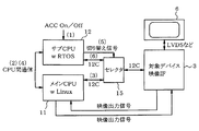
- a first selector 15 for switching the access right between the main CPU 11 and the sub CPU 11 for the video IF 3 is provided. 15 is controlled to be switched by a switching signal from the sub CPU 12.
- a communication method based on I2C is employed between the CPUs 11 and 12 and the video IF 3.
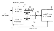
- a second selector 16 for switching the access right between the main CPU 11 and the sub CPU 11 is provided for the media device 4, and the second selector 16 is Again, switching control is performed by a switching signal from the sub CPU 12.
- communication by CMD SPI method
- the main CPU 11 when the system is terminated, that is, when the start switch (accessory switch) is turned off, the main CPU 11 reassigns control of the video IF 3 and the media device 4 to the sub CPU 12 and terminates itself. Process. Then, the sub CPU 12 performs a termination process of the video IF 3 and the media device 4 and then turns off the power of the main CPU 11 and shifts to a standby (sleep) state.
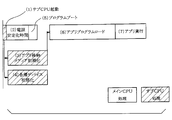
- the timing chart of FIG. 2 shows the processing contents of the main CPU 11 and the sub CPU 12 over time when the on-vehicle system 1 having the above configuration is activated (when the accessory switch is turned on).
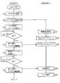
- 3 shows a processing procedure executed by the sub CPU 12 and the main CPU 11 at the time of activation (when the accessory switch is turned on).
- the described flowchart includes a plurality of sections (or referred to as steps), and each section is expressed as, for example, S1 or M1. Further, each section can be divided into a plurality of subsections, while a plurality of sections can be combined into one section. Each section can be referred to as a transfer section, transfer device, transfer module, or assigner as a device, module, or unique name. Sections are related not only to (i) sections of software combined with hardware units (eg, computers, CPUs), but also (ii) sections of hardware (eg, integrated circuits, wiring logic circuits). It can be realized with or without the function of the device. Furthermore, the hardware section can be included inside the microcomputer.
- the accessory switch when the accessory switch is turned on, first, on the sub CPU 12 side, the activation process of the sub CPU 12 is performed in S1. In this case, since the sub CPU 12 is in a standby state (sleep state) when the system is stopped (when the accessory switch is turned off), the sub CPU 12 can be activated in a very short time (process (1) in FIG. 2). ). When the sub CPU 12 is activated, the main CPU 11 is activated in accordance with an instruction from the sub CPU 12 in S2.
- the initialization process of the media device 4 for storing applications is executed in S3.
- the initialization process of the media device 4 (process (3) in FIG. 2) is to stabilize the power supply in the main CPU 11 (process (2) in FIG. 2) and program boot (process (FIG. 2) ( It is executed in parallel with 5)) and requires a certain time (for example, 500 ms).
- process (3) in FIG. 2 it is determined whether or not the initialization process of the media device 4 has been completed. If completed (Yes in S4), the initialization of the media device 4 to the main CPU 11 is performed in S5. A notification that the processing is completed is performed, and a process for transferring the access right of the media device 4 is performed.
- the access right transfer process will be described later with reference to FIGS. 6A and 6B.
- the video IF 3 is executed in S6 (processing (4) in FIG. 2). As shown in FIG. 2, the initialization process of the video IF 3 can be executed in parallel with the initialization process of the media device 4 (process (3) in FIG. 2). Cost.
- S7 it is determined whether or not the initialization process of the video IF3 is completed. If completed (Yes in S7), the initialization process of the video IF3 is performed on the main CPU 11 in S8. A notification of the completion is performed, and a process for transferring the access right of the video IF 3 is performed. The access right transfer process will be described later with reference to FIGS. 5A and 5B.
- the main CPU 11 after the program boot process of M2 is completed, when the access right of the media device 4 is transferred from the sub CPU 12 as described above (S5), the media device is transmitted in M3.
- the application program from 4 is loaded. For example, 1000 ms is required for loading the application program (process (6) in FIG. 2).
- the main CPU 11 performs a video setting process at M4, and further executes an application at M5 (the process (FIG. 2)). 7)).
- the initialization processing of the media device 4 and the video IF 3 that are peripheral devices is executed by the sub CPU 12 operated by the real-time OS at the time of activation. Therefore, the initialization process of the media device 4 and the video IF 3 can be performed in parallel with the startup process in the main CPU 11, that is, the process of the power supply stabilization time (2) and the program boot (5). The time required for the startup process of the entire system 1 can be shortened.
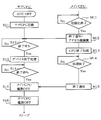
- FIG. 4 shows a processing procedure executed by the sub CPU 12 and the main CPU 11 when the system is terminated, that is, when the accessory switch is turned off. That is, when the accessory switch is turned off, first, the startup process of the sub CPU 12 in the standby state is performed in S11. When the activation process is performed, a notification wait state from the main CPU 11 is entered in S12.
- termination processing such as termination of the control program for each device is executed (M11).
- the termination notification is sent to the sub CPU 12 in M12, and the access right to each of the devices 3 and 4 is transferred.
- the process of transferring the access right from the main CPU 11 to the sub CPU 12 at the end will also be described with reference to FIGS. 5A, 5B, 6A, and 6B.
- the main CPU 11 continues its own termination process at M13.
- M14 it is determined whether or not the termination process is terminated.
- a termination notification is sent to the sub CPU 12 in M15.
- the processing when the accessory switch is turned off in the main CPU 11 is finished, and the power of the main CPU 11 is turned off by the sub CPU 12 (S15 described later).
- the sub CPU 12 when the end notification and the transfer of the access right are performed from the main CPU 11 (M12), the end waiting state ends (Yes in S12), and in S13, each of the devices 3 and 4 End processing (reset, power off, etc.) is executed.
- the main CPU 11 waits for an end notification.
- the main CPU 11 receives an end notification of M15 (Yes in S14)
- the main CPU 11 is powered off in S15, and then its own end processing is executed in S16. Thereafter, the sub CPU 12 is set in a standby state (sleep state).
- the control of the peripheral devices 3 and 4 is transferred from the main CPU 11 to the sub CPU 12, and the sub CPU 12 performs the termination processing of the peripheral devices 3 and 4.
- the end processing of the devices 3 and 4 and the sub CPU 12 can be efficiently performed, and the end processing can be performed in a short time.
- the sub CPU 12 can enter the standby state to monitor each of the peripheral devices 3 and 4, and the startup process at the next startup can be performed in a short time.
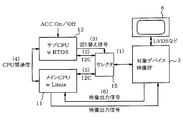
- FIG. 5A shows an operation procedure when the system is started
- FIG. 5B shows an operation procedure when the system is terminated.
- a communication method based on the I2C standard is adopted between the video IF 3 and the main CPU 11 and the sub CPU 11, and the first selector 15 provided between them is switched by a switching signal from the sub CPU 12. Controlled, switch access rights.
- the access right is set on the sub CPU 12 side by the first selector 15 (operation (1)), and the sub CPU 12 starts the initial operation of the video IF 3.
- the process is executed (operation (2)).
- the first selector 15 switches the access right to the main CPU 11 by the switching signal from the sub CPU 12 (operation (3)), and the sub CPU 12 accesses the main CPU 11 by inter-CPU communication.
- the fact that the right has been transferred is notified (operation (4)).
- the main CPU 11 sets a video format for the video IF 3 (operation (5)), and input / output of the video signal from the main CPU 11 is started (operation (6)).
- the following operation is executed. That is, when the sub CPU 12 detects that the accessory switch is turned off (operation (1)), the sub CPU 12 notifies the main CPU 11 that the accessory switch is turned off by the inter-CPU communication (operation (2)). Next, the main CPU 11 performs end processing of the device (video IF 3) (black image on the screen of the display device 6) (operation (3)), and notifies the sub CPU 12 of completion of the end processing through inter-CPU communication ( Operation (4)). Then, in response to the switching signal from the sub CPU 12, the first selector 15 switches the access right to the sub CPU 12 (operation (5)), and the sub CPU 12 executes the reset process of the video IF 3 (operation (6)).
- FIG. 6A and 6B show an operation procedure for switching (transferring) control between the main CPU 11 and the sub CPU 12 for the media device 4 among the devices.
- FIG. 6A shows an operation procedure at the time of system startup, and FIG. Shows the operation procedure at the end of the system.
- a communication method based on the CMD standard is adopted between the media device 4 and the main CPU 11 and the sub CPU 11, and the second selector 16 provided between them is based on a switching signal from the sub CPU 12. The switching is controlled and the access right is switched.
- the access right is set on the sub CPU 12 side by the second selector 16 (operation (1)).
- An initialization process is executed (operation (2)).
- the second selector 16 switches the access right to the main CPU 11 by the switching signal from the sub CPU 12 (operation (3)), and the sub CPU 12 communicates with the main CPU 11 by inter-CPU communication. Notify that the access right has been transferred (operation (4)).
- the main CPU 11 executes a read / write command for the media device 4 (operation (5)), and executes data transfer from the media device 4 to the main CPU 11 (operation (6)).
- the sub CPU 12 detects that the accessory switch is turned off (operation (1))
- the sub CPU 12 switches the accessory switch to the main CPU 11 through inter-CPU communication. Notify that it has been turned off (operation (2)).
- the main CPU 11 performs termination processing of the media device 4 (for example, output of a CMD0 signal) (operation (3)), and notifies the sub CPU 12 of completion of termination processing through inter-CPU communication (operation (4)).
- the second selector 16 switches the access right to the sub CPU 12 (operation (5)), and the sub CPU 12 executes power-off or standby processing of the media device 4 (operation ( 6)).
- the video IF 3 and the media device 4 as peripheral devices are controlled by the main CPU 11 operated by the Linux OS during normal operation, and at the time of system startup.
- the main CPU 11 operated by the Linux OS Is configured such that the sub CPU 12 operated by the real-time OS performs the initialization process.
- the control can be optimized by changing the CPUs 11 and 12 that control the device between the system startup and the normal operation.
- the present embodiment it is possible to achieve a high speed system startup process, and to obtain an excellent effect that it is possible to shorten the time required for the startup process to be completed.
- the time can be shortened to 2 seconds or less, which is also effective from the viewpoint of improving safety.
- selectors 15 and 16 for switching the access right between the main CPU 11 and the sub CPU 12 are provided for the peripheral devices 3 and 4, and the selectors 15 and 16 are switched by a switching signal from the sub CPU 12. Since the 16 switching control is performed, the transfer of control can be easily realized.
- the control of the peripheral devices 3 and 4 is transferred from the main CPU 11 to the sub CPU 12, and the sub CPU 12 performs the termination processing of the peripheral devices 3 and 4 and then shifts to the standby state. It was set as the structure to do. Thereby, the termination process at the time of system termination can also be efficiently performed. Moreover, even when the accessory switch is turned off, the sub CPU 12 can be in a standby state to monitor the peripheral devices 3 and 4, and at the time of activation, the peripheral devices 3 and 4 can be activated quickly.
- the present disclosure has been described with reference to the embodiments, it is understood that the present disclosure is not limited to the embodiments and structures.
- the present disclosure includes various modifications and modifications within the equivalent range.
- various combinations and forms, as well as other combinations and forms including only one element, more or less, are within the scope and spirit of the present disclosure.
- the case where Linux is adopted as a general-purpose OS on which the main CPU operates has been exemplified.
- the present invention is not limited to this. it can.
- the communication system in each unit, the data transmission standard, etc. are merely examples, and various technologies can be employed.
- the video IF 3 and the media device 4 are exemplified as the peripheral devices.
- the present disclosure can be applied to all devices mounted on the vehicle.
- various changes can be made to the hardware configuration of the entire in-vehicle system, the software or hardware configuration of the control device, and the like.
Landscapes
- Engineering & Computer Science (AREA)
- Theoretical Computer Science (AREA)
- Software Systems (AREA)
- Physics & Mathematics (AREA)
- General Physics & Mathematics (AREA)
- General Engineering & Computer Science (AREA)
- Mechanical Engineering (AREA)
- Computer Security & Cryptography (AREA)
- Computer Hardware Design (AREA)
- Automation & Control Theory (AREA)
- Multimedia (AREA)
- Signal Processing (AREA)
- Chemical & Material Sciences (AREA)
- Combustion & Propulsion (AREA)
- Transportation (AREA)
- Stored Programmes (AREA)
Abstract
Description
尚、上記実施形態では、メインCPUが動作する汎用OSとしてLinuxを採用した場合を例示したが、これに限定されるものではなく、例えばWindows(登録商標)等の各種のOSを採用することもできる。各部における通信方式や、データ伝送の規格等についても、一例を示したに過ぎず、各種の技術を採用することができる。また、上記実施形態では、周辺デバイスとして、映像IF3及びメディアデバイス4を例示したが、本開示は、車両に搭載されているデバイス全般を対象として適用することができる。その他、車載システム全体のハードウエア構成や、制御装置のソフトウエアあるいはハードウエア構成等についても種々の変更が可能である。
Claims (5)
- 車両に搭載され、汎用OSにより動作するメインCPU(11)と、そのメインCPU(11)により制御される周辺デバイス(3,4)とを備える車載システム(1)であって、
リアルタイムOSにより動作するサブCPU(12)を設けると共に、
起動時において、前記サブCPUにより、前記周辺デバイスの初期化処理を行い、その後、該サブCPUから前記メインCPUに前記周辺デバイスの制御を譲渡するように構成されている
車載システム。 - 前記周辺デバイスには、表示装置(6)の画面表示を行う映像インターフェース(3)が含まれている
請求項1記載の車載システム。 - 前記周辺デバイスには、前記メインCPUのアプリケーションプログラムを格納するメディアデバイス(4)が含まれている
請求項1又は2記載の車載システム。 - 前記周辺デバイス(3,4)に対し、前記メインCPUとサブCPUとの間でアクセス権を切替えるためのセレクタ(15,16)が設けられ、前記サブCPUからの切替え信号により該セレクタを切替え制御することにより、制御の譲渡が行われる
請求項1から3のいずれか一項に記載の車載システム。 - 終了時においては、前記メインCPUから前記サブCPUに前記周辺デバイスの制御を譲渡し、該サブCPUは、前記周辺デバイスの終了処理を行った後、スタンバイ状態に移行する
請求項1から4のいずれか一項に記載の車載システム。
Priority Applications (3)
| Application Number | Priority Date | Filing Date | Title |
|---|---|---|---|
| US15/557,902 US10569726B2 (en) | 2015-03-25 | 2016-03-11 | In-vehicle system |
| DE112016001377.9T DE112016001377B4 (de) | 2015-03-25 | 2016-03-11 | Fahrzeugbordsystem |
| KR1020177027026A KR101979138B1 (ko) | 2015-03-25 | 2016-03-11 | 차량 탑재 시스템 |
Applications Claiming Priority (2)
| Application Number | Priority Date | Filing Date | Title |
|---|---|---|---|
| JP2015062519A JP2016179801A (ja) | 2015-03-25 | 2015-03-25 | 車載システム |
| JP2015-062519 | 2015-03-25 |
Publications (1)
| Publication Number | Publication Date |
|---|---|
| WO2016152064A1 true WO2016152064A1 (ja) | 2016-09-29 |
Family
ID=56977238
Family Applications (1)
| Application Number | Title | Priority Date | Filing Date |
|---|---|---|---|
| PCT/JP2016/001377 Ceased WO2016152064A1 (ja) | 2015-03-25 | 2016-03-11 | 車載システム |
Country Status (6)
| Country | Link |
|---|---|
| US (1) | US10569726B2 (ja) |
| JP (1) | JP2016179801A (ja) |
| KR (1) | KR101979138B1 (ja) |
| DE (1) | DE112016001377B4 (ja) |
| TW (1) | TWI613104B (ja) |
| WO (1) | WO2016152064A1 (ja) |
Cited By (1)
| Publication number | Priority date | Publication date | Assignee | Title |
|---|---|---|---|---|
| EP4353538A1 (en) * | 2022-10-10 | 2024-04-17 | Aptiv Technologies Limited | A control system for a vehicle and method of implementing same |
Families Citing this family (8)
| Publication number | Priority date | Publication date | Assignee | Title |
|---|---|---|---|---|
| JP2019053452A (ja) * | 2017-09-14 | 2019-04-04 | 株式会社明電舎 | 情報処理装置 |
| CN110069336A (zh) * | 2018-01-22 | 2019-07-30 | 合肥杰发科技有限公司 | 内存资源分配方法、分配装置、芯片和存储装置 |
| JP6996429B2 (ja) * | 2018-06-08 | 2022-01-17 | 住友電装株式会社 | 車載通信装置及び車載装置起動方法 |
| DE102019203377B3 (de) | 2019-03-13 | 2020-08-13 | Continental Automotive Gmbh | Fahrzeugsystem, Fahrzeug und Verfahren zum Betreiben eines solchen Fahrzeugsystems |
| JP2020149317A (ja) * | 2019-03-13 | 2020-09-17 | 株式会社デンソー | 車両用装置 |
| WO2021016931A1 (zh) * | 2019-07-31 | 2021-02-04 | 华为技术有限公司 | 一种集成芯片以及处理传感器数据的方法 |
| JP7503018B2 (ja) * | 2021-03-30 | 2024-06-19 | 本田技研工業株式会社 | 車載電子システム、車両、制御方法、及びプログラム |
| CN117622001B (zh) * | 2023-11-30 | 2025-03-25 | 艾贝科技(深圳)有限公司 | 一种电子后视镜系统 |
Citations (8)
| Publication number | Priority date | Publication date | Assignee | Title |
|---|---|---|---|---|
| JP2003114804A (ja) * | 2001-10-03 | 2003-04-18 | Okuma Corp | リアルタイムos制御装置 |
| US20080077786A1 (en) * | 2006-09-27 | 2008-03-27 | Pierce James R | Rapid-boot computing device with dual operating systems |
| JP2009078752A (ja) * | 2007-09-27 | 2009-04-16 | Mitsubishi Motors Corp | 車両の電源制御装置 |
| JP2009258986A (ja) * | 2008-04-16 | 2009-11-05 | Fujitsu Ten Ltd | コンテンツ再生装置、及び電子機器 |
| JP2011215796A (ja) * | 2010-03-31 | 2011-10-27 | Ricoh Co Ltd | 制御装置及び制御方法 |
| JP2012074863A (ja) * | 2010-09-28 | 2012-04-12 | Mitsubishi Electric Corp | 映像再生装置及び起動方法 |
| JP2013097728A (ja) * | 2011-11-04 | 2013-05-20 | Nikon Corp | 電子機器およびプログラム |
| JP2014197370A (ja) * | 2013-03-08 | 2014-10-16 | 株式会社デンソー | データ処理装置 |
Family Cites Families (9)
| Publication number | Priority date | Publication date | Assignee | Title |
|---|---|---|---|---|
| JP3049651B2 (ja) * | 1997-10-31 | 2000-06-05 | 株式会社ウェルビーン | マルチcpu装置 |
| US8781442B1 (en) * | 2006-09-08 | 2014-07-15 | Hti Ip, Llc | Personal assistance safety systems and methods |
| JP2008137559A (ja) * | 2006-12-04 | 2008-06-19 | Fujitsu Ten Ltd | 車載用電子システム、車載電子装置及び携帯電子装置の電源制御方法 |
| JP2009128313A (ja) | 2007-11-27 | 2009-06-11 | Hitachi Ltd | カーナビゲーション装置、制御方法、プログラムおよび制御装置 |
| JP2010079566A (ja) * | 2008-09-25 | 2010-04-08 | Alpine Electronics Inc | 情報処理装置およびアプリケーション起動方法 |
| JP5750862B2 (ja) | 2010-01-15 | 2015-07-22 | カシオ計算機株式会社 | 測位装置、測位方法およびプログラム |
| JP2013152509A (ja) | 2012-01-24 | 2013-08-08 | Sharp Corp | 画像処理装置 |
| JP2014048817A (ja) | 2012-08-30 | 2014-03-17 | Sony Corp | 情報処理装置、情報処理方法及びプログラム |
| CA2849383C (en) * | 2013-08-20 | 2016-06-07 | Yasunori Kimura | Construction machine controller |
-
2015
- 2015-03-25 JP JP2015062519A patent/JP2016179801A/ja active Pending
-
2016
- 2016-03-11 DE DE112016001377.9T patent/DE112016001377B4/de active Active
- 2016-03-11 KR KR1020177027026A patent/KR101979138B1/ko not_active Expired - Fee Related
- 2016-03-11 WO PCT/JP2016/001377 patent/WO2016152064A1/ja not_active Ceased
- 2016-03-11 US US15/557,902 patent/US10569726B2/en active Active
- 2016-03-21 TW TW105108663A patent/TWI613104B/zh not_active IP Right Cessation
Patent Citations (8)
| Publication number | Priority date | Publication date | Assignee | Title |
|---|---|---|---|---|
| JP2003114804A (ja) * | 2001-10-03 | 2003-04-18 | Okuma Corp | リアルタイムos制御装置 |
| US20080077786A1 (en) * | 2006-09-27 | 2008-03-27 | Pierce James R | Rapid-boot computing device with dual operating systems |
| JP2009078752A (ja) * | 2007-09-27 | 2009-04-16 | Mitsubishi Motors Corp | 車両の電源制御装置 |
| JP2009258986A (ja) * | 2008-04-16 | 2009-11-05 | Fujitsu Ten Ltd | コンテンツ再生装置、及び電子機器 |
| JP2011215796A (ja) * | 2010-03-31 | 2011-10-27 | Ricoh Co Ltd | 制御装置及び制御方法 |
| JP2012074863A (ja) * | 2010-09-28 | 2012-04-12 | Mitsubishi Electric Corp | 映像再生装置及び起動方法 |
| JP2013097728A (ja) * | 2011-11-04 | 2013-05-20 | Nikon Corp | 電子機器およびプログラム |
| JP2014197370A (ja) * | 2013-03-08 | 2014-10-16 | 株式会社デンソー | データ処理装置 |
Cited By (1)
| Publication number | Priority date | Publication date | Assignee | Title |
|---|---|---|---|---|
| EP4353538A1 (en) * | 2022-10-10 | 2024-04-17 | Aptiv Technologies Limited | A control system for a vehicle and method of implementing same |
Also Published As
| Publication number | Publication date |
|---|---|
| US20180056898A1 (en) | 2018-03-01 |
| JP2016179801A (ja) | 2016-10-13 |
| KR20170120671A (ko) | 2017-10-31 |
| DE112016001377T5 (de) | 2017-12-14 |
| US10569726B2 (en) | 2020-02-25 |
| DE112016001377B4 (de) | 2023-01-05 |
| TW201706157A (zh) | 2017-02-16 |
| TWI613104B (zh) | 2018-02-01 |
| KR101979138B1 (ko) | 2019-05-15 |
Similar Documents
| Publication | Publication Date | Title |
|---|---|---|
| WO2016152064A1 (ja) | 車載システム | |
| CN111976482B (zh) | 一种车载仪表屏和中控娱乐屏的双屏交互系统及方法 | |
| US8892935B2 (en) | Dynamic bus clock rate adjusting method and device | |
| CN112199222B (zh) | 一种视频显示方法、装置、电子设备及存储介质 | |
| KR20200042798A (ko) | 이종 운영체제의 실행을 제어하기 위한 방법, 이를 위한 전자 장치 및 저장 매체 | |
| CN105786424A (zh) | 嵌入式系统的单屏幕快速分屏显示解决的方法 | |
| WO2016072071A1 (ja) | 車両用機器 | |
| CN110641478A (zh) | 汽车域控制器显示方法、装置、汽车以及可读存储介质 | |
| KR100754534B1 (ko) | 무선 통신 디바이스 및 그 시스템 기동 방법 | |
| JP6272579B2 (ja) | アプリケーション実行装置およびアプリケーション実行方法 | |
| US10162647B2 (en) | Information apparatus | |
| JP6272580B2 (ja) | アプリケーション実行装置およびアプリケーション実行方法 | |
| JP6237543B2 (ja) | 車載装置 | |
| US11225143B2 (en) | System having an infotainment system | |
| CN107888876B (zh) | 车载信息娱乐系统及其早期影像显示的方法 | |
| CN113747043B (zh) | 图像处理器启动方法、电子设备和存储介质 | |
| CN115904295B (zh) | 一种多屏显示控制方法、装置、介质、系统、芯片及面板 | |
| WO2017037817A1 (ja) | アプリケーション実行装置およびアプリケーション実行方法 | |
| JP2009223805A (ja) | 情報処理装置およびデバイスコントローラの駆動制御方法 | |
| WO2016013155A1 (ja) | 車両用装置及び状態遷移プログラム製品 | |
| WO2020184074A1 (ja) | 車両用装置 | |
| JP7599580B2 (ja) | 電子機器および高速通信方法 | |
| JP7715674B2 (ja) | 電子制御装置、リプロ実施方法及びリプロ実施プログラム | |
| JP6528901B2 (ja) | 通信機器、通信機器の制御方法、及び記録媒体 | |
| CN119078693A (zh) | 域控制器及其启动控制方法、装置、电子设备和存储介质 |
Legal Events
| Date | Code | Title | Description |
|---|---|---|---|
| 121 | Ep: the epo has been informed by wipo that ep was designated in this application |
Ref document number: 16767974 Country of ref document: EP Kind code of ref document: A1 |
|
| WWE | Wipo information: entry into national phase |
Ref document number: 15557902 Country of ref document: US |
|
| ENP | Entry into the national phase |
Ref document number: 20177027026 Country of ref document: KR Kind code of ref document: A |
|
| WWE | Wipo information: entry into national phase |
Ref document number: 112016001377 Country of ref document: DE |
|
| 122 | Ep: pct application non-entry in european phase |
Ref document number: 16767974 Country of ref document: EP Kind code of ref document: A1 |