WO2016152000A1 - Appareil d'assistance de confirmation de sécurité, procédé d'assistance de confirmation de sécurité - Google Patents
Appareil d'assistance de confirmation de sécurité, procédé d'assistance de confirmation de sécurité Download PDFInfo
- Publication number
- WO2016152000A1 WO2016152000A1 PCT/JP2016/000740 JP2016000740W WO2016152000A1 WO 2016152000 A1 WO2016152000 A1 WO 2016152000A1 JP 2016000740 W JP2016000740 W JP 2016000740W WO 2016152000 A1 WO2016152000 A1 WO 2016152000A1
- Authority
- WO
- WIPO (PCT)
- Prior art keywords
- obstacle
- vehicle
- camera
- display
- safety confirmation
- Prior art date
Links
- 238000012790 confirmation Methods 0.000 title claims abstract description 45
- 238000000034 method Methods 0.000 title claims description 19
- 238000003384 imaging method Methods 0.000 claims abstract description 14
- 238000001514 detection method Methods 0.000 claims description 15
- 230000004048 modification Effects 0.000 description 29
- 238000012986 modification Methods 0.000 description 29
- 230000008569 process Effects 0.000 description 10
- 230000006870 function Effects 0.000 description 3
- 238000005516 engineering process Methods 0.000 description 2
- 238000013459 approach Methods 0.000 description 1
- 230000008859 change Effects 0.000 description 1
- 238000004590 computer program Methods 0.000 description 1
- 230000012447 hatching Effects 0.000 description 1
- 239000004973 liquid crystal related substance Substances 0.000 description 1
- 239000000463 material Substances 0.000 description 1
- 230000015654 memory Effects 0.000 description 1
- 238000012545 processing Methods 0.000 description 1
Images


Classifications
-
- G—PHYSICS
- G08—SIGNALLING
- G08G—TRAFFIC CONTROL SYSTEMS
- G08G1/00—Traffic control systems for road vehicles
- G08G1/16—Anti-collision systems
- G08G1/165—Anti-collision systems for passive traffic, e.g. including static obstacles, trees
-
- B—PERFORMING OPERATIONS; TRANSPORTING
- B60—VEHICLES IN GENERAL
- B60R—VEHICLES, VEHICLE FITTINGS, OR VEHICLE PARTS, NOT OTHERWISE PROVIDED FOR
- B60R1/00—Optical viewing arrangements; Real-time viewing arrangements for drivers or passengers using optical image capturing systems, e.g. cameras or video systems specially adapted for use in or on vehicles
- B60R1/20—Real-time viewing arrangements for drivers or passengers using optical image capturing systems, e.g. cameras or video systems specially adapted for use in or on vehicles
- B60R1/22—Real-time viewing arrangements for drivers or passengers using optical image capturing systems, e.g. cameras or video systems specially adapted for use in or on vehicles for viewing an area outside the vehicle, e.g. the exterior of the vehicle
- B60R1/23—Real-time viewing arrangements for drivers or passengers using optical image capturing systems, e.g. cameras or video systems specially adapted for use in or on vehicles for viewing an area outside the vehicle, e.g. the exterior of the vehicle with a predetermined field of view
- B60R1/26—Real-time viewing arrangements for drivers or passengers using optical image capturing systems, e.g. cameras or video systems specially adapted for use in or on vehicles for viewing an area outside the vehicle, e.g. the exterior of the vehicle with a predetermined field of view to the rear of the vehicle
-
- B—PERFORMING OPERATIONS; TRANSPORTING
- B60—VEHICLES IN GENERAL
- B60R—VEHICLES, VEHICLE FITTINGS, OR VEHICLE PARTS, NOT OTHERWISE PROVIDED FOR
- B60R21/00—Arrangements or fittings on vehicles for protecting or preventing injuries to occupants or pedestrians in case of accidents or other traffic risks
-
- G—PHYSICS
- G08—SIGNALLING
- G08G—TRAFFIC CONTROL SYSTEMS
- G08G1/00—Traffic control systems for road vehicles
- G08G1/16—Anti-collision systems
Definitions
- the present disclosure relates to a safety confirmation support device (apparatus) and a safety confirmation support method (method) that support safety confirmation of a driver of a vehicle.
- Patent Literature In order to support vehicle driver safety confirmation, a technology has been developed that displays an image of the surroundings of a vehicle on a vehicle-mounted monitor. The driver can grasp surrounding obstacles and the like from the displayed image. In addition to displaying a photographed image, a technique has been proposed that guides driving by predicting the traveling trajectory of the vehicle in the image and displaying the predicted traveling trajectory together (Patent Literature). 1).
- the predicted travel trajectory is simply superimposed on the captured image, so the positional relationship between the obstacle in the image and the predicted travel trajectory (whether it collides with the obstacle or behind the obstacle) It may be difficult for the driver to grasp whether or not the vehicle will collide with the vehicle, and eventually it must be visually confirmed.
- This disclosure is intended to provide a display technique that allows a driver to easily grasp whether or not an obstacle in an image of a display device collides with a predicted traveling trajectory of a vehicle.
- a safety confirmation support device and a safety confirmation support method capture a predetermined imaging region set around a vehicle with a camera, predict a traveling trajectory of the vehicle in the imaging region, and capture the camera An obstacle is detected from the image. Also, obstacle information related to the obstacle is acquired at a position different from the shooting position of the camera, and it is determined whether or not the vehicle collides with the obstacle based on the obstacle information. Then, a display installed at a position visible from the driver's seat of the vehicle is controlled, and a traveling track is added to the captured image of the camera for display, and a determination result as to whether the vehicle collides with an obstacle is displayed. This is reflected in the display mode of the display.
- obstacle information is separately acquired at a position different from the shooting position of the camera, and the display mode of the display device is made different depending on the presence or absence of a collision between the vehicle and the obstacle determined based on the obstacle information.
- the driver can intuitively grasp whether or not the vehicle collides with the obstacle from the display on the display. As a result, it is not necessary to visually check the obstacle, and the driver can easily check the safety.
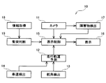
- FIG. 1 shows the configuration of a safety confirmation support apparatus 10 of this embodiment.
- the safety confirmation support apparatus 10 of the present embodiment is configured to function as an electronic control unit or an electronic control circuit. It is mounted on a vehicle (also referred to as a host vehicle or a target vehicle) and supports driver's safety confirmation.
- the safety confirmation support apparatus 10 includes a camera 11, a traveling trajectory prediction unit 12, a rudder angle detector 13, a vehicle speed detector 14, a display control unit 15, a display 16, and an obstacle detection.
- a component such as a unit 17, an information acquisition unit 18, and a collision determination unit 19 are provided. Note that these components 12 to 19 are conceptually classified by focusing on the functions of the safety confirmation support apparatus 10, and each of them does not necessarily exist physically independently.
- Each of these can be configured by various devices, electronic components, integrated circuits, computers including CPUs and memories, computer programs, or combinations thereof.
- the camera 11 is attached to the vehicle and images a predetermined imaging area set around the vehicle.
- the camera 11 of this embodiment captures a moving image.
- the traveling trajectory prediction unit 12 is connected to a steering angle detector 13 that detects a steering angle of the vehicle (an angle at which the driver turns the steering wheel) and a vehicle speed detector 14 that detects a traveling speed (vehicle speed) of the vehicle. Based on the steering angle and the vehicle speed, the traveling track of the vehicle is predicted.
- the display control unit 15 controls the display 16 that can display an image to display a photographed image of the camera 11, and the traveling trajectory predicted by the traveling trajectory prediction unit 12 passes through the photographing region of the camera 11. In this case, the traveling track is added to the captured image and displayed.
- the obstacle detection unit 17 analyzes an image captured by the camera 11 and detects an obstacle in the captured image.
- the information acquisition unit 18 acquires information on the obstacle (obstacle information) at a position different from the shooting position of the camera 11.
- the information acquisition unit 18 is a so-called radar, which emits radio waves (millimeter waves) toward a predetermined detection area set around the vehicle and receives the reflected waves to check whether there is an obstacle. Acquire the position etc. as obstacle information. Note that information is used not only as countable nouns but also as countable nouns, and a plurality of pieces of information are equivalent to a plurality of information items.
- the collision determination unit 19 determines whether or not the vehicle collides with the obstacle based on the obstacle information acquired by the information acquisition unit 18.
- the display control unit 15 of this embodiment is connected to the obstacle detection unit 17 and the collision determination unit 19 and switches the display mode of the display 16 according to the determination result of the collision determination unit 19.
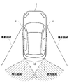
- FIG. 2 shows a shooting area of the camera 11 and a detection area of the information acquisition unit 18 (radar) set around the vehicle 1 of the present embodiment.
- a pair of left and right cameras 11 are provided on the side surface of the vehicle 1, and an area from the camera 11 toward the rear of the vehicle 1 is set as a shooting area, and includes a rear side portion of the vehicle 1.
- the vehicle 1 of the present embodiment does not have a side mirror (door mirror), but instead has a side mirror in which the area reflected on the side mirror is set as a shooting area and is shot with the camera 11. It has become.
- a pair of left and right radars as information acquisition devices 18 are provided at the rear end of the vehicle 1, and detection areas are set on the left and right rear sides of the vehicle 1, partially overlapping with the shooting area of the camera 11. Yes.
- the information acquisition unit 18 is not limited to a radar as long as it can detect the presence or absence or position of an obstacle, and may be a sonar that detects sound waves or a laser sensor that detects light.
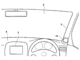
- FIG. 3 shows the indicator 16 provided in the vehicle 1 of the present embodiment.
- the display 16 is installed in a pair of left and right windows (so-called A pillars) 3 on the left and right sides of the windshield 2 (the left display 16 is not shown).
- a display screen composed of a liquid crystal display or the like is directed to the driver (driver's seat).
- the left and right of the image captured by the camera 11 are reversed and displayed on the display 16. The driver can check the rear side from the side surface of the vehicle 1 by looking at the display 16 as with the side mirror.
- the position where the display 16 is installed is not limited to the A pillar as long as it is visible from the driver's seat, and may be embedded in the left and right ends of the dashboard 4 or in the door panel, for example. Further, a photographed image of the camera 11 may be displayed using a display 5 of a car navigation system installed at substantially the center of the dashboard 4 as a display.
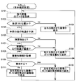
- FIG. 4 shows a flowchart of a safety confirmation support process (also referred to as a safety confirmation support method) executed by the safety confirmation support apparatus 10 (or electronic control unit) of the present embodiment.
- the described flowchart includes a plurality of sections (or referred to as steps), and each section is expressed as, for example, S110. Further, each section can be divided into a plurality of subsections, while a plurality of sections can be combined into one section.
- Each section can be referred to as a device, module, or unique name, for example, a detection section can be referred to as a detection device, detection module, detector.
- the section includes (i) not only a section of software combined with a hardware unit (eg, a computer) but also (ii) a section of hardware (eg, an integrated circuit, a wiring logic circuit) and related devices. It can be realized with or without the function.
- the hardware section can be included inside the microcomputer.
- the shift lever of the vehicle 1 is in the reverse (R) position (S102).
- the traveling track of the vehicle 1 passes through the imaging region of the camera 11, the traveling track can be added to the captured image and displayed on the display 16.
- the shift lever is not in the reverse (R) position (S102: no)
- the traveling trajectory is not added to the rear image of the vehicle 1, and the captured image of the camera 11 is reversed left and right and displayed on the display 16 as it is. It is displayed (S103).
- the driver can check the rear of the vehicle 1 with the image displayed on the display device 16 in the same manner as the side mirror.
- the reverse image is displayed on the display device 16 in this way, the process returns to the top of the safety confirmation support process, and the image data captured by the camera 11 is acquired again (S101).
- the traveling path of the vehicle 1 is predicted based on the steering angle and the vehicle speed (S104).
- the traveling track depends not only on the rudder angle but also on the vehicle speed. If the rudder angle is the same, the turning radius increases as the vehicle speed increases.
- a traveling track of a predetermined distance (for example, 1.5 vehicle length) is predicted from the rear wheel of the vehicle 1 toward the rear.
- the travel trajectory may be predicted for at least the imaging region of the camera 11.
- the image data captured by the camera 11 is analyzed to determine whether there is an obstacle in the captured image (S105).
- a person or an object included in a range where there is a possibility of colliding with the vehicle 1 when viewed from the position of the camera 11 is detected as an obstacle.
- a plurality of templates of silhouettes of various obstacles are prepared in advance, and a silhouette that matches one of the templates exists in a predetermined range (for example, a range from the vehicle 1 to 0.5 vehicle length) in the photographed image.
- An obstacle may be detected based on whether or not to do so, or an obstacle in a predetermined range may be detected by comparison (parallax) with an image taken from a position different from the camera 11.
- an obstacle may be detected (specified) from the captured image based on the obstacle information acquired by the information acquisition unit 18.
- the captured image of the camera 11 is reversed left and right and displayed on the display 16 and a guide line representing the traveling trajectory predicted in S104 is reversed. (S106).
- the driver can not only confirm the rear of the vehicle 1 on the display of the display 16 but also can register the destination of the vehicle 1 moving backward. Note that the color of the guide line displayed in S106 is set to yellow.
- the information acquisition unit 18 uses the obstacle information such as the presence or absence of the obstacle and the position thereof. (S108), and based on the obstacle information, it is determined whether or not the vehicle 1 collides with the obstacle (S109). Since the information acquisition unit 18 acquires the obstacle information at a position different from the shooting position of the camera 11, even if the information acquisition unit 18 appears to collide with the obstacle from the shooting position of the camera 11, the information acquisition unit 18 has an obstacle. From the information, it is not always determined that the vehicle collides with the obstacle, and it may be determined that the vehicle does not collide.
- the captured image of the camera 11 is reversed left and right and displayed on the display 16 and the obstacle in the image is displayed.
- the guide lines are displayed in a collision mode in which the guide lines overlap with each other (S110). Note that the color of the guide line displayed in S110 is set to red.
- the captured image of the camera 11 is reversed left and right and displayed on the display 16 and superimposed on the obstacle in the guide line.
- the guide line is displayed in a collision avoidance mode in which the portion (superimposed portion) is not displayed (S111).
- the color of the guide line displayed in S111 is set to yellow. In this way, when a reverse line is displayed with a guide line added in a display mode according to the determination result of whether or not it collides with an obstacle, the process returns to the top of the safety confirmation support process and the above-described series of processes is repeated.
- C. Guide line display example As described above, in this embodiment, it is possible to add the traveling trajectory of the vehicle 1 to the captured image of the camera 11 and display it on the display device 16, and to collide with an obstacle based on the obstacle information of the information acquisition device 18.
- a guide line (traveling trajectory) is displayed in a collision mode or a collision avoidance mode according to the determination result of whether or not to do so.
- a display example of a guide line will be described.
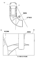
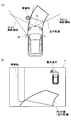
- FIG. 5 shows an example in which guide lines are displayed in a collision mode.
- the vehicle 1 moves backward while turning the handle to the right, and the traveling track passes through the imaging area of the camera 11 on the right side.
- there is an obstacle on the right rear side of the vehicle 1 and this obstacle is detected in the captured image of the camera 11 and the traveling trajectory is superposed (when viewed from the position of the camera 11, the traveling trajectory is an obstacle). (It seems to collide with).
- the obstacle behind the obstacle is a blind spot as seen from the position of the camera 11, the obstacle information at the blind spot can be acquired by the information acquisition unit 18 (radar) at the right rear end of the vehicle 1.
- radar information acquisition unit 18
- an obstacle is detected in the detection area of the information acquisition unit 18, and it is determined that the vehicle 1 collides with the obstacle.
- the display mode of the guide line (traveling trajectory) is set to the collision mode, and as shown in FIG. 5B, the display unit 16 overlaps the obstacles in the captured image (front side).
- a guide line is displayed. By doing so, it is possible to impress the driver who has seen the display device 16 that the traveling track of the vehicle 1 collides with an obstacle (cannot wrap around behind).
- the guide line is displayed in red (yellow when there is no collision), or a mark indicating a collision (collision mark) is added to the collision location. Can be emphasized.
- a distance guide line indicating a distance from the vehicle 1 is attached to the guide line of the present embodiment every predetermined distance (for example, 1 m).
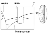
- FIG. 6 shows an example in which the guide line is displayed in a collision avoidance mode.
- the traveling track of the vehicle 1 that moves backward while turning the steering wheel to the right passes through the imaging region of the right camera 11, and the vehicle 1 Obstacles on the right rear of the camera 11 are detected in the captured image of the camera 11, and the traveling track is superimposed on the obstacle (when viewed from the position of the camera 11, the traveling track appears to collide with the obstacle).
- the information acquiring unit 18 radar
- the display mode of the guide line (traveling track) is set to the collision avoidance mode, and as shown in FIG. 6B, the display unit 16 erases the overlapping portion with the obstacle in the traveling track. (Hidden), the guide line of the non-overlapping part is displayed. In this way, by erasing the portion of the guide line that is hidden behind the obstacle and not visible, the traveling track of the vehicle 1 turns around behind the obstacle to the driver who has seen the display 16 and the obstacle. You can impress that it doesn't collide with.
- an obstacle shadow is added around the overlapping portion of the guide line and the obstacle as shown in an enlarged view in FIG.
- a light and dark gradation is applied so that the shadow becomes thinner toward the outside from the outline of the obstacle on the near side of the guide line.
- the safety confirmation support device 10 of the present embodiment when the traveling path of the vehicle 1 is added to the captured image of the camera 11 and displayed on the display 16, behind the obstacle detected in the captured image.
- Information on (dead angle) is acquired by an information acquisition unit 18 (radar) at a position different from that of the camera 11.
- the judgment result of the presence or absence of the collision between the vehicle 1 and the obstacle based on the obstacle information is reflected in the display mode of the display 16 and, in the case of a collision, the guide line is displayed in the collision mode (overlap with the obstacle).
- the guide line is displayed in a collision avoidance mode (erasing the overlapping portion with the obstacle).
- the collision avoidance mode of the guide line is not limited to this, and can be distinguished from the collision mode, as long as it is a display mode that impresses that the traveling track does not collide with the obstacle (it can go around behind the obstacle). Good.
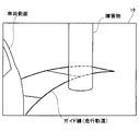
- FIG. 8 shows an example in which the guide line is displayed in a collision avoidance manner on the display 16 of the first modified example, and the illustrated example is the same situation as (a) of FIG.
- the guide line of the portion that does not overlap the obstacle (the portion that is not hidden by the obstacle) in the traveling track is displayed as a solid line on the display 16, whereas the overlapping portion with the obstacle ( The guide line of the part hidden behind the obstacle is displayed as a broken line (hidden line).
- the driving line of the vehicle 1 is obstructed by the driver who viewed the display 16 by changing the drawing mode of the guide line between the portion that is not hidden behind the obstacle and the portion that is not visible behind the obstacle. It can be impressed that it does not collide with obstacles by going behind the object.
- the drawing mode (drawing line) of the overlapping portion is not limited to the broken line, and may be a mode that can be distinguished from the non-overlapping portion.
- the display mode of the guide line is changed according to the determination result of the presence or absence of the collision between the vehicle 1 and the obstacle based on the obstacle information of the information acquisition unit 18.
- a display based on the obstacle information of the information acquisition unit 18 is added to the display unit 16 so that the driver can grasp whether the vehicle 1 collides with the obstacle. Good.
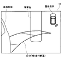
- FIG. 9 shows an example in which a guide line is displayed on the display 16 of the second modification.
- the traveling track of the vehicle 1 that moves backward while turning the handle to the right passes through the imaging region of the right camera 11, and the obstacle on the right rear of the vehicle 1 is the camera 11.
- the traveling trajectory is superimposed on the obstacle (when viewed from the position of the camera 11, the traveling trajectory appears to collide with the obstacle).
- an obstacle is detected in the detection area of the information acquisition unit 18 (radar) at the right rear end of the vehicle 1, and obstacle information such as the position and size of the obstacle is acquired.
- the traveling track and the obstacle are in a positional relationship that does not collide.
- a collision warning range that may collide with the obstacle is calculated if the traveling track is within the range.
- the left and right sides of the image captured by the camera 11 are reversed, and a guide line (traveling trajectory) is displayed on the inverted image, and the collision warning range is displayed. Is displayed.
- the driver who has seen the display unit 16 will collide with an obstacle if the guide line is in the collision warning range, and will not collide with the obstacle unless the guide line is in the collision warning range. Can show.
- FIG. 10 shows an example in which guide lines are displayed on the display 16 of the third modification.
- the illustrated example is a situation similar to (a) of FIG. 5, and is a case where it is determined that the vehicle 1 collides with an obstacle based on the obstacle information of the information acquisition unit 18.
- the display 16 displays a guide line (running trajectory) superimposed on a reversed image obtained by inverting the left and right of the image captured by the camera 11, and in addition, a warning display (characters and figures) for warning a collision is added. Is done.
- a graphic indicating the position of the collision is imitated as a warning display, imitating the vehicle 1.
- a warning display is not added, and only a guide line is displayed on the reverse image.
- the warning display of the third modification can also be applied to the above-described embodiment, the first modification, and the second modification, and the warning display when it is determined that the vehicle 1 collides with an obstacle. By adding, the collision can be further emphasized.
- FIG. 11 shows an example in which obstacle information is acquired by the safety confirmation support device 10 of the fourth modified example.
- FIG. 11A in the fourth modification example, from the rear end of the vehicle 1 separately from the camera 11 that captures the rear from the side surface of the vehicle 1 (referred to as “side camera” in the fourth modification example).
- a back camera 21 that captures the rear is provided as an information acquisition unit, and a shooting area (side shooting area) of the side camera 11 and a shooting area (back shooting area) of the back camera 21 partially overlap.
- the obstacle is included in both the side photographing region and the back photographing region, and the obstacle is determined by comparing (parallax) the photographed image of the side camera 11 and the photographed image of the back camera 21.
- Obstacle information such as the position and size of the can be acquired. Further, information behind an obstacle that becomes a blind spot when viewed from the position of the side camera 11 can be acquired from the position of the back camera 21. Therefore, even if the vehicle 1 appears to collide with an obstacle in the captured image of the side camera 11, as shown in FIG. 11B, the traveling trajectory is behind the obstacle in the captured image of the back camera 21. If it appears to pass, it can be determined that the vehicle 1 does not collide with an obstacle.
- a sonar that detects the approach of the obstacle may be used in combination. For example, if an obstacle is not detected by sonars (not shown) provided at the left and right rear ends of the vehicle 1, the vehicle 1 is captured by the back camera 21 as shown in FIG. It can be determined that the area that appears immediately after is the ground without an obstacle (ground area). Then, the ground region and a region having continuity in hue and brightness of the image are also estimated as the ground, and if the traveling path passes through the region estimated as the ground, it is determined that the vehicle 1 does not collide with the obstacle. May be.
- FIG. 12 shows an example in which obstacle information is acquired by the safety check support device 10 of the fifth modified example.
- the illustrated example is a case where the vehicle 1 is moving forward and once passes by an obstacle and then going backward. In the figure, the past position of the vehicle 1 is shown with hatching.
- the photographed image of the camera 11 is stored (recorded), and the obstacle such as the position and size of the obstacle is compared by comparing the current photographed image with the past photographed image.
- Get material information In the example shown in the figure, an obstacle is included in the current photographed image of the camera 11, but behind the obstacle is a blind spot as viewed from the current photographing position.
- the photographing position and the photographing region are different, so that information on the blind spot in the current photographed image can be acquired from the past photographed image.
- FIG. 13 shows an example in which a guide line is added to the front image of the vehicle 1 by the safety check support device 10 of the sixth modified example.
- a front camera 31 that captures the front from the front end of the vehicle 1 and a side camera 32 that captures the front from the side surface (side mirror) of the vehicle 1 are provided.
- the shooting area (front shooting area) of the front camera 31 and the shooting area (side shooting area) of the side camera 32 partially overlap.
- the photographed image of the front camera 31 is displayed on the display 5 (see FIG. 3) as a display device installed in the approximate center of the dashboard 4.
- the vehicle 1 moves forward while turning the steering wheel to the right, and the traveling track passes through the front photographing area. Further, an obstacle on the left front side of the vehicle 1 is included in both the front shooting area and the side shooting area, and the position of the obstacle is determined by comparison (parallax) between the captured image of the front camera 31 and the captured image of the side camera 32 Obstacle information such as size and size can be acquired. Since the shooting positions of the front camera 31 and the side camera 32 are different, the side camera 32 is displayed even if the vehicle 1 does not collide with the obstacle (passes through the obstacle) in the photographed image of the front camera 31. From the captured image, it may be determined that the vehicle 1 collides with an obstacle.
- the side camera 32 of the sixth modification corresponds to an information acquisition device
- the information acquisition device of the sixth modification is not limited to the side camera 32 and acquires obstacle information using a radar or sonar. May be.
- the display 5 has a guide line (traveling trajectory) superimposed on the photographed image of the front camera 31, as shown in FIG. 13 (b).
- a warning display (a graphic showing the position of the collision by imitating the vehicle 1) is added.
- a warning display is not added.
- the color of the guide line may be changed depending on whether or not the vehicle 1 and the obstacle collide. For example, the color of the guide line is red when there is a collision, and the color of the guide line is yellow when there is no collision. It may be.
- the driver can change the display mode of the display 5 (indicator) according to the determination result of the presence or absence of the collision between the vehicle 1 and the obstacle based on the captured image of the side camera 32, so that the driver can From the display, it is possible to intuitively grasp whether the vehicle 1 collides with an obstacle (whether it can pass through the front).
- the display 5 installed in the approximate center of the dashboard 4 is used as a display.
- the display is not limited to this, and a head-up display (hereinafter referred to as “HUD”) that displays a virtual image superimposed on the scenery in front of the vehicle 1 can also be used.
- HUD head-up display
- FIG. 14 shows an application example to the HUD as a display of the seventh modification.
- the illustrated example is the same situation as in FIG.
- the HUD projects an image from a HUD main body (not shown) mounted in the dashboard 4 onto a windshield (display area) 6 of the windshield 2 so that the image is superimposed on the front view seen through the windshield 2 from the driver's seat. Is displayed as a virtual image.
- the front camera 31 of the seventh modified example is adapted to take an image similar to the front scenery seen from the driver's seat.
- the display position of the traveling track in the display area 6 of the windshield 2 is determined, and an image of the guide line is projected from the HUD body.
- a guide line is displayed as a virtual image over the scenery in front.
- the warning display is added by projecting the warning display image onto the display area 6.
- a warning display is not added. In this way, the driver can intuitively determine whether the vehicle 1 collides with an obstacle (whether it can pass through the front) or not from the virtual image display that overlaps the scenery in front, as in the sixth modification. It becomes possible to grasp.
Landscapes
- Engineering & Computer Science (AREA)
- Multimedia (AREA)
- Physics & Mathematics (AREA)
- General Physics & Mathematics (AREA)
- Mechanical Engineering (AREA)
- Traffic Control Systems (AREA)
Abstract
L'appareil d'assistance de confirmation de sécurité de l'invention capture, par une caméra, une région d'imagerie prescrite définie autour d'un véhicule, prédit la trajectoire de déplacement du véhicule à l'intérieur de la région d'imagerie et détecte un obstacle d'après l'image capturée par la caméra. En outre, des informations d'obstacle relatives à un obstacle sont obtenues par la caméra à une position différente de la position d'imagerie, et une détermination quant au fait que le véhicule va ou non entrer en collision avec l'obstacle est effectuée à partir des informations d'obstacle. Un dispositif d'affichage visible du siège du conducteur du véhicule est ensuite commandé pour afficher l'image capturée sur laquelle la trajectoire de déplacement est ajoutée, et la détermination quant au fait que le véhicule va ou non entrer en collision avec l'obstacle est reflétée dans le mode d'affichage du dispositif d'affichage.
Applications Claiming Priority (2)
| Application Number | Priority Date | Filing Date | Title |
|---|---|---|---|
| JP2015-057604 | 2015-03-20 | ||
| JP2015057604A JP2016175549A (ja) | 2015-03-20 | 2015-03-20 | 安全確認支援装置、安全確認支援方法 |
Publications (1)
| Publication Number | Publication Date |
|---|---|
| WO2016152000A1 true WO2016152000A1 (fr) | 2016-09-29 |
Family
ID=56977157
Family Applications (1)
| Application Number | Title | Priority Date | Filing Date |
|---|---|---|---|
| PCT/JP2016/000740 WO2016152000A1 (fr) | 2015-03-20 | 2016-02-12 | Appareil d'assistance de confirmation de sécurité, procédé d'assistance de confirmation de sécurité |
Country Status (2)
| Country | Link |
|---|---|
| JP (1) | JP2016175549A (fr) |
| WO (1) | WO2016152000A1 (fr) |
Cited By (4)
| Publication number | Priority date | Publication date | Assignee | Title |
|---|---|---|---|---|
| CN109747539A (zh) * | 2017-11-08 | 2019-05-14 | 丰田自动车株式会社 | 电子镜设备 |
| CN111348055A (zh) * | 2018-12-20 | 2020-06-30 | 阿里巴巴集团控股有限公司 | 辅助驾驶方法、辅助驾驶系统、计算设备及存储介质 |
| CN113615165A (zh) * | 2019-03-25 | 2021-11-05 | 松下知识产权经营株式会社 | 图像生成装置、摄像机、显示系统以及车辆 |
| WO2022226837A1 (fr) * | 2021-04-28 | 2022-11-03 | 深圳元戎启行科技有限公司 | Procédé et appareil basés sur l'apprentissage de temps et d'espace pour prédire une trajectoire, et dispositif informatique |
Families Citing this family (2)
| Publication number | Priority date | Publication date | Assignee | Title |
|---|---|---|---|---|
| WO2019159344A1 (fr) * | 2018-02-19 | 2019-08-22 | 三菱電機株式会社 | Dispositif d'aide à la conduite et procédé d'affichage vidéo |
| JP7273084B2 (ja) * | 2021-03-22 | 2023-05-12 | 名古屋電機工業株式会社 | 障害物検知装置、障害物検知方法およびプログラム |
Citations (3)
| Publication number | Priority date | Publication date | Assignee | Title |
|---|---|---|---|---|
| JP2005045602A (ja) * | 2003-07-23 | 2005-02-17 | Matsushita Electric Works Ltd | 車両用視界モニタシステム |
| JP2005078414A (ja) * | 2003-09-01 | 2005-03-24 | Denso Corp | 車両走行支援装置 |
| JP2013177067A (ja) * | 2012-02-28 | 2013-09-09 | Aisin Seiki Co Ltd | 車両運転支援装置 |
Family Cites Families (8)
| Publication number | Priority date | Publication date | Assignee | Title |
|---|---|---|---|---|
| JP4765213B2 (ja) * | 2001-07-19 | 2011-09-07 | 日産自動車株式会社 | 車両用駐車支援装置 |
| JP3972661B2 (ja) * | 2002-01-21 | 2007-09-05 | 日産自動車株式会社 | 運転支援装置 |
| JP2005236540A (ja) * | 2004-02-18 | 2005-09-02 | Matsushita Electric Ind Co Ltd | 車載カメラ装置 |
| JP2007043530A (ja) * | 2005-08-04 | 2007-02-15 | Nissan Motor Co Ltd | 運転支援装置、および運転支援方法 |
| JP2011161935A (ja) * | 2008-05-30 | 2011-08-25 | Sanyo Electric Co Ltd | 運転支援装置 |
| DE102011087894A1 (de) * | 2011-12-07 | 2013-06-13 | Robert Bosch Gmbh | Verfahren und Fahrzeugassistenzsystem zur aktiven Warnung und/oder zur Navigationshilfe zur Vermeidung einer Kollision eines Fahrzeugkarosserieteils und/oder eines Fahrzeugrades mit einem Objekt |
| JP5962319B2 (ja) * | 2012-08-08 | 2016-08-03 | 株式会社デンソー | 車両制御装置 |
| JP2015020495A (ja) * | 2013-07-17 | 2015-02-02 | 日産自動車株式会社 | 車両駆動装置 |
-
2015
- 2015-03-20 JP JP2015057604A patent/JP2016175549A/ja active Pending
-
2016
- 2016-02-12 WO PCT/JP2016/000740 patent/WO2016152000A1/fr active Application Filing
Patent Citations (3)
| Publication number | Priority date | Publication date | Assignee | Title |
|---|---|---|---|---|
| JP2005045602A (ja) * | 2003-07-23 | 2005-02-17 | Matsushita Electric Works Ltd | 車両用視界モニタシステム |
| JP2005078414A (ja) * | 2003-09-01 | 2005-03-24 | Denso Corp | 車両走行支援装置 |
| JP2013177067A (ja) * | 2012-02-28 | 2013-09-09 | Aisin Seiki Co Ltd | 車両運転支援装置 |
Cited By (5)
| Publication number | Priority date | Publication date | Assignee | Title |
|---|---|---|---|---|
| CN109747539A (zh) * | 2017-11-08 | 2019-05-14 | 丰田自动车株式会社 | 电子镜设备 |
| CN111348055A (zh) * | 2018-12-20 | 2020-06-30 | 阿里巴巴集团控股有限公司 | 辅助驾驶方法、辅助驾驶系统、计算设备及存储介质 |
| CN113615165A (zh) * | 2019-03-25 | 2021-11-05 | 松下知识产权经营株式会社 | 图像生成装置、摄像机、显示系统以及车辆 |
| CN113615165B (zh) * | 2019-03-25 | 2024-01-19 | 松下知识产权经营株式会社 | 图像生成装置、摄像机、显示系统以及车辆 |
| WO2022226837A1 (fr) * | 2021-04-28 | 2022-11-03 | 深圳元戎启行科技有限公司 | Procédé et appareil basés sur l'apprentissage de temps et d'espace pour prédire une trajectoire, et dispositif informatique |
Also Published As
| Publication number | Publication date |
|---|---|
| JP2016175549A (ja) | 2016-10-06 |
Similar Documents
| Publication | Publication Date | Title |
|---|---|---|
| WO2016152000A1 (fr) | Appareil d'assistance de confirmation de sécurité, procédé d'assistance de confirmation de sécurité | |
| EP2045132B1 (fr) | Dispositif de support de commande, procédé de support de commande, et programme informatique | |
| JP6056612B2 (ja) | 画像表示制御装置および画像表示システム | |
| JP3034409B2 (ja) | 後方画像表示装置 | |
| WO2019044185A1 (fr) | Dispositif de sortie vidéo, programme de génération de vidéo et support lisible par ordinateur tangible non transitoire | |
| US11377099B2 (en) | Parking assist system | |
| US20200398827A1 (en) | Parking assist system | |
| KR20200016958A (ko) | 주차 지원 방법 및 주차 지원 장치 | |
| US11584297B2 (en) | Display device for vehicle and parking assist system | |
| JP2016084094A (ja) | 駐車支援装置 | |
| RU2734740C1 (ru) | Способ помощи при парковке и устройство помощи при парковке | |
| JP2005236540A (ja) | 車載カメラ装置 | |
| US10836311B2 (en) | Information-presenting device | |
| US11338826B2 (en) | Parking assist system | |
| CN112977428A (zh) | 驻车辅助系统 | |
| CN112124092A (zh) | 驻车辅助系统 | |
| WO2012144076A1 (fr) | Dispositif de surveillance de la périphérie d'un véhicule et procédé d'affichage d'informations de surveillance de la périphérie d'un véhicule | |
| CN115123281A (zh) | 图像显示系统 | |
| CN112977426B (zh) | 驻车辅助系统 | |
| WO2020148957A1 (fr) | Dispositif et procédé de commande d'un véhicule | |
| US20220308345A1 (en) | Display device | |
| JP2017194784A (ja) | 車両用運転支援装置及び車両用運転支援プログラム | |
| KR101355101B1 (ko) | 차량의 어라운드 뷰 모니터의 제어방법 | |
| JP6961882B2 (ja) | 駐車支援装置 | |
| CN112449625A (zh) | 用于在由牵引车辆和拖车组成的挂车组合的调度操作情况下进行辅助的方法、系统和挂车组合 |
Legal Events
| Date | Code | Title | Description |
|---|---|---|---|
| 121 | Ep: the epo has been informed by wipo that ep was designated in this application |
Ref document number: 16767913 Country of ref document: EP Kind code of ref document: A1 |
|
| NENP | Non-entry into the national phase |
Ref country code: DE |
|
| 122 | Ep: pct application non-entry in european phase |
Ref document number: 16767913 Country of ref document: EP Kind code of ref document: A1 |