WO2016152000A1 - Safety confirmation assist apparatus, safety confirmation assist method - Google Patents
Safety confirmation assist apparatus, safety confirmation assist method Download PDFInfo
- Publication number
- WO2016152000A1 WO2016152000A1 PCT/JP2016/000740 JP2016000740W WO2016152000A1 WO 2016152000 A1 WO2016152000 A1 WO 2016152000A1 JP 2016000740 W JP2016000740 W JP 2016000740W WO 2016152000 A1 WO2016152000 A1 WO 2016152000A1
- Authority
- WO
- WIPO (PCT)
- Prior art keywords
- obstacle
- vehicle
- camera
- display
- safety confirmation
- Prior art date
Links
- 238000012790 confirmation Methods 0.000 title claims abstract description 45
- 238000000034 method Methods 0.000 title claims description 19
- 238000003384 imaging method Methods 0.000 claims abstract description 14
- 238000001514 detection method Methods 0.000 claims description 15
- 230000004048 modification Effects 0.000 description 29
- 238000012986 modification Methods 0.000 description 29
- 230000008569 process Effects 0.000 description 10
- 230000006870 function Effects 0.000 description 3
- 238000005516 engineering process Methods 0.000 description 2
- 238000013459 approach Methods 0.000 description 1
- 230000008859 change Effects 0.000 description 1
- 238000004590 computer program Methods 0.000 description 1
- 230000012447 hatching Effects 0.000 description 1
- 239000004973 liquid crystal related substance Substances 0.000 description 1
- 239000000463 material Substances 0.000 description 1
- 230000015654 memory Effects 0.000 description 1
- 238000012545 processing Methods 0.000 description 1
Images


Classifications
-
- G—PHYSICS
- G08—SIGNALLING
- G08G—TRAFFIC CONTROL SYSTEMS
- G08G1/00—Traffic control systems for road vehicles
- G08G1/16—Anti-collision systems
- G08G1/165—Anti-collision systems for passive traffic, e.g. including static obstacles, trees
-
- B—PERFORMING OPERATIONS; TRANSPORTING
- B60—VEHICLES IN GENERAL
- B60R—VEHICLES, VEHICLE FITTINGS, OR VEHICLE PARTS, NOT OTHERWISE PROVIDED FOR
- B60R1/00—Optical viewing arrangements; Real-time viewing arrangements for drivers or passengers using optical image capturing systems, e.g. cameras or video systems specially adapted for use in or on vehicles
- B60R1/20—Real-time viewing arrangements for drivers or passengers using optical image capturing systems, e.g. cameras or video systems specially adapted for use in or on vehicles
- B60R1/22—Real-time viewing arrangements for drivers or passengers using optical image capturing systems, e.g. cameras or video systems specially adapted for use in or on vehicles for viewing an area outside the vehicle, e.g. the exterior of the vehicle
- B60R1/23—Real-time viewing arrangements for drivers or passengers using optical image capturing systems, e.g. cameras or video systems specially adapted for use in or on vehicles for viewing an area outside the vehicle, e.g. the exterior of the vehicle with a predetermined field of view
- B60R1/26—Real-time viewing arrangements for drivers or passengers using optical image capturing systems, e.g. cameras or video systems specially adapted for use in or on vehicles for viewing an area outside the vehicle, e.g. the exterior of the vehicle with a predetermined field of view to the rear of the vehicle
-
- B—PERFORMING OPERATIONS; TRANSPORTING
- B60—VEHICLES IN GENERAL
- B60R—VEHICLES, VEHICLE FITTINGS, OR VEHICLE PARTS, NOT OTHERWISE PROVIDED FOR
- B60R21/00—Arrangements or fittings on vehicles for protecting or preventing injuries to occupants or pedestrians in case of accidents or other traffic risks
-
- G—PHYSICS
- G08—SIGNALLING
- G08G—TRAFFIC CONTROL SYSTEMS
- G08G1/00—Traffic control systems for road vehicles
- G08G1/16—Anti-collision systems
Definitions
- the present disclosure relates to a safety confirmation support device (apparatus) and a safety confirmation support method (method) that support safety confirmation of a driver of a vehicle.
- Patent Literature In order to support vehicle driver safety confirmation, a technology has been developed that displays an image of the surroundings of a vehicle on a vehicle-mounted monitor. The driver can grasp surrounding obstacles and the like from the displayed image. In addition to displaying a photographed image, a technique has been proposed that guides driving by predicting the traveling trajectory of the vehicle in the image and displaying the predicted traveling trajectory together (Patent Literature). 1).
- the predicted travel trajectory is simply superimposed on the captured image, so the positional relationship between the obstacle in the image and the predicted travel trajectory (whether it collides with the obstacle or behind the obstacle) It may be difficult for the driver to grasp whether or not the vehicle will collide with the vehicle, and eventually it must be visually confirmed.
- This disclosure is intended to provide a display technique that allows a driver to easily grasp whether or not an obstacle in an image of a display device collides with a predicted traveling trajectory of a vehicle.
- a safety confirmation support device and a safety confirmation support method capture a predetermined imaging region set around a vehicle with a camera, predict a traveling trajectory of the vehicle in the imaging region, and capture the camera An obstacle is detected from the image. Also, obstacle information related to the obstacle is acquired at a position different from the shooting position of the camera, and it is determined whether or not the vehicle collides with the obstacle based on the obstacle information. Then, a display installed at a position visible from the driver's seat of the vehicle is controlled, and a traveling track is added to the captured image of the camera for display, and a determination result as to whether the vehicle collides with an obstacle is displayed. This is reflected in the display mode of the display.
- obstacle information is separately acquired at a position different from the shooting position of the camera, and the display mode of the display device is made different depending on the presence or absence of a collision between the vehicle and the obstacle determined based on the obstacle information.
- the driver can intuitively grasp whether or not the vehicle collides with the obstacle from the display on the display. As a result, it is not necessary to visually check the obstacle, and the driver can easily check the safety.
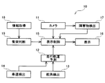
- FIG. 1 shows the configuration of a safety confirmation support apparatus 10 of this embodiment.
- the safety confirmation support apparatus 10 of the present embodiment is configured to function as an electronic control unit or an electronic control circuit. It is mounted on a vehicle (also referred to as a host vehicle or a target vehicle) and supports driver's safety confirmation.
- the safety confirmation support apparatus 10 includes a camera 11, a traveling trajectory prediction unit 12, a rudder angle detector 13, a vehicle speed detector 14, a display control unit 15, a display 16, and an obstacle detection.
- a component such as a unit 17, an information acquisition unit 18, and a collision determination unit 19 are provided. Note that these components 12 to 19 are conceptually classified by focusing on the functions of the safety confirmation support apparatus 10, and each of them does not necessarily exist physically independently.
- Each of these can be configured by various devices, electronic components, integrated circuits, computers including CPUs and memories, computer programs, or combinations thereof.
- the camera 11 is attached to the vehicle and images a predetermined imaging area set around the vehicle.
- the camera 11 of this embodiment captures a moving image.
- the traveling trajectory prediction unit 12 is connected to a steering angle detector 13 that detects a steering angle of the vehicle (an angle at which the driver turns the steering wheel) and a vehicle speed detector 14 that detects a traveling speed (vehicle speed) of the vehicle. Based on the steering angle and the vehicle speed, the traveling track of the vehicle is predicted.
- the display control unit 15 controls the display 16 that can display an image to display a photographed image of the camera 11, and the traveling trajectory predicted by the traveling trajectory prediction unit 12 passes through the photographing region of the camera 11. In this case, the traveling track is added to the captured image and displayed.
- the obstacle detection unit 17 analyzes an image captured by the camera 11 and detects an obstacle in the captured image.
- the information acquisition unit 18 acquires information on the obstacle (obstacle information) at a position different from the shooting position of the camera 11.
- the information acquisition unit 18 is a so-called radar, which emits radio waves (millimeter waves) toward a predetermined detection area set around the vehicle and receives the reflected waves to check whether there is an obstacle. Acquire the position etc. as obstacle information. Note that information is used not only as countable nouns but also as countable nouns, and a plurality of pieces of information are equivalent to a plurality of information items.
- the collision determination unit 19 determines whether or not the vehicle collides with the obstacle based on the obstacle information acquired by the information acquisition unit 18.
- the display control unit 15 of this embodiment is connected to the obstacle detection unit 17 and the collision determination unit 19 and switches the display mode of the display 16 according to the determination result of the collision determination unit 19.
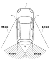
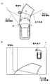
- FIG. 2 shows a shooting area of the camera 11 and a detection area of the information acquisition unit 18 (radar) set around the vehicle 1 of the present embodiment.
- a pair of left and right cameras 11 are provided on the side surface of the vehicle 1, and an area from the camera 11 toward the rear of the vehicle 1 is set as a shooting area, and includes a rear side portion of the vehicle 1.
- the vehicle 1 of the present embodiment does not have a side mirror (door mirror), but instead has a side mirror in which the area reflected on the side mirror is set as a shooting area and is shot with the camera 11. It has become.
- a pair of left and right radars as information acquisition devices 18 are provided at the rear end of the vehicle 1, and detection areas are set on the left and right rear sides of the vehicle 1, partially overlapping with the shooting area of the camera 11. Yes.
- the information acquisition unit 18 is not limited to a radar as long as it can detect the presence or absence or position of an obstacle, and may be a sonar that detects sound waves or a laser sensor that detects light.
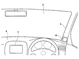
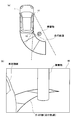
- FIG. 3 shows the indicator 16 provided in the vehicle 1 of the present embodiment.
- the display 16 is installed in a pair of left and right windows (so-called A pillars) 3 on the left and right sides of the windshield 2 (the left display 16 is not shown).
- a display screen composed of a liquid crystal display or the like is directed to the driver (driver's seat).
- the left and right of the image captured by the camera 11 are reversed and displayed on the display 16. The driver can check the rear side from the side surface of the vehicle 1 by looking at the display 16 as with the side mirror.
- the position where the display 16 is installed is not limited to the A pillar as long as it is visible from the driver's seat, and may be embedded in the left and right ends of the dashboard 4 or in the door panel, for example. Further, a photographed image of the camera 11 may be displayed using a display 5 of a car navigation system installed at substantially the center of the dashboard 4 as a display.
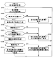
- FIG. 4 shows a flowchart of a safety confirmation support process (also referred to as a safety confirmation support method) executed by the safety confirmation support apparatus 10 (or electronic control unit) of the present embodiment.
- the described flowchart includes a plurality of sections (or referred to as steps), and each section is expressed as, for example, S110. Further, each section can be divided into a plurality of subsections, while a plurality of sections can be combined into one section.
- Each section can be referred to as a device, module, or unique name, for example, a detection section can be referred to as a detection device, detection module, detector.
- the section includes (i) not only a section of software combined with a hardware unit (eg, a computer) but also (ii) a section of hardware (eg, an integrated circuit, a wiring logic circuit) and related devices. It can be realized with or without the function.
- the hardware section can be included inside the microcomputer.
- the shift lever of the vehicle 1 is in the reverse (R) position (S102).
- the traveling track of the vehicle 1 passes through the imaging region of the camera 11, the traveling track can be added to the captured image and displayed on the display 16.
- the shift lever is not in the reverse (R) position (S102: no)
- the traveling trajectory is not added to the rear image of the vehicle 1, and the captured image of the camera 11 is reversed left and right and displayed on the display 16 as it is. It is displayed (S103).
- the driver can check the rear of the vehicle 1 with the image displayed on the display device 16 in the same manner as the side mirror.
- the reverse image is displayed on the display device 16 in this way, the process returns to the top of the safety confirmation support process, and the image data captured by the camera 11 is acquired again (S101).
- the traveling path of the vehicle 1 is predicted based on the steering angle and the vehicle speed (S104).
- the traveling track depends not only on the rudder angle but also on the vehicle speed. If the rudder angle is the same, the turning radius increases as the vehicle speed increases.
- a traveling track of a predetermined distance (for example, 1.5 vehicle length) is predicted from the rear wheel of the vehicle 1 toward the rear.
- the travel trajectory may be predicted for at least the imaging region of the camera 11.
- the image data captured by the camera 11 is analyzed to determine whether there is an obstacle in the captured image (S105).
- a person or an object included in a range where there is a possibility of colliding with the vehicle 1 when viewed from the position of the camera 11 is detected as an obstacle.
- a plurality of templates of silhouettes of various obstacles are prepared in advance, and a silhouette that matches one of the templates exists in a predetermined range (for example, a range from the vehicle 1 to 0.5 vehicle length) in the photographed image.
- An obstacle may be detected based on whether or not to do so, or an obstacle in a predetermined range may be detected by comparison (parallax) with an image taken from a position different from the camera 11.
- an obstacle may be detected (specified) from the captured image based on the obstacle information acquired by the information acquisition unit 18.
- the captured image of the camera 11 is reversed left and right and displayed on the display 16 and a guide line representing the traveling trajectory predicted in S104 is reversed. (S106).
- the driver can not only confirm the rear of the vehicle 1 on the display of the display 16 but also can register the destination of the vehicle 1 moving backward. Note that the color of the guide line displayed in S106 is set to yellow.
- the information acquisition unit 18 uses the obstacle information such as the presence or absence of the obstacle and the position thereof. (S108), and based on the obstacle information, it is determined whether or not the vehicle 1 collides with the obstacle (S109). Since the information acquisition unit 18 acquires the obstacle information at a position different from the shooting position of the camera 11, even if the information acquisition unit 18 appears to collide with the obstacle from the shooting position of the camera 11, the information acquisition unit 18 has an obstacle. From the information, it is not always determined that the vehicle collides with the obstacle, and it may be determined that the vehicle does not collide.
- the captured image of the camera 11 is reversed left and right and displayed on the display 16 and the obstacle in the image is displayed.
- the guide lines are displayed in a collision mode in which the guide lines overlap with each other (S110). Note that the color of the guide line displayed in S110 is set to red.
- the captured image of the camera 11 is reversed left and right and displayed on the display 16 and superimposed on the obstacle in the guide line.
- the guide line is displayed in a collision avoidance mode in which the portion (superimposed portion) is not displayed (S111).
- the color of the guide line displayed in S111 is set to yellow. In this way, when a reverse line is displayed with a guide line added in a display mode according to the determination result of whether or not it collides with an obstacle, the process returns to the top of the safety confirmation support process and the above-described series of processes is repeated.
- C. Guide line display example As described above, in this embodiment, it is possible to add the traveling trajectory of the vehicle 1 to the captured image of the camera 11 and display it on the display device 16, and to collide with an obstacle based on the obstacle information of the information acquisition device 18.
- a guide line (traveling trajectory) is displayed in a collision mode or a collision avoidance mode according to the determination result of whether or not to do so.
- a display example of a guide line will be described.
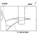
- FIG. 5 shows an example in which guide lines are displayed in a collision mode.
- the vehicle 1 moves backward while turning the handle to the right, and the traveling track passes through the imaging area of the camera 11 on the right side.
- there is an obstacle on the right rear side of the vehicle 1 and this obstacle is detected in the captured image of the camera 11 and the traveling trajectory is superposed (when viewed from the position of the camera 11, the traveling trajectory is an obstacle). (It seems to collide with).
- the obstacle behind the obstacle is a blind spot as seen from the position of the camera 11, the obstacle information at the blind spot can be acquired by the information acquisition unit 18 (radar) at the right rear end of the vehicle 1.
- radar information acquisition unit 18
- an obstacle is detected in the detection area of the information acquisition unit 18, and it is determined that the vehicle 1 collides with the obstacle.
- the display mode of the guide line (traveling trajectory) is set to the collision mode, and as shown in FIG. 5B, the display unit 16 overlaps the obstacles in the captured image (front side).
- a guide line is displayed. By doing so, it is possible to impress the driver who has seen the display device 16 that the traveling track of the vehicle 1 collides with an obstacle (cannot wrap around behind).
- the guide line is displayed in red (yellow when there is no collision), or a mark indicating a collision (collision mark) is added to the collision location. Can be emphasized.
- a distance guide line indicating a distance from the vehicle 1 is attached to the guide line of the present embodiment every predetermined distance (for example, 1 m).
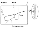
- FIG. 6 shows an example in which the guide line is displayed in a collision avoidance mode.
- the traveling track of the vehicle 1 that moves backward while turning the steering wheel to the right passes through the imaging region of the right camera 11, and the vehicle 1 Obstacles on the right rear of the camera 11 are detected in the captured image of the camera 11, and the traveling track is superimposed on the obstacle (when viewed from the position of the camera 11, the traveling track appears to collide with the obstacle).
- the information acquiring unit 18 radar
- the display mode of the guide line (traveling track) is set to the collision avoidance mode, and as shown in FIG. 6B, the display unit 16 erases the overlapping portion with the obstacle in the traveling track. (Hidden), the guide line of the non-overlapping part is displayed. In this way, by erasing the portion of the guide line that is hidden behind the obstacle and not visible, the traveling track of the vehicle 1 turns around behind the obstacle to the driver who has seen the display 16 and the obstacle. You can impress that it doesn't collide with.
- an obstacle shadow is added around the overlapping portion of the guide line and the obstacle as shown in an enlarged view in FIG.
- a light and dark gradation is applied so that the shadow becomes thinner toward the outside from the outline of the obstacle on the near side of the guide line.
- the safety confirmation support device 10 of the present embodiment when the traveling path of the vehicle 1 is added to the captured image of the camera 11 and displayed on the display 16, behind the obstacle detected in the captured image.
- Information on (dead angle) is acquired by an information acquisition unit 18 (radar) at a position different from that of the camera 11.
- the judgment result of the presence or absence of the collision between the vehicle 1 and the obstacle based on the obstacle information is reflected in the display mode of the display 16 and, in the case of a collision, the guide line is displayed in the collision mode (overlap with the obstacle).
- the guide line is displayed in a collision avoidance mode (erasing the overlapping portion with the obstacle).
- the collision avoidance mode of the guide line is not limited to this, and can be distinguished from the collision mode, as long as it is a display mode that impresses that the traveling track does not collide with the obstacle (it can go around behind the obstacle). Good.
- FIG. 8 shows an example in which the guide line is displayed in a collision avoidance manner on the display 16 of the first modified example, and the illustrated example is the same situation as (a) of FIG.
- the guide line of the portion that does not overlap the obstacle (the portion that is not hidden by the obstacle) in the traveling track is displayed as a solid line on the display 16, whereas the overlapping portion with the obstacle ( The guide line of the part hidden behind the obstacle is displayed as a broken line (hidden line).
- the driving line of the vehicle 1 is obstructed by the driver who viewed the display 16 by changing the drawing mode of the guide line between the portion that is not hidden behind the obstacle and the portion that is not visible behind the obstacle. It can be impressed that it does not collide with obstacles by going behind the object.
- the drawing mode (drawing line) of the overlapping portion is not limited to the broken line, and may be a mode that can be distinguished from the non-overlapping portion.
- the display mode of the guide line is changed according to the determination result of the presence or absence of the collision between the vehicle 1 and the obstacle based on the obstacle information of the information acquisition unit 18.
- a display based on the obstacle information of the information acquisition unit 18 is added to the display unit 16 so that the driver can grasp whether the vehicle 1 collides with the obstacle. Good.
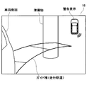
- FIG. 9 shows an example in which a guide line is displayed on the display 16 of the second modification.
- the traveling track of the vehicle 1 that moves backward while turning the handle to the right passes through the imaging region of the right camera 11, and the obstacle on the right rear of the vehicle 1 is the camera 11.
- the traveling trajectory is superimposed on the obstacle (when viewed from the position of the camera 11, the traveling trajectory appears to collide with the obstacle).
- an obstacle is detected in the detection area of the information acquisition unit 18 (radar) at the right rear end of the vehicle 1, and obstacle information such as the position and size of the obstacle is acquired.
- the traveling track and the obstacle are in a positional relationship that does not collide.
- a collision warning range that may collide with the obstacle is calculated if the traveling track is within the range.
- the left and right sides of the image captured by the camera 11 are reversed, and a guide line (traveling trajectory) is displayed on the inverted image, and the collision warning range is displayed. Is displayed.
- the driver who has seen the display unit 16 will collide with an obstacle if the guide line is in the collision warning range, and will not collide with the obstacle unless the guide line is in the collision warning range. Can show.
- FIG. 10 shows an example in which guide lines are displayed on the display 16 of the third modification.
- the illustrated example is a situation similar to (a) of FIG. 5, and is a case where it is determined that the vehicle 1 collides with an obstacle based on the obstacle information of the information acquisition unit 18.
- the display 16 displays a guide line (running trajectory) superimposed on a reversed image obtained by inverting the left and right of the image captured by the camera 11, and in addition, a warning display (characters and figures) for warning a collision is added. Is done.
- a graphic indicating the position of the collision is imitated as a warning display, imitating the vehicle 1.
- a warning display is not added, and only a guide line is displayed on the reverse image.
- the warning display of the third modification can also be applied to the above-described embodiment, the first modification, and the second modification, and the warning display when it is determined that the vehicle 1 collides with an obstacle. By adding, the collision can be further emphasized.
- FIG. 11 shows an example in which obstacle information is acquired by the safety confirmation support device 10 of the fourth modified example.
- FIG. 11A in the fourth modification example, from the rear end of the vehicle 1 separately from the camera 11 that captures the rear from the side surface of the vehicle 1 (referred to as “side camera” in the fourth modification example).
- a back camera 21 that captures the rear is provided as an information acquisition unit, and a shooting area (side shooting area) of the side camera 11 and a shooting area (back shooting area) of the back camera 21 partially overlap.
- the obstacle is included in both the side photographing region and the back photographing region, and the obstacle is determined by comparing (parallax) the photographed image of the side camera 11 and the photographed image of the back camera 21.
- Obstacle information such as the position and size of the can be acquired. Further, information behind an obstacle that becomes a blind spot when viewed from the position of the side camera 11 can be acquired from the position of the back camera 21. Therefore, even if the vehicle 1 appears to collide with an obstacle in the captured image of the side camera 11, as shown in FIG. 11B, the traveling trajectory is behind the obstacle in the captured image of the back camera 21. If it appears to pass, it can be determined that the vehicle 1 does not collide with an obstacle.
- a sonar that detects the approach of the obstacle may be used in combination. For example, if an obstacle is not detected by sonars (not shown) provided at the left and right rear ends of the vehicle 1, the vehicle 1 is captured by the back camera 21 as shown in FIG. It can be determined that the area that appears immediately after is the ground without an obstacle (ground area). Then, the ground region and a region having continuity in hue and brightness of the image are also estimated as the ground, and if the traveling path passes through the region estimated as the ground, it is determined that the vehicle 1 does not collide with the obstacle. May be.
- FIG. 12 shows an example in which obstacle information is acquired by the safety check support device 10 of the fifth modified example.
- the illustrated example is a case where the vehicle 1 is moving forward and once passes by an obstacle and then going backward. In the figure, the past position of the vehicle 1 is shown with hatching.
- the photographed image of the camera 11 is stored (recorded), and the obstacle such as the position and size of the obstacle is compared by comparing the current photographed image with the past photographed image.
- Get material information In the example shown in the figure, an obstacle is included in the current photographed image of the camera 11, but behind the obstacle is a blind spot as viewed from the current photographing position.
- the photographing position and the photographing region are different, so that information on the blind spot in the current photographed image can be acquired from the past photographed image.
- FIG. 13 shows an example in which a guide line is added to the front image of the vehicle 1 by the safety check support device 10 of the sixth modified example.
- a front camera 31 that captures the front from the front end of the vehicle 1 and a side camera 32 that captures the front from the side surface (side mirror) of the vehicle 1 are provided.
- the shooting area (front shooting area) of the front camera 31 and the shooting area (side shooting area) of the side camera 32 partially overlap.
- the photographed image of the front camera 31 is displayed on the display 5 (see FIG. 3) as a display device installed in the approximate center of the dashboard 4.
- the vehicle 1 moves forward while turning the steering wheel to the right, and the traveling track passes through the front photographing area. Further, an obstacle on the left front side of the vehicle 1 is included in both the front shooting area and the side shooting area, and the position of the obstacle is determined by comparison (parallax) between the captured image of the front camera 31 and the captured image of the side camera 32 Obstacle information such as size and size can be acquired. Since the shooting positions of the front camera 31 and the side camera 32 are different, the side camera 32 is displayed even if the vehicle 1 does not collide with the obstacle (passes through the obstacle) in the photographed image of the front camera 31. From the captured image, it may be determined that the vehicle 1 collides with an obstacle.
- the side camera 32 of the sixth modification corresponds to an information acquisition device
- the information acquisition device of the sixth modification is not limited to the side camera 32 and acquires obstacle information using a radar or sonar. May be.
- the display 5 has a guide line (traveling trajectory) superimposed on the photographed image of the front camera 31, as shown in FIG. 13 (b).
- a warning display (a graphic showing the position of the collision by imitating the vehicle 1) is added.
- a warning display is not added.
- the color of the guide line may be changed depending on whether or not the vehicle 1 and the obstacle collide. For example, the color of the guide line is red when there is a collision, and the color of the guide line is yellow when there is no collision. It may be.
- the driver can change the display mode of the display 5 (indicator) according to the determination result of the presence or absence of the collision between the vehicle 1 and the obstacle based on the captured image of the side camera 32, so that the driver can From the display, it is possible to intuitively grasp whether the vehicle 1 collides with an obstacle (whether it can pass through the front).
- the display 5 installed in the approximate center of the dashboard 4 is used as a display.
- the display is not limited to this, and a head-up display (hereinafter referred to as “HUD”) that displays a virtual image superimposed on the scenery in front of the vehicle 1 can also be used.
- HUD head-up display
- FIG. 14 shows an application example to the HUD as a display of the seventh modification.
- the illustrated example is the same situation as in FIG.
- the HUD projects an image from a HUD main body (not shown) mounted in the dashboard 4 onto a windshield (display area) 6 of the windshield 2 so that the image is superimposed on the front view seen through the windshield 2 from the driver's seat. Is displayed as a virtual image.
- the front camera 31 of the seventh modified example is adapted to take an image similar to the front scenery seen from the driver's seat.
- the display position of the traveling track in the display area 6 of the windshield 2 is determined, and an image of the guide line is projected from the HUD body.
- a guide line is displayed as a virtual image over the scenery in front.
- the warning display is added by projecting the warning display image onto the display area 6.
- a warning display is not added. In this way, the driver can intuitively determine whether the vehicle 1 collides with an obstacle (whether it can pass through the front) or not from the virtual image display that overlaps the scenery in front, as in the sixth modification. It becomes possible to grasp.
Abstract
This safety confirmation assist apparatus captures, by a camera, a prescribed imaging region set around a vehicle, predicts the travelling trajectory of the vehicle within the imaging region, and detects an obstacle from the image captured by the camera. In addition, obstacle information related to an obstacle is obtained at a different position from the imaging position by the camera, and a determination on whether or not the vehicle will collide with the obstacle is made on the basis of the obstacle information. Next, a display device visible from the driver seat in the vehicle is controlled to display the captured image to which the travelling trajectory is added, and the determination on whether or not the vehicle will collide with the obstacle is reflected in the displaying mode of the display device.
Description
本出願は、2015年3月20日に出願された日本出願番号2015-57604号に基づくもので、ここにその記載内容を援用する。
This application is based on Japanese Application No. 2015-57604 filed on March 20, 2015, the contents of which are incorporated herein by reference.
本開示は、車両の運転者の安全確認を支援する安全確認支援装置(apparatus)および安全確認支援方法(method)に関する。
The present disclosure relates to a safety confirmation support device (apparatus) and a safety confirmation support method (method) that support safety confirmation of a driver of a vehicle.
車両の運転者の安全確認を支援するために、カメラで車両の周囲を撮影した画像を車載モニターに表示する技術が開発されている。運転者は、表示された画像から周囲の障害物などを把握することができる。また、撮影した画像を表示するだけでなく、その画像内での車両の走行軌道を予側し、予測走行軌道を合わせて表示することで、運転をガイドする技術が提案されている(特許文献1)。
In order to support vehicle driver safety confirmation, a technology has been developed that displays an image of the surroundings of a vehicle on a vehicle-mounted monitor. The driver can grasp surrounding obstacles and the like from the displayed image. In addition to displaying a photographed image, a technique has been proposed that guides driving by predicting the traveling trajectory of the vehicle in the image and displaying the predicted traveling trajectory together (Patent Literature). 1).
しかし、提案されている技術では、撮影した画像に予測走行軌道を単に重ねて表示するだけなので、画像内の障害物と予測走行軌道との位置関係(障害物に衝突するのか、障害物の後ろに回り込んで衝突しないのか)を運転者が把握するのが困難な場合があり、結局、目視で確認しなければならないことがあった。
However, with the proposed technology, the predicted travel trajectory is simply superimposed on the captured image, so the positional relationship between the obstacle in the image and the predicted travel trajectory (whether it collides with the obstacle or behind the obstacle) It may be difficult for the driver to grasp whether or not the vehicle will collide with the vehicle, and eventually it must be visually confirmed.
この開示は、表示器の画像内の障害物と車両の予測走行軌道とが衝突するか否かを運転者が容易に把握することが可能な表示技術の提供を目的とする。
This disclosure is intended to provide a display technique that allows a driver to easily grasp whether or not an obstacle in an image of a display device collides with a predicted traveling trajectory of a vehicle.
本開示の例として、安全確認支援装置および安全確認支援方法は、車両の周囲に設定された所定の撮影領域をカメラで撮影し、撮影領域内における車両の走行軌道を予測すると共に、カメラの撮影画像の中から障害物を検出する。また、カメラの撮影位置とは異なる位置で、障害物に関する障害物情報を取得し、その障害物情報に基づいて、車両が障害物に衝突するか否かを判断する。そして、車両の運転席から視認可能な位置に設置された表示器を制御し、カメラの撮影画像に走行軌道を付加して表示させると共に、車両が障害物に衝突するか否かの判断結果を表示器の表示態様に反映させる。
As an example of the present disclosure, a safety confirmation support device and a safety confirmation support method capture a predetermined imaging region set around a vehicle with a camera, predict a traveling trajectory of the vehicle in the imaging region, and capture the camera An obstacle is detected from the image. Also, obstacle information related to the obstacle is acquired at a position different from the shooting position of the camera, and it is determined whether or not the vehicle collides with the obstacle based on the obstacle information. Then, a display installed at a position visible from the driver's seat of the vehicle is controlled, and a traveling track is added to the captured image of the camera for display, and a determination result as to whether the vehicle collides with an obstacle is displayed. This is reflected in the display mode of the display.
このようにカメラの撮影位置とは異なる位置で障害物情報を別途取得し、その障害物情報に基づいて判断した車両と障害物との衝突の有無に応じて表示器の表示態様を異ならせることで、運転者は、表示器の表示から直感的に車両が障害物に衝突するか否かを把握することが可能となる。結果として、障害物を目視で確認しなくてもよく、運転者の安全確認が容易となる。
In this way, obstacle information is separately acquired at a position different from the shooting position of the camera, and the display mode of the display device is made different depending on the presence or absence of a collision between the vehicle and the obstacle determined based on the obstacle information. Thus, the driver can intuitively grasp whether or not the vehicle collides with the obstacle from the display on the display. As a result, it is not necessary to visually check the obstacle, and the driver can easily check the safety.
本開示についての上記目的およびその他の目的、特徴や利点は、添付の図面を参照しながら下記の詳細な記述により、より明確になる。
本実施例の安全確認支援装置の構成を示す説明図である。
本実施例の車両の周囲に設定されたカメラの撮影領域および情報取得器(レーダー)の検知領域を示す説明図である。
本実施例の車両に設けられた表示器を示す説明図である。
本実施例の安全確認支援装置で実行される安全確認支援処理を示すフローチャートである。
本実施例の表示器にガイド線が衝突態様で表示される例を示す説明図である。
本実施例の表示器にガイド線が衝突回避態様で表示される例を示す説明図である。
本実施例の表示器でガイド線と障害物との重畳部分の周辺に障害物の影が付される例を拡大して示す説明図である。
第1変形例の表示器にガイド線が衝突回避態様で表示される例を示す説明図である。
第2変形例の表示器にガイド線が表示される例を示す説明図である。
第3変形例の表示器にガイド線が表示される例を示す説明図である。
第4変形例の安全確認支援装置で障害物情報を取得する例を示す説明図である。
第5変形例の安全確認支援装置で障害物情報を取得する例を示す説明図である。
第6変形例の安全確認支援装置で車両の前方画像にガイド線を付加する例を示す説明図である。
第7変形例の表示器としてHUDへの適用例を示す説明図である。
The above and other objects, features, and advantages of the present disclosure will become more apparent from the following detailed description with reference to the accompanying drawings.
It is explanatory drawing which shows the structure of the safety confirmation assistance apparatus of a present Example. It is explanatory drawing which shows the imaging area | region of the camera set around the vehicle of a present Example, and the detection area | region of an information acquisition device (radar). It is explanatory drawing which shows the indicator provided in the vehicle of a present Example. It is a flowchart which shows the safety confirmation assistance process performed with the safety confirmation assistance apparatus of a present Example. It is explanatory drawing which shows the example by which a guide line is displayed on the indicator of a present Example by the collision aspect. It is explanatory drawing which shows the example by which a guide line is displayed on the indicator of a present Example in a collision avoidance aspect. It is explanatory drawing which expands and shows the example by which the shadow of an obstruction is attached | subjected to the circumference | surroundings of the overlapping part of a guide line and an obstruction with the indicator of a present Example. It is explanatory drawing which shows the example by which a guide line is displayed in the collision avoidance aspect on the display of a 1st modification. It is explanatory drawing which shows the example in which a guide line is displayed on the indicator of a 2nd modification. It is explanatory drawing which shows the example in which a guide line is displayed on the indicator of a 3rd modification. It is explanatory drawing which shows the example which acquires obstruction information with the safety confirmation assistance apparatus of a 4th modification. It is explanatory drawing which shows the example which acquires obstruction information with the safety confirmation assistance apparatus of a 5th modification. It is explanatory drawing which shows the example which adds a guide line to the front image of a vehicle with the safety confirmation assistance apparatus of a 6th modification. It is explanatory drawing which shows the example applied to HUD as a display of a 7th modification.
以下では、上述した本願開示の内容を明確にするために実施例について説明する。
Hereinafter, examples will be described in order to clarify the contents of the disclosure of the present application described above.
(A.装置構成)
図1には、本実施例の安全確認支援装置10の構成が示されている。本実施例の安全確認支援装置10は、電子制御ユニットあるいは電子制御回路として機能するように構成される。車両(ホスト車両あるいは対象車両とも言及される)に搭載され、運転者の安全確認を支援する。図示されるように安全確認支援装置10は、カメラ11と、走行軌道予測部12と、舵角検出器13と、車速検出器14と、表示制御部15と、表示器16と、障害物検出部17と、情報取得器18と、衝突判断部19などの構成要素を備えている。尚、これらの構成要素12~19は、安全確認支援装置10を機能に着目して概念的に分類したものであり、それぞれが必ずしも物理的に独立して存在している必要はない。これらそれぞれは、各種の機器や、電子部品、集積回路、CPUやメモリを含むコンピューター、コンピュータープログラム、あるいはそれらの組合せなどによって構成することができる。 (A. Device configuration)
FIG. 1 shows the configuration of a safetyconfirmation support apparatus 10 of this embodiment. The safety confirmation support apparatus 10 of the present embodiment is configured to function as an electronic control unit or an electronic control circuit. It is mounted on a vehicle (also referred to as a host vehicle or a target vehicle) and supports driver's safety confirmation. As shown in the figure, the safety confirmation support apparatus 10 includes a camera 11, a traveling trajectory prediction unit 12, a rudder angle detector 13, a vehicle speed detector 14, a display control unit 15, a display 16, and an obstacle detection. A component such as a unit 17, an information acquisition unit 18, and a collision determination unit 19 are provided. Note that these components 12 to 19 are conceptually classified by focusing on the functions of the safety confirmation support apparatus 10, and each of them does not necessarily exist physically independently. Each of these can be configured by various devices, electronic components, integrated circuits, computers including CPUs and memories, computer programs, or combinations thereof.
図1には、本実施例の安全確認支援装置10の構成が示されている。本実施例の安全確認支援装置10は、電子制御ユニットあるいは電子制御回路として機能するように構成される。車両(ホスト車両あるいは対象車両とも言及される)に搭載され、運転者の安全確認を支援する。図示されるように安全確認支援装置10は、カメラ11と、走行軌道予測部12と、舵角検出器13と、車速検出器14と、表示制御部15と、表示器16と、障害物検出部17と、情報取得器18と、衝突判断部19などの構成要素を備えている。尚、これらの構成要素12~19は、安全確認支援装置10を機能に着目して概念的に分類したものであり、それぞれが必ずしも物理的に独立して存在している必要はない。これらそれぞれは、各種の機器や、電子部品、集積回路、CPUやメモリを含むコンピューター、コンピュータープログラム、あるいはそれらの組合せなどによって構成することができる。 (A. Device configuration)
FIG. 1 shows the configuration of a safety
カメラ11は、車両に取り付けられており、車両の周囲に設定された所定の撮影領域を撮影する。本実施例のカメラ11は、動画像を撮影する。 走行軌道予測部12は、車両の舵角(運転者がハンドルを切る角度)を検出する舵角検出器13や、車両の走行速度(車速)を検出する車速検出器14と接続されており、舵角および車速に基づいて、車両の走行軌道を予測する。
The camera 11 is attached to the vehicle and images a predetermined imaging area set around the vehicle. The camera 11 of this embodiment captures a moving image. The traveling trajectory prediction unit 12 is connected to a steering angle detector 13 that detects a steering angle of the vehicle (an angle at which the driver turns the steering wheel) and a vehicle speed detector 14 that detects a traveling speed (vehicle speed) of the vehicle. Based on the steering angle and the vehicle speed, the traveling track of the vehicle is predicted.
表示制御部15は、画像を表示可能な表示器16を制御して、カメラ11の撮影画像を表示させるとともに、走行軌道予測部12で予測された走行軌道がカメラ11の撮影領域内を通る場合には、走行軌道を撮影画像に付加して表示させる。 障害物検出部17は、カメラ11で撮影された画像を解析して、撮影画像内の障害物を検出する。
The display control unit 15 controls the display 16 that can display an image to display a photographed image of the camera 11, and the traveling trajectory predicted by the traveling trajectory prediction unit 12 passes through the photographing region of the camera 11. In this case, the traveling track is added to the captured image and displayed. The obstacle detection unit 17 analyzes an image captured by the camera 11 and detects an obstacle in the captured image.
情報取得器18は、カメラ11の撮影位置とは異なる位置で、障害物に関する情報(障害物情報)を取得する。本実施例の情報取得器18は、いわゆるレーダーであり、車両の周囲に設定された所定の検知領域に向けて電波(ミリ波)を照射し、その反射波を受けることで障害物の有無や位置などを障害物情報として取得する。尚、情報は、不可算名詞のみならず、可算名詞として使用され、複数の情報は、複数の情報項目と同等である。 衝突判断部19は、情報取得器18で取得された障害物情報に基づいて、車両が障害物に衝突するか否かを判断する。
The information acquisition unit 18 acquires information on the obstacle (obstacle information) at a position different from the shooting position of the camera 11. The information acquisition unit 18 according to the present embodiment is a so-called radar, which emits radio waves (millimeter waves) toward a predetermined detection area set around the vehicle and receives the reflected waves to check whether there is an obstacle. Acquire the position etc. as obstacle information. Note that information is used not only as countable nouns but also as countable nouns, and a plurality of pieces of information are equivalent to a plurality of information items. The collision determination unit 19 determines whether or not the vehicle collides with the obstacle based on the obstacle information acquired by the information acquisition unit 18.
本実施例の表示制御部15は、障害物検出部17や衝突判断部19と接続されており、衝突判断部19の判断結果に応じて表示器16の表示態様を切り換える。
The display control unit 15 of this embodiment is connected to the obstacle detection unit 17 and the collision determination unit 19 and switches the display mode of the display 16 according to the determination result of the collision determination unit 19.
図2には、本実施例の車両1の周囲に設定されたカメラ11の撮影領域および情報取得器18(レーダー)の検知領域が示されている。図示されるように車両1の側面には、カメラ11が左右一対で設けられており、このカメラ11から車両1の後方に向けた領域が撮影領域に設定され、車両1の側面後部を含んでいる。 尚、本実施例の車両1は、サイドミラー(ドアミラー)を有しておらず、その代わりとして、サイドミラーを有する場合にサイドミラーに映る領域を撮影領域に設定してカメラ11で撮影するようになっている。
FIG. 2 shows a shooting area of the camera 11 and a detection area of the information acquisition unit 18 (radar) set around the vehicle 1 of the present embodiment. As shown in the drawing, a pair of left and right cameras 11 are provided on the side surface of the vehicle 1, and an area from the camera 11 toward the rear of the vehicle 1 is set as a shooting area, and includes a rear side portion of the vehicle 1. Yes. Note that the vehicle 1 of the present embodiment does not have a side mirror (door mirror), but instead has a side mirror in which the area reflected on the side mirror is set as a shooting area and is shot with the camera 11. It has become.
また、車両1の後端には、情報取得器18としてのレーダーが左右一対で設けられており、車両1の左右の後方に検知領域が設定され、カメラ11の撮影領域と一部重複している。尚、情報取得器18は、障害物の有無や位置などを検知できれば、レーダーに限られず、音波で検知するソナーや、光で検知するレーザーセンサーであってもよい。
Further, a pair of left and right radars as information acquisition devices 18 are provided at the rear end of the vehicle 1, and detection areas are set on the left and right rear sides of the vehicle 1, partially overlapping with the shooting area of the camera 11. Yes. Note that the information acquisition unit 18 is not limited to a radar as long as it can detect the presence or absence or position of an obstacle, and may be a sonar that detects sound waves or a laser sensor that detects light.
図3には、本実施例の車両1に設けられた表示器16が示されている。図示されるように表示器16は、フロントガラス2の左右両側にある窓柱(いわゆるAピラー)3の車内側に左右一対で設置されており(左側の表示器16については図示を省略)、液晶表示器などで構成された表示画面が運転者(運転席)に向けられている。本実施例の車両1では、サイドミラーの代わりに、カメラ11で撮影した画像の左右を反転させて表示器16に表示させるようになっている。運転者は、表示器16を見ることで、サイドミラーと同様に車両1の側面から後方を確認することができる。 尚、表示器16を設置する位置は、運転席から視認可能であれば、Aピラーに限られず、例えば、ダッシュボード4の左右両端や、ドアパネルに埋め込んでおいてもよい。また、ダッシュボード4の略中央に設置されたカーナビゲーションシステムのディスプレイ5などを表示器として用いて、カメラ11の撮影画像を表示してもよい。
FIG. 3 shows the indicator 16 provided in the vehicle 1 of the present embodiment. As shown in the figure, the display 16 is installed in a pair of left and right windows (so-called A pillars) 3 on the left and right sides of the windshield 2 (the left display 16 is not shown). A display screen composed of a liquid crystal display or the like is directed to the driver (driver's seat). In the vehicle 1 of the present embodiment, instead of the side mirror, the left and right of the image captured by the camera 11 are reversed and displayed on the display 16. The driver can check the rear side from the side surface of the vehicle 1 by looking at the display 16 as with the side mirror. Note that the position where the display 16 is installed is not limited to the A pillar as long as it is visible from the driver's seat, and may be embedded in the left and right ends of the dashboard 4 or in the door panel, for example. Further, a photographed image of the camera 11 may be displayed using a display 5 of a car navigation system installed at substantially the center of the dashboard 4 as a display.
(B.安全確認支援処理)
図4には、本実施例の安全確認支援装置10(あるいは電子制御ユニット)で実行される安全確認支援処理(安全確認支援方法とも言及される)のフローチャートが示されている。 (B. Safety confirmation support processing)
FIG. 4 shows a flowchart of a safety confirmation support process (also referred to as a safety confirmation support method) executed by the safety confirmation support apparatus 10 (or electronic control unit) of the present embodiment.
記載されるフローチャートは、複数のセクション(あるいはステップと言及される)を含み、各セクションは、たとえば、S110と表現される。さらに、各セクションは、複数のサブセクションに分割されることができる、一方、複数のセクションが合わさって一つのセクションにすることも可能である。各セクションは、デバイス、モジュール、あるいは、固有名として、例えば、検出セクションは、検出デバイス、検出モジュール、ディテクタとして、言及されることができる。また、セクションは、(i)ハードウエアユニット(例えば、コンピュータ)と組み合わさったソフトウエアのセクションのみならず、(ii)ハードウエア(例えば、集積回路、配線論理回路)のセクションとして、関連する装置の機能を含みあるいは含まずに実現できる。さらに、ハードウエアのセクションは、マイクロコンピュータの内部に含まれることもできる。
The described flowchart includes a plurality of sections (or referred to as steps), and each section is expressed as, for example, S110. Further, each section can be divided into a plurality of subsections, while a plurality of sections can be combined into one section. Each section can be referred to as a device, module, or unique name, for example, a detection section can be referred to as a detection device, detection module, detector. In addition, the section includes (i) not only a section of software combined with a hardware unit (eg, a computer) but also (ii) a section of hardware (eg, an integrated circuit, a wiring logic circuit) and related devices. It can be realized with or without the function. Furthermore, the hardware section can be included inside the microcomputer.
安全確認支援処理を開始すると、まず、カメラ11で撮影した車両1の後方画像のデータを取得する(S101)。
When the safety confirmation support process is started, first, data of a rear image of the vehicle 1 taken by the camera 11 is acquired (S101).
続いて、車両1のシフトレバーが後退(R)の位置にあるか否かを判断する(S102)。前述したように本実施例では、車両1の走行軌道がカメラ11の撮影領域内を通る場合には、走行軌道を撮影画像に付加して表示器16に表示させることが可能となっている。シフトレバーが後退(R)の位置にない場合は(S102:no)、車両1の後方画像に走行軌道を付加することはなく、カメラ11の撮影画像を左右反転させて、そのまま表示器16に表示させる(S103)。これにより、運転者は、表示器16に表示される画像で、サイドミラーと同様に、車両1の後方を確認することが可能となる。こうして表示器16に反転画像を表示させると、安全確認支援処理の先頭に戻り、再びカメラ11で撮影した画像のデータを取得する(S101)。
Subsequently, it is determined whether or not the shift lever of the vehicle 1 is in the reverse (R) position (S102). As described above, in this embodiment, when the traveling track of the vehicle 1 passes through the imaging region of the camera 11, the traveling track can be added to the captured image and displayed on the display 16. When the shift lever is not in the reverse (R) position (S102: no), the traveling trajectory is not added to the rear image of the vehicle 1, and the captured image of the camera 11 is reversed left and right and displayed on the display 16 as it is. It is displayed (S103). Thereby, the driver can check the rear of the vehicle 1 with the image displayed on the display device 16 in the same manner as the side mirror. When the reverse image is displayed on the display device 16 in this way, the process returns to the top of the safety confirmation support process, and the image data captured by the camera 11 is acquired again (S101).
一方、シフトレバーが後退(R)の位置にある場合は(S102:yes)、舵角および車速に基づいて、車両1の走行軌道を予測する(S104)。走行軌道は、舵角だけでなく車速にも依存し、舵角が同じであれば、車速が速いほど旋回半径は大きくなる。本実施例では、車両1の後輪から後方に向かって所定距離(例えば、1.5車長)の走行軌道を予測する。尚、走行軌道の予測は、少なくともカメラ11の撮影領域について行えばよい。
On the other hand, when the shift lever is in the reverse (R) position (S102: yes), the traveling path of the vehicle 1 is predicted based on the steering angle and the vehicle speed (S104). The traveling track depends not only on the rudder angle but also on the vehicle speed. If the rudder angle is the same, the turning radius increases as the vehicle speed increases. In the present embodiment, a traveling track of a predetermined distance (for example, 1.5 vehicle length) is predicted from the rear wheel of the vehicle 1 toward the rear. The travel trajectory may be predicted for at least the imaging region of the camera 11.
走行軌道の予測に続いて、カメラ11で撮影した画像のデータを解析して、撮影画像内に障害物があるか否かを判断する(S105)。本実施例では、カメラ11の位置から見て車両1と衝突する可能性がある範囲に含まれる人や物を障害物として検出する。例えば、様々な障害物のシルエットのテンプレートを予め複数用意しておき、何れかのテンプレートと符合するシルエットが撮影画像の中の所定範囲(例えば、車両1から0.5車長の範囲)に存在するか否かに基づいて障害物を検出してもよいし、カメラ11とは異なる位置から撮影した画像との比較(視差)によって、所定範囲にある障害物を検出してもよい。また、情報取得器18で取得した障害物情報に基づいて、撮影画像の中から障害物を検出(特定)してもよい。
Following the prediction of the traveling trajectory, the image data captured by the camera 11 is analyzed to determine whether there is an obstacle in the captured image (S105). In this embodiment, a person or an object included in a range where there is a possibility of colliding with the vehicle 1 when viewed from the position of the camera 11 is detected as an obstacle. For example, a plurality of templates of silhouettes of various obstacles are prepared in advance, and a silhouette that matches one of the templates exists in a predetermined range (for example, a range from the vehicle 1 to 0.5 vehicle length) in the photographed image. An obstacle may be detected based on whether or not to do so, or an obstacle in a predetermined range may be detected by comparison (parallax) with an image taken from a position different from the camera 11. In addition, an obstacle may be detected (specified) from the captured image based on the obstacle information acquired by the information acquisition unit 18.
カメラ11の撮影画像内に障害物がない場合は(S105:no)、カメラ11の撮影画像を左右反転させて表示器16に表示させるとともに、S104で予測した走行軌道を表すガイド線を反転画像に重ねて表示させる(S106)。これにより、運転者は、表示器16の表示で、車両1の後方を確認できるだけでなく、車両1が後退する先の見当を付けることが可能となる。尚、S106で表示させるガイド線の色は、黄色に設定されている。
If there are no obstacles in the captured image of the camera 11 (S105: no), the captured image of the camera 11 is reversed left and right and displayed on the display 16 and a guide line representing the traveling trajectory predicted in S104 is reversed. (S106). Thereby, the driver can not only confirm the rear of the vehicle 1 on the display of the display 16 but also can register the destination of the vehicle 1 moving backward. Note that the color of the guide line displayed in S106 is set to yellow.
一方、カメラ11の撮影画像内に障害物がある場合は(S105:yes)、続いて、S104で予測した走行軌道を撮影画像に付加した場合に、画像内の障害物に走行軌道が重畳するか否か(すなわち、カメラ11の位置から見て、車両1の走行軌道が障害物に衝突するように見えるか否か)を判断する(S107)。そして、画像内の障害物に走行軌道が重畳しない場合は(S107:no)、左右反転させた画像にガイド線を重ねて表示器16に表示させる(S106)。この場合、運転者は、表示器16の表示で、車両1の走行軌道が障害物に衝突しないことを容易に把握することができる。こうして反転画像およびガイド線を表示器16に表示させると、安全確認支援処理の先頭に戻る。
On the other hand, when there is an obstacle in the captured image of the camera 11 (S105: yes), when the traveling trajectory predicted in S104 is added to the captured image, the traveling trajectory is superimposed on the obstacle in the image. (That is, whether or not the traveling track of the vehicle 1 seems to collide with an obstacle as viewed from the position of the camera 11) is determined (S107). If the traveling track does not overlap the obstacle in the image (S107: no), the guide line is superimposed on the horizontally reversed image and displayed on the display 16 (S106). In this case, the driver can easily grasp from the display on the display 16 that the traveling track of the vehicle 1 does not collide with an obstacle. When the reverse image and the guide line are displayed on the display 16 in this way, the process returns to the top of the safety confirmation support process.
これに対して、カメラ11の撮影画像内の障害物に車両1の走行軌道が重畳する場合は(S107:yes)、情報取得器18(レーダー)で障害物の有無や位置などの障害物情報を取得し(S108)、その障害物情報に基づいて、車両1が障害物に衝突するか否かを判断する(S109)。情報取得器18は、カメラ11の撮影位置とは異なる位置で障害物情報を取得するため、カメラ11の撮影位置からは障害物に衝突するように見えていても、情報取得器18の障害物情報からは必ずしも障害物に衝突すると判断されるわけではなく、衝突しないと判断される場合もある。
On the other hand, when the traveling track of the vehicle 1 is superimposed on the obstacle in the captured image of the camera 11 (S107: yes), the information acquisition unit 18 (radar) uses the obstacle information such as the presence or absence of the obstacle and the position thereof. (S108), and based on the obstacle information, it is determined whether or not the vehicle 1 collides with the obstacle (S109). Since the information acquisition unit 18 acquires the obstacle information at a position different from the shooting position of the camera 11, even if the information acquisition unit 18 appears to collide with the obstacle from the shooting position of the camera 11, the information acquisition unit 18 has an obstacle. From the information, it is not always determined that the vehicle collides with the obstacle, and it may be determined that the vehicle does not collide.
そして、障害物情報に基づいて車両1が障害物に衝突すると判断された場合は(S109:yes)、カメラ11の撮影画像を左右反転させて表示器16に表示させるとともに、画像内の障害物の上にガイド線をオーバーラップさせる衝突態様でガイド線を表示させる(S110)。尚、S110で表示させるガイド線の色は、赤色に設定されている。 一方、車両1が障害物に衝突しないと判断された場合は(S109:no)、カメラ11の撮影画像を左右反転させて表示器16に表示させるとともに、ガイド線の中で障害物と重畳する部分(重畳部分)を非表示とする衝突回避態様でガイド線を表示させる(S111)。尚、S111で表示させるガイド線の色は、黄色に設定されている。 こうして反転画像に、障害物に衝突するか否かの判断結果に応じた表示態様でガイド線を付加して表示させると、安全確認支援処理の先頭に戻って、上述した一連の処理を繰り返す。
When it is determined that the vehicle 1 collides with the obstacle based on the obstacle information (S109: yes), the captured image of the camera 11 is reversed left and right and displayed on the display 16 and the obstacle in the image is displayed. The guide lines are displayed in a collision mode in which the guide lines overlap with each other (S110). Note that the color of the guide line displayed in S110 is set to red. On the other hand, when it is determined that the vehicle 1 does not collide with an obstacle (S109: no), the captured image of the camera 11 is reversed left and right and displayed on the display 16 and superimposed on the obstacle in the guide line. The guide line is displayed in a collision avoidance mode in which the portion (superimposed portion) is not displayed (S111). Note that the color of the guide line displayed in S111 is set to yellow. In this way, when a reverse line is displayed with a guide line added in a display mode according to the determination result of whether or not it collides with an obstacle, the process returns to the top of the safety confirmation support process and the above-described series of processes is repeated.
(C.ガイド線の表示例)
前述したように本実施例では、カメラ11の撮影画像に車両1の走行軌道を付加して表示器16に表示させることが可能であり、情報取得器18の障害物情報に基づく障害物に衝突するか否かの判断結果に応じて衝突態様あるいは衝突回避態様でガイド線(走行軌道)を表示させる。以下では、ガイド線の表示例について説明する。 (C. Guide line display example)
As described above, in this embodiment, it is possible to add the traveling trajectory of thevehicle 1 to the captured image of the camera 11 and display it on the display device 16, and to collide with an obstacle based on the obstacle information of the information acquisition device 18. A guide line (traveling trajectory) is displayed in a collision mode or a collision avoidance mode according to the determination result of whether or not to do so. Hereinafter, a display example of a guide line will be described.
前述したように本実施例では、カメラ11の撮影画像に車両1の走行軌道を付加して表示器16に表示させることが可能であり、情報取得器18の障害物情報に基づく障害物に衝突するか否かの判断結果に応じて衝突態様あるいは衝突回避態様でガイド線(走行軌道)を表示させる。以下では、ガイド線の表示例について説明する。 (C. Guide line display example)
As described above, in this embodiment, it is possible to add the traveling trajectory of the
図5には、ガイド線が衝突態様で表示される例が示されている。図5の(a)に示されるように、車両1はハンドルを右に切りながら後退しており、走行軌道が右側のカメラ11の撮影領域内を通る。また、車両1の右後方には障害物があり、この障害物は、カメラ11の撮影画像内で検出されると共に、走行軌道が重畳する(カメラ11の位置から見ると、走行軌道が障害物に衝突するように見える)位置関係にある。そして、カメラ11の位置から見て障害物の背後は死角となるものの、この死角における障害物情報は車両1の右後端の情報取得器18(レーダー)によって取得することが可能であり、図5の(a)の例では、情報取得器18の検知領域で障害物が検知されて、車両1が障害物に衝突すると判断される。
FIG. 5 shows an example in which guide lines are displayed in a collision mode. As shown in FIG. 5A, the vehicle 1 moves backward while turning the handle to the right, and the traveling track passes through the imaging area of the camera 11 on the right side. Further, there is an obstacle on the right rear side of the vehicle 1, and this obstacle is detected in the captured image of the camera 11 and the traveling trajectory is superposed (when viewed from the position of the camera 11, the traveling trajectory is an obstacle). (It seems to collide with). Although the obstacle behind the obstacle is a blind spot as seen from the position of the camera 11, the obstacle information at the blind spot can be acquired by the information acquisition unit 18 (radar) at the right rear end of the vehicle 1. In the example of (a) of 5, an obstacle is detected in the detection area of the information acquisition unit 18, and it is determined that the vehicle 1 collides with the obstacle.
そのため、ガイド線(走行軌道)の表示態様は衝突態様に設定され、図5の(b)に示されるように、表示器16では、撮影画像内の障害物の上(手前)にオーバーラップさせてガイド線が表示される。こうすることで、表示器16を見た運転者に、車両1の走行軌道が障害物に衝突すること(背後に回り込めないこと)を印象付けることができる。 また、本実施例では、ガイド線が赤色(衝突しないときには黄色)で表示されたり、衝突箇所に衝突を表すマーク(衝突マーク)が付加されたりするようになっており、これらにより、衝突を更に強調することができる。 尚、本実施例のガイド線には、車両1からの距離を表す距離目安線が所定距離(例えば、1m)毎に付されている。
Therefore, the display mode of the guide line (traveling trajectory) is set to the collision mode, and as shown in FIG. 5B, the display unit 16 overlaps the obstacles in the captured image (front side). A guide line is displayed. By doing so, it is possible to impress the driver who has seen the display device 16 that the traveling track of the vehicle 1 collides with an obstacle (cannot wrap around behind). In this embodiment, the guide line is displayed in red (yellow when there is no collision), or a mark indicating a collision (collision mark) is added to the collision location. Can be emphasized. It should be noted that a distance guide line indicating a distance from the vehicle 1 is attached to the guide line of the present embodiment every predetermined distance (for example, 1 m).
一方、図6には、ガイド線が衝突回避態様で表示される例が示されている。図6の(a)に示される例では、図5の(a)と同様に、ハンドルを右に切りながら後退する車両1の走行軌道が右側のカメラ11の撮影領域内を通ると共に、車両1の右後方にある障害物がカメラ11の撮影画像内で検出され、走行軌道が障害物に重畳する(カメラ11の位置から見ると、走行軌道が障害物に衝突するように見える)位置関係にある。ただし、車両1の右後端の情報取得器18(レーダー)によると、検知領域で障害物が検知されていないことから、車両1が障害物に衝突しない(障害物の背後に回り込める)と判断される。
On the other hand, FIG. 6 shows an example in which the guide line is displayed in a collision avoidance mode. In the example shown in (a) of FIG. 6, as in (a) of FIG. 5, the traveling track of the vehicle 1 that moves backward while turning the steering wheel to the right passes through the imaging region of the right camera 11, and the vehicle 1 Obstacles on the right rear of the camera 11 are detected in the captured image of the camera 11, and the traveling track is superimposed on the obstacle (when viewed from the position of the camera 11, the traveling track appears to collide with the obstacle). is there. However, according to the information acquiring unit 18 (radar) at the right rear end of the vehicle 1, since the obstacle is not detected in the detection area, the vehicle 1 does not collide with the obstacle (can go around behind the obstacle). To be judged.
そのため、ガイド線(走行軌道)の表示態様は衝突回避態様に設定され、図6の(b)に示されるように、表示器16では、走行軌道の中で障害物との重畳部分が消去され(非表示にされ)、重畳していない部分のガイド線が表示される。このようにガイド線の中で障害物の背後に隠れて見えない部分を消去することで、表示器16を見た運転者に、車両1の走行軌道が障害物の背後に回り込んで障害物に衝突しないことを印象付けることができる。
Therefore, the display mode of the guide line (traveling track) is set to the collision avoidance mode, and as shown in FIG. 6B, the display unit 16 erases the overlapping portion with the obstacle in the traveling track. (Hidden), the guide line of the non-overlapping part is displayed. In this way, by erasing the portion of the guide line that is hidden behind the obstacle and not visible, the traveling track of the vehicle 1 turns around behind the obstacle to the driver who has seen the display 16 and the obstacle. You can impress that it doesn't collide with.
また、本実施例では、ガイド線が衝突回避態様で表示される場合、図7に拡大して示されるように、ガイド線と障害物との重畳部分の周辺に障害物の影が付されており、ガイド線よりも手前側である障害物の輪郭から外側に離れるほど影が薄くなるように明暗のグラデーションがかけられている。これにより、奥行感を出せるので、走行軌道が障害物の背後に回り込めること(障害物に衝突しないこと)を更に強調することができる。
Further, in this embodiment, when the guide line is displayed in a collision avoidance manner, an obstacle shadow is added around the overlapping portion of the guide line and the obstacle as shown in an enlarged view in FIG. In addition, a light and dark gradation is applied so that the shadow becomes thinner toward the outside from the outline of the obstacle on the near side of the guide line. Thereby, since a sense of depth can be produced, it can be further emphasized that the traveling track can go behind the obstacle (does not collide with the obstacle).
以上のように、本実施例の安全確認支援装置10では、カメラ11の撮影画像に車両1の走行軌道を付加して表示器16に表示させる場合、撮影画像内で検出される障害物の背後(死角)の情報を、カメラ11とは異なる位置の情報取得器18(レーダー)で取得する。そして、その障害物情報に基づく車両1と障害物との衝突の有無の判断結果を表示器16の表示態様に反映させ、衝突する場合はガイド線を衝突態様(障害物にオーバーラップ)で表示させるのに対し、衝突しない場合はガイド線を衝突回避態様(障害物との重畳部分を消去)で表示させるようになっている。このように表示態様を異ならせることで、運転者は、表示器16の表示から直感的に車両1が障害物に衝突するか否か(背後に回り込めるか否か)を把握することが可能となる。結果として、障害物を目視で確認しなくてもよく、安全確認が容易となる。
As described above, in the safety confirmation support device 10 of the present embodiment, when the traveling path of the vehicle 1 is added to the captured image of the camera 11 and displayed on the display 16, behind the obstacle detected in the captured image. Information on (dead angle) is acquired by an information acquisition unit 18 (radar) at a position different from that of the camera 11. And the judgment result of the presence or absence of the collision between the vehicle 1 and the obstacle based on the obstacle information is reflected in the display mode of the display 16 and, in the case of a collision, the guide line is displayed in the collision mode (overlap with the obstacle). On the other hand, when there is no collision, the guide line is displayed in a collision avoidance mode (erasing the overlapping portion with the obstacle). By changing the display mode in this way, the driver can intuitively know whether the vehicle 1 collides with an obstacle (whether it can wrap around behind) from the display on the display 16. It becomes. As a result, it is not necessary to visually check the obstacle, and safety confirmation is easy.
(D.変形例)
上述した実施例には、幾つかの変形例が存在する。以下では、これら変形例について簡単に説明する。 (D. Modification)
There are several variations in the above-described embodiment. Hereinafter, these modified examples will be briefly described.
上述した実施例には、幾つかの変形例が存在する。以下では、これら変形例について簡単に説明する。 (D. Modification)
There are several variations in the above-described embodiment. Hereinafter, these modified examples will be briefly described.
(D-1.第1変形例)
上述した実施例では、ガイド線(走行軌道)の表示態様が衝突回避態様に設定された場合、ガイド線の中で障害物との重畳部分を消去する(非表示にする)ようになっていた。しかし、ガイド線の衝突回避態様は、これに限られず、衝突態様と区別ができて、走行軌道が障害物に衝突しないこと(障害物の背後に回り込めること)を印象付ける表示態様であればよい。 (D-1. First Modification)
In the above-described embodiment, when the display mode of the guide line (traveling track) is set to the collision avoidance mode, the overlapping portion with the obstacle in the guide line is erased (not displayed). . However, the collision avoidance mode of the guide line is not limited to this, and can be distinguished from the collision mode, as long as it is a display mode that impresses that the traveling track does not collide with the obstacle (it can go around behind the obstacle). Good.
図8には、第1変形例の表示器16にガイド線が衝突回避態様で表示される例が示されており、図示した例は、図6の(a)と同様のシチュエーションである。図示されるように表示器16では、走行軌道の中で障害物に重畳しない部分(障害物に隠れない部分)のガイド線が実線で表示されるのに対して、障害物との重畳部分(障害物の背後に隠れる部分)のガイド線が破線(隠れ線)で表示される。このように障害物に隠れず見える部分と、障害物に隠れて見えない部分とでガイド線の描画態様を異ならせることで、表示器16を見た運転者に、車両1の走行軌道が障害物の背後に回り込んで障害物に衝突しないことを印象付けることができる。 尚、重畳部分の描画態様(描画線)は破線に限られず、重畳しない部分と区別できる態様であればよい。
FIG. 8 shows an example in which the guide line is displayed in a collision avoidance manner on the display 16 of the first modified example, and the illustrated example is the same situation as (a) of FIG. As shown in the figure, the guide line of the portion that does not overlap the obstacle (the portion that is not hidden by the obstacle) in the traveling track is displayed as a solid line on the display 16, whereas the overlapping portion with the obstacle ( The guide line of the part hidden behind the obstacle is displayed as a broken line (hidden line). In this way, the driving line of the vehicle 1 is obstructed by the driver who viewed the display 16 by changing the drawing mode of the guide line between the portion that is not hidden behind the obstacle and the portion that is not visible behind the obstacle. It can be impressed that it does not collide with obstacles by going behind the object. In addition, the drawing mode (drawing line) of the overlapping portion is not limited to the broken line, and may be a mode that can be distinguished from the non-overlapping portion.
(D-2.第2変形例)
前述した実施例では、情報取得器18の障害物情報に基づく車両1と障害物との衝突の有無の判断結果に応じてガイド線の表示態様を異ならせていた。しかし、ガイド線とは別に、情報取得器18の障害物情報に基づく表示を表示器16に付加することで、車両1が障害物に衝突するか否かを運転者に把握させるようにしてもよい。 (D-2. Second Modification)
In the above-described embodiment, the display mode of the guide line is changed according to the determination result of the presence or absence of the collision between thevehicle 1 and the obstacle based on the obstacle information of the information acquisition unit 18. However, in addition to the guide line, a display based on the obstacle information of the information acquisition unit 18 is added to the display unit 16 so that the driver can grasp whether the vehicle 1 collides with the obstacle. Good.
前述した実施例では、情報取得器18の障害物情報に基づく車両1と障害物との衝突の有無の判断結果に応じてガイド線の表示態様を異ならせていた。しかし、ガイド線とは別に、情報取得器18の障害物情報に基づく表示を表示器16に付加することで、車両1が障害物に衝突するか否かを運転者に把握させるようにしてもよい。 (D-2. Second Modification)
In the above-described embodiment, the display mode of the guide line is changed according to the determination result of the presence or absence of the collision between the
図9には、第2変形例の表示器16にガイド線が表示される例が示されている。図9の(a)に示されるように、ハンドルを右に切りながら後退する車両1の走行軌道が右側のカメラ11の撮影領域内を通ると共に、車両1の右後方にある障害物がカメラ11の撮影画像内で検出され、走行軌道が障害物に重畳する(カメラ11の位置から見ると、走行軌道が障害物に衝突するように見える)位置関係にある。また、車両1の右後端の情報取得器18(レーダー)の検知領域で障害物が検知され、障害物の位置や大きさなどの障害物情報が取得される。図9の(a)の例では、走行軌道と障害物とが衝突しない位置関係にある。そして、第2変形例では、障害物情報に基づいて、仮に走行軌道が範囲内に入っていると障害物に衝突してしまう可能性がある衝突警戒範囲を算出する。
FIG. 9 shows an example in which a guide line is displayed on the display 16 of the second modification. As shown in FIG. 9A, the traveling track of the vehicle 1 that moves backward while turning the handle to the right passes through the imaging region of the right camera 11, and the obstacle on the right rear of the vehicle 1 is the camera 11. The traveling trajectory is superimposed on the obstacle (when viewed from the position of the camera 11, the traveling trajectory appears to collide with the obstacle). Also, an obstacle is detected in the detection area of the information acquisition unit 18 (radar) at the right rear end of the vehicle 1, and obstacle information such as the position and size of the obstacle is acquired. In the example of FIG. 9A, the traveling track and the obstacle are in a positional relationship that does not collide. In the second modified example, based on the obstacle information, a collision warning range that may collide with the obstacle is calculated if the traveling track is within the range.
表示器16では、図9の(b)に示されるように、カメラ11の撮影画像の左右を反転させて、その反転画像にガイド線(走行軌道)が重ねて表示されると共に、衝突警戒範囲が表示される。こうすることで、表示器16を見た運転者に、ガイド線が衝突警戒範囲に入っていれば障害物に衝突し、ガイド線が衝突警戒範囲に入っていなければ障害物に衝突しないことを示すことができる。
In the display device 16, as shown in FIG. 9B, the left and right sides of the image captured by the camera 11 are reversed, and a guide line (traveling trajectory) is displayed on the inverted image, and the collision warning range is displayed. Is displayed. By doing so, the driver who has seen the display unit 16 will collide with an obstacle if the guide line is in the collision warning range, and will not collide with the obstacle unless the guide line is in the collision warning range. Can show.
(D-3.第3変形例)
図10には、第3変形例の表示器16にガイド線が表示される例が示されている。図示した例は、図5の(a)と同様のシチュエーションであり、情報取得器18の障害物情報に基づいて車両1が障害物に衝突すると判断された場合である。 表示器16では、カメラ11の撮影画像の左右を反転させた反転画像に重ねてガイド線(走行軌道)が表示され、それに加えて、衝突を警告するための警告表示(文字や図形)が付加される。図示した例では、車両1を模して衝突の位置を示す図形が警告表示として付加されている。 一方、車両1が障害物に衝突しないと判断された場合は、警告表示が付加されず、反転画像に重ねてガイド線が表示されるだけである。 (D-3. Third Modification)
FIG. 10 shows an example in which guide lines are displayed on thedisplay 16 of the third modification. The illustrated example is a situation similar to (a) of FIG. 5, and is a case where it is determined that the vehicle 1 collides with an obstacle based on the obstacle information of the information acquisition unit 18. The display 16 displays a guide line (running trajectory) superimposed on a reversed image obtained by inverting the left and right of the image captured by the camera 11, and in addition, a warning display (characters and figures) for warning a collision is added. Is done. In the illustrated example, a graphic indicating the position of the collision is imitated as a warning display, imitating the vehicle 1. On the other hand, when it is determined that the vehicle 1 does not collide with an obstacle, a warning display is not added, and only a guide line is displayed on the reverse image.
図10には、第3変形例の表示器16にガイド線が表示される例が示されている。図示した例は、図5の(a)と同様のシチュエーションであり、情報取得器18の障害物情報に基づいて車両1が障害物に衝突すると判断された場合である。 表示器16では、カメラ11の撮影画像の左右を反転させた反転画像に重ねてガイド線(走行軌道)が表示され、それに加えて、衝突を警告するための警告表示(文字や図形)が付加される。図示した例では、車両1を模して衝突の位置を示す図形が警告表示として付加されている。 一方、車両1が障害物に衝突しないと判断された場合は、警告表示が付加されず、反転画像に重ねてガイド線が表示されるだけである。 (D-3. Third Modification)
FIG. 10 shows an example in which guide lines are displayed on the
こうすることで、表示器16を見た運転者に、警告表示が付いていれば障害物に衝突し、警告表示が付いていなければ障害物に衝突しないことを示すことができる。 尚、第3変形例の警告表示は、前述した実施例や第1変形例や第2変形例にも適用することが可能であり、車両1が障害物に衝突すると判断された場合に警告表示を付加することで、衝突を更に強調することができる。
By doing this, it is possible to indicate to the driver who has seen the display 16 that the vehicle collides with the obstacle if the warning display is attached and does not collide with the obstacle if the warning display is not attached. The warning display of the third modification can also be applied to the above-described embodiment, the first modification, and the second modification, and the warning display when it is determined that the vehicle 1 collides with an obstacle. By adding, the collision can be further emphasized.
(D-4.第4変形例)
前述した実施例では、情報取得器18としてレーダーを用いていたが、レーダーに代えて、カメラを用いて障害物情報を取得してもよい。 図11には、第4変形例の安全確認支援装置10で障害物情報を取得する例が示されている。図11の(a)に示されるように第4変形例では、車両1の側面から後方を撮影するカメラ11(第4変形例では「サイドカメラ」という)とは別に、車両1の後端から後方を撮影するバックカメラ21が情報取得器として設けられており、サイドカメラ11の撮影領域(サイド撮影領域)と、バックカメラ21の撮影領域(バック撮影領域)とが一部重複している。 (D-4. Fourth Modification)
In the above-described embodiment, a radar is used as theinformation acquisition unit 18; however, obstacle information may be acquired using a camera instead of the radar. FIG. 11 shows an example in which obstacle information is acquired by the safety confirmation support device 10 of the fourth modified example. As shown in FIG. 11A, in the fourth modification example, from the rear end of the vehicle 1 separately from the camera 11 that captures the rear from the side surface of the vehicle 1 (referred to as “side camera” in the fourth modification example). A back camera 21 that captures the rear is provided as an information acquisition unit, and a shooting area (side shooting area) of the side camera 11 and a shooting area (back shooting area) of the back camera 21 partially overlap.
前述した実施例では、情報取得器18としてレーダーを用いていたが、レーダーに代えて、カメラを用いて障害物情報を取得してもよい。 図11には、第4変形例の安全確認支援装置10で障害物情報を取得する例が示されている。図11の(a)に示されるように第4変形例では、車両1の側面から後方を撮影するカメラ11(第4変形例では「サイドカメラ」という)とは別に、車両1の後端から後方を撮影するバックカメラ21が情報取得器として設けられており、サイドカメラ11の撮影領域(サイド撮影領域)と、バックカメラ21の撮影領域(バック撮影領域)とが一部重複している。 (D-4. Fourth Modification)
In the above-described embodiment, a radar is used as the
図11の(a)の例では、障害物がサイド撮影領域およびバック撮影領域の両方に含まれており、サイドカメラ11の撮影画像とバックカメラ21の撮影画像との比較(視差)によって障害物の位置や大きさなどの障害物情報を取得することができる。また、サイドカメラ11の位置から見て死角となる障害物の背後の情報を、バックカメラ21の位置から取得することができる。そのため、サイドカメラ11の撮影画像では車両1が障害物に衝突するように見えても、図11の(b)に示されるように、バックカメラ21の撮影画像で障害物の背後を走行軌道が通過するように見えれば、車両1が障害物に衝突しないと判断することができる。
In the example of FIG. 11A, the obstacle is included in both the side photographing region and the back photographing region, and the obstacle is determined by comparing (parallax) the photographed image of the side camera 11 and the photographed image of the back camera 21. Obstacle information such as the position and size of the can be acquired. Further, information behind an obstacle that becomes a blind spot when viewed from the position of the side camera 11 can be acquired from the position of the back camera 21. Therefore, even if the vehicle 1 appears to collide with an obstacle in the captured image of the side camera 11, as shown in FIG. 11B, the traveling trajectory is behind the obstacle in the captured image of the back camera 21. If it appears to pass, it can be determined that the vehicle 1 does not collide with an obstacle.
尚、バックカメラ21の撮影画像から車両1が障害物に衝突するか否かを判断する際には、障害物の接近を検知するソナーを併用してもよい。例えば、車両1の左右の後端に設けられたソナー(図示せず)で障害物が検知されていなければ、図11の(b)に示されるように、バックカメラ21の撮影画像で車両1の直後に映る領域は、障害物のない地面である(地面領域)と判断することができる。そして、地面領域と画像の色相や明度などで連続性のある領域を同じく地面と推定し、その地面と推定された領域を走行軌道が通っていれば、車両1が障害物に衝突しないと判断してもよい。
In addition, when determining whether the vehicle 1 collides with an obstacle from the photographed image of the back camera 21, a sonar that detects the approach of the obstacle may be used in combination. For example, if an obstacle is not detected by sonars (not shown) provided at the left and right rear ends of the vehicle 1, the vehicle 1 is captured by the back camera 21 as shown in FIG. It can be determined that the area that appears immediately after is the ground without an obstacle (ground area). Then, the ground region and a region having continuity in hue and brightness of the image are also estimated as the ground, and if the traveling path passes through the region estimated as the ground, it is determined that the vehicle 1 does not collide with the obstacle. May be.
(D-5.第5変形例)
前述した実施例では、カメラ11とは別に、情報取得器18を設けていたが、カメラ11を情報取得器として流用することも可能である。 図12には、第5変形例の安全確認支援装置10で障害物情報を取得する例が示されている。図示した例は、車両1が前進して障害物の横を一旦通り過ぎた後で、後退しようとしている場合である。図では、車両1の過去の位置がハッチングを付して示されている。 (D-5. Fifth Modification)
In the above-described embodiment, theinformation acquisition unit 18 is provided separately from the camera 11, but the camera 11 can also be used as an information acquisition unit. FIG. 12 shows an example in which obstacle information is acquired by the safety check support device 10 of the fifth modified example. The illustrated example is a case where the vehicle 1 is moving forward and once passes by an obstacle and then going backward. In the figure, the past position of the vehicle 1 is shown with hatching.
前述した実施例では、カメラ11とは別に、情報取得器18を設けていたが、カメラ11を情報取得器として流用することも可能である。 図12には、第5変形例の安全確認支援装置10で障害物情報を取得する例が示されている。図示した例は、車両1が前進して障害物の横を一旦通り過ぎた後で、後退しようとしている場合である。図では、車両1の過去の位置がハッチングを付して示されている。 (D-5. Fifth Modification)
In the above-described embodiment, the
第5変形例では、カメラ11の撮影画像を記憶(録画)しておくようになっており、現在の撮影画像と過去の撮影画像とを比較することによって障害物の位置や大きさなどの障害物情報を取得する。 図示した例では、カメラ11の現在の撮影画像内に障害物が含まれるものの、現在の撮影位置から見て障害物の背後は死角となる。一方、過去の撮影画像は、同じカメラ11であっても、撮影位置や撮影領域が異なることから、現在の撮影画像における死角の情報を過去の撮影画像から取得することができる。
In the fifth modified example, the photographed image of the camera 11 is stored (recorded), and the obstacle such as the position and size of the obstacle is compared by comparing the current photographed image with the past photographed image. Get material information. In the example shown in the figure, an obstacle is included in the current photographed image of the camera 11, but behind the obstacle is a blind spot as viewed from the current photographing position. On the other hand, even if the past photographed image is the same camera 11, the photographing position and the photographing region are different, so that information on the blind spot in the current photographed image can be acquired from the past photographed image.
(D-6.第6変形例)
前述した実施例では、車両1の後退時を想定して、主に後方確認のために後方画像にガイド線(走行軌道)を付加する場合について説明したが、これに限られるものではなく、車両周辺の確認に適用することができる。 (D-6. Sixth Modification)
In the above-described embodiment, the case where a guide line (traveling track) is added to a rear image mainly for backward confirmation on the assumption that thevehicle 1 is moving backward is described. However, the present invention is not limited to this. It can be applied to check the surroundings.
前述した実施例では、車両1の後退時を想定して、主に後方確認のために後方画像にガイド線(走行軌道)を付加する場合について説明したが、これに限られるものではなく、車両周辺の確認に適用することができる。 (D-6. Sixth Modification)
In the above-described embodiment, the case where a guide line (traveling track) is added to a rear image mainly for backward confirmation on the assumption that the
図13には、第6変形例の安全確認支援装置10で車両1の前方画像にガイド線を付加する例が示されている。図13の(a)に示されるように第6変形例では、車両1の前端から前方を撮影するフロントカメラ31と、車両1の側面(サイドミラー)から前方を撮影するサイドカメラ32とが設けられており、フロントカメラ31の撮影領域(フロント撮影領域)と、サイドカメラ32の撮影領域(サイド撮影領域)とが一部重複している。そして、フロントカメラ31の撮影画像を、ダッシュボード4の略中央に設置された表示器としてのディスプレイ5(図3参照)に表示させる。
FIG. 13 shows an example in which a guide line is added to the front image of the vehicle 1 by the safety check support device 10 of the sixth modified example. As shown in FIG. 13A, in the sixth modification, a front camera 31 that captures the front from the front end of the vehicle 1 and a side camera 32 that captures the front from the side surface (side mirror) of the vehicle 1 are provided. Thus, the shooting area (front shooting area) of the front camera 31 and the shooting area (side shooting area) of the side camera 32 partially overlap. Then, the photographed image of the front camera 31 is displayed on the display 5 (see FIG. 3) as a display device installed in the approximate center of the dashboard 4.
図13の(a)の例では、車両1がハンドルを右に切りながら前進しており、走行軌道がフロント撮影領域内を通る。また、車両1の左前方の障害物がフロント撮影領域およびサイド撮影領域の両方に含まれており、フロントカメラ31の撮影画像とサイドカメラ32の撮影画像との比較(視差)によって障害物の位置や大きさなどの障害物情報を取得することができる。そして、フロントカメラ31とサイドカメラ32とでは撮影位置が異なるため、フロントカメラ31の撮影画像では車両1が障害物に衝突しない(障害物の手前をすり抜けられる)ように見えても、サイドカメラ32の撮影画像からは車両1が障害物に衝突すると判断される場合があり、図示した例では、衝突すると判断された場合である。 尚、第6変形例のサイドカメラ32は、情報取得器に相当しているが、第6変形例の情報取得器は、サイドカメラ32に限られず、レーダーやソナーを用いて障害物情報を取得してもよい。
In the example of FIG. 13 (a), the vehicle 1 moves forward while turning the steering wheel to the right, and the traveling track passes through the front photographing area. Further, an obstacle on the left front side of the vehicle 1 is included in both the front shooting area and the side shooting area, and the position of the obstacle is determined by comparison (parallax) between the captured image of the front camera 31 and the captured image of the side camera 32 Obstacle information such as size and size can be acquired. Since the shooting positions of the front camera 31 and the side camera 32 are different, the side camera 32 is displayed even if the vehicle 1 does not collide with the obstacle (passes through the obstacle) in the photographed image of the front camera 31. From the captured image, it may be determined that the vehicle 1 collides with an obstacle. In the illustrated example, it is determined that the vehicle 1 has collided. Although the side camera 32 of the sixth modification corresponds to an information acquisition device, the information acquisition device of the sixth modification is not limited to the side camera 32 and acquires obstacle information using a radar or sonar. May be.
そして、車両1が障害物に衝突すると判断されたことに基づいて、ディスプレイ5では、図13の(b)に示されるように、フロントカメラ31の撮影画像に重ねてガイド線(走行軌道)が表示され、それに加えて、警告表示(車両1を模して衝突の位置を示す図形)が付加される。 これに対して、車両1が障害物に衝突しないと判断された場合は、警告表示が付加されない。 尚、車両1と障害物との衝突の有無に応じてガイド線の色を変更してもよく、例えば、衝突する場合はガイド線の色を赤色にし、衝突しない場合はガイド線の色を黄色にしてもよい。
Then, based on the determination that the vehicle 1 collides with the obstacle, the display 5 has a guide line (traveling trajectory) superimposed on the photographed image of the front camera 31, as shown in FIG. 13 (b). In addition to this, a warning display (a graphic showing the position of the collision by imitating the vehicle 1) is added. On the other hand, when it is determined that the vehicle 1 does not collide with an obstacle, a warning display is not added. Note that the color of the guide line may be changed depending on whether or not the vehicle 1 and the obstacle collide. For example, the color of the guide line is red when there is a collision, and the color of the guide line is yellow when there is no collision. It may be.
このように、サイドカメラ32の撮影画像に基づく車両1と障害物との衝突の有無の判断結果に応じてディスプレイ5(表示器)の表示態様を異ならせることで、運転者は、ディスプレイ5の表示から直感的に車両1が障害物に衝突するか否か(手前をすり抜けられるか否か)を把握することが可能となる。
Thus, the driver can change the display mode of the display 5 (indicator) according to the determination result of the presence or absence of the collision between the vehicle 1 and the obstacle based on the captured image of the side camera 32, so that the driver can From the display, it is possible to intuitively grasp whether the vehicle 1 collides with an obstacle (whether it can pass through the front).
(D-7.第7変形例)
上述した第6変形例では、ダッシュボード4の略中央に設置のディスプレイ5を表示器として用いていた。しかし、表示器は、これに限らず、車両1の前方の景色に重ねて画像を虚像表示するヘッドアップディスプレイ(以下、HUD)を用いることも可能である。 (D-7. Seventh Modification)
In the sixth modified example described above, thedisplay 5 installed in the approximate center of the dashboard 4 is used as a display. However, the display is not limited to this, and a head-up display (hereinafter referred to as “HUD”) that displays a virtual image superimposed on the scenery in front of the vehicle 1 can also be used.
上述した第6変形例では、ダッシュボード4の略中央に設置のディスプレイ5を表示器として用いていた。しかし、表示器は、これに限らず、車両1の前方の景色に重ねて画像を虚像表示するヘッドアップディスプレイ(以下、HUD)を用いることも可能である。 (D-7. Seventh Modification)
In the sixth modified example described above, the
図14には、第7変形例の表示器としてHUDへの適用例が示されている。図示した例は、図13の(a)と同様のシチュエーションである。HUDは、ダッシュボード4内に搭載された図示しないHUD本体からフロントガラス2のウインドシールド(表示領域)6に画像を投影することで、運転席からフロントガラス2を通して見える前方の景色に重ねて画像を虚像表示する。また、第7変形例のフロントカメラ31は、運転席から見える前方の景色と同様の画像を撮影するようになっている。
FIG. 14 shows an application example to the HUD as a display of the seventh modification. The illustrated example is the same situation as in FIG. The HUD projects an image from a HUD main body (not shown) mounted in the dashboard 4 onto a windshield (display area) 6 of the windshield 2 so that the image is superimposed on the front view seen through the windshield 2 from the driver's seat. Is displayed as a virtual image. Further, the front camera 31 of the seventh modified example is adapted to take an image similar to the front scenery seen from the driver's seat.
そして、フロントカメラ31の撮影画像内における走行軌道の位置関係に基づいて、フロントガラス2の表示領域6内における走行軌道の表示位置を決定し、HUD本体からガイド線の画像を投影することで、前方の景色に重ねてガイド線を虚像表示する。 このとき、サイドカメラ32の撮影画像に基づいて車両1が障害物に衝突すると判断された場合は、警告表示の画像を合わせ表示領域6に投影することで、警告表示が付加される。一方、車両1が障害物に衝突しないと判断された場合は、警告表示が付加されない。 このようにすれば、運転者は、前方の景色に重なる虚像表示から、第6変形例と同様に、車両1が障害物に衝突するか否か(手前をすり抜けられるか否か)を直感的に把握することが可能となる。
Then, based on the positional relationship of the traveling track in the photographed image of the front camera 31, the display position of the traveling track in the display area 6 of the windshield 2 is determined, and an image of the guide line is projected from the HUD body. A guide line is displayed as a virtual image over the scenery in front. At this time, if it is determined that the vehicle 1 collides with an obstacle based on the image taken by the side camera 32, the warning display is added by projecting the warning display image onto the display area 6. On the other hand, when it is determined that the vehicle 1 does not collide with an obstacle, a warning display is not added. In this way, the driver can intuitively determine whether the vehicle 1 collides with an obstacle (whether it can pass through the front) or not from the virtual image display that overlaps the scenery in front, as in the sixth modification. It becomes possible to grasp.
本開示は、実施例に準拠して記述されたが、本開示は当該実施例や構造に限定されるものではないと理解される。本開示は、様々な変形例や均等範囲内の変形をも包含する。加えて、様々な組み合わせや形態、さらには、それらに一要素のみ、それ以上、あるいはそれ以下、を含む他の組み合わせや形態をも、本開示の範疇や思想範囲に入るものである。
Although the present disclosure has been described with reference to the embodiments, it is understood that the present disclosure is not limited to the embodiments and structures. The present disclosure includes various modifications and modifications within the equivalent range. In addition, various combinations and forms, as well as other combinations and forms including only one element, more or less, are within the scope and spirit of the present disclosure.
Although the present disclosure has been described with reference to the embodiments, it is understood that the present disclosure is not limited to the embodiments and structures. The present disclosure includes various modifications and modifications within the equivalent range. In addition, various combinations and forms, as well as other combinations and forms including only one element, more or less, are within the scope and spirit of the present disclosure.
Claims (6)
- 車両の運転者の安全確認を支援する安全確認支援装置(10)であって、
前記車両の周囲に設定された所定の撮影領域を撮影するカメラ(11)と、
前記撮影領域内における前記車両の走行軌道を予測する走行軌道予測部(12)と、
前記カメラの撮影画像の中から障害物を検出する障害物検出部(17)と、
前記カメラの撮影位置とは異なる位置で、前記障害物に関する障害物情報を取得する情報取得器(18)と、
前記障害物情報に基づいて、前記車両が前記障害物に衝突するか否かを判断する衝突判断部(19)と、
前記車両の運転席から視認可能な位置に設置された表示器(16)と、
前記表示器を制御し、前記カメラの撮影画像に前記走行軌道を付加して表示させると共に、前記衝突判断部の判断結果を該表示器の表示態様に反映させる表示制御部(15)と
を備える安全確認支援装置。 A safety confirmation support device (10) for supporting safety confirmation of a driver of a vehicle,
A camera (11) for photographing a predetermined photographing region set around the vehicle;
A travel trajectory prediction unit (12) for predicting the travel trajectory of the vehicle in the imaging region;
An obstacle detection unit (17) for detecting an obstacle from a photographed image of the camera;
An information acquisition unit (18) for acquiring obstacle information relating to the obstacle at a position different from the shooting position of the camera;
A collision determination unit (19) for determining whether or not the vehicle collides with the obstacle based on the obstacle information;
An indicator (16) installed at a position visible from the driver's seat of the vehicle;
A display control unit (15) for controlling the display unit, adding the traveling trajectory to the captured image of the camera and displaying the same, and reflecting a determination result of the collision determination unit on a display mode of the display unit; Safety confirmation support device. - 請求項1に記載の安全確認支援装置であって、
前記表示制御部は、前記撮影画像内の前記障害物に前記走行軌道が重畳する重畳部分が存在する場合に、前記衝突判断部によって衝突しないと判断されると、前記走行軌道のうち前記重畳部分を非表示にさせる
安全確認支援装置。 The safety confirmation support device according to claim 1,
When the collision determination unit determines that the display control unit does not collide when the overlapping portion where the traveling track overlaps the obstacle in the captured image, the overlapping portion of the traveling track Safety confirmation support device that hides. - 請求項1に記載の安全確認支援装置であって、
前記表示制御部は、前記撮影画像内の前記障害物に前記走行軌道が重畳する重畳部分が存在する場合に、前記衝突判断部によって衝突しないと判断されると、前記走行軌道のうち前記重畳部分を他の部分とは態様の異なる描画線で表示させる
安全確認支援装置。 The safety confirmation support device according to claim 1,
When the collision determination unit determines that the display control unit does not collide when the overlapping portion where the traveling track overlaps the obstacle in the captured image, the overlapping portion of the traveling track A safety confirmation support device that displays a drawing line with a different aspect from other parts. - 請求項1に記載の安全確認支援装置であって、
前記表示制御部は、前記走行軌道が範囲内に入っていると前記車両が前記障害物に衝突することを表す衝突警戒範囲を、前記走行軌道と共に前記撮影画像に付加して前記表示器に表示させる
安全確認支援装置。 The safety confirmation support device according to claim 1,
The display control unit adds a collision warning range indicating that the vehicle collides with the obstacle when the traveling track is within the range, along with the traveling track, to the captured image and displays the collision warning range on the display unit. Let safety confirmation support device. - 請求項1ないし請求項4の何れか一項に記載の安全確認支援装置であって、
前記表示制御部は、前記衝突判断部によって衝突すると判断されると、該衝突を警告するための文字または図形を、前記走行軌道と共に前記撮影画像に付加して前記表示器に表示させる
安全確認支援装置。 The safety confirmation support device according to any one of claims 1 to 4,
When the collision determination unit determines that the collision has occurred, the display control unit adds a character or a graphic for warning the collision together with the traveling trajectory to the captured image and displays it on the display unit. apparatus. - 車両の運転者の安全確認を支援する安全確認支援方法であって、
前記車両の周囲に設定された所定の撮影領域をカメラで撮影する撮影工程(S101)と、
前記撮影領域における前記車両の走行軌道を予測する走行軌道予測工程(S104)と、
前記カメラの撮影画像の中から障害物を検出する障害物検出工程(S105)と、
前記カメラの撮影位置とは異なる位置で、前記障害物に関する障害物情報を取得する情報取得工程(S108)と、
前記障害物情報に基づいて、前記車両が前記障害物に衝突するか否かを判断する衝突判断工程(S109)と、
前記車両の運転席から視認可能な位置に設置された表示器を制御し、前記カメラの撮影画像に前記走行軌道を付加して表示させると共に、前記衝突判断工程の判断結果を該表示部の表示態様に反映させる表示制御工程(S106,S110,S111)と
を備える安全確認支援方法。
A safety confirmation support method for supporting safety confirmation of a vehicle driver,
A photographing step (S101) of photographing a predetermined photographing region set around the vehicle with a camera;
A travel trajectory prediction step (S104) for predicting the travel trajectory of the vehicle in the imaging region;
An obstacle detection step (S105) for detecting an obstacle from a photographed image of the camera;
An information acquisition step (S108) for acquiring obstacle information relating to the obstacle at a position different from the shooting position of the camera;
A collision determination step (S109) for determining whether or not the vehicle collides with the obstacle based on the obstacle information;
The indicator installed at a position visible from the driver's seat of the vehicle is controlled to display the image taken by the camera with the traveling track added thereto, and the determination result of the collision determination step is displayed on the display unit. A safety confirmation support method comprising: a display control step (S106, S110, S111) to be reflected in the aspect.
Applications Claiming Priority (2)
| Application Number | Priority Date | Filing Date | Title |
|---|---|---|---|
| JP2015057604A JP2016175549A (en) | 2015-03-20 | 2015-03-20 | Safety confirmation support device, safety confirmation support method |
| JP2015-057604 | 2015-03-20 |
Publications (1)
| Publication Number | Publication Date |
|---|---|
| WO2016152000A1 true WO2016152000A1 (en) | 2016-09-29 |
Family
ID=56977157
Family Applications (1)
| Application Number | Title | Priority Date | Filing Date |
|---|---|---|---|
| PCT/JP2016/000740 WO2016152000A1 (en) | 2015-03-20 | 2016-02-12 | Safety confirmation assist apparatus, safety confirmation assist method |
Country Status (2)
| Country | Link |
|---|---|
| JP (1) | JP2016175549A (en) |
| WO (1) | WO2016152000A1 (en) |
Cited By (4)
| Publication number | Priority date | Publication date | Assignee | Title |
|---|---|---|---|---|
| CN109747539A (en) * | 2017-11-08 | 2019-05-14 | 丰田自动车株式会社 | Electronics mirror device |
| CN111348055A (en) * | 2018-12-20 | 2020-06-30 | 阿里巴巴集团控股有限公司 | Driving assistance method, driving assistance system, computing device, and storage medium |
| CN113615165A (en) * | 2019-03-25 | 2021-11-05 | 松下知识产权经营株式会社 | Image generation device, camera, display system, and vehicle |
| WO2022226837A1 (en) * | 2021-04-28 | 2022-11-03 | 深圳元戎启行科技有限公司 | Time and space learning-based method and apparatus for predicting trajectory, and computer device |
Families Citing this family (2)
| Publication number | Priority date | Publication date | Assignee | Title |
|---|---|---|---|---|
| JP7050827B2 (en) * | 2018-02-19 | 2022-04-08 | 三菱電機株式会社 | Driving support device and video display method |
| JP7273084B2 (en) * | 2021-03-22 | 2023-05-12 | 名古屋電機工業株式会社 | Obstacle detection device, obstacle detection method and program |
Citations (3)
| Publication number | Priority date | Publication date | Assignee | Title |
|---|---|---|---|---|
| JP2005045602A (en) * | 2003-07-23 | 2005-02-17 | Matsushita Electric Works Ltd | Field of view monitor system for vehicle |
| JP2005078414A (en) * | 2003-09-01 | 2005-03-24 | Denso Corp | Vehicle travel support device |
| JP2013177067A (en) * | 2012-02-28 | 2013-09-09 | Aisin Seiki Co Ltd | Vehicle driving supporting device |
Family Cites Families (8)
| Publication number | Priority date | Publication date | Assignee | Title |
|---|---|---|---|---|
| JP4765213B2 (en) * | 2001-07-19 | 2011-09-07 | 日産自動車株式会社 | Parking assistance device for vehicles |
| JP3972661B2 (en) * | 2002-01-21 | 2007-09-05 | 日産自動車株式会社 | Driving assistance device |
| JP2005236540A (en) * | 2004-02-18 | 2005-09-02 | Matsushita Electric Ind Co Ltd | On-vehicle camera device |
| JP2007043530A (en) * | 2005-08-04 | 2007-02-15 | Nissan Motor Co Ltd | Drive support device and drive support method |
| JP2011161935A (en) * | 2008-05-30 | 2011-08-25 | Sanyo Electric Co Ltd | Drive support device |
| DE102011087894A1 (en) * | 2011-12-07 | 2013-06-13 | Robert Bosch Gmbh | Method and vehicle assistance system for active warning and / or navigation aid for avoiding a collision of a vehicle body part and / or a vehicle wheel with an object |
| JP5962319B2 (en) * | 2012-08-08 | 2016-08-03 | 株式会社デンソー | Vehicle control device |
| JP2015020495A (en) * | 2013-07-17 | 2015-02-02 | 日産自動車株式会社 | Vehicle drive device |
-
2015
- 2015-03-20 JP JP2015057604A patent/JP2016175549A/en active Pending
-
2016
- 2016-02-12 WO PCT/JP2016/000740 patent/WO2016152000A1/en active Application Filing
Patent Citations (3)
| Publication number | Priority date | Publication date | Assignee | Title |
|---|---|---|---|---|
| JP2005045602A (en) * | 2003-07-23 | 2005-02-17 | Matsushita Electric Works Ltd | Field of view monitor system for vehicle |
| JP2005078414A (en) * | 2003-09-01 | 2005-03-24 | Denso Corp | Vehicle travel support device |
| JP2013177067A (en) * | 2012-02-28 | 2013-09-09 | Aisin Seiki Co Ltd | Vehicle driving supporting device |
Cited By (5)
| Publication number | Priority date | Publication date | Assignee | Title |
|---|---|---|---|---|
| CN109747539A (en) * | 2017-11-08 | 2019-05-14 | 丰田自动车株式会社 | Electronics mirror device |
| CN111348055A (en) * | 2018-12-20 | 2020-06-30 | 阿里巴巴集团控股有限公司 | Driving assistance method, driving assistance system, computing device, and storage medium |
| CN113615165A (en) * | 2019-03-25 | 2021-11-05 | 松下知识产权经营株式会社 | Image generation device, camera, display system, and vehicle |
| CN113615165B (en) * | 2019-03-25 | 2024-01-19 | 松下知识产权经营株式会社 | Image generating device, camera, display system, and vehicle |
| WO2022226837A1 (en) * | 2021-04-28 | 2022-11-03 | 深圳元戎启行科技有限公司 | Time and space learning-based method and apparatus for predicting trajectory, and computer device |
Also Published As
| Publication number | Publication date |
|---|---|
| JP2016175549A (en) | 2016-10-06 |
Similar Documents
| Publication | Publication Date | Title |
|---|---|---|
| WO2016152000A1 (en) | Safety confirmation assist apparatus, safety confirmation assist method | |
| EP2045132B1 (en) | Driving support device, driving support method, and computer program | |
| JP6056612B2 (en) | Image display control device and image display system | |
| JP3034409B2 (en) | Rear image display device | |
| US11377099B2 (en) | Parking assist system | |
| US20200398827A1 (en) | Parking assist system | |
| KR20200016958A (en) | Parking Assistance Method and Parking Assistance Device | |
| US11584297B2 (en) | Display device for vehicle and parking assist system | |
| JP2016084094A (en) | Parking assist apparatus | |
| RU2734740C1 (en) | Parking assistance method and parking assistance device | |
| JP2005236540A (en) | On-vehicle camera device | |
| US10836311B2 (en) | Information-presenting device | |
| US11338826B2 (en) | Parking assist system | |
| CN112977428A (en) | Parking assist system | |
| CN112124092A (en) | Parking assist system | |
| WO2012144076A1 (en) | Vehicle periphery monitoring device and display method for vehicle periphery monitoring information | |
| CN115123281A (en) | Image display system | |
| CN112977426B (en) | Parking assist system | |
| WO2020148957A1 (en) | Vehicle control device and method | |
| US20220308345A1 (en) | Display device | |
| JP2017194784A (en) | Vehicle driving support apparatus and vehicle driving support program | |
| KR101355101B1 (en) | Method for controlling process around view monitor of vehicle | |
| JP6961882B2 (en) | Parking support device | |
| JP7424144B2 (en) | Vehicle display device and vehicle display method | |
| JP7359243B1 (en) | Vehicle indirect visibility providing system and vehicle indirect visibility providing method |
Legal Events
| Date | Code | Title | Description |
|---|---|---|---|
| 121 | Ep: the epo has been informed by wipo that ep was designated in this application |
Ref document number: 16767913 Country of ref document: EP Kind code of ref document: A1 |
|
| NENP | Non-entry into the national phase |
Ref country code: DE |
|
| 122 | Ep: pct application non-entry in european phase |
Ref document number: 16767913 Country of ref document: EP Kind code of ref document: A1 |