WO2016151998A1 - 液体噴射装置用ノズルユニット、液体噴射装置用アクチュエーターユニット、液体噴射装置用ハンドピース - Google Patents
液体噴射装置用ノズルユニット、液体噴射装置用アクチュエーターユニット、液体噴射装置用ハンドピース Download PDFInfo
- Publication number
- WO2016151998A1 WO2016151998A1 PCT/JP2016/000702 JP2016000702W WO2016151998A1 WO 2016151998 A1 WO2016151998 A1 WO 2016151998A1 JP 2016000702 W JP2016000702 W JP 2016000702W WO 2016151998 A1 WO2016151998 A1 WO 2016151998A1
- Authority
- WO
- WIPO (PCT)
- Prior art keywords
- side diaphragm
- liquid
- liquid chamber
- ejecting apparatus
- diaphragm
- Prior art date
- Legal status (The legal status is an assumption and is not a legal conclusion. Google has not performed a legal analysis and makes no representation as to the accuracy of the status listed.)
- Ceased
Links
Images










Classifications
-
- A—HUMAN NECESSITIES
- A61—MEDICAL OR VETERINARY SCIENCE; HYGIENE
- A61B—DIAGNOSIS; SURGERY; IDENTIFICATION
- A61B17/00—Surgical instruments, devices or methods
- A61B17/32—Surgical cutting instruments
- A61B17/3203—Fluid jet cutting instruments
-
- F—MECHANICAL ENGINEERING; LIGHTING; HEATING; WEAPONS; BLASTING
- F04—POSITIVE - DISPLACEMENT MACHINES FOR LIQUIDS; PUMPS FOR LIQUIDS OR ELASTIC FLUIDS
- F04B—POSITIVE-DISPLACEMENT MACHINES FOR LIQUIDS; PUMPS
- F04B43/00—Machines, pumps, or pumping installations having flexible working members
- F04B43/02—Machines, pumps, or pumping installations having flexible working members having plate-like flexible members, e.g. diaphragms
- F04B43/04—Pumps having electric drive
Definitions
- the present invention relates to liquid injection.
- An applicator (handpiece) that ejects liquid from an ejection pipe is known to be configured such that a tip (nozzle unit) and a main body (actuator unit) can be attached and detached (Patent Document 1).
- Each of the main body portion and the tip portion includes a diaphragm.
- the two diaphragms come into contact with each other in a state where the main body portion and the tip portion are assembled.
- the diaphragm of the main body deforms according to the expansion and contraction of the piezoelectric element.
- the diaphragm at the tip section defines a part of the liquid chamber.
- the present invention is for solving the above-described problems and can be realized as the following forms.
- a liquid ejecting apparatus nozzle unit that is attached to an actuator unit for a liquid ejecting apparatus that includes a drive-side diaphragm that deforms as the piezoelectric element expands and contracts.
- the nozzle unit for a liquid ejecting apparatus a liquid chamber side diaphragm that comes into contact with the driving diaphragm when mounted on the actuator unit for the liquid ejecting apparatus; a part of which is partitioned by the liquid chamber side diaphragm; A liquid chamber in which the liquid chamber can be varied; an ejection pipe for ejecting liquid from the liquid chamber; and the liquid chamber-side diaphragm is curved.
- the curved shape of the liquid chamber side diaphragm can be used to suitably contact the drive side diaphragms having various shapes.
- the liquid chamber side diaphragm may have a convex shape outside the liquid chamber.
- the liquid chamber side diaphragm is pressed against the drive side diaphragm in a state where the liquid ejecting apparatus nozzle unit is mounted on the liquid ejecting apparatus actuator unit (hereinafter also referred to as “mounted state”). It becomes easy.
- the liquid chamber-side diaphragm is likely to have good followability when the piezoelectric element contracts in deformation that occurs as the piezoelectric element expands and contracts.
- the liquid chamber side diaphragm may have a concave shape outside the liquid chamber.
- the liquid chamber side diaphragm is suppressed from being turned over by being pushed by the driving side diaphragm. Since the liquid chamber side diaphragm has a concave shape outside the liquid chamber, it does not turn over even if it is pushed from the outside of the liquid chamber.
- the drive side diaphragm may have a convex shape on the side opposite to the piezoelectric element.
- the liquid chamber side diaphragm can be suitably brought into contact with the drive side diaphragm. Since the drive side diaphragm has a convex shape opposite to the piezoelectric element, it is easy to be pressed against the liquid chamber side diaphragm in the mounted state. As a result, the liquid chamber-side diaphragm is likely to have good followability when the piezoelectric element contracts in deformation that occurs as the piezoelectric element expands and contracts.
- the liquid chamber side diaphragm may be made of metal. According to this form, it becomes easy to process the liquid chamber side diaphragm into a desired curved shape.
- the liquid chamber side diaphragm may be thinner than the driving side diaphragm. According to this embodiment, since the liquid chamber side diaphragm is easily deformed, the volume of the liquid chamber is efficiently changed by expansion and contraction by the piezoelectric element.
- a nozzle unit for a liquid ejecting apparatus comprising: a liquid chamber partly partitioned by a liquid chamber side diaphragm and having a variable chamber volume; and an ejection pipe for ejecting liquid from the liquid chamber
- an actuator unit for a liquid ejecting apparatus to be mounted on the apparatus.
- the actuator unit for a liquid ejecting apparatus includes: a driving side diaphragm that comes into contact with the liquid chamber side diaphragm when mounted on the nozzle unit for the liquid ejecting apparatus; and a piezoelectric element that deforms the driving side diaphragm;
- the drive side diaphragm has a convex shape on the opposite side to the piezoelectric element.
- the drive side diaphragm since the drive side diaphragm has a convex shape on the opposite side to the piezoelectric element, it is easy to be pressed against the liquid chamber side diaphragm in the mounted state. As a result, the liquid chamber-side diaphragm is likely to have good followability when the piezoelectric element contracts in deformation that occurs as the piezoelectric element expands and contracts.
- the liquid chamber side diaphragm may be curved. According to this aspect, the curved shape of the liquid chamber side diaphragm can be used to suitably contact the convex drive side diaphragm.
- the liquid chamber side diaphragm may have a convex shape outside the liquid chamber. According to this aspect, since the liquid chamber side diaphragm has a convex shape outside the liquid chamber, the liquid chamber side diaphragm is easily pressed against the drive side diaphragm in the mounted state. As a result, the liquid chamber-side diaphragm is likely to have good followability when the piezoelectric element contracts in deformation that occurs as the piezoelectric element expands and contracts.
- the liquid chamber side diaphragm may have a concave shape outside the liquid chamber. According to this embodiment, the liquid chamber side diaphragm is suppressed from being turned over by being pushed by the driving side diaphragm. Since the liquid chamber side diaphragm has a concave shape outside the liquid chamber, even if it is pushed by the drive side diaphragm from the outside of the liquid chamber, it does not turn over.
- the drive side diaphragm may be made of metal.
- the liquid chamber side diaphragm can be deformed into a smooth shape. This is because the drive side diaphragm is made of metal, so that the deformation of the drive side diaphragm due to expansion and contraction of the piezoelectric element does not increase locally but occurs to bend as a whole. As a result, the liquid chamber side diaphragm which is deformed by being pushed by the driving side diaphragm is deformed into a smooth shape.
- the driving side diaphragm may be thicker than the liquid chamber side diaphragm.
- the liquid chamber side diaphragm can be smoothly deformed. This is because the drive side diaphragm is thick, so that the deformation of the drive side diaphragm due to expansion and contraction of the piezoelectric element does not increase locally but occurs so as to bend as a whole. As a result, the liquid chamber side diaphragm which is deformed by being pushed by the driving side diaphragm is deformed into a smooth shape.
- the piezoelectric element may be preloaded. According to this form, expansion and contraction by the piezoelectric element is appropriately realized.
- the present invention can be realized in various forms other than the above.
- it can be realized as a handpiece for a liquid ejecting apparatus in which the actuator unit for the liquid ejecting apparatus and the nozzle unit for the liquid ejecting apparatus are combined.
- a liquid ejecting apparatus including a liquid ejecting apparatus handpiece and a liquid supply apparatus.
- FIG. 2 is a schematic configuration diagram of a liquid ejecting apparatus.
- FIG. 4 is an enlarged cross-sectional view around the liquid chamber (mounted state).
- Sectional drawing of liquid chamber side diaphragm and drive side diaphragm vicinity (separated state). Sectional drawing near the liquid chamber side diaphragm and the drive side diaphragm (maximum state). Sectional drawing near the liquid chamber side diaphragm and the drive side diaphragm (minimum state). Sectional drawing of the liquid chamber side diaphragm and the drive side diaphragm vicinity (modification 1). Sectional drawing of liquid chamber side diaphragm and drive side diaphragm vicinity (modification 2). The table which shows the combination of the liquid chamber side diaphragm and the drive side diaphragm.
- FIG. 1 schematically shows a configuration of the liquid ejecting apparatus 20.
- the liquid ejecting apparatus 20 is a medical device used in a medical institution, and has a function of excising an affected part by ejecting liquid onto the affected part.
- the liquid ejecting apparatus 20 includes a control unit 30, an actuator cable 31, a pump cable 32, a foot switch 35, a suction device 40, a suction tube 41, a liquid supply device 50, and a handpiece 100 (operation unit). With.
- the liquid supply device 50 includes a water supply bag 51, a spike needle 52, first to fifth connectors 53a to 53e, first to fourth water supply tubes 54a to 54d, a pump tube 55, a blockage detection mechanism 56, And a filter 57.
- the handpiece 100 includes a nozzle unit 200 and an actuator unit 300.
- the nozzle unit 200 includes an ejection tube 205 and a suction tube 400.
- the water supply bag 51 is made of a transparent synthetic resin, and is filled with a liquid (specifically, physiological saline). In addition, in this application, even if it fills with liquids other than water, it calls the water supply bag 51.
- FIG. The spike needle 52 is connected to the first water supply tube 54a via the first connector 53a. When the spike needle 52 is stabbed into the water supply bag 51, the liquid filled in the water supply bag 51 can be supplied to the first water supply tube 54a.
- the first water supply tube 54a is connected to the pump tube 55 via the second connector 53b.
- the pump tube 55 is connected to the second water supply tube 54b via the third connector 53c.
- the tube pump 60 sandwiches the pump tube 55 between the stator and the rotor.
- the tube pump 60 handles the pump tube 55 by rotating a plurality of rollers by rotation of a built-in motor. By being handled in this way, the liquid in the pump tube 55 is sent out from the first water supply tube 54a side to the second water supply tube 54b side.
- the blockage detection mechanism 56 detects the blockages in the first to fourth water supply tubes 54a to 54d by measuring the pressure in the second water supply tube 54b.
- the second water supply tube 54b is connected to the third water supply tube 54c via the fourth connector 53d.
- a filter 57 is connected to the third water supply tube 54c. The filter 57 collects foreign matters contained in the liquid.
- the third water supply tube 54c is connected to the fourth water supply tube 54d via the fifth connector 53e.
- the fourth water supply tube 54d is connected to the handpiece 100.
- the liquid supplied to the handpiece 100 through the fourth water supply tube 54d is intermittently ejected from the nozzle 207 provided at the tip of the ejection tube 205 by driving the actuator unit 300. In this way, the liquid is intermittently ejected, so that the resecting capability can be secured with a small flow rate.
- the injection tube 205 and the suction tube 400 constitute a double tube having the injection tube 205 as an inner tube and the suction tube 400 as an outer tube.
- the suction tube 41 is connected to the nozzle unit 200.
- the suction device 40 sucks the inside of the suction tube 400 through the suction tube 41. By this suction, liquid near the tip of the suction tube 400, a cut piece, and the like are sucked.
- the control unit 30 controls the tube pump 60 and the actuator unit 300. Specifically, the control unit 30 transmits a drive signal via the actuator cable 31 and the pump cable 32 while the foot switch 35 is depressed. The drive signal transmitted via the actuator cable 31 drives the actuator unit 300. The drive signal transmitted via the pump cable 32 drives the tube pump 60. Therefore, the liquid is intermittently ejected while the user steps on the foot switch 35, and the liquid ejection stops while the user does not step on the foot switch 35.
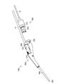
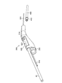
- FIG. 2 and 3 are perspective views of the handpiece 100.
- FIG. FIG. 2 shows a state where the actuator unit 300 is attached to the nozzle unit 200 (hereinafter referred to as “attached state”).
- FIG. 3 shows a state where the actuator unit 300 and the nozzle unit 200 are separated (hereinafter referred to as “separated state”).
- the actuator unit 300 is configured to be detachable from the nozzle unit 200.
- the actuator unit 300 is attached to the nozzle unit 200, and the actuator unit 300 and the nozzle unit 200 are integrated to function as the handpiece 100.
- the nozzle unit 200 is replaced every operation because the liquid flows inside. Further, among the components included in the liquid supply device 50, the ones in which the liquid flows (the water supply bag 51, the first to fourth water supply tubes 54a to 54d, the pump tube 55, etc.) are replaced every operation. Since the actuator unit 300 does not touch the liquid, it can be used in a plurality of operations by performing a sterilization process or a cleaning process.
- the nozzle unit 200 includes a handpiece case 210, a joint portion 250, and a suction force adjusting mechanism 500 in addition to the above-described injection tube 205 and suction tube 400.
- the handpiece case 210 has a function as a grip held by the user and a function of holding the flow path inside. This flow path is a flow path through which the liquid to be ejected and the liquid to be sucked flow as described above.
- the suction force adjusting mechanism 500 is provided in the handpiece 100 and includes a hole 522.
- the opening area of the hole 522 changes, the suction force by the suction pipe 400 changes (detailed with FIG. 5).
- the joint part 250 is a part for attaching / detaching the actuator unit 300 to / from the nozzle unit 200.
- the actuator unit 300 includes a connecting part 310 and a driving part 350.
- the connecting portion 310 mechanically and electrically connects the actuator cable 31 and the drive portion 350.
- the driving unit 350 generates a driving force for intermittently ejecting the liquid.
- FIG. 4 is a perspective view showing the nozzle unit 200.
- FIG. 4 shows a state in which the suction tube 400 is removed from the handpiece case 210.
- the handpiece 100 may be used with the suction tube 400 removed.
- suction using the suction tube 400 is not possible, but liquid can be ejected from the ejection tube 205.
- the suction tube 400 includes a convex portion 410.
- the convex part 410 is a part for attaching the suction tube 400 to the handpiece case 210.
- the fourth water supply tube 54 d is connected to the handpiece case 210. 2 and 3 do not show the fourth water supply tube 54d because of the line of sight.
- FIG. 5 is a cross-sectional view showing the handpiece 100.
- the fourth water supply tube 54d is bent in a U shape inside the handpiece case 210 and connected to the inlet channel 241.
- the inlet channel 241 communicates with the ejection pipe 205 via the liquid chamber 240 (see FIGS. 8 and 9).
- the channel diameter of the inlet channel 241 is smaller than the channel diameter of the injection pipe 205. For this reason, even if the pressure in the liquid chamber 240 fluctuates (described later), the liquid in the liquid chamber 240 is prevented from flowing back into the inlet channel 241.
- the handpiece case 210 has a recess 211 at the tip.
- the attachment of the suction pipe 400 is realized by fitting the convex portion 410 into the concave portion 211.
- the attached suction tube 400 communicates with the suction flow path section 230.
- the suction flow path unit 230 is connected to the suction tube 41 via the suction force adjustment mechanism 500.
- the user can adjust the suction force by the suction tube 400 using the hole 522. Specifically, if the area where the hole 522 is opened is reduced, the flow rate of air flowing in from the hole 522 is also reduced, so that the flow rate of fluid (air, liquid, etc.) sucked through the suction pipe 400 is reduced. growing. That is, the suction force by the suction pipe 400 is increased. On the contrary, if the area where the hole 522 is opened is increased, the flow rate of the air flowing from the hole 522 is also increased, so that the suction force by the suction pipe 400 is reduced. Usually, the user adjusts the open area of the hole 522 by adjusting the area where the hole 522 is closed by the thumb.
- the shape of the hole 522 is designed so that the suction force by the suction pipe 400 becomes minute or no suction force acts.
- the flow area of the suction pipe 400 is larger than the opening area of the hole 522
- the flow resistance of the suction pipe 400 is reduced by making the length of the suction pipe 400 longer than the length of the hole 522. It is larger than the flow path resistance. In this way, when the hole 522 is not covered at all, the suction force by the suction tube 400 can be made minute.
- the longitudinal direction is defined with respect to the handpiece case 210.
- the longitudinal direction is a direction included in the cross section shown in FIG. 5 and is a horizontal direction in a predetermined posture.
- the predetermined posture is a posture when the user holds the handpiece 100 with the hand after the palm is turned up.
- the longitudinal direction in the present embodiment matches the flow path direction of the suction flow path section 230.
- the flow path direction of the suction flow path section 230 is a flow direction in the suction flow path section 230 at a portion where the suction flow path section 230 is in contact with the suction force adjustment mechanism 500.
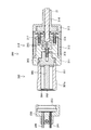
- FIG. 6 and 7 are enlarged sectional views showing the vicinity of the joint portion 250 and the actuator unit 300.
- FIG. FIG. 6 shows a mounted state.
- FIG. 7 shows a separated state.
- the driving unit 350 includes a housing 351, a fixed member 353, a piezoelectric element 360, and a movable plate 361.
- the housing 351 is a cylindrical member.
- the movable plate 361 includes a piston 362 and a drive side diaphragm 364.
- Piezoelectric element 360 is a laminated piezoelectric element.
- the piezoelectric element 360 is disposed in the housing 351 so that the extending and contracting direction is along the longitudinal direction of the housing 351.
- the piezoelectric element 360 in the present embodiment has a substantially regular quadrangular prism shape, is 3.5 mm square, and has a height of 18 mm.
- the fixing member 353 is fixed to one end of the housing 351.
- the piezoelectric element 360 is fixed to the fixing member 353 with an adhesive.
- the material of the drive side diaphragm 364 is a metal, specifically stainless steel, and more specifically SUS304 or SUS316L.
- the drive side diaphragm 364 is formed thicker (for example, 300 ⁇ m) in order to preload the piezoelectric element 360 (described later). Further, since the piezoelectric element 360 is made of metal and is formed thick, it is smoothly curved when pushed by the piston 362. For this reason, the liquid chamber side diaphragm 260 can also be smoothly deformed in the mounted state.
- the drive side diaphragm 364 is disposed so as to cover the other end of the housing 351 and is fixed to the housing 351 by welding.
- the piston 362 is fixed to one end of the piezoelectric element 360 with an adhesive and is disposed so as to contact the drive side diaphragm 364.
- the piston 362 has a shape in which cylinders having different diameters are stacked as concentric circles. The smaller diameter is in contact with the drive side diaphragm 364. For this reason, the drive side diaphragm 364 is not pushed toward the end, and a large force does not act on the welded portion.
- the piston 362 and the drive side diaphragm 364 are not fixed by an adhesive or the like but are only in contact with each other.
- a male screw portion 351a is provided on the outer periphery of the housing 351. The transition from the separated state to the mounted state is realized by tightening the male screw portion 351a to the female screw portion 253 provided in the joint portion 250.
- the connecting portion 310 includes a first case 311, a second case 312, a third case 313, a holding member 314, a metal plate 315, a first screw 316, a second screw 317, and a third screw 318. Is provided. Note that the metal plate 315 can also be referred to as the relay substrate 315.
- the first case 311 is fixed to the fixing member 353 by the first screw 316.
- the second case 312 is fixed to the first case 311 by a second screw 317 and a third screw 318.
- the two metal plates 315 are inserted (accommodated) in the first case 311.
- the holding member 314 is fixed by being crimped near the end of the actuator cable 31.
- the third case 313 is a member for connecting the second case 312 and the holding member 314.
- the third case 313 is fixed to the second case 312 in a state where the portion where the outer diameter of the holding member 314 is expanded is hooked.
- the actuator cable 31 is connected so as to be electrically connected to the two metal plates 315 while being fixed as described above.
- the metal plate 315 is connected to the positive electrode and the negative electrode of the piezoelectric element 360 by wiring (not shown).
- Piezoelectric element 360 expands and contracts in response to a drive signal input via actuator cable 31, metal plate 315, and the above wiring.
- the piston 362 vibrates in the longitudinal direction of the piezoelectric element 360.
- the drive side diaphragm 364 is deformed following the vibration.
- the piezoelectric element 360 is assembled in a preloaded state in order to appropriately perform expansion and contraction.
- the preloaded state is a state in which the piezoelectric element 360 is pressed toward the driving diaphragm 364 and the piezoelectric element 360 is compressed in the expansion / contraction direction.
- the preload load is 10 to 50% of the maximum generated force of the piezoelectric element 360, specifically 40 to 200N. For this reason, even when a drive signal is not input to the piezoelectric element 360, the drive side diaphragm 364 receives force from the piezoelectric element 360 via the piston 362. The reason that the drive side diaphragm 364 is made of metal and is thicker than the liquid chamber side diaphragm 260 is to hold the preload.
- the drive side diaphragm 364 is deformed as described above, the drive side diaphragm 364 can be deformed following the contraction of the piezoelectric element 360 even if it is not bonded to the piston 362.
- FIG. 8 and 9 are cross-sectional views showing the vicinity of the liquid chamber 240 in an enlarged manner.
- FIG. 8 shows a mounted state.
- FIG. 9 shows the separated state.
- a liquid chamber 240 is provided inside the joint portion 250.
- the liquid chamber 240 is formed by covering the recess 244 with the liquid chamber side diaphragm 260.
- the recess 244 is a portion that is thin and circularly recessed in the joint portion 250.
- the liquid chamber side diaphragm 260 is formed thinner than the driving side diaphragm 364 (for example, 50 to 100 ⁇ m) so as to be easily deformed in accordance with expansion and contraction of the piezoelectric element 360.
- the liquid chamber side diaphragm 260 has a diameter of 13 to 15 mm, and is fixed to the joint portion 250 by welding. The welding position is shown as welding Y1 shown in FIG.
- the material of the liquid chamber side diaphragm 260 is a metal, specifically stainless steel, and more specifically SUS304 or SUS316L.
- the liquid chamber side diaphragm 260 and the drive side diaphragm 364 are in contact with each other in the mounted state. For this reason, as described above, when the driving side diaphragm 364 is deformed, the liquid chamber side diaphragm 260 is similarly deformed.
- the volume of the liquid chamber 240 changes. Due to this variation, the pressure of the liquid filled in the liquid chamber 240 varies. When the pressure in the liquid chamber 240 decreases, the liquid flows into the liquid chamber 240 from the inlet channel 241. When the pressure in the liquid chamber 240 increases, the liquid flows out from the liquid chamber 240 to the ejection pipe 205. The liquid that has flowed out to the ejection tube 205 is ejected from the tip of the ejection tube 205. Since the pressure in the liquid chamber 240 rises intermittently, the liquid is ejected from the ejection pipe 205 intermittently.
- the liquid chamber side diaphragm 260 and the drive side diaphragm 364 are integrally deformed. That is, the liquid chamber side diaphragm 260 and the movable plate 361 are integrally deformed.
- Reference numeral 460 shown in FIG. 8 indicates a composite diaphragm 460 in which the liquid chamber side diaphragm 260 and the movable plate 361 that are integrally deformed in this manner are combined.
- the composite diaphragm 460 can be regarded as one diaphragm in the mounted state.
- FIG. 10 is a view for explaining the welding of the liquid chamber side diaphragm 260 and the driving side diaphragm 364.
- the housing 351 is provided with a chamfer 351b as shown in FIG.
- the chamfer 351b is provided so that the weld Y1 that fixes the liquid chamber side diaphragm 260 and the housing 351 do not interfere with each other.
- the front end of the housing 351 is retracted by a dimension C from the front end of the drive side diaphragm 364.
- a clearance is generated between the liquid chamber side diaphragm 260 and the housing 351 in the mounted state.
- symbol 255 shown by FIG. 10 shows the escape part 255 provided in another form. In this embodiment, as shown in FIG. 8, FIG. 9, etc., the escape part 255 is not provided.
- the relief portion 255 is a portion of the inner periphery of the joint portion 250 where the wall is sunk toward the inside. By providing the relief portion 255, the internal thread portion 253 can be easily processed.
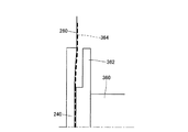
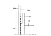
- FIG. 12, and FIG. 13 show a part of the cross section in the vicinity of the liquid chamber side diaphragm 260 and the drive side diaphragm 364.
- FIG. FIG. 11 shows the separated state.
- 12 and 13 show the mounted state.
- the drive side diaphragm 364 is indicated by a broken line in order to distinguish it from the liquid chamber side diaphragm 260.
- the liquid chamber side diaphragm 260 and the driving side diaphragm 364 are illustrated as flat shapes for the sake of simplicity.
- the actual liquid chamber side diaphragm 260 and the drive side diaphragm 364 are curved as shown in FIGS. 11, 12, and 13.
- FIGS. 11, 12, and 13 emphasize the bending state of the liquid chamber side diaphragm 260 and the driving side diaphragm 364.
- the driving side diaphragm 364 has a convex shape in the separated state.
- the convex shape is a shape bulging outward.
- the outer side of the driving side diaphragm 364 is the direction toward the opposite side to the piezoelectric element 360. That is, the direction is from the piezoelectric element 360 to the drive side diaphragm 364.
- the reason why the driving diaphragm 364 has a convex shape in the separated state is that the piezoelectric element 360 is assembled in a preloaded state as described above.
- the driving side diaphragm 364 has a smooth convex shape in the separated state. This is because the pressure due to the preload acting only on the contact portion with the piston 362 is dispersed around by the rigidity of the drive side diaphragm 364. The reason why the rigidity of the drive side diaphragm 364 is secured is that the drive side diaphragm 364 is made of metal and is formed thicker.
- the liquid chamber side diaphragm 260 has a convex shape in the separated state.
- the outside of the liquid chamber side diaphragm 260 is the direction toward the outside of the liquid chamber 240. That is, the direction is from the liquid chamber 240 to the liquid chamber-side diaphragm 260.
- the reason why the liquid chamber side diaphragm 260 has a convex shape is that the liquid chamber side diaphragm 260 has a convex shape.
- This molding is performed by press working utilizing the fact that the liquid chamber side diaphragm 260 is made of metal. This press work is performed before welding to the joint portion 250.
- FIG. 12 shows a state where the volume of the liquid chamber 240 is maximized in the mounted state (hereinafter referred to as “maximum state”). When no voltage is applied to the piezoelectric element 360, the volume of the liquid chamber 240 is maximized.
- FIG. 13 shows a state where the volume of the liquid chamber 240 is minimized (hereinafter referred to as “minimum state”) in the mounted state.
- the liquid chamber side diaphragm 260 and the drive side diaphragm 364 come into contact with each other.
- the drive side diaphragm 364 is supported by the piezoelectric element 360 and thus hardly deforms. Therefore, the drive side diaphragm 364 has substantially the same shape in the separated state (FIG. 11) and the maximum state (FIG. 12).
- the piezoelectric element 360 In the transition from the maximum state to the minimum state, the piezoelectric element 360 is displaced outward, so that the drive side diaphragm 364 has a convex shape even in the minimum state (FIG. 13).
- This convex shape is a smooth shape as in the maximum state.
- the smooth convex shape is obtained because the rigidity of the drive diaphragm 364 is ensured as described above.
- the liquid chamber side diaphragm 260 is deformed inward so as to follow the shape of the drive side diaphragm 364 in the above contact. As a result, the liquid chamber side diaphragm 260 has a concave shape on the outer side in the maximum state (FIG. 12). When the liquid chamber side diaphragm 260 reaches the minimum state (FIG. 13), it is further deformed inward. Since both concave shapes in the maximum state and the minimum state are shapes along the shape of the drive side diaphragm 364, they are smooth shapes.
- the liquid chamber side diaphragm 260 receives a force toward the inside in any state, so that a reaction force is always generated to try to expand outward in the mounted state. Moreover, this reaction force is generated as a large force because the liquid chamber side diaphragm 260 is originally convex. The large reaction force causes the liquid chamber side diaphragm 260 to deform following the deformation of the driving side diaphragm 364 when shifting from the minimum state to the maximum state, even if it is not bonded to the driving side diaphragm 364.
- Modification 1 will be described.
- a liquid chamber side diaphragm 260a is used instead of the liquid chamber side diaphragm 260 of the embodiment.
- FIG. 14 shows a part of a cross section in the vicinity of the liquid chamber side diaphragm 260a and the drive side diaphragm 364a in the separated state.
- the drive side diaphragm 364a has a convex shape in the separated state, like the drive side diaphragm 364 of the embodiment.
- the liquid chamber side diaphragm 260a has a substantially flat shape in the separated state.
- liquid chamber side diaphragm 260a is deformed inward so as to follow the shape of the drive side diaphragm 364a in the maximum state. Similarly to the embodiment, the liquid chamber side diaphragm 260a is further deformed inward in the minimum state than in the maximum state.
- the liquid chamber side diaphragm 260a since the liquid chamber side diaphragm 260a is flat, it is easy to manufacture the liquid chamber side diaphragm 260a. Further, the liquid chamber side diaphragm 260a does not turn over when the piezoelectric element 360 expands and contracts. “Turning over” means that the shape does not return to the original shape while largely deformed inside. When turning inside out, the force to bulge outward decreases. Therefore, the liquid chamber side diaphragm 260 turned upside down deteriorates the followability to the expansion and contraction of the piezoelectric element 360. In the embodiment described above, the expansion / contraction length of the piezoelectric element 360 is designed so that such a situation does not occur, and the followability of the liquid chamber side diaphragm 260 is ensured.
- the degree of freedom in design is improved, for example, by designing the extension / contraction length of the piezoelectric element 360 to be long.
- a reaction force is generated on the liquid chamber side diaphragm 260a to swell outward at all times in the mounted state, as in the embodiment. Therefore, similarly to the embodiment, even if the driving side diaphragm 364a is not bonded, the driving side diaphragm 364a is deformed following the deformation of the transition from the minimum state to the maximum state.
- the reaction force as described above can be generated because the drive side diaphragm 364a has a convex shape, and the liquid chamber side diaphragm 260 is deformed inward when shifting from the separated state to the mounted state.
- FIG. 15 shows a part of a cross section in the vicinity of the liquid chamber side diaphragm 260b and the drive side diaphragm 364b in the separated state.
- the liquid chamber side diaphragm 260b has a concave shape in the separated state, unlike the liquid chamber side diaphragm 260 of the embodiment.
- This concave shape is formed by press working.
- the driving diaphragm 364b has a convex shape in the separated state, like the driving diaphragm 364 of the embodiment.
- the drive-side diaphragm 364b has a larger protruding protrusion than the drive-side diaphragm 364 of the embodiment. This is because, in the maximum state, the concave liquid chamber side diaphragm 260b is deformed so as to follow the shape of the drive side diaphragm 364b.
- the liquid chamber side diaphragm 260b can be prevented from being turned over. Further, in the case of the liquid chamber side diaphragm 260b, even when combined with the drive side diaphragm 364b having a large protrusion in the separated state, the deformation does not become excessive. That is, the compatibility with the drive side diaphragm 364b formed by a large preload is good.
- the present invention is not limited to the embodiments, examples, and modifications of the present specification, and can be realized with various configurations without departing from the spirit of the present invention.
- the technical features in the embodiments, examples, and modifications corresponding to the technical features in the embodiments described in the summary section of the invention are to solve some or all of the above-described problems, or In order to achieve part or all of the effects described above, replacement or combination can be performed as appropriate. If the technical feature is not described as essential in this specification, it can be deleted as appropriate. For example, the following are exemplified.
- FIG. 16 is a table showing combinations of shapes of the drive side diaphragm and the liquid chamber side diaphragm. If two diaphragm shapes are classified into three, there are nine combinations. The three classifications are outwardly convex, flat, and outwardly concave.
- FIG. 16 is an outwardly convex combination, and corresponds to the combination shown in FIG. Similarly, FIG. 16B corresponds to the combination shown in FIG. 14, and FIG. 16C corresponds to the combination shown in FIG.
- the combinations (a), (b), (c), (d), and (g) may be an outwardly convex combination.
- the liquid chamber side diaphragm need not be made of metal.
- it may be made of a resin such as silicone.
- the drive side diaphragm may not be made of metal.
- it may be made of a resin such as silicone.
- the liquid chamber side diaphragm may have the same thickness as the driving side diaphragm or may be thicker than the driving side diaphragm.
- the piston may be cylindrical. That is, the piston may be formed as a cylinder having a single diameter.
- the piston may be omitted.
- the movable plate is constituted only by the driving side diaphragm.
- the nozzle unit and the actuator unit may be configured integrally. What is integrally configured as described above may be regarded as an actuator unit or a hand piece.
- the nozzle unit may be used multiple times by sterilization.
- the liquid to be ejected may be pure water or a chemical solution.
- the liquid ejecting apparatus may be used other than medical equipment.
- the liquid ejecting apparatus may be used in a cleaning apparatus that removes dirt with the ejected liquid, or may be used in a drawing apparatus that draws a line or the like with the ejected liquid.
- a configuration using a piezoelectric element as an actuator is adopted.
- a configuration in which liquid is ejected using an optical maser, or a configuration in which liquid is pressurized by a pump or the like may be employed.
- the structure in which the liquid is ejected using the optical maser is a structure in which bubbles are generated in the liquid by irradiating the liquid with the optical maser, and the liquid pressure rise caused by the generation of the bubbles is utilized.
- the configuration in which the liquid is intermittently ejected is employed, but a configuration having a function of ejecting the liquid continuously may be employed.
- the structure which can selectively use intermittent injection and continuous injection may be sufficient.
- only the tube pump may be driven with the driving of the actuator stopped or reduced.
- intermittent spraying may be performed for excision and continuous spraying may be performed for cleaning.
- the structure which can implement only continuous injection may be sufficient.
- the ablation may be performed by continuous injection.
- Drive part 350a ... Drive part, 351 ... Housing, 351a ... Male thread portion, 353 ... fixed member, 360 ... piezoelectric element, 361 ... movable plate, 362 ... piston, 364 ... drive side diaphragm, 370 ... adhesive containing hard material, 371 ... adhesive, 372 ... Hard material, 400 ... suction tube, 410 ... convex portion, 460 ... synthetic diaphragm, 500 ... suction force adjusting mechanism, 522 ... hole.
Landscapes
- Engineering & Computer Science (AREA)
- Health & Medical Sciences (AREA)
- Surgery (AREA)
- Life Sciences & Earth Sciences (AREA)
- Heart & Thoracic Surgery (AREA)
- Nuclear Medicine, Radiotherapy & Molecular Imaging (AREA)
- General Engineering & Computer Science (AREA)
- Biomedical Technology (AREA)
- Mechanical Engineering (AREA)
- Medical Informatics (AREA)
- Molecular Biology (AREA)
- Animal Behavior & Ethology (AREA)
- General Health & Medical Sciences (AREA)
- Public Health (AREA)
- Veterinary Medicine (AREA)
- Surgical Instruments (AREA)
Abstract
液体室を備えるノズルユニットと、圧電素子を備えるアクチュエーターユニットとが着脱可能な構成において、ノズルユニットが備える液体室側ダイヤフラムと、アクチュエーターユニットが備える駆動側ダイヤフラムとの関係を好適にすること。 液体噴射装置用ノズルユニットと液体噴射装置用アクチュエーターユニットとが分離した状態において、液体室側ダイヤフラムが液体室の外側に凸の形状をしていることと、駆動側ダイヤフラムが圧電素子と反対側に凸の形状をしていることとの少なくとも一方が満たされる。
Description
本発明は、液体の噴射に関する。
噴射管から液体を噴射するアプリケーター(ハンドピース)において、先端部(ノズルユニット)と本体部(アクチュエーターユニット)とを着脱可能にする構成が知られている(特許文献1)。本体部および先端部はそれぞれ、ダイヤフラムを備える。2つのダイヤフラムは、本体部および先端部が組み付けられた状態で互いに接触する。本体部のダイヤフラムは、圧電素子の伸縮に応じて変形する。先端部のダイヤフラムは、液体室の一部を区画する。この構成によって、先端部と本体部とを別体として構成しつつ、装着した状態では圧電素子の伸縮による液体室の容積変動を実現している。
上記先行技術の場合、2つのダイヤフラムの関係について詳細に検討されていない。本願発明は、上記先行技術を踏まえ、2つのダイヤフラムの関係を好適にすることを解決課題とする。
本発明は、上記課題を解決するためのものであり、以下の形態として実現できる。
(1)本発明の一形態によれば、圧電素子の伸縮に伴って変形する駆動側ダイヤフラムを備える液体噴射装置用アクチュエーターユニットに対して装着される液体噴射装置用ノズルユニットが提供される。この液体噴射装置用ノズルユニットは;前記液体噴射装置用アクチュエーターユニットに装着された場合に、前記駆動側ダイヤフラムと接触する液体室側ダイヤフラムと;前記液体室側ダイヤフラムによって一部が区画され、室内容積が変動可能な液体室と;前記液体室から液体を噴射するための噴射管とを備え;前記液体室側ダイヤフラムは、湾曲している。この形態によれば、液体室側ダイヤフラムの湾曲形状を利用して、種々の形状の駆動側ダイヤフラムと好適に接触させることができる。
(2)上記形態において、前記液体室側ダイヤフラムは、前記液体室の外側に凸の形状をしていてもよい。この形態によれば、液体噴射装置用アクチュエーターユニットに対して液体噴射装置用ノズルユニットが装着された状態(以下「装着状態」ともいう)において、液体室側ダイヤフラムが駆動側ダイヤフラムに対して押しつけられ易くなる。この結果、液体室側ダイヤフラムは、圧電素子の伸縮に伴って生じる変形において、圧電素子の収縮時の追従性が良好になり易い。
(3)上記形態において、前記液体室側ダイヤフラムは、前記液体室の外側に凹の形状をしていてもよい。この形態によれば、液体室側ダイヤフラムが、駆動側ダイヤフラムに押されて裏返ることが抑制される。液体室側ダイヤフラムは、液体室の外側に凹の形状をしているので、液体室の外側から押されても、裏返ることがない。
(4)上記形態において、前記駆動側ダイヤフラムは、前記圧電素子と反対側に凸の形状をしていてもよい。この形態によれば、液体室側ダイヤフラムを駆動側ダイヤフラムに対し、好適に接触させることができる。駆動側ダイヤフラムは、圧電素子と反対側に凸の形状をしているので、装着状態において、液体室側ダイヤフラムに対して押しつけられ易くなる。この結果、液体室側ダイヤフラムは、圧電素子の伸縮に伴って生じる変形において、圧電素子の収縮時の追従性が良好になり易い。
(5)上記形態において、前記液体室側ダイヤフラムは、金属製でもよい。この形態によれば、液体室側ダイヤフラムを所望の湾曲形状に加工し易くなる。
(6)上記形態において、前記液体室側ダイヤフラムは、前記駆動側ダイヤフラムよりも薄くてもよい。この形態によれば、液体室側ダイヤフラムが変形し易いので、圧電素子による伸縮によって、液体室の体積が効率良く変動する。
(7)他の形態として、液体室側ダイヤフラムによって一部が区画され、室内容積が変動可能な液体室と、前記液体室から液体を噴射するための噴射管とを備える液体噴射装置用ノズルユニットに対して装着される液体噴射装置用アクチュエーターユニットが提供される。この液体噴射装置用アクチュエーターユニットは;前記液体噴射装置用ノズルユニットに装着された場合に、前記液体室側ダイヤフラムと接触する駆動側ダイヤフラムと;前記駆動側ダイヤフラムを変形させる圧電素子とを備え;前記駆動側ダイヤフラムは、前記圧電素子と反対側に凸の形状をしている。この形態によれば、駆動側ダイヤフラムは、圧電素子と反対側に凸の形状をしているので、装着状態において、液体室側ダイヤフラムに対して押しつけられ易くなる。この結果、液体室側ダイヤフラムは、圧電素子の伸縮に伴って生じる変形において、圧電素子の収縮時の追従性が良好になり易い。
(8)上記形態において、前記液体室側ダイヤフラムは、湾曲していてもよい。この形態によれば、液体室側ダイヤフラムの湾曲形状を利用して、凸形状の駆動側ダイヤフラムと好適に接触させることができる。
(9)上記形態において、前記液体室側ダイヤフラムは、前記液体室の外側に凸の形状をしていてもよい。この形態によれば、液体室側ダイヤフラムは、液体室の外側に凸の形状をしているので、装着状態において、駆動側ダイヤフラムに対して押しつけられ易くなる。この結果、液体室側ダイヤフラムは、圧電素子の伸縮に伴って生じる変形において、圧電素子の収縮時の追従性が良好になり易い。
(10)上記形態において、前記液体室側ダイヤフラムは、前記液体室の外側に凹の形状をしていてもよい。この形態によれば、液体室側ダイヤフラムが、駆動側ダイヤフラムに押されて裏返ることが抑制される。液体室側ダイヤフラムは、液体室の外側に凹の形状をしているので、液体室の外側から駆動側ダイヤフラムによって押されても、裏返ることがない。
(11)上記形態において、前記駆動側ダイヤフラムは、金属製でもよい。この形態によれば、液体室側ダイヤフラムを、滑らかな形状に変形させることができる。駆動側ダイヤフラムが金属製なので、圧電素子の伸縮による駆動側ダイヤフラムの変形が、局所的に大きくならず、全体的にたわむように生じるからである。この結果、駆動側ダイヤフラムに押されて変形する液体室側ダイヤフラムは、滑らかな形状に変形する。
(12)上記形態において、前記駆動側ダイヤフラムは、前記液体室側ダイヤフラムよりも厚くてもよい。この形態によれば、液体室側ダイヤフラムを、滑らかに変形させることができる。駆動側ダイヤフラムが厚いので、圧電素子の伸縮による駆動側ダイヤフラムの変形が、局所的に大きくならず、全体的にたわむように生じるからである。この結果、駆動側ダイヤフラムに押されて変形する液体室側ダイヤフラムは、滑らかな形状に変形する。
(13)上記形態において、前記圧電素子は、プリロードされていてもよい。この形態によれば、圧電素子による伸縮が適切に実現される。
本発明は、上記以外の種々の形態で実現できる。例えば、上記の液体噴射装置用アクチュエーターユニット及び液体噴射装置用ノズルユニットを組み合わせた液体噴射装置用ハンドピースとして実現できる。さらに、液体噴射装置用ハンドピースと液体供給装置とを含む液体噴射装置として実現できる。
初めに、図1~図10を用いて、液体噴射装置20の概略を説明することで、液体の噴射機構および吸引機構について説明する。
図1は、液体噴射装置20の構成を概略的に示す。液体噴射装置20は、医療機関において利用される医療機器であり、患部に対して液体を噴射することによって、患部を切除する機能を有する。
液体噴射装置20は、制御部30と、アクチュエーター用ケーブル31と、ポンプ用ケーブル32、フットスイッチ35と、吸引装置40と、吸引チューブ41と、液体供給装置50と、ハンドピース100(操作部)とを備える。
液体供給装置50は、給水バッグ51と、スパイク針52と、第1~第5コネクター53a~53eと、第1~第4給水チューブ54a~54dと、ポンプチューブ55と、閉塞検出機構56と、フィルター57とを備える。ハンドピース100は、ノズルユニット200と、アクチュエーターユニット300とを備える。ノズルユニット200は、噴射管205と、吸引管400とを備える。
給水バッグ51は、透明な合成樹脂製であり、内部に液体(具体的には生理食塩水)が充填されている。なお、本願では、水以外の液体が充填されていても、給水バッグ51と呼ぶ。スパイク針52は、第1コネクター53aを介して、第1給水チューブ54aに接続されている。給水バッグ51にスパイク針52が刺されると、給水バッグ51に充填された液体が第1給水チューブ54aに供給可能な状態になる。
第1給水チューブ54aは、第2コネクター53bを介して、ポンプチューブ55に接続されている。ポンプチューブ55は、第3コネクター53cを介して、第2給水チューブ54bに接続されている。チューブポンプ60は、ポンプチューブ55を、ステーターとローターとで挟み込んでいる。チューブポンプ60は、内蔵するモーターの回転によって、複数のローラーを回転させることで、ポンプチューブ55を扱(しご)く。このように扱かれることによって、ポンプチューブ55内の液体は、第1給水チューブ54a側から、第2給水チューブ54b側に送り出される。
閉塞検出機構56は、第2給水チューブ54b内の圧力を測定することで、第1~第4給水チューブ54a~54d内の閉塞を検出する。
第2給水チューブ54bは、第4コネクター53dを介して、第3給水チューブ54cに接続されている。第3給水チューブ54cにはフィルター57が接続されている。フィルター57は、液体に含まれる異物を捕集する。
第3給水チューブ54cは、第5コネクター53eを介して、第4給水チューブ54dに接続されている。第4給水チューブ54dは、ハンドピース100に接続されている。第4給水チューブ54dを通じてハンドピース100に供給された液体は、アクチュエーターユニット300の駆動によって、噴射管205の先端に設けられたノズル207から間欠的に噴射される。このように液体が間欠的に噴射されることによって、少ない流量で切除能力が確保できる。
噴射管205及び吸引管400は、噴射管205を内管、吸引管400を外管とする二重管を構成する。吸引チューブ41は、ノズルユニット200に接続されている。吸引装置40は、吸引チューブ41を通じて、吸引管400内を吸引する。この吸引によって、吸引管400の先端付近の液体や切除片などが吸引される。
制御部30は、チューブポンプ60と、アクチュエーターユニット300とを制御する。具体的には、制御部30は、フットスイッチ35が踏まれている間、アクチュエーター用ケーブル31と、ポンプ用ケーブル32とを介して駆動信号を送信する。アクチュエーター用ケーブル31を介して送信された駆動信号は、アクチュエーターユニット300を駆動させる。ポンプ用ケーブル32を介して送信された駆動信号は、チューブポンプ60を駆動させる。よって、ユーザーがフットスイッチ35を踏んでいる間は液体が間欠的に噴射され、ユーザーがフットスイッチ35を踏んでいない間は液体の噴射が停止する。
図2及び図3は、ハンドピース100の斜視図である。図2は、アクチュエーターユニット300がノズルユニット200に装着された状態(以下「装着状態」という)を示す。図3は、アクチュエーターユニット300とノズルユニット200とが分離された状態(以下「分離状態」という)を示す。
アクチュエーターユニット300は、ノズルユニット200に対して着脱できるように構成されている。アクチュエーターユニット300がノズルユニット200に対して装着されて、アクチュエーターユニット300とノズルユニット200とが一体となることで、ハンドピース100として機能する。
ノズルユニット200は、内部に液体が流れるので、手術毎に交換される。さらに、液体供給装置50に含まれる構成要素のうち、内部に液体が流れるもの(給水バッグ51、第1~第4給水チューブ54a~54d、ポンプチューブ55等)は、手術毎に交換される。アクチュエーターユニット300は、液体に触れないので、滅菌処理や洗浄処理を施すことにより複数回の手術で使用できる。
ノズルユニット200は、先述した噴射管205と吸引管400とに加え、ハンドピースケース210と、ジョイント部250と、吸引力調整機構500とを備える。ハンドピースケース210は、ユーザーに把持されるグリップとしての機能と、流路を内部に保持する機能とを有する。この流路とは、先述したように、噴射される液体および吸引される液体が流れる流路のことである。
吸引力調整機構500は、ハンドピース100に設けられており、孔522を備える。孔522の開口面積が変化すると、吸引管400による吸引力が変化する(図5と共に詳述)。ジョイント部250は、ノズルユニット200に対してアクチュエーターユニット300を着脱するための部位である。
アクチュエーターユニット300は、連結部310と駆動部350とを備える。連結部310は、アクチュエーター用ケーブル31と駆動部350とを、機械的および電気的に連結している。駆動部350は、液体を間欠的に噴射するための駆動力を発生する。
図4は、ノズルユニット200を示す斜視図である。図4は、吸引管400がハンドピースケース210から取り外された状態を示す。ハンドピース100は、吸引管400が取り外された状態で使用されてもよい。吸引管400が取り外された状態では、吸引管400を用いた吸引はできないものの、噴射管205からの液体の噴射はできる。
吸引管400は、凸部410を備える。凸部410は、吸引管400をハンドピースケース210に装着するための部位である。
ハンドピースケース210には、図1と共に説明したように、第4給水チューブ54dが接続されている。なお、図2及び図3は、視線の関係で、第4給水チューブ54dを示していない。
図5は、ハンドピース100を示す断面図である。第4給水チューブ54dは、ハンドピースケース210内部でU字状に屈曲し、入口流路241に接続されている。入口流路241は、液体室240(図8、図9参照)を介して、噴射管205に通じている。
入口流路241の流路径は、噴射管205の流路径よりも小さい。このため、液体室240内の圧力が変動しても(後述)、液体室240内の液体が入口流路241に逆流することが抑制される。
ハンドピースケース210は、先端に凹部211を備える。吸引管400の装着は、凸部410が凹部211に嵌合することで実現される。装着された吸引管400は、吸引流路部230に通じている。吸引流路部230は、吸引力調整機構500を介して、吸引チューブ41に接続されている。
ユーザーは、孔522を利用して、吸引管400による吸引力の調整ができる。具体的には、孔522が開放されている面積を小さくすれば、孔522から流入する空気の流量も小さくなるので、吸引管400を介して吸引される流体(空気や液体等)の流量が大きくなる。つまり、吸引管400による吸引力が大きくなる。逆に、孔522が開放されている面積を大きくすれば、孔522から流入する空気の流量も大きくなるので、吸引管400による吸引力が小さくなる。通常、ユーザーは、孔522の開放面積の調整を、親指によって孔522を塞ぐ面積を調整することによって実現する。孔522が全く覆われていない状態では、吸引管400による吸引力が微小になるように、又は吸引力が全く作用しないように、孔522の形状が設計されている。本実施形態においては、吸引管400の流路面積が孔522の開口面積より大きいものの、吸引管400の長さを孔522の長さよりも長くすることで吸引管400の流路抵抗を孔522の流路抵抗よりも大きくしている。こうすることで孔522が全く覆われていない場合に、吸引管400による吸引力を微小とすることができる。
図5に示すように、ハンドピースケース210に対して長手方向が定義される。長手方向とは、図5に示した断面内に含まれる方向であって、所定の姿勢の際の水平方向である。所定の姿勢とは、ユーザーが手の平を上に向けてから、その手でハンドピース100を握った際の姿勢である。本実施形態における長手方向は、吸引流路部230の流路方向と一致する。吸引流路部230の流路方向とは、吸引流路部230が吸引力調整機構500と接触している部位における吸引流路部230内の流れの方向である。
図6及び図7は、ジョイント部250及びアクチュエーターユニット300付近を拡大して示す断面図である。図6は、装着状態を示す。図7は、分離状態を示す。
駆動部350は、ハウジング351と、固定部材353と、圧電素子360と、可動板361とを備える。ハウジング351は、円筒状の部材である。可動板361は、ピストン362と、駆動側ダイヤフラム364とを含む。
圧電素子360は、積層型圧電素子である。圧電素子360は、伸縮する方向がハウジング351の長手方向に沿うように、ハウジング351内に配置されている。本実施形態における圧電素子360は、ほぼ正四角柱形状であり、3.5mm四方で、高さが18mmである。
固定部材353は、ハウジング351の一端に固定されている。圧電素子360は、固定部材353に接着剤によって固定されている。
駆動側ダイヤフラム364の素材は、金属であり、具体的にはステンレス鋼であり、さらに具体的にはSUS304又はSUS316Lである。駆動側ダイヤフラム364は、圧電素子360のプリロード(後述)を実施するために厚めに形成される(例えば300μm)。また、圧電素子360が金属製で、且つ厚めに形成されているので、ピストン362に押された際に、滑らかに湾曲する。このため、装着状態において、液体室側ダイヤフラム260も滑らかに変形させることができる。
駆動側ダイヤフラム364は、ハウジング351の他端を覆うように配置され、ハウジング351に溶接によって固定されている。
ピストン362は、圧電素子360の一端に接着剤によって固定されていると共に、駆動側ダイヤフラム364に接触するように配置されている。ピストン362は、異なる径の円柱が、同心円として積層したような形状をしている。小さい径の方が、駆動側ダイヤフラム364と接触している。このため、駆動側ダイヤフラム364は、端の方が押されず、溶接箇所には大きな力が作用しないようになっている。ピストン362及び駆動側ダイヤフラム364は、接着剤等によって固定されてはおらず、接触しているのみである。
ハウジング351の外周には、雄ネジ部351aが設けられている。分離状態から装着状態への移行は、雄ネジ部351aを、ジョイント部250に設けられた雌ネジ部253に締め付けることで実現される。
連結部310は、第1ケース311と、第2ケース312と、第3ケース313と、保持部材314と、金属板315と、第1ネジ316と、第2ネジ317と、第3ネジ318とを備える。なお金属板315は中継基板315と言い換えることもできる。
第1ケース311は、第1ネジ316によって、固定部材353に固定されている。第2ケース312は、第2ネジ317と第3ネジ318とによって、第1ケース311に固定されている。2枚の金属板315は、第1ケース311内に挿入(収容)されている。
保持部材314は、アクチュエーター用ケーブル31の端部付近に加締められることによって固定されている。第3ケース313は、第2ケース312と保持部材314とを連結するための部材である。第3ケース313は、保持部材314の外径が膨らんだ部位を引っ掛けた状態で、第2ケース312に固定されている。
アクチュエーター用ケーブル31は、上記のように固定された状態で、2枚の金属板315と導通するように接続される。金属板315は、圧電素子360の正極、負極それぞれに、配線(図示しない)によって接続される。
圧電素子360は、アクチュエーター用ケーブル31、金属板315及び上記の配線を介して入力される駆動信号に応じて伸縮する。圧電素子360が伸縮すると、ピストン362が圧電素子360の長手方向に振動する。ピストン362が振動すると、駆動側ダイヤフラム364は、この振動に追従して変形する。
圧電素子360は、伸縮を適切に実施するために、プリロードされた状態で組み付けられている。プリロードされた状態とは、圧電素子360が駆動側ダイヤフラム364に向けて押しつけられ、圧電素子360が伸縮方向に圧縮された状態のことである。プリロードの荷重は、圧電素子360の最大発生力の10~50%であり、具体的には40~200Nである。このため、圧電素子360に駆動信号が入力されていない状態においても、駆動側ダイヤフラム364は、ピストン362を介して、圧電素子360から力を受ける。駆動側ダイヤフラム364が金属製で、液体室側ダイヤフラム260よりも厚く形成されているのは、プリロードを保持するためである。
上記のように駆動側ダイヤフラム364が変形しているため、駆動側ダイヤフラム364は、ピストン362と接着されていなくても、圧電素子360の収縮に追従して変形できる。
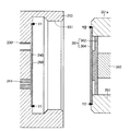
図8及び図9は、液体室240付近を拡大して示す断面図である。図8は、装着状態を示す。図9は、分離状態を示す。
ジョイント部250の内部には、液体室240が設けられている。液体室240は、窪み244に、液体室側ダイヤフラム260が覆い被さることで形成される。窪み244は、ジョイント部250において、薄く円形状に窪んだ部位である。液体室側ダイヤフラム260は、圧電素子360の伸縮に応じて変形しやすいように、駆動側ダイヤフラム364よりも薄く形成される(例えば50~100μm)。液体室側ダイヤフラム260は、直径が13~15mmであり、ジョイント部250に溶接によって固定されている。溶接位置は、図9に示される溶接Y1として示されている。液体室側ダイヤフラム260の素材は、金属であり、具体的にはステンレス鋼であり、さらに具体的にはSUS304又はSUS316Lである。
図8に示すように、液体室側ダイヤフラム260及び駆動側ダイヤフラム364は、装着状態において接触する。このため、先述したように駆動側ダイヤフラム364が変形すると、液体室側ダイヤフラム260も同様に変形する。
駆動側ダイヤフラム364が変形すると、液体室240の容積が変動する。この変動によって、液体室240内に満たされた液体の圧力が変動する。液体室240内の圧力が低下した際には、入口流路241から液体が液体室240に流入する。液体室240内の圧力が上昇した際には、液体が液体室240から噴射管205に流出する。噴射管205に流出した液体は、噴射管205の先端から噴射される。液体室240内の圧力が上昇するのは間欠的なので、噴射管205からの液体の噴射は間欠的に実施される。
上記のように、液体室側ダイヤフラム260及び駆動側ダイヤフラム364は、一体となって変形する。つまり、液体室側ダイヤフラム260及び可動板361は、一体となって変形する。図8に示された符号460は、このように一体となって変形する液体室側ダイヤフラム260と可動板361とを合わせた合成ダイヤフラム460を示す。合成ダイヤフラム460は、装着状態において、1つのダイヤフラムと捉えることができる。
図10は、液体室側ダイヤフラム260及び駆動側ダイヤフラム364の溶接について説明するための図である。ハウジング351には、図10に示すように面取り351bが設けられている。面取り351bは、液体室側ダイヤフラム260を固定する溶接Y1とハウジング351とが干渉しないように設けられている。
図10に示すように、ハウジング351の先端は、駆動側ダイヤフラム364の先端よりも寸法Cだけ引っ込んでいる。この結果、装着状態において、液体室側ダイヤフラム260とハウジング351との間にクリアランスが発生する。駆動側ダイヤフラム364を固定する溶接Y2の溶接痕が、このクリアランスに位置するように、溶接を実施することで、溶接Y2と液体室側ダイヤフラム260との干渉が回避されている。
図10に示された符号255は、他の形態において設けられる逃がし部255を示す。本実施形態では、図8,図9等に示すように、逃がし部255は設けられていない。逃がし部255は、ジョイント部250の内周において、壁が内部に向かってえぐれた部位である。逃がし部255を設けることによって、雌ネジ部253の加工が容易になる。
以下、液体室側ダイヤフラム260及び駆動側ダイヤフラム364の詳細の形状について説明する。
図11、図12、図13は、液体室側ダイヤフラム260及び駆動側ダイヤフラム364付近の断面の一部を示す。図11は、分離状態を示す。図12、図13は、装着状態を示す。図11、図12、図13は、液体室側ダイヤフラム260と区別するために、駆動側ダイヤフラム364を破線で示す。
なお、図5~図10においては、図示を簡単にするために、液体室側ダイヤフラム260及び駆動側ダイヤフラム364を、平らな形状として図示した。実際の液体室側ダイヤフラム260及び駆動側ダイヤフラム364は、図11、図12、図13に示すように、湾曲している。但し、図11、図12、図13は、液体室側ダイヤフラム260及び駆動側ダイヤフラム364の曲がり具合を強調して示している。
図11に示すように、駆動側ダイヤフラム364は、分離状態において凸形状をしている。凸形状とは、外側に膨らんだ形状をしていることである。駆動側ダイヤフラム364についての外側とは、圧電素子360と反対側への向きである。つまり、圧電素子360から駆動側ダイヤフラム364への向きである。駆動側ダイヤフラム364が分離状態において凸形状をしているのは、先述したように圧電素子360がプリロードされた状態で組み付けられているからである。
駆動側ダイヤフラム364は、分離状態において、滑らかな凸形状をしている。これは、ピストン362との接触部位のみに作用するプリロードによる圧力が、駆動側ダイヤフラム364の剛性によって周囲に分散するからである。駆動側ダイヤフラム364の剛性が確保されているのは、駆動側ダイヤフラム364が金属製であり、且つ、厚めに形成されているからである。
図11に示すように、液体室側ダイヤフラム260は、分離状態において凸形状をしている。液体室側ダイヤフラム260についての外側とは、液体室240の外側への向きである。つまり、液体室240から液体室側ダイヤフラム260への向きである。液体室側ダイヤフラム260が凸形状をしているのは、凸形状になるように成形されているからである。この成形は、液体室側ダイヤフラム260が金属製であることを利用し、プレス加工によって実施される。このプレス加工は、ジョイント部250への溶接前に実施される。
図12は、装着状態において、液体室240の容積が最大になった状態(以下「最大状態」という)を示す。圧電素子360に電圧が印加されていない場合、液体室240の容積は最大になる。図13は、装着状態において、液体室240の容積が最小になった状態(以下「最小状態」という)を示す。
分離状態から装着状態に移行する際、液体室側ダイヤフラム260及び駆動側ダイヤフラム364は接触する。この接触の際、駆動側ダイヤフラム364は、圧電素子360によって支持されているので殆ど変形しない。よって、駆動側ダイヤフラム364は、分離状態(図11)と最大状態(図12)とで、ほぼ同じ形状である。
最大状態から最小状態に移行する場合、圧電素子360は外側に向かって変位するので、駆動側ダイヤフラム364は最小状態(図13)においても凸形状をしている。この凸形状は、最大状態と同様に、滑らかな形状である。このように滑らかな凸形状になるのは、先述したように、駆動側ダイヤフラム364の剛性が確保されているためである。
液体室側ダイヤフラム260は、上記の接触の際、駆動側ダイヤフラム364の形状に沿うように、内側に変形する。この結果、液体室側ダイヤフラム260は、最大状態(図12)において、外側に凹形状になる。液体室側ダイヤフラム260は、最小状態(図13)になると、更に内側に変形する。最大状態と最小状態との何れの凹形状も、駆動側ダイヤフラム364の形状に沿う形状であるので、滑らかな形状である。
液体室側ダイヤフラム260は、上記のように、何れの状態においても内側への向きに力を受けるので、装着状態において常時、外側に向かって膨らもうとする反力が発生する。しかも、この反力は、液体室側ダイヤフラム260が元々は凸形状であるので、大きな力として発生する。この大きな反力によって、液体室側ダイヤフラム260は、駆動側ダイヤフラム364と接着されていなくても、最小状態から最大状態へ移行する際における駆動側ダイヤフラム364の変形に追従して変形する。
変形例1を説明する。変形例1は、実施形態の液体室側ダイヤフラム260の代わりに、液体室側ダイヤフラム260aが用いられる。図14は、分離状態における液体室側ダイヤフラム260a及び駆動側ダイヤフラム364a付近の断面の一部を示す。
図14に示すように、駆動側ダイヤフラム364aは、実施形態の駆動側ダイヤフラム364と同様に、分離状態において凸形状である。一方、液体室側ダイヤフラム260aは、実施形態の液体室側ダイヤフラム260とは異なり、分離状態において、ほぼ平らな形状をしている。
液体室側ダイヤフラム260aは、実施形態と同様に、最大状態において、駆動側ダイヤフラム364aの形状に沿うように、内側に変形する。液体室側ダイヤフラム260aは、実施形態と同様に、最小状態において、最大状態に比べて更に内側に変形する。
変形例1によれば、液体室側ダイヤフラム260aが平らであるので、液体室側ダイヤフラム260aの製造が容易になる。さらに、液体室側ダイヤフラム260aは、圧電素子360の伸縮に伴う裏返りが発生しない。裏返りとは、内側に大きく変形したまま、元の形状に戻らなくなることである。裏返りが発生すると、外側へ膨らもうとする力が小さくなる。よって、裏返った液体室側ダイヤフラム260は、圧電素子360の伸縮への追従性が悪化する。先述した実施形態では、このような事態が発生しないよう、圧電素子360の伸縮長さ等が設計され、液体室側ダイヤフラム260の追従性が確保されている。
一方、変形例1の液体室側ダイヤフラム260aは、元の形状が平らであるので、裏返りがそもそも発生しない。よって、圧電素子360の伸縮長さを長く設計する等、設計の自由度が向上する。
このように設計の自由度を向上させつつ、液体室側ダイヤフラム260aには、実施形態と同様に、装着状態において常時、外側に向かって膨らもうとする反力が発生する。よって、実施形態と同様に、駆動側ダイヤフラム364aと接着されていなくても、最小状態から最大状態へ移行する際における駆動側ダイヤフラム364aの変形に追従して変形する。上記のような反力を発生させることができるのは、駆動側ダイヤフラム364aが凸形状であり、分離状態から装着状態に移行する際に、液体室側ダイヤフラム260が内側に変形するからである。
変形例2を説明する。変形例2は、実施形態の液体室側ダイヤフラム260の代わりに、液体室側ダイヤフラム260bが用いられる。図15は、分離状態における液体室側ダイヤフラム260b及び駆動側ダイヤフラム364b付近の断面の一部を示す。
図15に示すように、液体室側ダイヤフラム260bは、実施形態の液体室側ダイヤフラム260とは異なり、分離状態において、凹形状をしている。この凹形状は、プレス加工によって成形されたものである。
駆動側ダイヤフラム364bは、実施形態の駆動側ダイヤフラム364と同様に、分離状態において凸形状である。但し、駆動側ダイヤフラム364bは、実施形態の駆動側ダイヤフラム364よりも、凸形状の突き出しが大きい。これは、最大状態において、凹形状をした液体室側ダイヤフラム260bを、駆動側ダイヤフラム364bの形状に沿うように変形させるためである。
変形例2によれば、変形例1と同様に、液体室側ダイヤフラム260bの裏返りを抑制できる。さらに、液体室側ダイヤフラム260bの場合、分離状態における突き出しが大きい駆動側ダイヤフラム364bと組み合わせても、変形が大きくなり過ぎない。つまり、大きなプリロードによって形成された駆動側ダイヤフラム364bとの相性が良い。
本発明は、本明細書の実施形態や実施例、変形例に限られるものではなく、その趣旨を逸脱しない範囲において種々の構成で実現できる。例えば、発明の概要の欄に記載した各形態中の技術的特徴に対応する実施形態、実施例、変形例中の技術的特徴は、先述の課題の一部又は全部を解決するために、或いは、先述の効果の一部又は全部を達成するために、適宜、差し替えや、組み合わせを行うことができる。その技術的特徴が本明細書中に必須なものとして説明されていなければ、適宜、削除できる。例えば、以下のものが例示される。
図16は、駆動側ダイヤフラムと液体室側ダイヤフラムとの形状の組み合わせを示すテーブルである。2つのダイヤフラムの形状を3つずつに分類すると、組み合わせは9つになる。3つの分類とは、外に凸、平ら、外に凹のことである。
図16の(a)は、両方とも外に凸の組み合わせであり、図11に示した組み合わせに相当する。同様に、図16の(b)は図14に示した組み合わせ、図16の(c)は図15に示した組み合わせに相当する。
図16に示した組み合わせのうち、両方とも平らの組み合わせ(e)以外の何れかであってもよい。或いは、少なくとも何れか一方が外に凸の組み合わせ(a),(b),(c),(d),(g)の何れかであってもよい。
液体室側ダイヤフラムは、金属製でなくてもよい。例えば、シリコーン等の樹脂製でもよい。
駆動側ダイヤフラムは、金属製でなくてもよい。例えば、シリコーン等の樹脂製でもよい。
液体室側ダイヤフラムは、駆動側ダイヤフラムと同じ厚さでもよいし、駆動側ダイヤフラムよりも厚くてもよい。
駆動側ダイヤフラムは、金属製でなくてもよい。例えば、シリコーン等の樹脂製でもよい。
液体室側ダイヤフラムは、駆動側ダイヤフラムと同じ厚さでもよいし、駆動側ダイヤフラムよりも厚くてもよい。
ピストンは、円柱形状でもよい。つまり、ピストンは、単一の径による円柱として形成されてもよい。
ピストンは、無くてもよい。この場合、駆動側ダイヤフラムのみで可動板が構成されることになる。
ピストンは、無くてもよい。この場合、駆動側ダイヤフラムのみで可動板が構成されることになる。
ノズルユニットとアクチュエーターユニットとが一体に構成されていてもよい。このように一体となって構成されたものを、アクチュエーターユニットと捉えてもよいし、ハンドピースと捉えてもよい。
ノズルユニットは、滅菌処理することで、複数回使用してもよい。
噴射する液体は、純水でもよいし薬液でもよい。
液体噴射装置は、医療機器以外に利用されてもよい。
例えば、液体噴射装置は、噴射した液体によって汚れを除去する洗浄装置に利用されてもよいし、噴射した液体によって線などを描く描画装置に利用されてもよい。
噴射する液体は、純水でもよいし薬液でもよい。
液体噴射装置は、医療機器以外に利用されてもよい。
例えば、液体噴射装置は、噴射した液体によって汚れを除去する洗浄装置に利用されてもよいし、噴射した液体によって線などを描く描画装置に利用されてもよい。
実施形態においてはアクチュエーターとして圧電素子を用いる構成を採用したが、光メーザーを用いて液体を噴射する構成や、ポンプ等により液体を加圧し、液体を噴射する構成を採用してもよい。光メーザーを用いて液体を噴射する構成とは、光メーザーを液体に照射して液体中に気泡を発生させ、この気泡の発生によって引き起こされる液体の圧力上昇を利用する構成である。
実施形態においては間欠的に液体を噴射する構成を採用したが、連続的に液体を噴射する機能を備えた構成を採用してもよい。例えば、間欠的な噴射と連続的な噴射とを使い分けることができる構成でもよい。実施形態のハードウエア構成を利用して連続的な噴射を実施するために、アクチュエーターの駆動を停止または低下させた状態でチューブポンプのみを駆動させてもよい。この構成の場合、間欠的な噴射を切除のために実施し、連続的な噴射を洗浄のために実施してもよい。
或いは、連続的な噴射のみが実施できる構成でもよい。この構成の場合、連続的な噴射によって切除を実施してもよい。
或いは、連続的な噴射のみが実施できる構成でもよい。この構成の場合、連続的な噴射によって切除を実施してもよい。
20…液体噴射装置、30…制御部、31…アクチュエーター用ケーブル、32…ポンプ用ケーブル、35…フットスイッチ、40…吸引装置、41…吸引チューブ、50…液体供給装置、51…給水バッグ、52…スパイク針、53a…第1コネクター、53b…第2コネクター、53c…第3コネクター、53d…第4コネクター、53e…第5コネクター、54a…第1給水チューブ、54b…第2給水チューブ、54c…第3給水チューブ、54d…第4給水チューブ、55…ポンプチューブ、56…閉塞検出機構、57…フィルター、60…チューブポンプ、100…ハンドピース、200…ノズルユニット、205…噴射管、207…ノズル、210…ハンドピースケース、211…凹部、230…吸引流路部、240…液体室、241…入口流路、244…窪み、250…ジョイント部、253…雌ネジ部、255…逃がし部、260…液体室側ダイヤフラム、300…アクチュエーターユニット、310…連結部、311…第1ケース、312…第2ケース、313…第3ケース、314…保持部材、315…金属板、316…第1ネジ、317…第2ネジ、318…第3ネジ、350…駆動部、350a…駆動部、351…ハウジング、351a…雄ネジ部、353…固定部材、360…圧電素子、361…可動板、362…ピストン、364…駆動側ダイヤフラム、370…硬質材入り接着剤、371…接着剤、372…硬質材、400…吸引管、410…凸部、460…合成ダイヤフラム、500…吸引力調整機構、522…孔。
Claims (14)
- 圧電素子の伸縮に伴って変形する駆動側ダイヤフラムを備える液体噴射装置用アクチュエーターユニットに対して装着される液体噴射装置用ノズルユニットであって、
前記液体噴射装置用アクチュエーターユニットに装着された場合に、前記駆動側ダイヤフラムと接触する液体室側ダイヤフラムと、
前記液体室側ダイヤフラムによって一部が区画され、室内容積が変動可能な液体室と、
前記液体室から液体を噴射するための噴射管とを備え、
前記液体室側ダイヤフラムは、湾曲している
液体噴射装置用ノズルユニット。 - 前記液体室側ダイヤフラムは、前記液体室の外側に凸の形状をしている
請求項1に記載の液体噴射装置用ノズルユニット。 - 前記液体室側ダイヤフラムは、前記液体室の外側に凹の形状をしている
請求項1に記載の液体噴射装置用ノズルユニット。 - 前記駆動側ダイヤフラムは、前記圧電素子と反対側に凸の形状をしている
請求項1から請求項3までの何れか一項に記載の液体噴射装置用ノズルユニット。 - 前記液体室側ダイヤフラムは、金属製である
請求項1から請求項4までの何れか一項に記載の液体噴射装置用ノズルユニット。 - 前記液体室側ダイヤフラムは、前記駆動側ダイヤフラムよりも薄い
請求項1から請求項5までの何れか一項に記載の液体噴射装置用ノズルユニット。 - 液体室側ダイヤフラムによって一部が区画され、室内容積が変動可能な液体室と、前記液体室から液体を噴射するための噴射管とを備える液体噴射装置用ノズルユニットに対して装着される液体噴射装置用アクチュエーターユニットであって、
前記液体噴射装置用ノズルユニットに装着された場合に、前記液体室側ダイヤフラムと接触する駆動側ダイヤフラムと、
前記駆動側ダイヤフラムを変形させる圧電素子とを備え、
前記駆動側ダイヤフラムは、前記圧電素子と反対側に凸の形状をしている
液体噴射装置用アクチュエーターユニット。 - 前記液体室側ダイヤフラムは、湾曲している
請求項7に記載の液体噴射装置用アクチュエーターユニット。 - 前記液体室側ダイヤフラムは、前記液体室の外側に凸の形状をしている
請求項8に記載の液体噴射装置用アクチュエーターユニット。 - 前記液体室側ダイヤフラムは、前記液体室の外側に凹の形状をしている
請求項8に記載の液体噴射装置用アクチュエーターユニット。 - 前記駆動側ダイヤフラムは、金属製である
請求項7から請求項10までの何れか一項に記載の液体噴射装置用アクチュエーターユニット。 - 前記駆動側ダイヤフラムは、前記液体室側ダイヤフラムよりも厚い
請求項7から請求項11までの何れか一項に記載の液体噴射装置用アクチュエーターユニット。 - 前記圧電素子は、プリロードされている
請求項7から請求項12までの何れか一項に記載の液体噴射装置用アクチュエーターユニット。 - 液体噴射装置用ノズルユニットと、前記液体噴射装置用ノズルユニットに装着可能な液体噴射装置用アクチュエーターユニットとを備える液体噴射装置用ハンドピースであって、
前記液体噴射装置用ノズルユニットは、
液体室側ダイヤフラムによって一部が区画され、室内容積が変動可能な液体室と、
前記液体室から液体を噴射するための噴射管とを備え、
前記液体噴射装置用アクチュエーターユニットは、
前記液体噴射装置用アクチュエーターユニットに装着された場合に、前記液体室側ダイヤフラムと接触する駆動側ダイヤフラムと、
前記駆動側ダイヤフラムを変形させる圧電素子とを備え、
前記液体噴射装置用ノズルユニットと前記液体噴射装置用アクチュエーターユニットとが分離した状態において、前記液体室側ダイヤフラムが前記液体室の外側に凸の形状をしていることと、前記駆動側ダイヤフラムが前記圧電素子と反対側に凸の形状をしていることとの少なくとも一方が満たされる
液体噴射装置用ハンドピース。
Applications Claiming Priority (2)
| Application Number | Priority Date | Filing Date | Title |
|---|---|---|---|
| JP2015059274A JP2016174867A (ja) | 2015-03-23 | 2015-03-23 | 液体噴射装置用ノズルユニット、液体噴射装置用アクチュエーターユニット、液体噴射装置用ハンドピース |
| JP2015-059274 | 2015-03-23 |
Publications (1)
| Publication Number | Publication Date |
|---|---|
| WO2016151998A1 true WO2016151998A1 (ja) | 2016-09-29 |
Family
ID=56978170
Family Applications (1)
| Application Number | Title | Priority Date | Filing Date |
|---|---|---|---|
| PCT/JP2016/000702 Ceased WO2016151998A1 (ja) | 2015-03-23 | 2016-02-10 | 液体噴射装置用ノズルユニット、液体噴射装置用アクチュエーターユニット、液体噴射装置用ハンドピース |
Country Status (2)
| Country | Link |
|---|---|
| JP (1) | JP2016174867A (ja) |
| WO (1) | WO2016151998A1 (ja) |
Citations (3)
| Publication number | Priority date | Publication date | Assignee | Title |
|---|---|---|---|---|
| JPH09300610A (ja) * | 1996-05-13 | 1997-11-25 | Citizen Watch Co Ltd | インクジェット記録ヘッド |
| WO2006080566A1 (en) * | 2005-01-26 | 2006-08-03 | Matsushita Electric Works, Ltd. | Piezoelectric-driven diaphragm pump |
| JP2010059902A (ja) * | 2008-09-05 | 2010-03-18 | Seiko Epson Corp | 圧電素子ユニット、ノズルユニット、流体噴射装置 |
-
2015
- 2015-03-23 JP JP2015059274A patent/JP2016174867A/ja active Pending
-
2016
- 2016-02-10 WO PCT/JP2016/000702 patent/WO2016151998A1/ja not_active Ceased
Patent Citations (3)
| Publication number | Priority date | Publication date | Assignee | Title |
|---|---|---|---|---|
| JPH09300610A (ja) * | 1996-05-13 | 1997-11-25 | Citizen Watch Co Ltd | インクジェット記録ヘッド |
| WO2006080566A1 (en) * | 2005-01-26 | 2006-08-03 | Matsushita Electric Works, Ltd. | Piezoelectric-driven diaphragm pump |
| JP2010059902A (ja) * | 2008-09-05 | 2010-03-18 | Seiko Epson Corp | 圧電素子ユニット、ノズルユニット、流体噴射装置 |
Also Published As
| Publication number | Publication date |
|---|---|
| JP2016174867A (ja) | 2016-10-06 |
Similar Documents
| Publication | Publication Date | Title |
|---|---|---|
| JP4311483B2 (ja) | 液体噴射装置およびそれを用いた手術器具 | |
| JP5959309B2 (ja) | 内視鏡管路切換装置 | |
| JP5585369B2 (ja) | 流体噴射装置、および医療機器 | |
| CN105125258A (zh) | 流体喷射装置和手术装置 | |
| JP6127642B2 (ja) | 液体噴射装置、および医療機器 | |
| WO2016151998A1 (ja) | 液体噴射装置用ノズルユニット、液体噴射装置用アクチュエーターユニット、液体噴射装置用ハンドピース | |
| JP2016176457A (ja) | 液体噴射装置用アクチュエーターユニット、液体噴射装置用ハンドピース | |
| JP5879904B2 (ja) | 流路管及び流体噴射装置 | |
| JP2016174892A (ja) | 液体供給装置、液体噴射装置 | |
| US9566796B2 (en) | Liquid supply device and liquid ejection device | |
| JP6009922B2 (ja) | 内視鏡用管路切換装置 | |
| WO2016147540A1 (ja) | 液体噴射装置用ノズルユニット | |
| JP2014188239A (ja) | 流体噴射装置、および、医療機器 | |
| CN107126247A (zh) | 手术用手持件、液体喷射装置、吸引装置 | |
| JP6589732B2 (ja) | 手術用ハンドピース、液体噴射装置 | |
| JP2016174729A (ja) | 医療用液体供給装置、医療用液体噴射装置 | |
| JP2017101598A (ja) | 液体噴射装置、プログラム、制御装置 | |
| JP2017153520A (ja) | 手術用ハンドピース、液体噴射装置、吸引装置 | |
| JP2017100082A (ja) | 液体噴射装置、プログラム、制御装置 | |
| JP2017136224A (ja) | 流体噴射装置 | |
| JP6003951B2 (ja) | 流体噴射部及び医療機器 | |
| WO2017150147A1 (ja) | 手術用ハンドピース、液体噴射装置、吸引装置 | |
| JP5304568B2 (ja) | 流体噴射装置、手術器具 | |
| JP2010084567A (ja) | 流体噴射装置、および手術用器具 | |
| JP2009108866A (ja) | 流体噴射装置 |
Legal Events
| Date | Code | Title | Description |
|---|---|---|---|
| 121 | Ep: the epo has been informed by wipo that ep was designated in this application |
Ref document number: 16767911 Country of ref document: EP Kind code of ref document: A1 |
|
| NENP | Non-entry into the national phase |
Ref country code: DE |
|
| 122 | Ep: pct application non-entry in european phase |
Ref document number: 16767911 Country of ref document: EP Kind code of ref document: A1 |