WO2016147697A1 - 内視鏡画像表示装置、内視鏡画像表示方法及び内視鏡画像表示プログラム - Google Patents
内視鏡画像表示装置、内視鏡画像表示方法及び内視鏡画像表示プログラム Download PDFInfo
- Publication number
- WO2016147697A1 WO2016147697A1 PCT/JP2016/051845 JP2016051845W WO2016147697A1 WO 2016147697 A1 WO2016147697 A1 WO 2016147697A1 JP 2016051845 W JP2016051845 W JP 2016051845W WO 2016147697 A1 WO2016147697 A1 WO 2016147697A1
- Authority
- WO
- WIPO (PCT)
- Prior art keywords
- image display
- display area
- image
- displayed
- button
- Prior art date
- Legal status (The legal status is an assumption and is not a legal conclusion. Google has not performed a legal analysis and makes no representation as to the accuracy of the status listed.)
- Ceased
Links
Images






Classifications
-
- A—HUMAN NECESSITIES
- A61—MEDICAL OR VETERINARY SCIENCE; HYGIENE
- A61B—DIAGNOSIS; SURGERY; IDENTIFICATION
- A61B1/00—Instruments for performing medical examinations of the interior of cavities or tubes of the body by visual or photographical inspection, e.g. endoscopes; Illuminating arrangements therefor
- A61B1/00002—Operational features of endoscopes
- A61B1/00004—Operational features of endoscopes characterised by electronic signal processing
- A61B1/00009—Operational features of endoscopes characterised by electronic signal processing of image signals during a use of endoscope
-
- G—PHYSICS
- G06—COMPUTING OR CALCULATING; COUNTING
- G06T—IMAGE DATA PROCESSING OR GENERATION, IN GENERAL
- G06T7/00—Image analysis
- G06T7/50—Depth or shape recovery
- G06T7/55—Depth or shape recovery from multiple images
- G06T7/593—Depth or shape recovery from multiple images from stereo images
-
- H—ELECTRICITY
- H04—ELECTRIC COMMUNICATION TECHNIQUE
- H04N—PICTORIAL COMMUNICATION, e.g. TELEVISION
- H04N13/00—Stereoscopic video systems; Multi-view video systems; Details thereof
- H04N13/20—Image signal generators
- H04N13/204—Image signal generators using stereoscopic image cameras
- H04N13/239—Image signal generators using stereoscopic image cameras using two two-dimensional [2D] image sensors having a relative position equal to or related to the interocular distance
-
- H—ELECTRICITY
- H04—ELECTRIC COMMUNICATION TECHNIQUE
- H04N—PICTORIAL COMMUNICATION, e.g. TELEVISION
- H04N21/00—Selective content distribution, e.g. interactive television or video on demand [VOD]
- H04N21/40—Client devices specifically adapted for the reception of or interaction with content, e.g. set-top-box [STB]; Operations thereof
- H04N21/41—Structure of client; Structure of client peripherals
- H04N21/422—Input-only peripherals, i.e. input devices connected to specially adapted client devices, e.g. global positioning system [GPS]
- H04N21/42204—User interfaces specially adapted for controlling a client device through a remote control device; Remote control devices therefor
-
- H—ELECTRICITY
- H04—ELECTRIC COMMUNICATION TECHNIQUE
- H04N—PICTORIAL COMMUNICATION, e.g. TELEVISION
- H04N21/00—Selective content distribution, e.g. interactive television or video on demand [VOD]
- H04N21/40—Client devices specifically adapted for the reception of or interaction with content, e.g. set-top-box [STB]; Operations thereof
- H04N21/43—Processing of content or additional data, e.g. demultiplexing additional data from a digital video stream; Elementary client operations, e.g. monitoring of home network or synchronising decoder's clock; Client middleware
- H04N21/431—Generation of visual interfaces for content selection or interaction; Content or additional data rendering
- H04N21/4312—Generation of visual interfaces for content selection or interaction; Content or additional data rendering involving specific graphical features, e.g. screen layout, special fonts or colors, blinking icons, highlights or animations
- H04N21/4316—Generation of visual interfaces for content selection or interaction; Content or additional data rendering involving specific graphical features, e.g. screen layout, special fonts or colors, blinking icons, highlights or animations for displaying supplemental content in a region of the screen, e.g. an advertisement in a separate window
-
- H—ELECTRICITY
- H04—ELECTRIC COMMUNICATION TECHNIQUE
- H04N—PICTORIAL COMMUNICATION, e.g. TELEVISION
- H04N21/00—Selective content distribution, e.g. interactive television or video on demand [VOD]
- H04N21/40—Client devices specifically adapted for the reception of or interaction with content, e.g. set-top-box [STB]; Operations thereof
- H04N21/47—End-user applications
-
- H—ELECTRICITY
- H04—ELECTRIC COMMUNICATION TECHNIQUE
- H04N—PICTORIAL COMMUNICATION, e.g. TELEVISION
- H04N23/00—Cameras or camera modules comprising electronic image sensors; Control thereof
- H04N23/50—Constructional details
- H04N23/555—Constructional details for picking-up images in sites, inaccessible due to their dimensions or hazardous conditions, e.g. endoscopes or borescopes
-
- G—PHYSICS
- G06—COMPUTING OR CALCULATING; COUNTING
- G06T—IMAGE DATA PROCESSING OR GENERATION, IN GENERAL
- G06T2200/00—Indexing scheme for image data processing or generation, in general
- G06T2200/24—Indexing scheme for image data processing or generation, in general involving graphical user interfaces [GUIs]
-
- G—PHYSICS
- G06—COMPUTING OR CALCULATING; COUNTING
- G06T—IMAGE DATA PROCESSING OR GENERATION, IN GENERAL
- G06T2207/00—Indexing scheme for image analysis or image enhancement
- G06T2207/10—Image acquisition modality
- G06T2207/10004—Still image; Photographic image
- G06T2207/10012—Stereo images
-
- G—PHYSICS
- G06—COMPUTING OR CALCULATING; COUNTING
- G06T—IMAGE DATA PROCESSING OR GENERATION, IN GENERAL
- G06T2207/00—Indexing scheme for image analysis or image enhancement
- G06T2207/10—Image acquisition modality
- G06T2207/10068—Endoscopic image
-
- H—ELECTRICITY
- H04—ELECTRIC COMMUNICATION TECHNIQUE
- H04N—PICTORIAL COMMUNICATION, e.g. TELEVISION
- H04N13/00—Stereoscopic video systems; Multi-view video systems; Details thereof
- H04N13/30—Image reproducers
-
- H—ELECTRICITY
- H04—ELECTRIC COMMUNICATION TECHNIQUE
- H04N—PICTORIAL COMMUNICATION, e.g. TELEVISION
- H04N21/00—Selective content distribution, e.g. interactive television or video on demand [VOD]
- H04N21/40—Client devices specifically adapted for the reception of or interaction with content, e.g. set-top-box [STB]; Operations thereof
- H04N21/41—Structure of client; Structure of client peripherals
- H04N21/422—Input-only peripherals, i.e. input devices connected to specially adapted client devices, e.g. global positioning system [GPS]
- H04N21/42204—User interfaces specially adapted for controlling a client device through a remote control device; Remote control devices therefor
- H04N21/42206—User interfaces specially adapted for controlling a client device through a remote control device; Remote control devices therefor characterized by hardware details
-
- H—ELECTRICITY
- H04—ELECTRIC COMMUNICATION TECHNIQUE
- H04N—PICTORIAL COMMUNICATION, e.g. TELEVISION
- H04N21/00—Selective content distribution, e.g. interactive television or video on demand [VOD]
- H04N21/40—Client devices specifically adapted for the reception of or interaction with content, e.g. set-top-box [STB]; Operations thereof
- H04N21/41—Structure of client; Structure of client peripherals
- H04N21/422—Input-only peripherals, i.e. input devices connected to specially adapted client devices, e.g. global positioning system [GPS]
- H04N21/42204—User interfaces specially adapted for controlling a client device through a remote control device; Remote control devices therefor
- H04N21/42206—User interfaces specially adapted for controlling a client device through a remote control device; Remote control devices therefor characterized by hardware details
- H04N21/4221—Dedicated function buttons, e.g. for the control of an EPG, subtitles, aspect ratio, picture-in-picture or teletext
-
- H—ELECTRICITY
- H04—ELECTRIC COMMUNICATION TECHNIQUE
- H04N—PICTORIAL COMMUNICATION, e.g. TELEVISION
- H04N21/00—Selective content distribution, e.g. interactive television or video on demand [VOD]
- H04N21/40—Client devices specifically adapted for the reception of or interaction with content, e.g. set-top-box [STB]; Operations thereof
- H04N21/41—Structure of client; Structure of client peripherals
- H04N21/422—Input-only peripherals, i.e. input devices connected to specially adapted client devices, e.g. global positioning system [GPS]
- H04N21/42204—User interfaces specially adapted for controlling a client device through a remote control device; Remote control devices therefor
- H04N21/42206—User interfaces specially adapted for controlling a client device through a remote control device; Remote control devices therefor characterized by hardware details
- H04N21/42224—Touch pad or touch panel provided on the remote control
Definitions
- the present invention relates to an endoscopic image display device, an endoscopic image display method, and an endoscopic image display program, and in particular, an endoscopic image display device that displays at least two endoscopic images, and an endoscopic image display.
- the present invention relates to a method and an endoscope image display program.
- endoscope apparatuses have been widely used in the industrial field and the medical field.
- an endoscope image of a subject obtained through an observation window provided at the distal end portion of the insertion portion is displayed on a monitor, and a user who is an examiner can inspect the subject while looking at the monitor. And can be recorded in a storage device.
- endoscope devices for example, an endoscope having a stereo measurement function.
- an endoscope apparatus having a stereo measurement function By using an endoscope apparatus having a stereo measurement function, it is possible to measure the distance from the distal end of the insertion portion to a designated point on the subject, or to measure the distance between two designated points on the subject.
- Japanese Unexamined Patent Application Publication No. 2006-226820 proposes a navigation device with a touch panel that can arbitrarily and freely change the scroll speed.
- a scroll speed designation icon as a speed mark is displayed on the screen, and the user touches the icon to give an instruction to change the scroll speed when scrolling the map to a desired speed. can do.
- endoscope devices are basically used for various examinations and various measurements, when specifying points on the subject displayed on the screen of the display device as measurement points, be careful with respect to operating devices such as joysticks. User operation is required.
- the change of the display range of the endoscopic image on the screen of the display device is realized by a zoom function or the like, but a joystick or the like is also used when the display range is changed accurately. Therefore, a complicated operation is required for the user.
- the display device with a touch panel described above can also be applied to an endoscope apparatus. Since a display device with a touch panel can easily select functions on the menu screen, the operability is good for the user.
- a mark such as a cursor is placed near the measurement point position.
- the present invention is capable of quickly specifying the position of a measurement point or the like in at least two or more endoscopic images or changing the display range of the endoscopic image displayed on the screen with a small number of operations.
- An object is to provide an endoscope image display device, an endoscope image display method, and an endoscope image display program.
- a display device having a first image display area and a second image display area for displaying an endoscopic image, the first image display area, and the second image
- a first operation instruction is received when the selection unit that selects any one of the display regions and the first image display region is selected by the selection unit, the first image display region and When the position of the mark displayed in the second image display area or the display range of the image is changed by a first change amount, and the second image display area is selected by the selection unit
- the second operation instruction is received, the position of the mark displayed in the first image display area and the second image display area or the display range of the image is different from the first change amount.
- a table that controls display so that it changes by the amount of change A control unit it is possible to provide an endoscope image display device having a.
- the first image display area and the second image display in a display device having a first image display area and a second image display area for displaying an endoscopic image.
- the first image display area and the second image display area are displayed.
- the first Display control is performed so that the position of the mark displayed in the image display area and the second image display area or the display range of the image is changed by a second change amount different from the first change amount.
- the first image display area and the second image display in a display device having a first image display area and a second image display area for displaying an endoscopic image.
- a program for displaying an area, the function for selecting one of the first image display area and the second image display area, and when the first image display area is selected In addition, when the first operation instruction is received, the position of the mark or the image display range displayed in the first image display area and the second image display area is changed in the first image display area.
- the second operation instruction is received when the second image display area is selected and the second image display area is selected, the second image display area and the first image display area and the second image display area are changed.
- the macro displayed in the second image display area An endoscope image display program for causing a computer to perform display control so as to change the position of the image or the display range of the image by a second change amount different from the first change amount. Can be provided.
- FIG. 1 is a block diagram showing a configuration of an endoscope apparatus according to a first embodiment of the present invention. It is a figure which shows the example of the stereo live image displayed on the display part 14 at the time of the stereo measurement mode concerning the 1st Embodiment of this invention. It is a figure which shows the other example of the stereo live image displayed on the display part 14 at the time of the stereo measurement mode concerning the 1st Embodiment of this invention. It is a figure which shows the other example of the stereo live image displayed on the display part 14 at the time of the stereo measurement mode concerning the 1st Embodiment of this invention.
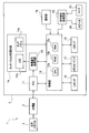
- FIG. 1 is a block diagram showing a configuration of an endoscope apparatus according to the present embodiment.
- the endoscope apparatus 1 includes an endoscope 2 and an apparatus main body 3 to which the endoscope 2 is connected.
- the endoscope 2 is configured to be detachable from the apparatus main body 3.
- the endoscope 2 outputs an imaging signal of a subject obtained through an observation window provided at the distal end portion of the insertion portion to the apparatus main body 3.
- the endoscope apparatus 1 has a stereo measurement function in addition to a normal observation function. Therefore, the endoscope 2 has an insertion portion (not shown), and an optical adapter 4 to be used when performing stereo measurement is detachable from the distal end portion of the insertion portion.
- the optical adapter 4 has two observation windows, and gives two optical images of a subject having parallax to the imaging surface of the imaging device of the insertion portion of the endoscope 2.
- the optical adapter 4 has a contact (not shown) for enabling the endoscope 2 or the apparatus main body 3 to detect that the optical adapter 4 is attached to the distal end of the insertion portion of the endoscope 2. ing.
- the apparatus body 3 includes a camera control unit (hereinafter referred to as CCU) 11, a control unit 12, a video signal processing circuit 13, a display unit with a touch panel (hereinafter referred to as display unit) 14, an operation unit 15, and a LAN interface.
- CCU camera control unit
- control unit 12 a control unit 12
- video signal processing circuit 13 a display unit with a touch panel
- display unit 14 an operation unit 15, and a LAN interface.
- LAN I / F 16
- memory card interface hereinafter abbreviated as memory card I / F
- USB I / F USB interface
- audio signal processing circuit 19 And a speaker 20 and a microphone 21.
- the CCU 11 drives an imaging device (not shown) of the endoscope 2 under the control of the control unit 12, receives an imaging signal output from the imaging device, and outputs it to the video signal processing circuit 13.
- the control unit 12 receives signals from various circuits in the apparatus body 3 and outputs control signals to the various circuits.
- the control unit 12 includes a central processing unit (hereinafter referred to as CPU) 12a, a ROM 12b, and a RAM 12c.
- the various setting data includes cursor change amounts da and db, which will be described later.
- the change amounts da and db are amounts corresponding to the unit movement distance of the finger F when touching the LCD 14a (that is, the touch panel) in a drag operation or the like described later. That is, each change amount da, db is defined as a function of the moving distance of the finger F on the LCD 14a. Each change amount da, db may be defined as a function of the moving speed of the finger F on the LCD 14a.
- the control unit 12 can determine whether or not the optical adapter 4 is attached to the distal end of the insertion portion of the endoscope 2 based on the conduction state signal of the contact of the optical adapter 4 through the endoscope 2. .
- the video signal processing circuit 13 processes the imaging signal from the CCU 11 to generate an image signal and outputs it to the display unit 14.
- the video signal processing circuit 13 executes image processing according to various functions under the control of the control unit 12. When the stereo measurement function is executed, the video signal processing circuit 13 generates two endoscopic images having parallax and outputs them to the display unit 14. That is, the endoscope apparatus 1 is an endoscope image display apparatus.
- the display unit 14 includes a liquid crystal display (LCD) 14a and a touch panel 14b.
- the touch panel 14b is, for example, an electrostatic touch panel, and is provided in close contact with the display screen of the liquid crystal display 14a.
- a position signal from the touch panel 14 b is output to the control unit 12.
- the operation unit 15 includes a plurality of operation devices such as a freeze button, a release button, a joystick, a zoom operation button, and a menu button.
- the LAN I / F 16 is an interface for connection to a local area network (hereinafter referred to as LAN).
- the endoscope apparatus 1 can communicate with an external device connected to the LAN via the LAN I / F 16.
- the memory card I / F 17 is an interface for mounting a memory card as a storage medium.
- the endoscope apparatus 1 can record an endoscope image to a memory card and read data from the memory card via the memory card I / F 17.
- the USB I / F 18 is an interface for connecting a USB (Universal Serial Bus) cable or a USB device.
- the endoscope apparatus 1 can record an endoscopic image on a USB device and read data from the USB device via the USB I / F 18.
- the audio signal processing circuit 19 processes the audio signal from the control unit 12 under the control of the control unit 12, outputs audio from the speaker 20, and processes the audio signal from the microphone 21 to the control unit 12. Output.
- the endoscope apparatus 1 can record and reproduce audio along with the endoscopic image.
- a user who is an inspector can execute various functions of the endoscope apparatus 1 by operating the touch panel 14b or the operation unit 15.
- the control unit 12 reads a predetermined program from the ROM 12b in accordance with a command instructed on the touch panel 14b or the operation unit 15, and displays the endoscopic image on the LCD 14a by executing the program while using the RAM 12c as a work area. Or the obtained endoscopic image can be recorded on a memory card.
- the user attaches the optical adapter 4 to the distal end portion of the insertion portion of the endoscope 2, selects a desired command from the menu screen displayed on the screen of the LCD 14a, and instructs execution thereof. It is also possible to cause the mirror device 1 to execute a stereo measurement function.
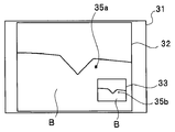
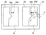
- FIG. 2A to 2C are diagrams illustrating examples of stereo live images displayed on the display unit 14 in the stereo measurement mode.
- a screen 31 in FIG. 2A is a graphical user interface (GUI) including two image display areas 32 and 33 on which a stereo live image is displayed.
- the screen 31 displayed on the LCD 14a has two image display areas for displaying two images of a left eye image and a right eye image. Therefore, the display unit 14 is a display device having a left image display area 32 and a right image display area 33 for displaying an endoscopic image.
- GUI graphical user interface
- the left image display area 32 displays a left eye image
- the right image display area 33 displays a right eye image.
- the endoscope 2 generates an imaging signal including left and right images by the optical adapter 4, and the apparatus body 3 generates a left eye image and a right eye image from the received imaging signal and displays them on the LCD 14a.
- the left image display area 32 and the right image display area 33 are displayed on one display unit of the LCD 14a of the display unit 14, but the left image display area 32 and the right image are displayed using two display devices.
- the display area 33 may be displayed on a separate display device.
- the left image display area 32 and the right image display area 33 need not have the same size.
- the left image display area 32 may be displayed larger on the screen 31, and the right image display area 33 may be displayed smaller as a confirmation image.
- the left image display area 32 and the right image display area 33 are rotated by 90 degrees, the left image display area 32 is enlarged to fit the screen 31, and the right image display area 33 is expanded. May be displayed on the left image display area 32 as a confirmation image.
- the user can specify measurement points in the stereo measurement mode. For example, a cursor as a mark for designating a measurement point is displayed on the screen, and the cursor is moved to a desired position by dragging with a finger on the touch panel 14b to designate the measurement point. it can.
- the user can move either the left eye image cursor 35 a displayed in the left image display area 32 or the right eye image cursor 35 b displayed in the right image display area 33.
- the cursor is moved by a drag operation in which the cursor to be moved on the left image display area 32 or the right image display area 33 is moved in a moving direction while being touched by the user after long pressing with a finger.
- the cursor is moved by, for example, specifying the cursor to be moved by double-tapping on the screen and then performing a swipe operation on the screen (that is, touching the screen with a finger without specifying the touched location)
- the operation may be performed by an operation such as an operation of moving the user in the direction in which the user wants to move) or a flick operation (an operation of moving quickly to play a short distance).
- cursors 35a and 35b which are marks for designating measurement points, are displayed in image display areas 32 and 33, respectively.
- a part of the blade B in the jet engine is displayed on the LCD 14a.
- the endoscopic image displayed in the left image display area 32 and the endoscopic image displayed in the right image display area 33 are left and right endoscopic images for stereo measurement, and are images having parallax with each other. .
- the position of the cursor 35a and the position of the cursor 35b are displayed at positions corresponding to the parallax between the two endoscopic images. Therefore, when the position of the cursor 35a in the left image display area 32 is moved, the position of the cursor 35b in the right image display area 33 is also moved, but the position of the cursor 35b is at the position on the subject indicated by the cursor 35a. The corresponding position on the right eye image is the position calculated by the matching process. Similarly, when the position of the cursor 35b in the right image display area 33 is moved, the position of the cursor 35a in the left image display area 32 is also moved, but the position of the cursor 35a is a position on the subject indicated by the cursor 35b. The position on the left eye image corresponding to is the position calculated by the matching process.
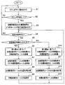
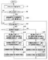
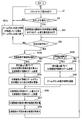
- FIG. 3 is a flowchart showing an example of the flow of cursor display processing in the stereo measurement mode.
- the processing of FIG. 3 is performed by the CPU 12a of the control unit 12 reading out and executing a cursor display processing program from the ROM 12b when the stereo measurement optical adapter 4 is attached to the distal end of the insertion unit.
- the control unit 12 outputs an instruction to the video signal processing circuit 13 to display a stereo live image as shown in FIGS. 2A to 2C on the LCD 14a (S1).
- control unit 12 determines whether or not the stereo measurement mode is set (S2).
- the setting of the stereo measurement mode is performed when the user selects the stereo measurement mode from the menu screen.
- the process returns to S1.
- the control unit 12 reads from the ROM 12b information on the change amount da of the cursor 35a for the left eye image and the change amount db of the cursor 35b for the right eye image.
- the control unit 12 determines whether or not a predetermined operation has been performed on the touch panel 14b (S4). If there is no predetermined operation on the touch panel 14b, the process returns to S1.
- the predetermined operation is a drag operation for moving the finger F after a long press. That is, it is determined whether a drag operation for moving the left eye image cursor 35a or the right eye image cursor 35b on the touch panel 14b while touching the finger F is performed.
- the control unit 12 determines whether the operation is performed on the left image display area 32 (S5).
- the processes of S4 and S5 constitute a selection unit that selects one of the left image display area 32 and the right image display area 33. That is, one of the left image display area 32 and the right image display area 33 is selected by touching the cursor 35a or 35b.
- selection of one of the left image display area 32 and the right image display area 33 may be performed by touching the selected image display area or by selecting on the menu screen. In that case, since either one of the left image display area 32 and the right image display area 33 is selected according to the touch on the image display area to be selected or the selection result on the menu screen, the image display area to be selected is selected.
- the touch detection process and the selection instruction input process using the menu screen and its joystick constitute a selection unit.
- the control unit 12 moves the cursor 35a (that is, the distance that the cursor 35a has moved by the drag operation on the display unit 14). Therefore, the cursor 35a for the left eye image is moved in the left image display area 32 based on the change amount da (S6).
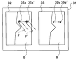
- FIG. 4 is a diagram showing a state where the user's finger F is touching the cursor 35a for the left eye image.
- the user performs a drag operation to move the cursor 35a for the left eye image in a direction in which the user wants to move from a state where the finger F is touching the touch panel 14b. Since the change in the position of the finger F in the drag operation is input to the control unit 12, the control unit 12 can calculate the amount of movement of the finger F in the drag operation.
- the control unit 12 moves the cursor 35a for the left eye image in the drag direction (direction indicated by the dotted line) in the left image display area 32 by an amount determined from the movement distance of the finger F based on the change amount da. Move with.
- the change amount da is set to 1 cm on the LCD 14a and the finger F is moved 1 cm on the LCD 14a
- the finger F is moved 1 cm on the LCD 14a
- the cursor 35a for the left eye image is Move 1 cm in the drag direction on the LCD 14a.
- the moved cursor 35a is defined as a cursor 35a '.
- the control unit 12 moves the right eye image cursor 35b within the right image display area 33 by a distance corresponding to the amount of movement of the left eye image cursor 35a (S7).
- the right eye image cursor 35b also moves in the right image display area 33 in the drag direction. Move 1 cm
- the moved cursor 35b is set as a cursor 35b '.
- the control unit 12 moves the right-eye image cursor 35b in the right-image display area 33, and then the right-image display area corresponding to the position of the left-eye image cursor 35a in the left-image display area 32.
- the position of the cursor 35b for the right eye image in 33 is recalculated by matching processing (S8).
- the recalculation of the position of the right eye image cursor 35b is performed after the right eye image cursor 35b is moved in the right image display area 33 (S7).
- the right eye image cursor 35b may be moved in the right image display area 33 while correcting the position of the right eye image cursor 35b by recalculation.
- control unit 12 redisplays the cursor 35b for the right eye image at the corrected position in the recalculated right image display area 33 (S9). After S9, the process returns to S4.
- the control unit 12 moves the movement amount of the cursor 35b for the right eye image (that is, the cursor 35b is dragged on the display unit 14).
- the cursor 35b for the right eye image is moved within the right image display area 33 based on the change amount db (S10).
- FIG. 5 is a diagram illustrating a state where the user's finger F is touching the cursor 35b for the right eye image. The user performs a drag operation to move the right eye image cursor 35b in a direction in which the finger F is in contact with the touch panel 14b.
- the control unit 12 moves the cursor 35b for the right eye image in the drag direction (direction indicated by the dotted line) in the right image display area 33 by an amount determined from the movement distance of the finger F based on the change amount db. Move with.
- the change amount db is set to 0.1 cm on the LCD 14a and the finger F is moved 1 cm on the LCD 14a
- the cursor 35b for the right eye image Moves 0.1 cm in the drag direction on the LCD 14a.
- the moved cursor 35b is set as a cursor 35b '.
- the position of the finger F ′ after movement is different from the position of the cursor 35b ′ after movement.
- the control unit 12 moves the left-eye image cursor 35a within the left-image display area 32 by a distance corresponding to the movement amount of the right-eye image cursor 35b (S11).
- the left eye image cursor 35a also moves in the left image display area 32 in the drag direction. Move 0.1 cm.
- the moved cursor 35a is defined as a cursor 35a '.
- control unit 12 moves the left image display area corresponding to the position of the right eye image cursor 35b in the right image display area 33.
- the position of the cursor 35a for the left eye image within 32 is recalculated by matching processing (S12).
- the recalculation of the position of the cursor 35a for the left eye image is performed after moving the cursor 35a for the left eye image within the left image display area 32 (S11), but in S11, The left eye image cursor 35a may be moved in the left image display region 32 while correcting the position of the left eye image cursor 35a by recalculation.
- the control unit 12 redisplays the cursor 35a for the left eye image at the corrected position in the recalculated left image display area 32 (S13). After S13, the process returns to S4.
- the processing in FIG. 3 ends when the user instructs the end of the stereo measurement processing mode on the menu screen.
- the process is displayed in the left image display area 32 and the right image display area 33.
- the position of each of the cursors 35a and 35b as the mark being changed is changed by the change amount da and the right image display area 33 is selected, if a predetermined operation instruction is received by a drag operation, the left image display area 32 and A display control unit is configured to perform display control so that the positions of the cursors 35a and 35b as marks displayed in the right image display area 33 are changed by a change amount db different from the change amount da.
- the process of FIG. 3 is repeated so that the user moves the cursors 35a and 35b by touching the left image display area 32.
- the coarse movement for large movement and the fine movement for small movement of the cursors 35a and 35b so as to touch the inside of the right image display area 33 can be repeated one or more times. Therefore, the user can quickly and accurately move the cursors 35a and 35b to desired positions.
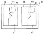
- FIG. 6 is a diagram for explaining the movement of the cursor. If the user wants to move the cursors 35a and 35b to the desired position P1, the user performs the above-described rough movement and fine movement several times by the above-described drag operation, thereby moving the cursors 35a and 35b to the desired position.
- the position P1 can be easily and quickly moved with a small number of operations.
- FIG. 7 is a diagram for explaining another example of the movement of the cursor.
- FIG. 7 shows a case where the cursor is moved in a desired direction while touching an arbitrary position on the screen.
- the cursors 35a and 35b move in the direction of the finger.
- the cursor 35 a moves in the direction of the finger F.
- the cursor 35a moves to the position of the finger F, it stops.
- the cursor 35a moves toward the destination where the finger F has moved. If the finger 35 is released while the cursor 35a is moving toward the finger F, the cursor 35a stops.
- the cursor 35b moves and stops in accordance with the movement and stop of the cursor 35a.
- the cursors 35a and 35b move coarsely
- the cursors 35a and 35b move finely.
- the change amount da for the left image display area 32 touched by the finger F or the right image display area first is kept away from the touch panel 14b and the drag operation is continuously performed.
- the change amount db for 33 the cursors 35a and 35b are moved even if the image display area first touched by the finger F is exceeded. That is, when the operation is performed beyond the image display area touched by the finger F first, the value of the amount of change for the image display area first touched by the finger F is continuously used to change the cursors 35a and 35b. Move.
- the cursor 35a continues.
- the position of the cursor is continuously changed.
- the position of 35b may be changed based on the change amount db.
- an endoscopic image display device that can quickly specify the position of a measurement point or the like in at least two or more endoscopic images with a small number of operations is provided. be able to.
- the cursor is moved on one of the two image display areas on the display unit 14, the other of the at least two image display areas is not hidden by the finger F or the hand.
- the position of the cursor on the display area can be reliably recognized.
- the cursor is operated by touching an arbitrary position on the screen as shown in FIG. 7, the positions of the cursors on the two image display areas can be recognized.
- the present embodiment relates to an operation for enlarging and reducing an endoscopic image.
- the user may want to see the endoscopic image in an enlarged manner, or may want to view it in a reduced size.
- the present embodiment relates to an endoscope apparatus that can quickly perform such an operation of changing the display range of an endoscopic image with a small number of operations.
- the endoscope apparatus according to the present embodiment has the same configuration as the endoscope apparatus 1 according to the first embodiment, hereinafter, the same reference numerals are used for the same configurations, and descriptions thereof are omitted, and different configurations are used. explain.
- FIG. 8 is a diagram showing operations for enlarging and reducing an endoscopic image in a stereo live image.
- the user performs a pinch-in or pinch-out operation with the two fingers F1 and F2 on the display unit 14, thereby zooming out or zooming in the endoscopic images displayed in the left image display area 32 and the right image display area 33. It can be performed.
- FIG. 8 shows a pinch-in or pinch-out operation performed by two fingers F1 and F2 in the right image display area 33.
- a dotted line PO indicates a pinch-out operation that increases the distance between the two fingers F1 and F2
- a dotted line PI indicates a pinch-in operation that decreases the distance between the two fingers F1 and F2. Yes.
- the endoscope image is enlarged or zoomed in by the pinch-out operation, and the endoscope image is reduced or zoomed out by the pinch-in operation.
- a pinch-in or pinch-out operation can be performed on the right image display area 33, and a pinch-in or pinch-out operation can also be performed on the left image display area 32.
- the zoom amount is large in the pinch-in or pinch-out operation on the left image display region 32, and the zoom amount is small in the pinch-in or pinch-out operation on the right image display region 33.
- the change amount dc is a change amount during zooming in the left image display region 32
- the change amount dd is a change amount during zooming in the right image display region 33.
- the change amounts dc and dd are amounts corresponding to changes in the distance between the fingers F1 and F2 when the LCD 14a (ie, the touch panel) is touched in a pinch-in or pinch-out operation. That is, each change amount dc, dd is defined as a change amount function of the distance between the fingers F1 and F2 on the LCD 14a.
- each change amount dc, dd is defined so as to enlarge 1.1 times.
- the change amounts dc and dd are used, but the change rate may be used.
- the rate of change is indicated by L1 / L0.
- FIG. 9 is a flowchart illustrating an example of the flow of zoom display processing in the stereo measurement mode.
- the same processes as those in FIG. 9 the same processes as those in FIG.
- the control unit 12 receives information about the change amount dc that is the zoom change amount for the left eye image and the change amount dd that is the zoom change amount for the right eye image from the ROM 12b. Read (S21).
- the control unit 12 determines whether or not a predetermined operation has been performed on the touch panel 14b (S22). If there is no predetermined operation on the touch panel 14b, the process returns to S1.
- the predetermined operation is the above-described pinch-in or pinch-out operation. That is, it is determined whether a pinch-in or pinch-out operation has been performed in the left image display area 32 or the right image display area 33.
- the control unit 12 determines whether the operation is a zoom operation by a pinch-in or pinch-out operation in the left image display area 32 (S23). .
- the control unit 12 uses the two fingers F1 in the left image display area 32 based on the change amount dc.
- the zoom processing of the left image display area 32 is performed from the amount of change in the distance between F2 (S24). During the pinch-in operation, the left image display area 32 is reduced. When the pinch-out operation is performed, the left image display area 32 is enlarged.
- control unit 12 zooms the right image display area 33 by the zoom amount of the left image display area 32 (S25). As a result, the right image display area 33 is also zoomed by the same amount as the left image display area 32.
- the control unit 12 zooms the right image display area 33 and then recalculates the display range of the right image display area 33 corresponding to the display range of the left image display area 32 by matching processing (S26).
- control unit 12 redisplays the display range of the right image display area 33 corrected by recalculation (S27). After S27, the process returns to S22.
- the control unit 12 uses the two fingers F1 in the right image display area 33 based on the change amount dd.
- the right image display area 33 is zoomed from the amount of change in the distance between F2 (S28).
- the pinch-in operation the reduction operation of the right image display region 33 is performed, and during the pinch-out operation, the enlargement operation of the right image display region 33 is performed.
- the control unit 12 zooms the left image display area 32 by the zoom amount of the right image display area 33 (S29). As a result, the left image display area 32 is also zoomed by the same amount as the right image display area 33. After zooming the left image display region 32, the control unit 12 recalculates the display range of the left image display region 32 corresponding to the display range of the right image display region 33 by matching processing (S30).
- control unit 12 redisplays the display range of the left image display area 32 corrected by recalculation (S31). After S31, the process returns to S22.
- the recalculation of the display range in S26 and S30 is performed after zooming the corresponding other image display area (S25, S29).
- the corresponding other image display area is displayed. While recalculating the display range, the other corresponding image display area may be zoomed.
- the processing in FIG. 9 ends when the user instructs the end of the stereo measurement processing mode on the menu screen.
- the processing from S24 to S31 receives an operation instruction for a zoom operation such as a pinch-in or pinch-out operation while the left image display area 32 is selected, the left image display area 32 and the right image display are displayed.
- the display range of the area 33 is changed by the change amount dc and the operation instruction for the zoom operation is received when the right image display area 33 is selected, the display ranges of the left image display area 32 and the right image display area 33 are changed.
- a display control unit is configured to perform display control so that the change amount dd is different from the change amount dc.
- the change amount dc is set to be larger than the change amount dd
- the user performs a pinch-in or pinch-out operation in the left image display area 32 by repeating the processing of FIG.
- a coarse zoom that greatly changes the display range of the left image display region 32 and the display range of the right image display region 33, and the display range of the left image display region 32 and the right by performing a pinch-in or pinch-out operation on the right image display region 33
- the fine zoom for changing the display range of the image display area 33 to be small can be repeated one or more times.
- the user can quickly and accurately zoom the display range of the left image display area 32 and the display range of the right image display area 33 to a desired size.
- a single pinch-out operation on the left image display area 32 or the right image display area 33 may be expanded to the maximum magnification, and a single pinch-in operation may be reduced to the minimum magnification. With this configuration, it is possible to perform maximum / minimum display with a single operation.
- the display range of the endoscope image displayed on the screen in at least two or more endoscope images can be quickly changed with a small number of operations. It can be carried out.
- the cursor movement is instructed by the movement button 41 that is an instruction button arranged in an area other than the left image display area 32 together with an immediate cursor movement by a touch operation on the left image display area 32.
- the endoscope apparatus 1 is made possible.
- the endoscope apparatus 1 of the present embodiment has the same configuration as the endoscope apparatus 1 of the first embodiment and the second embodiment, hereinafter, the same reference numerals are used for the same configurations. Description is omitted, and different configurations will be described.
- FIG. 10A is a diagram showing a state in which the movement button 41 which is an instruction button in the stereo measurement mode is displayed.
- a cursor 35a for a left eye image is displayed.
- the user can immediately move the cursor 35 a for the left eye image to the position touched with the finger by touching the position where the cursor 35 a for the left eye image is to be moved with the finger.
- the change amount de of the left image display area 32 is the amount of difference, that is, the distance between the position P3 touched by the user with the finger and the position P2 of the cursor 35a for the left eye image displayed in the left image display area 32.
- the left-eye image cursor 35a which is a mark displayed in the left image display area 32, immediately moves to the position touched by the finger. That is, in FIG. 10A, the cursor 35a in the left image display area 32 immediately moves from the position P2 to the position P3 touched with the finger.
- the move button 41 that is an instruction button is displayed in an area other than the left image display area 32 where the cursor is immediately moved by a user's touch operation. That is, in FIG. 10A, the move button 41 is arranged so as to overlap a part of the right image display area 33 so as to straddle the frame portion 45 of the right image display area 33 at the lower right of the right image display area 33.
- the movement button 41 is arranged at a position where the cursor 35b for the right eye image is not obstructed.
- the movement button 41 is not displayed so as not to disturb the display during movement of the right-eye image cursor 35b. If the movement button 41 and the right eye image cursor 35b overlap as a result of the movement of the right eye image cursor 35b, the movement button 41 is appropriately changed to a position that does not overlap the right eye image cursor 35b. It will be displayed again.
- FIG. 10B is an enlarged view of the movement button 41.
- the movement button 41 includes an input button 42, an upper button 43a, a left button 43b, a lower button 43c, and a right button 43d.
- the four rounded triangular buttons constituting the upper button 43a, the left button 43b, the lower button 43c, and the right button 43d are arranged in the vicinity of the input button, and the small circles facing the bottom are arranged outward. And a small triangular portion 44 inside.
- the direction button 43 is referred to.
- the direction button 43 and the input button 42 are non-transparent. Accordingly, in FIG. 10A, the direction button 43 and the input button 42 are displayed so as to hide the image and the frame portion 45 in the right image display area 33.
- the direction button 43 is a button for instructing movement of the cursor in each movement direction. The user can move the cursor in the direction instructed by the direction button 43 by touching the direction button 43 with a finger.
- the movement button 41 that is an instruction button is a button that instructs movement of a cursor that is a mark
- the direction button 43 is a button that instructs movement of each movement of the cursor that is a mark.
- the input button 42 is a button for giving various instructions to the endoscope apparatus 1.
- the moving button 41 is displayed for a predetermined display time by a timer or the like (not shown), and is not displayed after the predetermined display time has elapsed. Even during display, when the position is determined by the input button 42, it is determined that the operation by the movement button 41 is completed, and the display may be hidden without waiting for a predetermined display time.
- the change amount df is an amount corresponding to the number of times the finger touches the direction button 43. That is, the change amount df is defined as a function of the number of times the finger direction button 43 is touched. Note that the amount of change df may be defined as a function of the time for which the finger direction button 43 is touched.
- the user touches the position where the cursor 35 a for the left eye image is to be moved with a finger to move the cursor 35 a greatly, and moves the right image display area 33. It is possible to finely move the cursor by touching the button 41 with a finger.
- the left image display area 32 is a coarse movement area and the right image display area 33 is a fine movement area. Conversely, the left image display area 32 is a fine movement area and the right image is displayed.
- the display area 33 may be a coarse movement area. In that case, when the user touches the right image display area 33, the right image display area 33 is selected to be a coarse movement area, and the cursor is finely moved to an area other than the right image display area 33 (such as the left image display area 32).
- a movement button 41 is provided for the purpose.
- FIG. 11 is a flowchart for explaining an example of cursor movement in the stereo measurement mode.
- the same processes as those in FIG. 3 are denoted by the same step numbers and the description thereof is omitted.
- the control unit 12 reads information on the change amount df of the cursor 35b for the right eye image from the ROM 12B (S41).
- the control unit 12 determines whether or not a predetermined operation has been performed on the touch panel 14b. If there is no predetermined operation on the touch panel 14b, the process proceeds to S42a (S42).
- the predetermined operation is a touch operation on the touch panel 14b.
- the process of S42a differs between the case where the movement button 41 is not displayed and the case where the movement button 41 is already displayed by the process of S45 described later.
- the control unit 12 determines whether or not the movement button 41 is already displayed. If the movement button 41 is already displayed and the predetermined display time of the movement button 41 has elapsed, The movement button 41 is hidden (S42a). After S42a, the process returns to S1.
- control unit 12 determines whether the operation is a touch operation in the left image display area 32 (S43a).
- the control unit 12 changes the difference between the position P2 of the left-eye image cursor 35a and the position P3 touched with the finger by the amount of change. Calculated as de, and the cursor 35a is moved by the change amount de. That is, the control unit 12 moves the left-eye image cursor 35a to the position P3 touched with the finger (S44).
- the control unit 12 performs processing related to the display of the movement button 41.
- This process is different between the case where the movement button 41 is not displayed by the first process and the case where the movement button 41 is already displayed in the second and subsequent processes.
- the movement button 41 is set to one of the right image display area 33 so as to straddle the frame portion 45 of the right image display area 33 at the lower right of the right image display area 33. Overlaid on the part. If the move button 41 has already been displayed in the second and subsequent processing, the display time is updated to be extended by a predetermined time.
- control unit 12 acquires the display position of the right-eye image cursor 35a, and when the movement button 41 and the right-eye image cursor 35a overlap, the movement button 41 is moved to a position where it does not overlap and displayed. . (S45).
- the control unit 12 moves the right eye image cursor 35b within the right image display area 33 by a distance corresponding to the amount of movement of the left eye image cursor 35a (S46).
- the cursor 35a for the left eye image has moved from P2 to P3
- the cursor for the right eye image has moved from P2 'to P3' accordingly.
- the control unit 12 moves the right eye corresponding to the position of the left eye image cursor 35a in the left image display area 32.
- the position of the cursor 35b for the right eye image in the image display area 33 is recalculated by matching processing (S47).
- control unit 12 redisplays the cursor 35b for the right eye image at the corrected position in the recalculated right image display area 33 (S48).
- the recalculation of the position of the cursor 35b for the right eye image is performed after moving the cursor 35b for the right eye image within the right image display area 33 (S46).
- the right eye image cursor 35b may be moved in the right image display area 33 while correcting the position of the eye image cursor 35b by recalculation.
- the control unit 12 determines which direction button 43 is touched, and touches each direction indicated by the direction button 43 (for example, upward when the upper button 43a is touched) based on the amount of change df.
- the right eye image cursor 35b is moved in the right image display area 33 by an amount determined from the number of times. At this time, the control unit 12 acquires the display position of the right-eye image cursor 35b, and when the movement button 41 and the right-eye image cursor 35a overlap, the movement button 41 is moved to a position where it does not overlap and displayed. (S49).
- control unit 12 After the movement of the cursor 35b in the right image display area 33 (S49), the control unit 12 updates so as to extend the display time of the movement button 41 (S49).
- the processing in FIG. 11 ends when the user instructs the end of the stereo measurement processing mode on the menu screen.
- a display control unit is configured to perform display control so that the position of the cursor as a mark displayed in the left image display area 32 and the right image display area 33 is changed by a change amount df different from the change amount de.
- the user repeats at least once each of the coarse movement that moves the cursor greatly by the touch operation in the left image display area 32 and the fine movement that moves the cursor small by the touch operation of the movement button 41. it can. Therefore, the user can move the cursor to a desired position quickly and accurately.
- the zoom button 51 which is an instruction button arranged in an area other than the left image display area 32, performs enlargement and reduction display of the endoscope image.
- the present invention relates to an endoscope apparatus capable of operating instructions.
- the endoscope apparatus 1 of the present embodiment has the same configuration as the endoscope apparatus 1 of the first embodiment, the second embodiment, and the third embodiment, hereinafter, the same configuration is used. Are omitted using the same reference numerals, and different configurations will be described.
- FIG. 12A is a diagram showing a state in which the zoom button 51 which is an instruction button in the stereo measurement mode is displayed.
- the operation instruction in the left image display area 32 is a zoom-out operation by a pinch-in operation for reducing the distance between the two fingers F4 and F5 on the touch panel, or a pinch-out operation for increasing the distance between the two fingers.
- the zoom-in operation is performed, and the operation command is received, the endoscope image is zoomed out or zoomed in by changing the display range of the image displayed in the left image display area 32 by the change amount dg. it can.
- the zoom button 51 which is an instruction button, is arranged in an area (here, the right image display area 33) other than the left image display area 32 where the user performs a pinch-in or pinch-out operation. That is, in FIG. 12A, the zoom button 51 is arranged so as to overlap a part of the right image display area 33 so as to straddle the frame portion 54 of the right image display area 33 at the lower right of the right image display area 33.
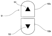
- FIG. 12B is an enlarged view of the zoom button 51.
- the zoom button 51 is a button in which two 1 ⁇ 2 oval areas constituting an enlarge button 52a and a reduce button 52b are arranged.
- the two 1 ⁇ 2 oval regions have a shape obtained by dividing an oval that is slightly smaller than the outer circumference into two in the longitudinal direction, and each 1 ⁇ 2 oval region has a small triangular portion 53 inside.
- the area formed between the enlargement button 52a and the reduction button 52b is transparent so that the image in the right image display area 33 and the frame portion 54 are displayed through.
- the enlargement button 52a and the reduction button 52b Each area is non-transparent. Accordingly, in FIG. 12A, the enlargement button 52a and the reduction button 52b hide the image and the frame portion 54 in the right image display area 33, and in the area other than the enlargement button 52a and the reduction button 52b, And the frame portion 54 are shown through.
- the enlargement button 52a or the reduction button 52b is a button for instructing enlargement or reduction of the right image display area 33.
- the user can enlarge or reduce the images displayed in the left image display area 32 and the right image display area 33 by touching the enlargement button 52a or the reduction button 52b with a finger.
- the zoom button 51 is an instruction button for instructing zooming of the endoscopic image
- the enlargement button 52a is a button for instructing enlargement of the endoscopic image
- the reduction button 52b is instructed to reduce the endoscopic image. Button.
- the zoom button 51 is displayed for a predetermined display time by a timer or the like (not shown) and is not displayed after the predetermined display time has elapsed.
- the ROM 12b stores information on zoom change amounts dg and dh.
- the zoom change amount dg is a change amount during zooming in the left image display area 32.
- the change amount dg is an amount corresponding to a change in the distance between the fingers F4 and F5 when the touch panel 14b is touched in a pinch-in or pinch-out operation. That is, the change amount dg is defined as a change amount function of the distance between the fingers F4 and F5 on the touch panel 14b.
- the zoom change amount dh is a change amount during zooming by the operation of the zoom button 51.
- the change amount dh is an amount corresponding to the number of touches when the finger touches the enlargement button 52a or the reduction button 52b or an amount corresponding to each touch. That is, the change amount dh is defined as a function of the number of times the finger has been touched on the enlargement button 52a or the reduction button 52b. Note that the amount of change dh may be defined as a function of the time of touching the finger enlargement button 52a or the reduction button 52b.
- the display range is enlarged 10 times, while the right image display area In 33, when the user touches the enlarge button 52a once, the change amounts dg and dh are defined so that the display range is enlarged by 1.1 times.
- the user touches the zoom button 51 in the right image display area 33 by zooming in on the display area by zooming in on the left image display area 32 by performing a pinch-in or pinch-out operation to zoom in the display range. Fine zooming is possible.
- the left image display area 32 is a coarse zoom area and the right image display area 33 is a fine zoom area.
- the right image display area 33 is a fine zoom area
- the right image display area 33 may be a coarse zoom area. In that case, when the user touches the right image display area 33, the right image display area 33 is selected as a coarse zoom area, and the display range is finely displayed in areas other than the right image display area 33 (such as the left image display area 32).
- a zoom button 51 for zooming is arranged.
- coarse zoom is performed by a pinch-in or pinch-out operation in the left image display area 32
- fine zoom is performed by the zoom button 51 in the right image display area 33.
- Fine zoom may be performed by a pinch-in or pinch-out operation in the left image display area 32
- coarse zoom may be performed by a zoom button 51 in the right image display area 33.
- the display range is enlarged by 1.1 times
- the change amounts dg and dh are defined so that when the enlargement button 52a is touched once, the display range is enlarged 10 times. According to this configuration, the user can quickly zoom the display range by the enlargement button 52a, and can accurately zoom the display range by a pinch-in or pinch-out operation.
- FIG. 13 is a flowchart illustrating an example of the flow of zoom display processing in the stereo measurement mode.
- FIG. 13 the same processes as those in FIG. 13
- the control unit 12 stores information on the change amount dg that is the left eye image zoom change amount and the change amount dh that is the right eye image zoom change amount in the ROM 12B. (S51).
- the control unit 12 determines whether or not a predetermined operation has been performed on the touch panel 14b (S52). If there is no predetermined operation on the touch panel 14b, the process proceeds to S52a.
- the predetermined operation is the above-described pinch-in or pinch-out operation.
- the control unit 12 determines whether or not the zoom button 51 is already displayed, and after the zoom button 51 is already displayed and the display of the zoom button 51 is started. If the predetermined time has elapsed, the zoom button 51 is hidden (S52a).
- the process of S52a differs between the case where the zoom button 51 is not displayed and the case where the zoom button 51 is already displayed by the process of S55 described later.
- the control unit 12 determines whether or not the zoom button 51 is already displayed, and when the zoom button 51 is already displayed and the predetermined display time of the zoom button 51 has elapsed.
- the zoom button 51 is hidden (S52a). After S52a, the process returns to S1.
- the control unit 12 determines whether the operation is a pinch-in or pinch-out operation in the left image display area 32 (S53a).
- the control unit 12 uses the two fingers F4 in the left image display area 32 based on the change amount dg.
- the zoom processing of the left image display area 32 is performed from the amount of change in the distance between F5 (S54).
- the pinch-in operation the left image display area 32 is reduced, and when the pinch-out operation is performed, the left image display area 32 is enlarged.
- the control unit 12 performs a process related to the display of the zoom button 51.
- This process is performed when the zoom button 51 is not displayed by the first process or the like and when the zoom button 51 is already displayed in the second and subsequent processes. It differs depending on whether it is displayed.
- the zoom button 51 is not displayed due to the first processing or the like, the zoom button is superimposed and displayed across the frame portion 54 of the right image display area 33 at the lower right of the right image display area 33. If the zoom button 51 has already been displayed in the second and subsequent processing, it is updated so as to extend the display time (S55).
- control unit 12 zooms the right image display area 33 by the zoom amount of the left image display area 32 (S56).
- the right image display area 33 is also zoomed by the same amount as the left image display area 32.
- the control unit 12 zooms the right image display area 33 and then recalculates the display range of the right image display area 33 corresponding to the display range of the left image display area 32 by matching processing (S57).
- control unit 12 redisplays the display range of the right image display area 33 corrected by recalculation (S58).
- the recalculation of the display range of the right image display area 33 is performed after zooming the right image display area 33 (S56), but the display range of the right image display area 33 is recalculated in S56.
- the right image display area 33 may be zoomed while correcting by calculation.
- the control unit 12 When the operation in S53a is not a pinch-in or pinch-out operation in the left image display area 32 (S53a: NO), the control unit 12 further performs an enlargement button 52a or a reduction in the zoom button 51 of the right image display area 33 in S53a. It is determined whether the touch operation is on the button 52b (S53b). When the operation in S53b is not a touch operation of the enlarge button 52a or the reduce button 52b in the right image display area 33 (S53b: NO), the process returns to S52.
- the control unit 12 determines which of the enlargement button 52a and the reduction button 52b is touched, and enlarges the display range of the left image display area 32 when the enlargement button 52a is touched based on the change amount dh.
- the reduction button 52b is touched, the left image display area 32 is reduced (S59).
- the control unit 12 updates the display time of the zoom button 51 to be extended (S60).
- the processing in FIG. 13 ends when the user instructs the end of the stereo measurement processing mode on the menu screen.
- the operation from S54 to S60 receives an operation instruction for a zoom operation such as a pinch-in or pinch-out operation while the left image display region 32 is selected
- the left image display region 32 and the right image display are displayed.
- the display range of the area 33 is changed by the change amount dg and an operation instruction such as a touch operation of the zoom button 51 is received while the right image display area 33 is selected
- a display control unit is configured to perform display control so that the display range 33 is changed by a change amount dh different from the change amount dg.
- the change amount dg is set to be larger than the change amount dh
- the user performs a pinch-in or pinch-out operation in the left image display area 32 by repeating the processing of FIG.
- a coarse zoom that greatly changes the display range of the left image display region 32 and the display range of the right image display region 33, and the display range of the left image display region 32 and the right by touching the zoom button 51 of the right image display region 33
- the fine zoom for changing the display range of the image display area 33 to be small can be repeated one or more times.
- the user can quickly and accurately zoom the display range of the left image display area 32 and the display range of the right image display area 33 to a desired size.
- the cursor display process of the first embodiment or the third embodiment described above, the zoom process of the second embodiment, or the zoom process of the fourth embodiment You may be able to do both.
- the change amounts da, db, de, and df may be different according to the zoom amount of the endoscopic image.
- the cursor display process or the zoom process is executed in the stereo measurement mode, but the same endoscopic image is displayed in the two image display areas in other modes other than the stereo measurement mode.
- the cursor display process or zoom process described above may be executed even during the time. For example, it is convenient when a certain point is specified quickly and accurately on the same endoscopic image, when a certain point is marked quickly and accurately, or when zooming is performed quickly and accurately.
- the endoscope apparatus 1 displays two image display areas on the display unit 14, but may display three or more image display areas. In that case, the change amount of the cursor and the change amount at the time of zooming differ between the plurality of image display areas.
- the display magnification of the third image display area is set to the left image display area 32 and the right image display area.
- the movement amount or zoom amount of the point in the third image display area is the movement amount or zoom amount of the point in the left image display area 32 and the right image display area 33. Different.
- the cursor movement operation and the zoom operation described above use a touch panel.
- the measurement point specifying operation is performed using the joystick of the operation unit 15, and the zoom operation is performed using the operation unit 15. You may make it perform using the zoom operation button provided in.
- the direction of the joystick can be specified depending on the tilting direction.
- the cursor 35 a on the left image display area 32 when the cursor 35 a on the left image display area 32 is dragged, the finger F moves beyond the left image display area 32 or the cursor on the right image display area 33.
- the finger F moves beyond the right image display area 33 when the drag operation is performed on 35b, when the drag operation is performed beyond the image display area first touched by the finger F, It has been described that the cursor 35a and 35b may be moved by continuously using the change value for the image display area touched by the finger F first.
- the cursor 35a moves or zooms large in the left image display area 32, and the cursor 35b moves small or zooms small in the right image display area 33, but the left image display area In 32, the cursor 35a may move small or the zoom amount may be small, and in the right image display area 33, the cursor 35b may move large or the zoom amount may be large.
- two inspectors who face each other may view an image displayed on one display unit of the endoscope apparatus.
- some endoscope apparatuses can change (that is, invert) the orientation of the screen of the display unit by 180 degrees.
- the screen direction of the display unit is changed by 180 degrees (that is, inverted), the vertical direction of the screen of the display unit is reversed.
- the left and right image display areas may be interchanged.
- the data of the respective change amounts da, db, dc, dd, df, dg, and dh are stored in the ROM 12b, but are stored in a memory card or the like, and the memory card I / F 17 You may read out via. If the memory card is a rewritable memory, for example, a flash memory, the value of each change amount da, db, dc, dd, df, dg, dh may be changed by the user.
- the move button is displayed by touching the right image display area or the left image display area and is not displayed after a predetermined time has elapsed, but the move button is displayed or not displayed. It is good also as a structure provided with the switch button to be made. According to this configuration, the user can freely switch between display and non-display of the movement button, improve the operability of the movement button, and consequently specify the position of a measurement point or the like in the endoscopic image with a small number of operations. Can be done quickly. Even when the movement button is switched to be displayed, the movement button is automatically hidden during the touch operation so that the movement button does not hinder the movement during the movement.
- the zoom button is displayed by touching the right image display area or the left image display area and is not displayed after a predetermined time has elapsed, but the zoom button is displayed or not displayed. It is good also as a structure provided with the switch button to be made. According to this configuration, the user can freely switch between displaying and hiding the zoom button, improving the operability of the zoom button, and, in turn, quickly changing the display range of the endoscope display with a small number of operations. It can be carried out. Even when the zoom button is switched to display, the zoom button is automatically hidden during the touch operation so that the zoom button is not hindered.
- each “unit” in this specification is a conceptual one corresponding to each function of the embodiment, and does not necessarily correspond to a specific hardware or software routine on a one-to-one basis.
- each step of each procedure in the present embodiment may be executed in a different order for each execution by changing the execution order and performing a plurality of steps at the same time, as long as it does not contradict its nature.
- all or a part of each step of each procedure in the present embodiment may be realized by hardware.
- an endoscope image display device an endoscope image display method, and an endoscope image display program can be provided.
Landscapes
- Engineering & Computer Science (AREA)
- Signal Processing (AREA)
- Health & Medical Sciences (AREA)
- Life Sciences & Earth Sciences (AREA)
- Multimedia (AREA)
- Surgery (AREA)
- Physics & Mathematics (AREA)
- Heart & Thoracic Surgery (AREA)
- Molecular Biology (AREA)
- Biophysics (AREA)
- Nuclear Medicine, Radiotherapy & Molecular Imaging (AREA)
- Optics & Photonics (AREA)
- Pathology (AREA)
- Radiology & Medical Imaging (AREA)
- Veterinary Medicine (AREA)
- Biomedical Technology (AREA)
- Public Health (AREA)
- General Health & Medical Sciences (AREA)
- Animal Behavior & Ethology (AREA)
- Medical Informatics (AREA)
- General Physics & Mathematics (AREA)
- Theoretical Computer Science (AREA)
- Computer Vision & Pattern Recognition (AREA)
- Human Computer Interaction (AREA)
- Business, Economics & Management (AREA)
- Marketing (AREA)
- Instruments For Viewing The Inside Of Hollow Bodies (AREA)
- Endoscopes (AREA)
Abstract
内視鏡装置1は、左画像表示領域32と右画像表示領域33を有するタッチパネル付き表示部14と、制御部12を有する。制御部12は、左画像表示領域32が選択されているときに、ドラッグ操作指示を受けると、左画像表示領域32及び右画像表示領域33に表示されているカーソル35aと35bの位置を変化量daだけ変化させ、右画像表示領域33が選択されているときに、ドラッグ操作指示を受けると、左画像表示領域32及び右画像表示領域33に表示されているカーソル35aと35bの位置を変化量だとは異なる変化量dbだけ変化させるように表示制御を行う。
Description
本発明は、内視鏡画像表示装置、内視鏡画像表示方法及び内視鏡画像表示プログラムに関し、特に、少なくとも2つの内視鏡画像を表示する内視鏡画像表示装置、内視鏡画像表示方法及び内視鏡画像表示プログラムに関する。
従来より、内視鏡装置が、工業分野及び医療分野で広く利用されている。内視鏡装置では、挿入部の先端部に設けられた観察窓を通して得られた被写体の内視鏡画像がモニタに表示され、検査者であるユーザはモニタを見ながら被写体の検査をすることができ、かつ記憶装置に記録することもできる。
内視鏡装置には、種々のタイプがあり、例えば、ステレオ計測機能を有する内視鏡がある。ステレオ計測機能を有する内視鏡装置を利用すれば、挿入部の先端から被写体上の指定した点までの距離を計測したり、被写体上で指定した2点間の距離を計測することができる。
ところで、最近は、タッチパネル付きの表示装置を有するカーナビ装置、ゲーム機などが普及し、ユーザは、指などで、その表示装置の画面を触れるだけで、メニュー画面上の機能を選択したり、画面上のカーソルの位置を移動させたり、画面の表示範囲を変更したりすることができる。
さらに、タッチパネル付きの表示装置を有する装置の操作性の向上のための種々の提案がされている。例えば、特開2006-226820号公報には、スクロール速度を任意にかつ自由に変えることができる、タッチパネル付きのナビゲーション装置が提案されている。その提案のナビゲーション装置では、速度目印としてのスクロール速度指定アイコンが画面上に表示され、ユーザは、そのアイコンを触れて指示を与えることにより、地図をスクロールするときのスクロール速度を所望の速度に変更することができる。
内視鏡装置は、基本的に、各種検査や各種計測のために用いられるため、表示装置の画面上に表示された被写体上の点を計測点として指定を行うときにはジョイスティックなどの操作器に対する慎重な操作が、ユーザに要求される。
同様に、従来の内視鏡装置では、表示装置の画面上における内視鏡画像の表示範囲の変更はズーム機能などにより実現されるが、その表示範囲の変更を正確に行うときにもジョイスティックなどの操作器を慎重に操作しなければならず、ユーザに煩雑な操作が要求される。
上述したタッチパネル付きの表示装置は、内視鏡装置にも適用可能である。タッチパネル付きの表示装置は、メニュー画面上の機能選択などが簡単にできるので、ユーザにとっては操作性がよい。
しかし、タッチパネル付きの表示装置を内視鏡装置に適用した場合、ユーザが計測点位置の指定あるいは表示範囲のズーミングを迅速かつ正確に指定するためには、カーソルなどのマークを計測点位置の近傍まで大きく移動させたり、あるいは表示範囲を大きく変化させたりするだけでなく、そのマークを所望の位置に少しだけ移動させたり、あるいは表示範囲を少しだけ変化させることの両方の操作指示が、迅速に行われる必要がある。
上記の提案のナビゲーション装置の技術を内視鏡装置に適用することも考えられるが、上記の提案のナビゲーション装置の場合、スクロール速度を変更する度に、ユーザは、上述したスクロール速度指定アイコンを触れて速度変更の指示を与える操作を行わなければならず、計測点などの位置の指定を迅速に行うことができない。
そこで、本発明は、少なくとも2以上の内視鏡画像において計測点などの位置の指定あるいは画面上に表示される内視鏡画像の表示範囲の変更を少ない操作回数で迅速に行うことができる内視鏡画像表示装置、内視鏡画像表示方法及び内視鏡画像表示プログラムを提供することを目的とする。
本発明の一態様によれば、内視鏡画像を表示するための第1の画像表示領域と第2の画像表示領域を有する表示装置と、前記第1の画像表示領域と前記第2の画像表示領域のいずれか1つを選択する選択部と、前記選択部により前記第1の画像表示領域が選択されているときに、第1の操作指示を受けると、前記第1の画像表示領域及び前記第2の画像表示領域に表示されているマークの位置又は画像の表示範囲を第1の変化量だけ変化させ、前記選択部により前記第2の画像表示領域が選択されているときに、第2の操作指示を受けると、前記第1の画像表示領域及び前記第2の画像表示領域に表示されている前記マークの位置又は前記画像の表示範囲を前記第1の変化量とは異なる第2の変化量だけ変化させるように表示制御を行う表示制御部と、を有する内視鏡画像表示装置を提供することができる。
本発明の一態様によれば、内視鏡画像を表示するための第1の画像表示領域と第2の画像表示領域を有する表示装置における前記第1の画像表示領域と前記第2の画像表示領域のいずれか1つを選択し、前記第1の画像表示領域が選択されているときに、第1の操作指示を受けると、前記第1の画像表示領域及び前記第2の画像表示領域に表示されているマークの位置又は画像の表示範囲を第1の変化量だけ変化させ、前記第2の画像表示領域が選択されているときに、第2の操作指示を受けると、前記第1の画像表示領域及び前記第2の画像表示領域に表示されている前記マークの位置又は前記画像の表示範囲を前記第1の変化量とは異なる第2の変化量だけ変化させるように表示制御を行う、内視鏡画像表示方法を提供することができる。
本発明の一態様によれば、内視鏡画像を表示するための第1の画像表示領域と第2の画像表示領域を有する表示装置における前記第1の画像表示領域と前記第2の画像表示領域を表示するためのプログラムであって、前記第1の画像表示領域と前記第2の画像表示領域のいずれか1つを選択する機能と、前記第1の画像表示領域が選択されているときに、第1の操作指示を受けると、前記第1の画像表示領域では、前記第1の画像表示領域及び前記第2の画像表示領域に表示されているマークの位置又は画像の表示範囲を第1の変化量だけ変化させ、前記第2の画像表示領域が選択されているときに、第2の操作指示を受けると、前記第2の画像表示領域では、前記第1の画像表示領域及び前記第2の画像表示領域に表示されている前記マークの位置又は前記画像の表示範囲を前記第1の変化量とは異なる第2の変化量だけ変化させるように表示制御を行う機能と、をコンピュータに実現させるための内視鏡画像表示プログラムを提供することができる。
以下、図面を参照して本発明の実施の形態を説明する。
(第1の実施の形態)
(構成)
図1は、本実施の形態に係わる内視鏡装置の構成を示すブロック図である。内視鏡装置1は、内視鏡2と、内視鏡2が接続される装置本体3とを有して構成される。内視鏡2は、装置本体3に対して着脱可能に構成されている。内視鏡2は、挿入部の先端部に設けられた観察窓を介して得られた被写体の撮像信号を装置本体3へ出力する。
(構成)
図1は、本実施の形態に係わる内視鏡装置の構成を示すブロック図である。内視鏡装置1は、内視鏡2と、内視鏡2が接続される装置本体3とを有して構成される。内視鏡2は、装置本体3に対して着脱可能に構成されている。内視鏡2は、挿入部の先端部に設けられた観察窓を介して得られた被写体の撮像信号を装置本体3へ出力する。
内視鏡装置1は、通常の観察機能に加えて、ステレオ計測機能を有している。よって、内視鏡2は、図示しない挿入部を有し、挿入部の先端部には、ステレオ計測を行うときに使用されるための光学アダプタ4が着脱可能になっている。光学アダプタ4は、2つの観察窓を有し、内視鏡2の挿入部の撮像素子の撮像面に、互いに視差を有する被写体の2つの光学像を与える。光学アダプタ4は、内視鏡2あるいは装置本体3が、内視鏡2の挿入部の先端に光学アダプタ4が装着されたことを検出できるようにするための接点(図示せず)を有している。
装置本体3は、カメラコントロールユニット(以下、CCUという)11と、制御部12と、映像信号処理回路13と、タッチパネル付き表示部(以下、表示部という)14と、操作部15と、LANインターフェース(以下、LAN I/Fと略す)16と、メモリカードインターフェース(以下、メモリカードI/Fと略す)17と、USBインターフェース(以下、USB I/Fと略す)18と、音声信号処理回路19と、スピーカ20と、マイク21を含んで構成されている。
CCU11は、制御部12の制御の下、内視鏡2の撮像素子(図示せず)を駆動すると共に、撮像素子から出力される撮像信号を受信して映像信号処理回路13へ出力する。
制御部12は、装置本体3内の各種回路からの信号を受信すると共に、各種回路への制御信号を出力する。制御部12は、中央処理装置(以下、CPUという)12a、ROM12b及びRAM12cを含む。
制御部12は、装置本体3内の各種回路からの信号を受信すると共に、各種回路への制御信号を出力する。制御部12は、中央処理装置(以下、CPUという)12a、ROM12b及びRAM12cを含む。
ROM12bには、各種プログラムと各種設定データが記憶されている。各種設定データの中には、後述するカーソルの変化量da,dbも含まれている。ここでは、変化量da,dbは、後述するドラッグ操作等における、LCD14a(すなわちタッチパネル)に触れている時の指Fの単位移動距離に応じた量である。すなわち、各変化量da,dbは、指FのLCD14a上の移動距離の関数として規定される。なお、各変化量da,dbは、指FのLCD14a上の移動速度の関数として規定してもよい。
また、制御部12は、内視鏡2を介する光学アダプタ4の接点の導通状態信号に基づき、光学アダプタ4が内視鏡2の挿入部の先端に装着されたか否かを判定することができる。
また、制御部12は、内視鏡2を介する光学アダプタ4の接点の導通状態信号に基づき、光学アダプタ4が内視鏡2の挿入部の先端に装着されたか否かを判定することができる。
映像信号処理回路13は、CCU11からの撮像信号を処理して画像信号を生成し、表示部14へ出力する。映像信号処理回路13は、制御部12の制御の下、各種機能に応じた画像処理を実行する。ステレオ計測機能が実行されるとき、映像信号処理回路13は、互いに視差のある2つの内視鏡画像を生成し、表示部14へ出力する。すなわち、内視鏡装置1は、内視鏡画像表示装置である。
表示部14は、液晶表示器(LCD)14aと、タッチパネル14bを有している。タッチパネル14bは、例えば静電方式のタッチパネルであり、液晶表示器14aの表示画面上に密着して設けられている。タッチパネル14bからの位置信号は、制御部12へ出力される。
操作部15は、フリーズボタン、レリーズボタン、ジョイスティック、ズーム操作ボタン、メニューボタンなどの複数の操作器を有する。
LAN I/F16は、ローカルエリアネットワーク(以下、LANという)との接続のためのインターフェースである。内視鏡装置1は、LAN I/F16を介してLANに接続された外部機器と通信を行うことができる。
LAN I/F16は、ローカルエリアネットワーク(以下、LANという)との接続のためのインターフェースである。内視鏡装置1は、LAN I/F16を介してLANに接続された外部機器と通信を行うことができる。
メモリカードI/F17は、記憶媒体としてのメモリカードを装着するためのインターフェースである。内視鏡装置1は、メモリカードI/F17を介してメモリカードへの内視鏡画像の記録、及びメモリカードからのデータの読み込みを行うことができる。
USB I/F18は、USB(Universal Serial Bus)ケーブルあるいはUSB機器を接続するためのインターフェースである。内視鏡装置1は、USB I/F18を介してUSB機器への内視鏡画像の記録、及びUSB機器からのデータの読み込みを行うことができる。
音声信号処理回路19は、制御部12の制御の下、制御部12からの音声信号を処理して、スピーカ20から音声を出力させ、かつマイク21からの音声信号を処理して制御部12へ出力する。内視鏡装置1は、内視鏡画像と共に、音声も記録し、再生することができる。
検査者であるユーザは、タッチパネル14bあるいは操作部15を操作することにより、内視鏡装置1の各種機能を実行させることができる。制御部12は、タッチパネル14bあるいは操作部15において指示されたコマンドに応じて、所定のプログラムをROM12bから読み出して、RAM12cを作業領域として使用しながら実行することにより、内視鏡画像をLCD14aに表示したり、得られた内視鏡画像をメモリカードに記録したりすることができる。さらに、ユーザは、光学アダプタ4を内視鏡2の挿入部の先端部に装着し、LCD14aの画面上に表示されたメニュー画面から所望のコマンドを選択して実行を指示することで、内視鏡装置1にステレオ計測機能を実行させることもできる。
(ステレオライブ画像の構成)
次に、ステレオ計測機能が実行されているときにおける表示部14に表示される内視鏡画像について説明する。
次に、ステレオ計測機能が実行されているときにおける表示部14に表示される内視鏡画像について説明する。
図2Aから図2Cは、ステレオ計測モード時における表示部14に表示されるステレオライブ画像の例を示す図である。図2Aの画面31は、ステレオライブ画像が表示される2つの画像表示領域32と33を含むグラフィカル・ユーザ・インターフェース(GUI)である。LCD14aに表示される画面31は、左眼画像と右眼画像の2つの画像を表示する2つの画像表示領域を有する。よって、表示部14は、内視鏡画像を表示するための左画像表示領域32と右画像表示領域33を有する表示装置である。
2つの画像表示領域の内の左画像表示領域32は、左眼画像を表示し、右画像表示領域33は、右眼画像を表示する。光学アダプタ4により、内視鏡2は、左右の画像を含む撮像信号を生成し、装置本体3では、受信した撮像信号から左眼画像と右眼画像が生成され、LCD14aに表示される。
なお、ここでは、左画像表示領域32と右画像表示領域33が表示部14のLCD14aの1つの表示部に表示されているが、2つの表示装置を用いて、左画像表示領域32と右画像表示領域33を別々の表示装置に表示するようにしてもよい。
また、左画像表示領域32と右画像表示領域33の大きさが同じである必要はない。例えば、図2Bに示す他の例のように、左画像表示領域32を画面31上に大きく表示させ、右画像表示領域33を確認用画像として小さく表示させてもよい。
さらにまた、図2Cに示す他の例のように、左画像表示領域32と右画像表示領域33を90度回転させ、左画像表示領域32を画面31に合わせて拡大させ、右画像表示領域33を確認用画像として左画像表示領域32上に小さく表示させてもよい。
ユーザは、ステレオ計測モードにおいて計測点を指定することができる。例えば、画面上に計測点を指定するためのマークとしてのカーソルを表示させ、タッチパネル14b上で、指でドラッグ操作などすることによって、カーソルを所望の位置に移動させ、計測点を指定することができる。ユーザは、左画像表示領域32に表示された左眼画像用のカーソル35aと右画像表示領域33に表示された右眼画像用のカーソル35bのいずれでも移動させることができる。
以下、カーソルの移動は、左画像表示領域32あるいは右画像表示領域33上の移動させたいカーソルを、ユーザが指で長押しした後に触れながら移動させた方向に動かすドラッグ操作により行う場合で本実施の形態を説明するが、カーソルの移動は、例えば移動させたいカーソルを画面上でダブルタップして指定した後、画面上でのスワイプ操作(すなわち触れる箇所を特定しないで画面を指で触れながらカーソルを移動させたい方向に動かす操作)、フリック操作(短い距離を弾くようにさっと動かす操作)等の操作によって、行ってもよい。
図2Aから図2Cでは、計測点指定用のマークであるカーソル35aと35bが、それぞれ、画像表示領域32と33に表示されている。因みに、図2Aから図2Cでは、LCD14aには、ジェットエンジン内のブレードBの一部が表示されている。
左画像表示領域32に表示される内視鏡画像と、右画像表示領域33に表示される内視鏡画像は、ステレオ計測用の左右の内視鏡画像であり、互いに視差を有する画像である。
左画像表示領域32に表示される内視鏡画像と、右画像表示領域33に表示される内視鏡画像は、ステレオ計測用の左右の内視鏡画像であり、互いに視差を有する画像である。
カーソル35aの位置とカーソル35bの位置は、2つの内視鏡画像の視差に応じた位置に表示される。よって、左画像表示領域32内のカーソル35aの位置を移動させると、右画像表示領域33内のカーソル35bの位置も移動するが、カーソル35bの位置は、カーソル35aにより示される被写体上の位置に対応する、右眼画像上の位置がマッチング処理により計算された位置である。同様に、右画像表示領域33内のカーソル35bの位置を移動させると、左画像表示領域32内のカーソル35aの位置も移動するが、カーソル35aの位置は、カーソル35bにより示される被写体上の位置に対応する、左眼画像上の位置がマッチング処理により計算された位置である。
なお、以下では、1つの計測点が指定される場合を例として説明するが、2点間の距離を計測する場合は、2つの計測点が指定される。
(作用)
次に、本実施の形態の内視鏡装置1の動作について説明する。図3は、ステレオ計測モード時における、カーソルの表示処理の流れの例を示すフローチャートである。図3の処理は、ステレオ計測用の光学アダプタ4が挿入部の先端部に装着されたときに、制御部12のCPU12aがROM12bからカーソル表示処理プログラムを読み出して実行することにより、行われる。
光学アダプタ4が装着されると、制御部12は、映像信号処理回路13に対して指示を出力して、図2Aから図2Cに示すようなステレオライブ画像をLCD14aに表示させる(S1)。
次に、本実施の形態の内視鏡装置1の動作について説明する。図3は、ステレオ計測モード時における、カーソルの表示処理の流れの例を示すフローチャートである。図3の処理は、ステレオ計測用の光学アダプタ4が挿入部の先端部に装着されたときに、制御部12のCPU12aがROM12bからカーソル表示処理プログラムを読み出して実行することにより、行われる。
光学アダプタ4が装着されると、制御部12は、映像信号処理回路13に対して指示を出力して、図2Aから図2Cに示すようなステレオライブ画像をLCD14aに表示させる(S1)。
次に、制御部12は、ステレオ計測モードが設定されたか否かを判定する(S2)。ステレオ計測モードの設定は、ユーザがメニュー画面からステレオ計測モードを選択することによって行われる。
ステレオ計測モードが設定されないときは(S2:NO)、処理は、S1に戻る。ステレオ計測モードが設定されると(S2:YES)、制御部12は、左眼画像用のカーソル35aの変化量daと、右眼画像用のカーソル35bの変化量dbの情報をROM12bから読み出す。
制御部12は、タッチパネル14bに対する所定の操作があったか否かを判定する(S4)。タッチパネル14bに対する所定の操作がなければ、処理は、S1に戻る。所定の操作とは、ここでは、長押しした後に指Fを移動させるドラッグ操作である。すなわち、左眼画像用のカーソル35aあるいは右眼画像用のカーソル35bに指Fを触れながらタッチパネル14b上を移動させるドラッグ操作が行われたかが判定される。
タッチパネル14bに対する所定の操作が行われると(S4:YES)、制御部12は、その操作が、左画像表示領域32上で行われた操作であるかを判定する(S5)。
タッチパネル14bに対する所定の操作が行われると(S4:YES)、制御部12は、その操作が、左画像表示領域32上で行われた操作であるかを判定する(S5)。
よって、S4とS5の処理が、左画像表示領域32と右画像表示領域33のいずれか1つを選択する選択部を構成する。すなわち、カーソル35aあるいは35b等へのタッチにより、左画像表示領域32と右画像表示領域33のいずれか1つの選択がされる。
なお、左画像表示領域32と右画像表示領域33のいずれか1つの選択は、選択する画像表示領域へタッチ、あるいはメニュー画面上での選択により行うようにしてもよい。その場合は、選択する画像表示領域へタッチあるいはメニュー画面による選択結果に応じて、左画像表示領域32と右画像表示領域33のいずれか1つの選択が行われるので、選択する画像表示領域へのタッチ検出処理、及びメニュー画面とそのジョイスティックなどによる選択指示入力処理が、選択部を構成する。
S4における操作が左眼画像用のカーソル35aへの操作であるとき(S5:YES)、制御部12は、カーソル35aの移動量(すなわち表示部14上でカーソル35aがドラッグ操作により移動した距離)から、変化量da に基づいて左眼画像用のカーソル35aを左画像表示領域32内で移動させる(S6)。
図4は、ユーザの指Fが左眼画像用のカーソル35aにタッチしている状態を示す図である。ユーザは、指Fをタッチパネル14bに触れている状態から、左眼画像用のカーソル35aを移動させたい方向に動かすドラッグ操作を行う。ドラッグ操作における指Fの位置の変化は制御部12に入力されているので、制御部12は、ドラッグ操作における指Fの移動量を算出することができる。
例えば、ユーザが左眼画像用のカーソル35aを移動させたい方向として、図4において点線で示す方向に指Fをドラッグしたとする。移動後の指Fを指F´とする。S6では、制御部12は、ドラッグ方向(点線で示す方向)に、左眼画像用のカーソル35aを、変化量daに基づいて指Fの移動距離から決定された量だけ左画像表示領域32内で移動させる。例えば、変化量daがLCD14a上の1cmに設定され、指FがLCD14a上で1cm動かされたときは、指Fをタッチパネル14b上で1cmの距離だけドラッグすると、左眼画像用のカーソル35aは、LCD14a上でドラッグ方向に1cm移動する。移動後のカーソル35aをカーソル35a´とする。
S6の後、制御部12は、左眼画像用のカーソル35aの移動量分に応じた距離だけ、右眼画像用のカーソル35bを右画像表示領域33内で移動させる(S7)。上記の例の場合、左画像表示領域32内で左眼画像用のカーソル35aがタッチパネル14b上で1cmの距離だけ移動すると、右眼画像用のカーソル35bも、右画像表示領域33内でドラッグ方向に1cm移動する。移動後のカーソル35bをカーソル35b´とする。
制御部12は、右画像表示領域33内で右眼画像用のカーソル35bを移動させた後、左画像表示領域32内での左眼画像用のカーソル35aの位置に対応した、右画像表示領域33内での右眼画像用のカーソル35bの位置をマッチング処理により再計算する(S8)。
なお、ここでは、右眼画像用のカーソル35bの位置の再計算は、右画像表示領域33内で右眼画像用のカーソル35bを移動した後(S7)、行われているが、S7において、右眼画像用のカーソル35bの位置の再計算による補正をしながら、右画像表示領域33内で右眼画像用のカーソル35bを移動するようにしてもよい。
S8の後、制御部12は、再計算された右画像表示領域33内の補正された位置に、右眼画像用のカーソル35bを再表示する(S9)。
S9の後、処理は、S4に戻る。
S9の後、処理は、S4に戻る。
S4における操作が右眼画像用のカーソル35bへの操作であるとき(S5:NO)、制御部12は、右眼画像用のカーソル35bの移動量(すなわち表示部14上でカーソル35bがドラッグ操作により移動した距離)から、変化量dbに基づいて右眼画像用のカーソル35bを右画像表示領域33内で移動させる(S10)。
図5は、ユーザの指Fが右眼画像用のカーソル35bにタッチしている状態を示す図である。ユーザは、指Fをタッチパネル14bに触れている状態から、右眼画像用のカーソル35bを移動させたい方向に動かすドラッグ操作を行う。
例えば、ユーザが右眼画像用のカーソル35bを移動させたい方向として、図5において点線で示す方向に指Fをドラッグしたとする。移動後の指Fを指F´とする。S10では、制御部12は、ドラッグ方向(点線で示す方向)に、右眼画像用のカーソル35bを、変化量dbに基づいて指Fの移動距離から決定された量だけ右画像表示領域33内で移動させる。例えば、変化量dbがLCD14a上の0.1cmに設定され、指FがLCD14a上で1cm動かされたときは、指Fをタッチパネル14b上で1cmの距離だけドラッグすると、右眼画像用のカーソル35bは、LCD14a上でドラッグ方向に0.1cm移動する。移動後のカーソル35bをカーソル35b´とする。図5に示すように、移動後の指F´の位置と移動後のカーソル35b´の位置は異なっている。
S10の後、制御部12は、右眼画像用のカーソル35bの移動量分に応じた距離だけ、左眼画像用のカーソル35aを左画像表示領域32内で移動させる(S11)。上記の例の場合、右画像表示領域33内で右眼画像用のカーソル35bがタッチパネル14b上で1cmの距離だけ移動すると、左眼画像用のカーソル35aも、左画像表示領域32内でドラッグ方向に0.1cm移動する。移動後のカーソル35aをカーソル35a´とする。
制御部12は、左画像表示領域32内で左眼画像用のカーソル35aを移動させた後、右画像表示領域33内での右眼画像用のカーソル35bの位置に対応した、左画像表示領域32内での左眼画像用のカーソル35aの位置をマッチング処理により再計算する(S12)。
なお、ここでは、左眼画像用のカーソル35aの位置の再計算は、左画像表示領域32内で左眼画像用のカーソル35aを移動した後(S11)、行われているが、S11において、左眼画像用のカーソル35aの位置の再計算による補正をしながら、左画像表示領域32内で左眼画像用のカーソル35aを移動するようにしてもよい。
S12の後、制御部12は、再計算された左画像表示領域32内の補正された位置に、左眼画像用のカーソル35aを再表示する(S13)。
S13の後、処理は、S4に戻る。
図3の処理は、ユーザがメニュー画面上でステレオ計測処理モードの終了を指示すると、処理は、終了する。
S13の後、処理は、S4に戻る。
図3の処理は、ユーザがメニュー画面上でステレオ計測処理モードの終了を指示すると、処理は、終了する。
以上のように、S6からS13の処理が、左画像表示領域32が選択されているときに、ドラッグ操作による所定の操作指示を受けると、左画像表示領域32及び右画像表示領域33に表示されているマークとしての各カーソル35aと35bの位置を変化量daだけ変化させ、右画像表示領域33が選択されているときに、ドラッグ操作による所定の操作指示を受けると、左画像表示領域32及び右画像表示領域33に表示されているマークとしての各カーソル35aと35bの位置を変化量daとは異なる変化量dbだけ変化させるように表示制御を行う表示制御部を構成する。
上述した例では、変化量daは変化量dbよりも大きく設定されているため、図3の処理が繰り返されることによって、ユーザは、左画像表示領域32内をタッチすることによるカーソル35aと35bを大きく移動させる粗動と、右画像表示領域33内をタッチすることにようカーソル35aと35bを小さく移動させる微動とを、それぞれ1回以上繰り返すことができる。よって、ユーザは、所望の位置へカーソル35aと35bを迅速かつ正確に移動させることができる。
図6は、カーソルの移動を説明するための図である。ユーザがカーソル35a及び35bを所望の位置P1に移動させたいとすると、ユーザは、上述したドラッグ操作により、上述した粗動と微動の操作を何回か行うことにより、カーソル35a及び35bを所望の位置P1に少ない操作回数で簡単かつ迅速に移動させることができる。
図7は、カーソルの移動の他の例を説明するための図である。図7は、画面上で任意の位置を触れながらカーソルを移動させたい方向に動かす方法による場合を示す。
図7の場合、ユーザは、カーソル35aと35bを移動させたい方向における任意の位置で指Fをタッチさせると、カーソル35aと35bは指の方向に向かって移動する。例えば、図7において、左画像表示領域32内でカーソル35aを移動させたい方向に指Fをタッチするとカーソル35aは指Fの方向に移動する。カーソル35aは指Fの位置まで移動すると停止する。カーソル35aが指Fに向かって移動中に指Fを移動させると、指Fが移動した先に向かってカーソル35aは移動する。カーソル35aが指Fに向かって移動中に指Fを離すとカーソル35aは停止する。カーソル35aの移動、停止に合わせてカーソル35bも移動、停止する。左画像表示領域32内でタッチするとカーソル35aと35bは粗動し、右画像表示領域33内でタッチするとカーソル35aと35bは微動する。
なお、図2Bあるいは図2Cに示すように、画面31上に表示された左画像表示領域32と右画像表示領域33の大きさが異なる場合は、その2つの領域の大きさの違いに比例して、各変化量に基づく各カーソルの移動量は、変更される。
なお、図7において、左画像表示領域32内でカーソル35aを移動させたい方向に指Fをタッチした状態から、指Fを別の位置に移動させる場合、指Fが左画像表示領域32を越えて移動してしまったり、図5において、右画像表示領域33上のカーソル35bをドラッグ操作するとき、指Fが右画像表示領域33を超えて移動してしまったりする場合が考えられる。
そのような場合は、指Fがタッチパネル14bから離れないでドラッグ操作が継続して行われているときは、最初に指Fが触れた左画像表示領域32用の変化量daあるいは右画像表示領域33用の変化量dbに基づいて、最初に指Fが触れた画像表示領域を超えても、カーソル35a及び35bを移動させる。すなわち、最初に指Fが触れた画像表示領域を超えて操作が行われているときには、最初に指Fが触れた画像表示領域用の変化量の値を引き続き使用して、カーソル35aと35bの移動を行う。
すなわち、S6からS13の処理において、左画像表示領域32が選択されているときになされた操作の操作指示が左画像表示領域32を超えた領域においても継続しているときには、継続してカーソル35aの位置を変化量daに基づいて変化し、右画像表示領域33が選択されているときになされた操作指示が右画像表示領域33を超えた領域においても継続しているときには、継続してカーソル35bの位置を変化量dbに基づいて変化するようにしてもよい。
以上のように、上述した実施の形態によれば、少なくとも2以上の内視鏡画像において計測点などの位置の指定を少ない操作回数で迅速に行うことができる内視鏡画像表示装置を提供することができる。
また、表示部14上で2つの画像表示領域の一方上でカーソルの移動操作を行っていても、少なくとも2つの画像表示領域の他方が指Fあるいは手で隠れることはないので、ユーザは、画像表示領域上のカーソルの位置を確実に認識することができる。また、図7のように画面上の任意の位置を触れてカーソルを操作する場合は、2つの画像表示領域上のカーソルの位置を認識することができる。
(第2の実施の形態)
本実施の形態は、内視鏡画像の拡大及び縮小表示の操作に関する。ユーザは、内視鏡画像を拡大して見たい場合もあれば、縮小して全体を見たい場合もある。さらに、計測点の指定の場合にも、内視鏡画像の表示範囲を拡大したり縮小したりしながら、計測点の指定を行いたい場合もある。本実施の形態は、そのような内視鏡画像の表示範囲の変更操作を少ない操作回数で迅速に行うことができる内視鏡装置に関する。
本実施の形態は、内視鏡画像の拡大及び縮小表示の操作に関する。ユーザは、内視鏡画像を拡大して見たい場合もあれば、縮小して全体を見たい場合もある。さらに、計測点の指定の場合にも、内視鏡画像の表示範囲を拡大したり縮小したりしながら、計測点の指定を行いたい場合もある。本実施の形態は、そのような内視鏡画像の表示範囲の変更操作を少ない操作回数で迅速に行うことができる内視鏡装置に関する。
本実施の形態の内視鏡装置は、第1の実施の形態の内視鏡装置1と同じ構成を有するので、以下、同じ構成については、同じ符号を用いて説明は省略し、異なる構成について説明する。
図8は、ステレオライブ画像における内視鏡画像の拡大及び縮小の操作を示す図である。ユーザは、表示部14上で2本の指F1とF2によりピンチインあるいはピンチアウト操作行うことにより、左画像表示領域32と右画像表示領域33に表示されている内視鏡画像のズームアウトあるいはズームインを行うことができる。
図8は、右画像表示領域33において2本の指F1とF2により行われるピンチインあるいはピンチアウト操作を示す。図8において点線POは、2本の指F1とF2の間の距離を大きくするピンチアウト操作を示し、点線PIは、2本の指F1とF2の間の距離を小さくするピンチイン操作を示している。ピンチアウト操作により、内視鏡画像の拡大すなわちズームインがされ、ピンチイン操作により、内視鏡画像の縮小すなわちズームアウトがされる。
本実施の形態では、右画像表示領域33上でピンチインあるいはピンチアウト操作が可能であると共に、左画像表示領域32上でピンチインあるいはピンチアウト操作も可能である。
但し、左画像表示領域32上においてピンチインあるいはピンチアウト操作では、ズーム量が大きく、右画像表示領域33上においてピンチインあるいはピンチアウト操作では、ズーム量が小さい。
そのため、ROM12bには、ズームの変化量dc,ddの情報が記憶されている。変化量dcは、左画像表示領域32内におけるズーム時の変化量であり、変化量ddは、右画像表示領域33内におけるズーム時の変化量である。ここでは、変化量dc,ddは、ピンチインあるいはピンチアウト操作における、LCD14a(すなわちタッチパネル)に触れている時の指F1とF2間の距離の変化に応じた量である。すなわち、各変化量dc,ddは、LCD14a上の指F1とF2間の距離の変化量関数として規定される。例えば、ユーザが左画像表示領域32上でピンチアウト操作しF1とF2間の距離が1cm変化すると10倍拡大し、右画像表示領域33上でピンチアウト操作しF1とF2間の距離が1cm変化すると1.1倍拡大するように、各変化量dc,ddは規定される。
なお、ここでは、変化量dc,ddを用いているが、変化率を用いてもよい。当初の指F1とF2間の距離が、LOで、操作後の指F1とF2間の距離が、L1であるとき、変化率は、L1/L0で示される。
次に、本実施の形態の内視鏡装置1の動作について説明する。図9は、ステレオ計測モード時における、ズーム表示処理の流れの例を示すフローチャートである。なお、図9において、図3と同じ処理については、同じステップ番号を付して説明は省略する。
ステレオ計測モードが設定されると(S2:YES)、制御部12は、左眼画像用ズーム変化量である変化量dcと、右眼画像用ズーム変化量である変化量ddの情報をROM12bから読み出す(S21)。
制御部12は、タッチパネル14bに対する所定の操作があったか否かを判定する(S22)。タッチパネル14bに対する所定の操作がなければ、処理は、S1に戻る。所定の操作とは、ここでは、上述したピンチインあるいはピンチアウト操作である。すなわち、左画像表示領域32あるいは右画像表示領域33内でピンチインあるいはピンチアウト操作が行われたか否かが判定される。
タッチパネル14bに対する所定の操作が行われると(S22:YES)、制御部12は、その操作が、左画像表示領域32内でのピンチインあるいはピンチアウト操作によるズーム操作であるかを判定する(S23)。
S22における操作が左画像表示領域32内でのピンチインあるいはピンチアウト操作であるとき(S23:YES)、制御部12は、変化量dcに基づいて、左画像表示領域32における2本の指F1とF2間の距離の変化量から左画像表示領域32のズーム処理を行う(S24)。ピンチイン操作のときは、左画像表示領域32の縮小操作が行われ、ピンチアウト操作のときは、左画像表示領域32の拡大操作が行われる。
S24の後、制御部12は、左画像表示領域32のズーム量分だけ右画像表示領域33をズームする(S25)。その結果、左画像表示領域32と同じ量だけ、右画像表示領域33もズームされる。
制御部12は、右画像表示領域33をズームした後、左画像表示領域32の表示範囲に対応した、右画像表示領域33の表示範囲をマッチング処理により再計算する(S26)。
S26の後、制御部12は、再計算により補正された右画像表示領域33の表示範囲を再表示する(S27)。
S27の後、処理は、S22に戻る。
S27の後、処理は、S22に戻る。
S22における操作が右画像表示領域33内でのピンチインあるいはピンチアウト操作であるとき(S23:NO)、制御部12は、変化量ddに基づいて、右画像表示領域33における2本の指F1とF2間の距離の変化量から右画像表示領域33のズーム処理を行う(S28)。ピンチイン操作のときは、右画像表示領域33の縮小操作が行われ、ピンチアウト操作のときは、右画像表示領域33の拡大操作が行われる。
S28の後、制御部12は、右画像表示領域33のズーム量分だけ左画像表示領域32をズームする(S29)。その結果、右画像表示領域33と同じ量だけ、左画像表示領域32もズームされる。
制御部12は、左画像表示領域32をズームした後、右画像表示領域33の表示範囲に対応した、左画像表示領域32の表示範囲をマッチング処理により再計算する(S30)。
制御部12は、左画像表示領域32をズームした後、右画像表示領域33の表示範囲に対応した、左画像表示領域32の表示範囲をマッチング処理により再計算する(S30)。
S30の後、制御部12は、再計算により補正された左画像表示領域32の表示範囲を再表示する(S31)。
S31の後、処理は、S22に戻る。
S31の後、処理は、S22に戻る。
なお、S26とS30の表示範囲の再計算は、対応する他方の画像表示領域のズームを行った後(S25,S29)、行われているが、S25,S29において、対応する他方の画像表示領域の表示範囲の再計算をしながら、対応する他方の画像表示領域のズームを行うようにしてもよい。
図9の処理は、ユーザがメニュー画面上でステレオ計測処理モードの終了を指示すると、処理は、終了する。
以上のように、S24からS31の処理が、左画像表示領域32が選択されているときに、ピンチインあるいはピンチアウト操作などのズーム操作の操作指示を受けると、左画像表示領域32及び右画像表示領域33の表示範囲を変化量dcだけ変化させ、右画像表示領域33が選択されているときに、ズーム操作の操作指示を受けると、左画像表示領域32及び右画像表示領域33の表示範囲を変化量dcとは異なる変化量ddだけ変化させるように表示制御を行う表示制御部を構成する。
以上のように、S24からS31の処理が、左画像表示領域32が選択されているときに、ピンチインあるいはピンチアウト操作などのズーム操作の操作指示を受けると、左画像表示領域32及び右画像表示領域33の表示範囲を変化量dcだけ変化させ、右画像表示領域33が選択されているときに、ズーム操作の操作指示を受けると、左画像表示領域32及び右画像表示領域33の表示範囲を変化量dcとは異なる変化量ddだけ変化させるように表示制御を行う表示制御部を構成する。
上述した例では、変化量dcは変化量ddよりも大きく設定されているため、図3の処理が繰り返されることによって、ユーザは、左画像表示領域32内でピンチインあるいはピンチアウト操作をすることによる左画像表示領域32の表示範囲と右画像表示領域33の表示範囲を大きく変化させる粗ズームと、右画像表示領域33でピンチインあるいはピンチアウト操作をすることによる左画像表示領域32の表示範囲と右画像表示領域33の表示範囲を小さく変化させる微ズームとを、それぞれ1回以上繰り返すことができる。よって、ユーザは、左画像表示領域32の表示範囲と右画像表示領域33の表示範囲を所望の大きさに迅速かつ正確にズームさせることができる。
なお、左画像表示領域32上または右画像表示領域33上で1回ピンチアウト操作すると最大倍率まで拡大し、1回ピンチイン操作をすると最小倍率まで縮小するようにしてもよい。このような構成にすることで1回の操作で最大・最小表示することが可能になる。
以上のように、上述した実施の形態の内視鏡装置によれば、少なくとも2以上の内視鏡画像において画面上に表示される内視鏡画像の表示範囲の変更を少ない操作回数で迅速に行うことができる。
(第3の実施の形態)
本実施の形態は、左画像表示領域32に対するタッチ操作による即時のカーソル移動と併せ、左画像表示領域32以外の領域に配置される指示ボタンである移動ボタン41によりカーソル移動が指示されることを可能とした内視鏡装置1に関する。
本実施の形態は、左画像表示領域32に対するタッチ操作による即時のカーソル移動と併せ、左画像表示領域32以外の領域に配置される指示ボタンである移動ボタン41によりカーソル移動が指示されることを可能とした内視鏡装置1に関する。
本実施の形態の内視鏡装置1は、第1の実施の形態及び第2の実施の形態の内視鏡装置1と同じ構成を有するので、以下、同じ構成については、同じ符号を用いて説明は省略し、異なる構成について説明する。
図10Aは、ステレオ計測モード時における指示ボタンである移動ボタン41を表示させた状態を示す図である。左画像表示領域32には、左眼画像用のカーソル35aが表示されている。左画像表示領域32において、ユーザは、左眼画像用のカーソル35aを移動させたい位置を指でタッチすることにより、左眼画像用のカーソル35aを指でタッチした位置に即時に移動させることが可能である。左画像表示領域32の変化量deは、ユーザが指でタッチした位置P3と左画像表示領域32に表示されている左眼画像用のカーソル35aの位置P2との差分の量すなわち距離であるため、左画像表示領域32に表示されているマークである左眼画像用のカーソル35aは、指でタッチした位置に即時に移動する。すなわち、図10Aでは、左画像表示領域32のカーソル35aは位置P2から、指でタッチした位置P3に即時に移動する。
指示ボタンである移動ボタン41は、ユーザのタッチ操作により即時にカーソルが移動される左画像表示領域32以外の領域に、表示される。すなわち、図10Aでは、移動ボタン41は、右画像表示領域33の右下に右画像表示領域33の枠線部45を跨ぐように右画像表示領域33の一部に重畳して配置される。
このとき、移動ボタン41は、右眼画像用のカーソル35bが邪魔されない位置に配置される。右眼画像用のカーソル35bを移動開始すると、右眼画像用のカーソル35bの移動中の表示を妨げることのないように移動ボタン41は非表示する。右眼画像用のカーソル35bが移動した結果、移動ボタン41と右眼画像用のカーソル35bが重なる場合には、移動ボタン41は、適宜右眼画像用のカーソル35bと重ならない位置に変更されて再表示される。
図10Bは、移動ボタン41の拡大図である。移動ボタン41は、入力ボタン42、上ボタン43a、左ボタン43b、下ボタン43c、右ボタン43dで構成される。上ボタン43a、左ボタン43b、下ボタン43c、右ボタン43dを構成する4つの角丸三角形のボタンは、底辺が入力ボタン近傍に配置され、底辺に対向する小円部が外側に向けて配置され、内側に小三角形状部44を有する。以下、上ボタン43a、左ボタン43b、下ボタン43c、右ボタン43dのいずれか一つ、または、全ての方向ボタン43を指すときは方向ボタン43という。
方向ボタン43と、入力ボタン42は非透明である。したがって、図10Aにおいて、方向ボタン43と入力ボタン42は、右画像表示領域33内の画像と枠線部45を隠すように表示されている。
方向ボタン43は、カーソルの各移動の方向への移動を指示するボタンである。ユーザは、方向ボタン43を指でタッチすることにより、方向ボタン43により指示された方向へカーソルを移動させることができる。
すなわち、指示ボタンである移動ボタン41は、マークであるカーソルの移動を指示するボタンであり、方向ボタン43は、マークであるカーソルの各移動の方向への移動を指示するボタンである。
入力ボタン42は、内視鏡装置1に各種指示を与えるためのボタンである。
移動ボタン41は、図示しないタイマ等により、所定の表示時間だけ表示され、所定の表示時間経過後に非表示となる。表示中であっても、入力ボタン42によって位置が決定されると移動ボタン41による操作が完了したと判断し、所定の表示時間の経過を待たずに非表示としてもよい。
ROM12bには、右画像表示領域33の変化量dfの情報が記憶されている。ここでは、変化量dfは、指が方向ボタン43にタッチした回数に応じた量である。すなわち、変化量dfは、指の方向ボタン43にタッチした回数の関数として規定される。なお、変化量dfは、指の方向ボタン43にタッチした時間の関数として規定してもよい。
このように、ユーザは、左画像表示領域32において、左眼画像用のカーソル35aの移動させたい位置を指でタッチすることによりカーソル35aを大きく移動させる粗動と、右画像表示領域33の移動ボタン41を指でタッチしてカーソルを小さく移動させる微動とが可能である。
なお、本実施の形態においては、左画像表示領域32を粗動領域とし、右画像表示領域33を微動領域としているが、これとは逆に、左画像表示領域32を微動領域とし、右画像表示領域33を粗動領域としてもよい。その場合、ユーザが右画像表示領域33をタッチすることにより右画像表示領域33が選択されて粗動領域とされ、右画像表示領域33以外の領域(左画像表示領域32等)にカーソルを微動させるための移動ボタン41が配置される。
次に、本実施の形態の内視鏡装置1の動作について説明する。図11は、ステレオ計測モード時における、カーソル移動の例を説明するためのフローチャートである。なお、図11において、図3と同じ処理については、同じステップ番号を付して説明は省略する。
ステレオ計測モードが設定されると(S2:YES)、制御部12は、右眼画像用のカーソル35bの変化量dfの情報をROM12Bから読み出す(S41)。
制御部12は、タッチパネル14bに対する所定の操作があったか否かを判定する。タッチパネル14bに対する所定の操作がなければ、処理は、S42aに移る(S42)。所定の操作とは、ここでは、タッチパネル14bに対するタッチ操作である。
S42aの処理は、移動ボタン41が表示されていない場合と、後述するS45の処理により、既に移動ボタン41が表示されている場合とで異なる。S42aにおいて、制御部12は、既に移動ボタン41が表示されているかどうかの判定を行い、既に移動ボタン41が表示されており、かつ移動ボタン41の所定の表示時間が経過している場合は、移動ボタン41を非表示にする(S42a)。S42aの後、処理は、S1に戻る。
S42において、タッチパネル14bに対する所定の操作が行われると、制御部12は、その操作が、左画像表示領域32内のタッチ操作であるかを判定する(S43a)。
S43aにおけるタッチ操作が左画像表示領域32内のタッチ操作であるとき(S43a:YES)、制御部12は、左眼画像用カーソル35aの位置P2と指でタッチした位置P3との差分を変化量deとして算出し、カーソル35aを変化量deだけ移動させる。すなわち、制御部12は、指でタッチした位置P3に左眼画像用カーソル35aを移動させる(S44)。
続いて、制御部12は、移動ボタン41の表示に関する処理を行う。この処理は、初回の処理等により移動ボタン41が表示されていない場合と、2回目以降の処理で既に移動ボタン41が表示されている場合とで異なる。初回の処理等により移動ボタン41が表示されていない場合は、右画像表示領域33の右下に右画像表示領域33の枠線部45を跨ぐように移動ボタン41を右画像表示領域33の一部に重畳配置する。2回目以降の処理で既に移動ボタン41が表示されている場合は、表示時間を所定時間だけ延長するように更新する。このとき、制御部12は、右眼画像用カーソル35aの表示位置を取得し、移動ボタン41と右眼画像用カーソル35aの表示が重なる場合、移動ボタン41を重ならない位置に移動して表示する。(S45)。
S45の処理の後、制御部12は、左眼画像用のカーソル35aの移動量分に応じた距離だけ、右眼画像用のカーソル35bを右画像表示領域33内で移動させる(S46)。図10Aの例では、左眼画像用のカーソル35aは、P2からP3に移動しており、これに応じて、右眼画像用のカーソルは、P2´からP3´に移動する。
制御部12は、右画像表示領域33内で右眼画像用のカーソル35bを移動させた後(S46)、左画像表示領域32内での左眼画像用のカーソル35aの位置に対応した、右画像表示領域33内での右眼画像用のカーソル35bの位置をマッチング処理により再計算する(S47)。
S47の後、制御部12は、再計算された右画像表示領域33内の補正された位置に、右眼画像用のカーソル35bを再表示する(S48)。
なお、ここでは、右眼画像用のカーソル35bの位置の再計算は、右画像表示領域33内で右眼画像用のカーソル35bを移動した後行われているが(S46)、S46において、右眼画像用のカーソル35bの位置の再計算による補正をしながら、右画像表示領域33内で右眼画像用のカーソル35bを移動するようにしてもよい。
S48の処理により右眼画像用のカーソル35bを再表示した後、処理は、S42へ戻る。
S43aにおける操作が左画像表示領域32内のタッチ操作でないとき(S43a:NO)、制御部12は、さらに、S43aにおけるタッチ操作が右画像表示領域33内の移動ボタン41の方向ボタン43のタッチ操作であるか判定する(S43b)。S43bにおけるタッチ操作が右画像表示領域33内の方向ボタン43のタッチ操作でないとき(S43b:NO)、処理は、S42に戻る。一方、S43bにおける操作が右画像表示領域33内の方向ボタン43のタッチ操作であるとき(S43b:YES)、処理は、S49に進む。
制御部12は、どの方向ボタン43がタッチされているか判定し、方向ボタン43の示す各方向(例えば、上ボタン43aがタッチされたときは上方向)へ、変化量dfに基づいて指のタッチ回数から決定された量だけ、右眼画像用のカーソル35bを右画像表示領域33内で移動させる。このとき、制御部12は、右眼画像用カーソル35bの表示位置を取得し、移動ボタン41と右眼画像用カーソル35aの表示が重なる場合、移動ボタン41を重ならない位置に移動して表示する(S49)。
右画像表示領域33内のカーソル35bの移動後(S49)、制御部12は、移動ボタン41の表示時間を延長するように更新する(S49)。
S50の後、処理はS46へ進む。
図11の処理は、ユーザがメニュー画面上でステレオ計測処理モードの終了を指示すると、処理は、終了する。
以上のように、S44からS50の処理が、左画像表示領域32が選択されているときに、左画像表示領域32のタッチ操作による所定の操作指示を受けると、左画像表示領域32及び右画像表示領域33に表示されているマークとしてのカーソルの位置を変化量deだけ変化させ、右画像表示領域33が選択されているときに、移動ボタン41のタッチ操作による所定の操作指示を受けると、左画像表示領域32及び右画像表示領域33に表示されているマークとしてのカーソルの位置を変化量deとは異なる変化量dfだけ変化させるように表示制御を行う表示制御部を構成する。
上述した例では、ユーザは、左画像表示領域32内のタッチ操作によりカーソルを大きく移動させる粗動と、移動ボタン41のタッチ操作によりカーソルを小さく移動させる微動とを、それぞれ1回以上繰り返すことができる。よって、ユーザは、所望の位置へカーソルを迅速かつ正確に移動させることができる。
(第4の実施の形態)
本実施の形態は、左画像表示領域32に対するピンチインあるいはピンチアウト操作と併せ、左画像表示領域32以外の領域に配置される指示ボタンであるズームボタン51により内視鏡画像の拡大及び縮小表示の操作指示を可能とした内視鏡装置に関する。
本実施の形態は、左画像表示領域32に対するピンチインあるいはピンチアウト操作と併せ、左画像表示領域32以外の領域に配置される指示ボタンであるズームボタン51により内視鏡画像の拡大及び縮小表示の操作指示を可能とした内視鏡装置に関する。
本実施の形態の内視鏡装置1は、第1の実施の形態、第2の実施の形態及び第3の実施の形態の内視鏡装置1と同じ構成を有するので、以下、同じ構成については、同じ符号を用いて説明は省略し、異なる構成について説明する。
図12Aは、ステレオ計測モード時における指示ボタンであるズームボタン51を表示させた状態を示す図である。左画像表示領域32における操作指示は、タッチパネル上における、2本の指F4、F5の間の距離を小さくするピンチイン操作によるズームアウト操作、又は2本の指の間の距離を大きくするピンチアウト操作によるズームイン操作によって指示され、操作指示を受けると、左画像表示領域32に表示されている画像の表示範囲を変化量dgだけ変化させることにより、内視鏡画像のズームアウトあるいはズームインを行うことができる。
指示ボタンであるズームボタン51は、ユーザがピンチインあるいはピンチアウト操作を行う左画像表示領域32以外の領域(ここでは、右画像表示領域33)に配置される。すなわち、図12Aでは、ズームボタン51は、右画像表示領域33の右下に右画像表示領域33の枠線部54を跨ぐように右画像表示領域33の一部に重畳して配置される。
図12Bは、ズームボタン51の拡大図である。ズームボタン51は、拡大ボタン52aと縮小ボタン52bを構成する2つの1/2長円領域が配置されたボタンである。2つの1/2長円領域は、外周より一回り小さい長円を長手方向に2分した形状を有しており、各1/2長円領域は、内側に小三角形状部53を有する。
拡大ボタン52aと縮小ボタン52bとの間に構成される領域は、右画像表示領域33内の画像と枠線部54が透けて表示されるように透明であり、拡大ボタン52aと縮小ボタン52bの各領域は、非透明である。したがって、図12Aにおいて、拡大ボタン52aと縮小ボタン52bとは、右画像表示領域33内の画像と枠線部54を隠し、拡大ボタン52aと縮小ボタン52b以外の領域では、右画像表示領域33内の画像と枠線部54が透けて表れている。
拡大ボタン52a又は縮小ボタン52bは、右画像表示領域33の拡大又は縮小を指示するためのボタンである。ユーザは、拡大ボタン52a又は縮小ボタン52bを指でタッチ操作することにより、左画像表示領域32と右画像表示領域33に表示されている画像の拡大又は縮小をさせることができる。
すなわち、ズームボタン51は内視鏡画像のズームを指示する指示ボタンであり、拡大ボタン52aは内視鏡画像の拡大を指示するボタンであり、縮小ボタン52bは内視鏡画像の縮小を指示するボタンである。
ズームボタン51は、図示しないタイマ等により、所定の表示時間だけ表示され、所定の表示時間経過後に非表示となる。
ROM12bには、ズームの変化量dgとdhの情報が記憶されている。
ズームの変化量dgは、左画像表示領域32内におけるズーム時の変化量である。ここでは、変化量dgは、ピンチインあるいはピンチアウト操作におけるタッチパネル14bに触れているときの指F4とF5間の距離の変化に応じた量である。すなわち、変化量dgは、タッチパネル14b上の指F4とF5間の距離の変化量関数として規定される。
ズームの変化量dhは、ズームボタン51の操作によるズーム時の変化量である。ここでは、変化量dhは、指が拡大ボタン52a又は縮小ボタン52bにタッチしたときのタッチ回数に応じた量あるいはタッチ毎に応じた量である。すなわち、変化量dhは、指の拡大ボタン52a又は縮小ボタン52bにタッチした回数の関数として規定される。なお、変化量dhは、指の拡大ボタン52a又は縮小ボタン52bに触れる時間の関数として規定してもよい。
例えば、左画像表示領域32において、ユーザがピンチアウト操作をすることにより、タッチパネル上の指F4とF5間の距離を1cm変化させると、表示範囲は、10倍拡大し、一方、右画像表示領域33において、ユーザが拡大ボタン52aを1回タッチすると、表示範囲は、1.1倍拡大するように、変化量dgとdhは、規定される。
このように、ユーザは、左画像表示領域32においてピンチインあるいはピンチアウト操作をすることにより表示範囲を大きくズームさせる粗ズームと、右画像表示領域33のズームボタン51をタッチして表示範囲を小さくズームさせる微ズームとが可能である。
なお、本実施の形態においては、左画像表示領域32を粗ズーム領域とし、右画像表示領域33を微ズーム領域としているが、これとは逆に、右画像表示領域33を微ズーム領域とし、右画像表示領域33を粗ズーム領域としてもよい。その場合、ユーザが右画像表示領域33をタッチ操作することにより右画像表示領域33が粗ズーム領域として選択され、右画像表示領域33以外の領域(左画像表示領域32等)に表示範囲を微ズームさせるためのズームボタン51が配置される。
さらに、本実施の形態においては、左画像表示領域32におけるピンチインあるいはピンチアウト操作により粗ズームがなされ、かつ右画像表示領域33におけるズームボタン51により微ズームがなされるが、これとは逆に、左画像表示領域32におけるピンチインあるいはピンチアウト操作により微ズームがなされ、かつ右画像表示領域33におけるズームボタン51により粗ズームがなされてもよい。この場合、例えば、ユーザが、左画像表示領域32において、ピンチアウト操作をすることによりF4とF5間の距離を1cm変化させると表示範囲は1.1倍拡大し、一方、右画像表示領域33において、拡大ボタン52aを1回タッチすると表示範囲は10倍拡大するように、変化量dgとdhは、規定される。この構成によれば、ユーザは、拡大ボタン52aによる表示範囲の迅速なズームが可能であり、ピンチインあるいはピンチアウト操作による表示範囲の正確なズームが可能である。
次に、本実施の形態の内視鏡装置1の動作について説明する。図13は、ステレオ計測モード時における、ズーム表示処理の流れの例を示すフローチャートである。なお、図13において、図3と同じ処理については、同じステップ番号を付して説明は省略する。
ステレオ計測モードが設定されると(S2:YES)、制御部12は、左眼画像用ズーム変化量である変化量dgと、右眼画像用ズーム変化量である変化量dhとの情報をROM12Bから読み出す(S51)。
制御部12は、タッチパネル14bに対する所定の操作があったか否かを判定する(S52)。タッチパネル14bに対する所定の操作がなければ、処理は、S52aに移る。所定の操作とは、ここでは、上述したピンチインあるいはピンチアウト操作である。
S52から処理がS1に戻る際、制御部12は、既にズームボタン51が表示されているかどうかの判定を行い、既にズームボタン51が表示されており、かつズームボタン51の表示が開始されてから所定時間が経過している場合には、ズームボタン51を非表示にする(S52a)。
具体的には、S52aの処理は、ズームボタン51が表示されていない場合と、後述するS55の処理により、既にズームボタン51が表示されている場合とで異なる。S52aにおいて、制御部12は、既にズームボタン51が表示されているかどうかの判定を行い、既にズームボタン51が表示されており、かつズームボタン51の所定の表示時間が経過している場合には、ズームボタン51を非表示にする(S52a)。S52aの後、処理は、S1に戻る。
S52において、タッチパネル14bに対してピンチインあるいはピンチアウト操作が行われると、制御部12は、その操作が、左画像表示領域32内のピンチインあるいはピンチアウト操作であるかを判定する(S53a)。
S53aにおける操作が左画像表示領域32内のピンチインあるいはピンチアウト操作であるとき(S53a:YES)、制御部12は、変化量dgに基づいて、左画像表示領域32内の2本の指F4とF5間の距離の変化量から左画像表示領域32のズーム処理を行う(S54)。ピンチイン操作のときは、左画像表示領域32の縮小処理が行われ、ピンチアウト操作のときは、左画像表示領域32の拡大処理が行われる。
続いて、制御部12は、ズームボタン51の表示に関する処理を行うが、この処理は、初回の処理等によりズームボタン51が表示されていない場合と、2回目以降の処理で既にズームボタン51が表示されている場合とで異なる。初回の処理等によりズームボタン51が表示されていない場合は、右画像表示領域33の右下に右画像表示領域33の枠線部54を跨いでズームボタンを重畳表示する。2回目以降の処理で既にズームボタン51が表示されている場合は、表示時間を延長するように更新する(S55)。
S55の処理の後、制御部12は、左画像表示領域32のズーム量分だけ右画像表示領域33をズームする(S56)。その結果、左画像表示領域32と同じ量だけ、右画像表示領域33もズームされる。
制御部12は、右画像表示領域33をズームした後、左画像表示領域32の表示範囲に対応した、右画像表示領域33の表示範囲をマッチング処理により再計算する(S57)。
S57の後、制御部12は、再計算により補正された右画像表示領域33の表示範囲を再表示する(S58)。
なお、ここでは、右画像表示領域33の表示範囲の再計算は、右画像表示領域33のズームをした後行われている(S56)が、S56において、右画像表示領域33の表示範囲の再計算による補正をしながら、右画像表示領域33をズーム処理してもよい。
S58の後、処理は、S52に戻る。
S53aにおける操作が左画像表示領域32内のピンチインあるいはピンチアウト操作でないとき(S53a:NO)、制御部12は、さらに、S53aにおける操作が右画像表示領域33のズームボタン51における拡大ボタン52a又は縮小ボタン52bのタッチ操作であるか判定する(S53b)。S53bにおける操作が右画像表示領域33の拡大ボタン52a又は縮小ボタン52bのタッチ操作でないとき(S53b:NO)、処理は、S52に戻る。
一方、S53bにおける操作が右画像表示領域33の拡大ボタン52a又は縮小ボタン52bのタッチ操作であるとき(S53b:YES)、処理は、S59に進む。
制御部12は、拡大ボタン52a又は縮小ボタン52bのどちらがタッチ操作されたかを判定し、変化量dhに基づいて、拡大ボタン52aがタッチ操作されたときは左画像表示領域32の表示範囲を拡大させ、縮小ボタン52bがタッチ操作されたときは左画像表示領域32を縮小させる(S59)。
右画像表示領域33のズームボタン51がタッチされた後、制御部12は、ズームボタン51の表示時間を延長するように更新する(S60)。
S60の後、処理はS56へ進む。
図13の処理は、ユーザがメニュー画面上でステレオ計測処理モードの終了を指示すると、処理は、終了する。
以上のように、S54からS60の処理が、左画像表示領域32が選択されているときに、ピンチインあるいはピンチアウト操作等のズーム操作の操作指示を受けると、左画像表示領域32及び右画像表示領域33の表示範囲を変化量dgだけ変化させ、右画像表示領域33が選択されているときに、ズームボタン51のタッチ操作等の操作指示を受けると、左画像表示領域32及び右画像表示領域33の表示範囲を変化量dgとは異なる変化量dhだけ変化させるように表示制御を行う表示制御部を構成する。
上述した例では、変化量dgは変化量dhよりも大きく設定されているため、図13の処理が繰り返されることによって、ユーザは、左画像表示領域32内でピンチインあるいはピンチアウト操作をすることによる左画像表示領域32の表示範囲と右画像表示領域33の表示範囲を大きく変化させる粗ズームと、右画像表示領域33のズームボタン51をタッチ操作することによる左画像表示領域32の表示範囲と右画像表示領域33の表示範囲を小さく変化させる微ズームとを、それぞれ1回以上繰り返すことができる。よって、ユーザは、左画像表示領域32の表示範囲と右画像表示領域33の表示範囲を所望の大きさに迅速かつ正確にズームさせることができる。
次に上述した4つの実施の形態の変形例について説明する。
(変形例1)
上述した第1の実施の形態及び第3の実施の形態の内視鏡装置1では、計測点の指定のみが可能であるが、第2の実施の形態のズーム表示処理も同時にできるようにしてもよい。
上述した第1の実施の形態及び第3の実施の形態の内視鏡装置1では、計測点の指定のみが可能であるが、第2の実施の形態のズーム表示処理も同時にできるようにしてもよい。
ユーザが、計測点を指定するとき、内視鏡画像の一旦ズームアウトしてから、計測したい領域を確認したり、内視鏡画像のズームインをして拡大してから、計測点を指定したい場合もある。
よって、内視鏡装置1において、上述した第1の実施の形態又は第3の実施の形態のカーソル表示処理と、第2の実施の形態のズーム処理又は第4の実施の形態のズーム処理の両方ができるようにしてもよい。
よって、内視鏡装置1において、上述した第1の実施の形態又は第3の実施の形態のカーソル表示処理と、第2の実施の形態のズーム処理又は第4の実施の形態のズーム処理の両方ができるようにしてもよい。
なお、その場合、変化量da,db,de,dfは、内視鏡画像のズーム量に応じて異なるようにしてもよい。
(変形例2)
上述した4つの実施の形態では、ステレオ計測モード時に、カーソル表示処理あるいはズーム処理が実行されるが、ステレオ計測モードでない他のモードの時に、2つの画像表示領域に同じ内視鏡画像を表示しているときにも、上述したカーソル表示処理あるいはズーム処理を実行するようにしてもよい。例えば、同じ内視鏡画像上で、ある点を迅速かつ正確に指定したり、ある点に迅速かつ正確にマークを付けたり、ズームを迅速かつ正確にする場合にも便利である。
上述した4つの実施の形態では、ステレオ計測モード時に、カーソル表示処理あるいはズーム処理が実行されるが、ステレオ計測モードでない他のモードの時に、2つの画像表示領域に同じ内視鏡画像を表示しているときにも、上述したカーソル表示処理あるいはズーム処理を実行するようにしてもよい。例えば、同じ内視鏡画像上で、ある点を迅速かつ正確に指定したり、ある点に迅速かつ正確にマークを付けたり、ズームを迅速かつ正確にする場合にも便利である。
(変形例3)
上述した4つの実施の形態では、内視鏡装置1は、表示部14に2つの画像表示領域を表示するが、3つ以上の画像表示領域を表示するようにしてもよい。その場合、複数の画像表示領域間で、カーソルの変化量、ズーム時の変化量が異なっている。
上述した4つの実施の形態では、内視鏡装置1は、表示部14に2つの画像表示領域を表示するが、3つ以上の画像表示領域を表示するようにしてもよい。その場合、複数の画像表示領域間で、カーソルの変化量、ズーム時の変化量が異なっている。
上述した左画像表示領域32と右画像表示領域33に加えて、第3の画像表示領域を表示したときに、その第3の画像表示領域の表示倍率が、左画像表示領域32と右画像表示領域33の表示倍率と異なっているときは、その第3の画像表示領域における点の移動量あるいはズーム量は、左画像表示領域32と右画像表示領域33における点の移動量あるいはズーム量とは異なる。
(変形例4)
上述した4つの実施の形態では、上述したカーソルの移動操作及びズーム操作はタッチパネルを利用しているが、計測点指定操作は、操作部15のジョイスティックを用いて行い、ズーム操作は、操作部15に設けられたズーム操作ボタンを用いて行うようにしてもよい。ジョイスティックは、傾倒させる方向によって、方向の指定をすることができる。
上述した4つの実施の形態では、上述したカーソルの移動操作及びズーム操作はタッチパネルを利用しているが、計測点指定操作は、操作部15のジョイスティックを用いて行い、ズーム操作は、操作部15に設けられたズーム操作ボタンを用いて行うようにしてもよい。ジョイスティックは、傾倒させる方向によって、方向の指定をすることができる。
上述した第1の実施の形態において、左画像表示領域32上のカーソル35aをドラッグ操作するとき、指Fが左画像表示領域32を超えて移動してしまったり、右画像表示領域33上のカーソル35bをドラッグ操作するとき、指Fが右画像表示領域33を超えて移動してしまったりする場合には、最初に指Fが触れた画像表示領域を超えてドラッグ操作が行われているときには、最初に指Fが触れた画像表示領域用の変化量の値を引き続き使用して、カーソル35aと35bの移動を行うようにしてもよいことを述べた。
本変形例4におけるジョイスティックを用いた場合には、ジョイスティックの傾倒操作が開始されたときの画像表示領域を超えて傾倒操作が行われているときには、その傾倒操作が開始されたときの画像表示領域用の変化量の値を引き続き使用して、カーソル35aと35bの移動を行う。
(変形例5)
上述した4つの実施の形態では、左画像表示領域32ではカーソル35aが大きく移動しあるいはズーム量が大きく、右画像表示領域33ではカーソル35bは小さく移動しあるいはズーム量は小さいが、左画像表示領域32ではカーソル35aが小さく移動しあるいはズーム量が小さく、右画像表示領域33ではカーソル35bは大きく移動しあるいはズーム量が大きいようにしてもよい。
上述した4つの実施の形態では、左画像表示領域32ではカーソル35aが大きく移動しあるいはズーム量が大きく、右画像表示領域33ではカーソル35bは小さく移動しあるいはズーム量は小さいが、左画像表示領域32ではカーソル35aが小さく移動しあるいはズーム量が小さく、右画像表示領域33ではカーソル35bは大きく移動しあるいはズーム量が大きいようにしてもよい。
(変形例6)
上述した4つの実施の形態では、左画像表示領域32と右画像表示領域33の、LCD14a上の位置は、固定されているが、左画像表示領域32と右画像表示領域33の位置を逆にしたり、戻したりすることができるようにしてもよい。すなわち、2つの画像表示領域32と33を表示部14のLCD14a上で左右を、所定の操作に応じて、入れ替えることができるようにしてもよい。
上述した4つの実施の形態では、左画像表示領域32と右画像表示領域33の、LCD14a上の位置は、固定されているが、左画像表示領域32と右画像表示領域33の位置を逆にしたり、戻したりすることができるようにしてもよい。すなわち、2つの画像表示領域32と33を表示部14のLCD14a上で左右を、所定の操作に応じて、入れ替えることができるようにしてもよい。
例えば、対面する2名の検査者が、内視鏡装置の1つの表示部に表示された画像を見る場合がある。そのため、内視鏡装置には、表示部の画面の向きを180度変更(すなわち反転)できるものがある。その内視鏡装置では、表示部の画面の向きが180度変更(すなわち反転)されたときに、表示部の画面の上下方向が逆になる。
よって、このような表示部の画面の向きが反転されたときには、左右の画像表示領域を入れ替えることができるようにしてもよい。
(変形例7)
上述した4つの実施の形態では、各変化量da,db,dc,dd,df,dg,dhのデータは、ROM12bに記憶されているが、メモリカードなどに記憶して、メモリカードI/F17を介して読み出してもよい。メモリカードが、書き換え可能なメモリ、例えばフラッシュメモリであれば、各変化量da,db,dc,dd,df,dg,dhの値をユーザが変更できるようにしてもよい。
上述した4つの実施の形態では、各変化量da,db,dc,dd,df,dg,dhのデータは、ROM12bに記憶されているが、メモリカードなどに記憶して、メモリカードI/F17を介して読み出してもよい。メモリカードが、書き換え可能なメモリ、例えばフラッシュメモリであれば、各変化量da,db,dc,dd,df,dg,dhの値をユーザが変更できるようにしてもよい。
(変形例8)
上述した第3の実施の形態では、移動ボタンは、右画像表示領域又は左画像表示領域をタッチ操作することにより表示され、所定時間経過後に非表示とされるが、移動ボタンを表示又は非表示とさせる切替ボタンを備えた構成としてもよい。この構成によれば、ユーザは、移動ボタンの表示又は非表示の切換えが自在であり、移動ボタンの操作性を向上させ、ひいては、内視鏡画像において計測点などの位置の指定を少ない操作回数で迅速に行うことができる。また、移動ボタンを表示するように切替えた場合でも、タッチ操作中は移動ボタンを自動で非表示することで、移動中に移動ボタンが移動の妨げにならないようにする。
上述した第3の実施の形態では、移動ボタンは、右画像表示領域又は左画像表示領域をタッチ操作することにより表示され、所定時間経過後に非表示とされるが、移動ボタンを表示又は非表示とさせる切替ボタンを備えた構成としてもよい。この構成によれば、ユーザは、移動ボタンの表示又は非表示の切換えが自在であり、移動ボタンの操作性を向上させ、ひいては、内視鏡画像において計測点などの位置の指定を少ない操作回数で迅速に行うことができる。また、移動ボタンを表示するように切替えた場合でも、タッチ操作中は移動ボタンを自動で非表示することで、移動中に移動ボタンが移動の妨げにならないようにする。
(変形例9)
上述した第4の実施の形態では、ズームボタンは、右画像表示領域又は左画像表示領域をタッチ操作することにより表示され、所定時間経過後に非表示とされるが、ズームボタンを表示又は非表示とさせる切替ボタンを備えた構成としてもよい。この構成によれば、ユーザは、ズームボタンの表示又は非表示の切換えが自在であり、ズームボタンの操作性を向上させ、ひいては、内視鏡表示の表示範囲の変更を少ない操作回数で迅速に行うことができる。また、ズームボタンを表示するように切替えた場合でも、タッチ操作中はズームボタンを自動で非表示することで、ズームボタンが妨げにならないようにする。
上述した第4の実施の形態では、ズームボタンは、右画像表示領域又は左画像表示領域をタッチ操作することにより表示され、所定時間経過後に非表示とされるが、ズームボタンを表示又は非表示とさせる切替ボタンを備えた構成としてもよい。この構成によれば、ユーザは、ズームボタンの表示又は非表示の切換えが自在であり、ズームボタンの操作性を向上させ、ひいては、内視鏡表示の表示範囲の変更を少ない操作回数で迅速に行うことができる。また、ズームボタンを表示するように切替えた場合でも、タッチ操作中はズームボタンを自動で非表示することで、ズームボタンが妨げにならないようにする。
(変形例10)
上述した4つの実施の形態では、内視鏡装置を例に挙げて説明したが、パーソナルコンピュータ等の装置において、記録された内視鏡画像に対して、2つの画像表示領域を表示させて、上述したような計測点の指定、表示範囲の拡大縮小を行う場合にも、上述した各実施の形態は適用可能である。その場合、パーソナルコンピュータ等の装置が、内視鏡画像表示装置を構成する。
上述した4つの実施の形態では、内視鏡装置を例に挙げて説明したが、パーソナルコンピュータ等の装置において、記録された内視鏡画像に対して、2つの画像表示領域を表示させて、上述したような計測点の指定、表示範囲の拡大縮小を行う場合にも、上述した各実施の形態は適用可能である。その場合、パーソナルコンピュータ等の装置が、内視鏡画像表示装置を構成する。
本明細書における各「部」は、実施の形態の各機能に対応する概念的なもので、必ずしも特定のハードウエアやソフトウエア・ルーチンに1対1には対応しない。また、本実施の形態における各手順の各ステップは、その性質に反しない限り、実行順序を変更し、複数同時に実行し、あるいは実行毎に異なった順序で実行してもよい。さらに、本実施の形態における各手順の各ステップの全てあるいは一部をハードウエアにより実現してもよい。
本発明は、上述した実施の形態に限定されるものではなく、本発明の要旨を変えない範囲において、種々の変更、改変等が可能である。
本発明によれば、少なくとも2以上の内視鏡画像において計測点などの位置の指定あるいは画面上に表示される内視鏡画像の表示範囲の変更を少ない操作回数で迅速に行うことができる内視鏡画像表示装置、内視鏡画像表示方法及び内視鏡画像表示プログラムを提供することができる。
本出願は、2015年3月13日に日本国に出願された特願2015-51181号を優先権主張の基礎として出願するものであり、上記の開示内容は、本願明細書、請求の範囲に引用されるものとする。
Claims (23)
- 内視鏡画像を表示するための第1の画像表示領域と第2の画像表示領域を有する表示装置と、
前記第1の画像表示領域と前記第2の画像表示領域のいずれか1つを選択する選択部と、
前記選択部により前記第1の画像表示領域が選択されているときに、第1の操作指示を受けると、前記第1の画像表示領域及び前記第2の画像表示領域に表示されているマークの位置又は画像の表示範囲を第1の変化量だけ変化させ、前記選択部により前記第2の画像表示領域が選択されているときに、第2の操作指示を受けると、前記第1の画像表示領域及び前記第2の画像表示領域に表示されている前記マークの位置又は前記画像の表示範囲を前記第1の変化量とは異なる第2の変化量だけ変化させるように表示制御を行う表示制御部と、を有することを特徴とする内視鏡画像表示装置。 - 前記第1の画像表示領域に表示される第1の内視鏡画像と前記第2の画像表示領域に表示される第2の内視鏡画像は、互いに視差を有することを特徴とする請求項1に記載の内視鏡画像表示装置。
- 前記第1の内視鏡画像と前記第2の内視鏡画像は、ステレオ計測用の左右の内視鏡画像であることを特徴とする請求項2に記載の内視鏡画像表示装置。
- 前記表示制御部は、内視鏡装置がステレオ計測モードになると、前記表示制御を実行することを特徴とする請求項1に記載の内視鏡画像表示装置。
- 前記第1の画像表示領域に表示される第1の内視鏡画像と前記第2の画像表示領域に表示される第2の内視鏡画像は、同じ画像であることを特徴とする請求項1に記載の内視鏡画像表示装置。
- 前記表示装置は、タッチパネル付きであり、
前記第1の操作指示及び前記第2の操作指示は、前記タッチパネルへのタッチによる指示であることを特徴とする請求項1に記載の内視鏡画像表示装置。 - 方向を指定することができる操作部を有し、
前記第1の操作指示及び前記第2の操作指示は、前記操作部における前記方向の指定であることを特徴とする請求項1に記載の内視鏡画像表示装置。 - 前記操作部は、ジョイスティックであることを特徴とする請求項7に記載の内視鏡画像表示装置。
- 前記表示制御部は、前記第1の画像表示領域が選択されているときになされた前記第1の操作指示が前記第1の画像表示領域を超えた領域においても継続しているときには、継続して前記マークの位置を前記第1の変化量に基づいて変化し、前記第2の画像表示領域が選択されているときになされた前記第2の操作指示が前記第2の画像表示領域を超えた領域においても継続しているときには、継続して前記マークの位置を前記第2の変化量に基づいて変化することを特徴とする請求項1に記載の内視鏡画像表示装置。
- 前記第2の操作指示は、前記第1の画像表示領域以外の領域に配置される指示ボタンにより指示されることを特徴とする請求項1に記載の内視鏡画像表示装置。
- 前記指示ボタンは、表示・非表示を切り替えできることを特徴とする請求項10に記載の内視鏡画像表示装置。
- 前記指示ボタンは、前記非表示中に前記第1の操作指示をすると表示されることを特徴とする請求項11に記載の内視鏡画像表示装置。
- 前記指示ボタンは、前記第2の操作指示をしてから所定の表示時間経過後に非表示となることを特徴とする請求項10に記載の内視鏡画像表示装置。
- 前記指示ボタンは、位置の決定を指示すると非表示になることを特徴とする請求項10に記載の内視鏡画像表示装置。
- 前記指示ボタンは、移動を指示するボタンを有することを特徴とする請求項10に記載の内視鏡画像表示装置。
- 前記指示ボタンは、前記マークの妨げにならない位置に表示することを特徴とする請求項10に記載の内視鏡画像表示装置。
- 前記第1の変化量は、前記第1の操作指示により指示された位置と、前記第1の画像表示領域に表示されている前記マークの位置との差分の量であり、
前記第1の操作指示を受けると、前記第1の画像表示領域に表示されている前記マークの位置を、前記第1の操作指示で指示された位置に変化させ、
ることを特徴とする請求項15に記載の内視鏡画像表示装置。 - 前記指示ボタンは、ズームを指示するボタンを有することを特徴とする請求項10に記載の内視鏡画像表示装置。
- 前記第1の操作指示は、前記タッチパネル上における、2本の指の間の距離を小さくするピンチイン操作によるズームアウト操作、又は2本の指の間の距離を大きくするピンチアウト操作によるズームイン操作によって指示され、
前記第1の操作指示を受けると、前記第1の画像表示領域に表示されている画像の表示範囲を前記第1の変化量だけ変化させる、
ことを特徴とする請求項18に記載の内視鏡画像表示装置。 - 前記表示制御部は、前記マークの位置あるいは前記画像の表示範囲を変化させるときあるいは変化された後に、マッチング処理により前記マークの位置あるいは前記画像の表示範囲を再計算することを特徴とする請求項1に記載の内視鏡画像表示装置。
- 前記内視鏡画像表示装置は、内視鏡装置であることを特徴とする請求項1に記載の内視鏡画像表示装置。
- 内視鏡画像を表示するための第1の画像表示領域と第2の画像表示領域を有する表示装置における前記第1の画像表示領域と前記第2の画像表示領域のいずれか1つを選択し、
前記第1の画像表示領域が選択されているときに、第1の操作指示を受けると、前記第1の画像表示領域及び前記第2の画像表示領域に表示されているマークの位置又は画像の表示範囲を第1の変化量だけ変化させ、前記第2の画像表示領域が選択されているときに、第2の操作指示を受けると、前記第1の画像表示領域及び前記第2の画像表示領域に表示されている前記マークの位置又は前記画像の表示範囲を前記第1の変化量とは異なる第2の変化量だけ変化させるように表示制御を行う、ことを特徴とする内視鏡画像表示方法。 - 内視鏡画像を表示するための第1の画像表示領域と第2の画像表示領域を有する表示装置における前記第1の画像表示領域と前記第2の画像表示領域を表示するためのプログラムであって、
前記第1の画像表示領域と前記第2の画像表示領域のいずれか1つを選択する機能と、
前記第1の画像表示領域が選択されているときに、第1の操作指示を受けると、前記第1の画像表示領域では、前記第1の画像表示領域及び前記第2の画像表示領域に表示されているマークの位置又は画像の表示範囲を第1の変化量だけ変化させ、前記第2の画像表示領域が選択されているときに、第2の操作指示を受けると、前記第2の画像表示領域では、前記第1の画像表示領域及び前記第2の画像表示領域に表示されている前記マークの位置又は前記画像の表示範囲を前記第1の変化量とは異なる第2の変化量だけ変化させるように表示制御を行う機能と、をコンピュータに実現させるための内視鏡画像表示プログラム。
Priority Applications (1)
| Application Number | Priority Date | Filing Date | Title |
|---|---|---|---|
| US15/700,354 US10419705B2 (en) | 2015-03-13 | 2017-09-11 | Endoscope image display apparatus, endoscope image display method and endoscope image display program |
Applications Claiming Priority (2)
| Application Number | Priority Date | Filing Date | Title |
|---|---|---|---|
| JP2015-051181 | 2015-03-13 | ||
| JP2015051181A JP6485831B2 (ja) | 2014-04-17 | 2015-03-13 | 内視鏡画像表示装置、内視鏡画像表示方法及び内視鏡画像表示プログラム |
Related Child Applications (1)
| Application Number | Title | Priority Date | Filing Date |
|---|---|---|---|
| US15/700,354 Continuation US10419705B2 (en) | 2015-03-13 | 2017-09-11 | Endoscope image display apparatus, endoscope image display method and endoscope image display program |
Publications (1)
| Publication Number | Publication Date |
|---|---|
| WO2016147697A1 true WO2016147697A1 (ja) | 2016-09-22 |
Family
ID=56932202
Family Applications (1)
| Application Number | Title | Priority Date | Filing Date |
|---|---|---|---|
| PCT/JP2016/051845 Ceased WO2016147697A1 (ja) | 2015-03-13 | 2016-01-22 | 内視鏡画像表示装置、内視鏡画像表示方法及び内視鏡画像表示プログラム |
Country Status (3)
| Country | Link |
|---|---|
| US (1) | US10419705B2 (ja) |
| JP (1) | JP6485831B2 (ja) |
| WO (1) | WO2016147697A1 (ja) |
Cited By (1)
| Publication number | Priority date | Publication date | Assignee | Title |
|---|---|---|---|---|
| WO2020003862A1 (ja) * | 2018-06-27 | 2020-01-02 | 富士フイルム株式会社 | 撮像装置、撮像方法、及びプログラム |
Families Citing this family (3)
| Publication number | Priority date | Publication date | Assignee | Title |
|---|---|---|---|---|
| JP2020022563A (ja) * | 2018-08-06 | 2020-02-13 | ソニー・オリンパスメディカルソリューションズ株式会社 | 医療用観察装置 |
| JP7187286B2 (ja) * | 2018-11-29 | 2022-12-12 | キヤノン株式会社 | 画像処理装置、画像処理方法及びプログラム |
| CN111314686B (zh) * | 2020-03-20 | 2021-06-25 | 深圳市博盛医疗科技有限公司 | 一种自动优化3d立体感的方法、系统及介质 |
Citations (5)
| Publication number | Priority date | Publication date | Assignee | Title |
|---|---|---|---|---|
| JP2006136706A (ja) * | 2004-10-12 | 2006-06-01 | Olympus Corp | 計測用内視鏡装置及び内視鏡用プログラム |
| JP2011027997A (ja) * | 2009-07-24 | 2011-02-10 | Olympus Corp | 内視鏡装置、計測方法、およびプログラム |
| US20120154564A1 (en) * | 2008-03-28 | 2012-06-21 | Intuitive Surgical Operations, Inc. | Apparatus for automated panning and digital zooming in robotic surgical systems |
| JP2013137466A (ja) * | 2011-12-28 | 2013-07-11 | Olympus Corp | 内視鏡画像処理装置及び内視鏡画像処理用プログラム |
| JP2013218517A (ja) * | 2012-04-09 | 2013-10-24 | Panasonic Corp | 入出力装置 |
Family Cites Families (10)
| Publication number | Priority date | Publication date | Assignee | Title |
|---|---|---|---|---|
| JPH02119836A (ja) * | 1988-10-28 | 1990-05-07 | Olympus Optical Co Ltd | 立体内視鏡装置 |
| JP2002315753A (ja) * | 2001-04-20 | 2002-10-29 | Olympus Optical Co Ltd | 画像診断装置 |
| JP2006226820A (ja) | 2005-02-17 | 2006-08-31 | Hcx:Kk | ナビゲーション装置 |
| US7443488B2 (en) | 2005-05-24 | 2008-10-28 | Olympus Corporation | Endoscope apparatus, method of operating the endoscope apparatus, and program to be executed to implement the method |
| JP5199594B2 (ja) * | 2006-03-24 | 2013-05-15 | オリンパス株式会社 | 画像計測装置および方法 |
| EP2557447B1 (en) * | 2007-10-30 | 2019-06-19 | Olympus Corporation | Endoscope device |
| JP5391917B2 (ja) * | 2009-08-10 | 2014-01-15 | 株式会社ニコン | ヘッドマウントディスプレイ |
| JP5437087B2 (ja) * | 2010-01-15 | 2014-03-12 | オリンパス株式会社 | 内視鏡装置およびプログラム |
| US20140066703A1 (en) * | 2010-06-18 | 2014-03-06 | Vantage Surgical Systems Inc. | Stereoscopic system for minimally invasive surgery visualization |
| US10157495B2 (en) * | 2011-03-04 | 2018-12-18 | General Electric Company | Method and device for displaying a two-dimensional image of a viewed object simultaneously with an image depicting the three-dimensional geometry of the viewed object |
-
2015
- 2015-03-13 JP JP2015051181A patent/JP6485831B2/ja active Active
-
2016
- 2016-01-22 WO PCT/JP2016/051845 patent/WO2016147697A1/ja not_active Ceased
-
2017
- 2017-09-11 US US15/700,354 patent/US10419705B2/en active Active
Patent Citations (5)
| Publication number | Priority date | Publication date | Assignee | Title |
|---|---|---|---|---|
| JP2006136706A (ja) * | 2004-10-12 | 2006-06-01 | Olympus Corp | 計測用内視鏡装置及び内視鏡用プログラム |
| US20120154564A1 (en) * | 2008-03-28 | 2012-06-21 | Intuitive Surgical Operations, Inc. | Apparatus for automated panning and digital zooming in robotic surgical systems |
| JP2011027997A (ja) * | 2009-07-24 | 2011-02-10 | Olympus Corp | 内視鏡装置、計測方法、およびプログラム |
| JP2013137466A (ja) * | 2011-12-28 | 2013-07-11 | Olympus Corp | 内視鏡画像処理装置及び内視鏡画像処理用プログラム |
| JP2013218517A (ja) * | 2012-04-09 | 2013-10-24 | Panasonic Corp | 入出力装置 |
Cited By (7)
| Publication number | Priority date | Publication date | Assignee | Title |
|---|---|---|---|---|
| WO2020003862A1 (ja) * | 2018-06-27 | 2020-01-02 | 富士フイルム株式会社 | 撮像装置、撮像方法、及びプログラム |
| JPWO2020003862A1 (ja) * | 2018-06-27 | 2021-04-22 | 富士フイルム株式会社 | 撮像装置、撮像方法、及びプログラム |
| JP2021132383A (ja) * | 2018-06-27 | 2021-09-09 | 富士フイルム株式会社 | 撮像装置、撮像方法、プログラム、及び記録媒体 |
| US11216118B2 (en) | 2018-06-27 | 2022-01-04 | Fujifilm Corporation | Imaging apparatus, imaging method, and program |
| JP7152557B2 (ja) | 2018-06-27 | 2022-10-12 | 富士フイルム株式会社 | 撮像装置、撮像方法、プログラム、及び記録媒体 |
| US11635856B2 (en) | 2018-06-27 | 2023-04-25 | Fujifilm Corporation | Imaging apparatus, imaging method, and program |
| US11954290B2 (en) | 2018-06-27 | 2024-04-09 | Fujifilm Corporation | Imaging apparatus, imaging method, and program |
Also Published As
| Publication number | Publication date |
|---|---|
| US10419705B2 (en) | 2019-09-17 |
| JP6485831B2 (ja) | 2019-03-20 |
| US20180013973A1 (en) | 2018-01-11 |
| JP2015211824A (ja) | 2015-11-26 |
Similar Documents
| Publication | Publication Date | Title |
|---|---|---|
| US10666854B2 (en) | Bending operation control for endoscope | |
| JP4326568B2 (ja) | 情報処理装置および情報処理プログラム | |
| JP5363259B2 (ja) | 画像表示装置、画像表示方法およびプログラム | |
| US10969949B2 (en) | Information display device, information display method and information display program | |
| JP6485831B2 (ja) | 内視鏡画像表示装置、内視鏡画像表示方法及び内視鏡画像表示プログラム | |
| US20100085273A1 (en) | Image display apparatus and image display method | |
| JPWO2008035489A1 (ja) | ナビゲーションシステムおよび同システムにおける操作ガイダンス表示方法 | |
| JPWO2007135835A1 (ja) | 画像操作装置、画像操作方法、及び画像操作プログラム | |
| CN110574000A (zh) | 显示装置 | |
| KR102103957B1 (ko) | 플렉서블 디스플레이 장치의 표시 영역 제어 방법, 장치 및 이를 기록한 기록매체 | |
| JP2014063448A (ja) | 情報処理装置、情報処理方法、および情報処理プログラム | |
| JP2016220830A (ja) | 医用画像表示装置及び超音波診断装置 | |
| JP2009116906A (ja) | 情報処理装置および情報処理プログラム | |
| JP2019170853A (ja) | タッチパネル装置、湾曲制御プログラム、湾曲制御プログラムを記録した記録媒体、及び、内視鏡の湾曲制御方法 | |
| JP6373710B2 (ja) | 図形処理装置および図形処理プログラム | |
| JP6429541B2 (ja) | 内視鏡画像表示装置、内視鏡画像表示装置の作動方法、内視鏡画像表示プログラム | |
| US20210008709A1 (en) | Control apparatus, control method, and master-slave system | |
| WO2013099305A1 (ja) | 内視鏡画像処理装置、内視鏡画像上の位置の指定方法及び記憶媒体 | |
| KR20160052305A (ko) | 초음파 진단 장치 및 이의 제어 방법 | |
| JP2013225321A (ja) | 情報処理プログラム、情報処理装置、情報処理システム、および情報処理方法 | |
| JP2011106946A (ja) | 波形表示装置および波形表示方法 | |
| WO2017038321A1 (ja) | 内視鏡装置及び内視鏡装置の表示変更制御方法 | |
| JP2007316452A (ja) | 観察装置および観察装置の画面表示方法 | |
| JP2014002554A (ja) | 表示装置および表示装置の制御方法 | |
| JP5738351B2 (ja) | 情報処理プログラム、情報処理装置、情報処理システム、および情報処理方法 |
Legal Events
| Date | Code | Title | Description |
|---|---|---|---|
| 121 | Ep: the epo has been informed by wipo that ep was designated in this application |
Ref document number: 16764528 Country of ref document: EP Kind code of ref document: A1 |
|
| NENP | Non-entry into the national phase |
Ref country code: DE |
|
| 122 | Ep: pct application non-entry in european phase |
Ref document number: 16764528 Country of ref document: EP Kind code of ref document: A1 |