WO2016147485A1 - 圧縮機システム - Google Patents
圧縮機システム Download PDFInfo
- Publication number
- WO2016147485A1 WO2016147485A1 PCT/JP2015/082395 JP2015082395W WO2016147485A1 WO 2016147485 A1 WO2016147485 A1 WO 2016147485A1 JP 2015082395 W JP2015082395 W JP 2015082395W WO 2016147485 A1 WO2016147485 A1 WO 2016147485A1
- Authority
- WO
- WIPO (PCT)
- Prior art keywords
- rotor
- axis
- stator
- cooling fluid
- compressor system
- Prior art date
- Legal status (The legal status is an assumption and is not a legal conclusion. Google has not performed a legal analysis and makes no representation as to the accuracy of the status listed.)
- Ceased
Links
Images











Classifications
-
- F—MECHANICAL ENGINEERING; LIGHTING; HEATING; WEAPONS; BLASTING
- F04—POSITIVE - DISPLACEMENT MACHINES FOR LIQUIDS; PUMPS FOR LIQUIDS OR ELASTIC FLUIDS
- F04D—NON-POSITIVE-DISPLACEMENT PUMPS
- F04D29/00—Details, component parts, or accessories
- F04D29/58—Cooling; Heating; Diminishing heat transfer
- F04D29/5806—Cooling the drive system
-
- F—MECHANICAL ENGINEERING; LIGHTING; HEATING; WEAPONS; BLASTING
- F04—POSITIVE - DISPLACEMENT MACHINES FOR LIQUIDS; PUMPS FOR LIQUIDS OR ELASTIC FLUIDS
- F04D—NON-POSITIVE-DISPLACEMENT PUMPS
- F04D25/00—Pumping installations or systems
- F04D25/02—Units comprising pumps and their driving means
- F04D25/06—Units comprising pumps and their driving means the pump being electrically driven
- F04D25/0686—Units comprising pumps and their driving means the pump being electrically driven specially adapted for submerged use
-
- F—MECHANICAL ENGINEERING; LIGHTING; HEATING; WEAPONS; BLASTING
- F04—POSITIVE - DISPLACEMENT MACHINES FOR LIQUIDS; PUMPS FOR LIQUIDS OR ELASTIC FLUIDS
- F04D—NON-POSITIVE-DISPLACEMENT PUMPS
- F04D25/00—Pumping installations or systems
- F04D25/02—Units comprising pumps and their driving means
- F04D25/08—Units comprising pumps and their driving means the working fluid being air, e.g. for ventilation
- F04D25/082—Units comprising pumps and their driving means the working fluid being air, e.g. for ventilation the unit having provision for cooling the motor
-
- F—MECHANICAL ENGINEERING; LIGHTING; HEATING; WEAPONS; BLASTING
- F04—POSITIVE - DISPLACEMENT MACHINES FOR LIQUIDS; PUMPS FOR LIQUIDS OR ELASTIC FLUIDS
- F04D—NON-POSITIVE-DISPLACEMENT PUMPS
- F04D29/00—Details, component parts, or accessories
- F04D29/60—Mounting; Assembling; Disassembling
- F04D29/64—Mounting; Assembling; Disassembling of axial pumps
- F04D29/642—Mounting; Assembling; Disassembling of axial pumps by adjusting the clearances between rotary and stationary parts
-
- H—ELECTRICITY
- H02—GENERATION; CONVERSION OR DISTRIBUTION OF ELECTRIC POWER
- H02K—DYNAMO-ELECTRIC MACHINES
- H02K5/00—Casings; Enclosures; Supports
- H02K5/04—Casings or enclosures characterised by the shape, form or construction thereof
- H02K5/12—Casings or enclosures characterised by the shape, form or construction thereof specially adapted for operating in liquid or gas
-
- H—ELECTRICITY
- H02—GENERATION; CONVERSION OR DISTRIBUTION OF ELECTRIC POWER
- H02K—DYNAMO-ELECTRIC MACHINES
- H02K5/00—Casings; Enclosures; Supports
- H02K5/04—Casings or enclosures characterised by the shape, form or construction thereof
- H02K5/12—Casings or enclosures characterised by the shape, form or construction thereof specially adapted for operating in liquid or gas
- H02K5/128—Casings or enclosures characterised by the shape, form or construction thereof specially adapted for operating in liquid or gas using air-gap sleeves or air-gap discs
-
- H—ELECTRICITY
- H02—GENERATION; CONVERSION OR DISTRIBUTION OF ELECTRIC POWER
- H02K—DYNAMO-ELECTRIC MACHINES
- H02K7/00—Arrangements for handling mechanical energy structurally associated with dynamo-electric machines, e.g. structural association with mechanical driving motors or auxiliary dynamo-electric machines
- H02K7/14—Structural association with mechanical loads, e.g. with hand-held machine tools or fans
-
- H—ELECTRICITY
- H02—GENERATION; CONVERSION OR DISTRIBUTION OF ELECTRIC POWER
- H02K—DYNAMO-ELECTRIC MACHINES
- H02K9/00—Arrangements for cooling or ventilating
- H02K9/19—Arrangements for cooling or ventilating for machines with closed casing and closed-circuit cooling using a liquid cooling medium, e.g. oil
- H02K9/197—Arrangements for cooling or ventilating for machines with closed casing and closed-circuit cooling using a liquid cooling medium, e.g. oil in which the rotor or stator space is fluid-tight, e.g. to provide for different cooling media for rotor and stator
-
- H—ELECTRICITY
- H02—GENERATION; CONVERSION OR DISTRIBUTION OF ELECTRIC POWER
- H02K—DYNAMO-ELECTRIC MACHINES
- H02K9/00—Arrangements for cooling or ventilating
- H02K9/02—Arrangements for cooling or ventilating by ambient air flowing through the machine
- H02K9/04—Arrangements for cooling or ventilating by ambient air flowing through the machine having means for generating a flow of cooling medium
- H02K9/06—Arrangements for cooling or ventilating by ambient air flowing through the machine having means for generating a flow of cooling medium with fans or impellers driven by the machine shaft
Definitions
- the present invention relates to a compressor system.
- This application claims priority based on Japanese Patent Application No. 2015-0545570, Japanese Patent Application No. 2015-055098, Japanese Patent Application No. 2015-054983, and Japanese Patent Application No. 2015-055099 filed on March 18, 2015, The contents are incorporated here.
- a compressor system in which a motor and a compressor are integrated includes a compressor that compresses a gas such as air or gas, and a motor that drives the compressor.
- a rotating shaft that extends from the casing of the compressor and a rotating shaft of the motor that similarly extends from the casing of the motor are connected, and the rotation of the motor is transmitted to the compressor.
- the rotating shafts of the motor and the compressor are stably rotated by being supported by a plurality of bearings.
- Such a compressor system is, for example, a subsea production system such as Non-Patent Document 1 (Subsea Production System) or a floating production oil storage facility such as Non-Patent Document 2 (Floating Production Storage and Offloading, FPSO). used.
- a subsea production system such as Non-Patent Document 1 (Subsea Production System) or a floating production oil storage facility such as Non-Patent Document 2 (Floating Production Storage and Offloading, FPSO).
- the compressor system When used in a submarine production system, the compressor system is installed on the bottom of the sea and sends out a production fluid mixed with crude oil, natural gas, etc. from a production well drilled to a depth of several thousand meters from the bottom of the sea. .
- FPSO Floating Production Storage and Offloading
- the present invention provides a compressor system capable of efficiently cooling a motor.
- a compressor system is a motor having a rotor that rotates around an axis, a motor that is disposed on the outer circumferential side of the rotor with a gap therebetween, and rotates together with the rotor.
- the compressor is configured to generate a compressed fluid, and is disposed in the gap formed between the rotor and the stator to partition the gap in the radial direction, and the cooling fluid is disposed between the rotor and the axis.
- a rotor-side flow channel that can circulate along the stator, and a partition member that forms a stator-side flow channel through which the cooling fluid can circulate along the axis between the stator and the stator.
- the flow path area in a cross section perpendicular to the axis of at least one of the rotor-side flow path and the stator-side flow path decreases. It has become such surfaces.
- the temperature of the cooling fluid that has exchanged heat between the rotor and the stator rises toward the downstream side in the flow direction.
- the partition member by providing the partition member, at least one of the rotor-side flow path and the stator-side flow path has a reduced flow area in the flow direction of the cooling fluid. Go.
- the flow rate of the cooling fluid can be increased toward the downstream side, and the heat transfer rate can be improved. Therefore, sufficient heat exchange can be performed between the rotor and the stator even by the cooling fluid whose temperature has increased on the downstream side.
- the cooling fluid can cool the rotor and the stator more uniformly in the axial direction.
- the cooling fluid flowing through the rotor-side flow path and the stator-side flow path in the first aspect is a leakage of the compressed fluid from the compressor. It may be a flow.
- Compressor generates a leakage flow in which a part of the compressed fluid passes through the seal.
- the partition member in the first or second aspect has a cylindrical shape centered on the axis, and from one side of the axis to the other The cooling fluid may flow into the rotor side flow path from one side of the axis, with the inner diameter dimension becoming smaller toward the side.
- the partition member has a cylindrical shape with a smaller inner diameter dimension toward the other side in the direction of the axis, thereby reducing the cross-sectional area of the rotor-side flow path in the flow direction of the cooling fluid.
- the flow rate of the cooling fluid can be increased toward the downstream side, and the heat transfer rate can be improved. For this reason, heat can be sufficiently exchanged even by the cooling medium whose temperature is increased on the downstream side, and the rotor can be cooled more uniformly in the axial direction.
- the partition member in any one of the first to third aspects has a cylindrical shape centered on the axis, and one of the axes The outer diameter may be reduced from the side toward the other side, and the cooling fluid may flow into the stator side channel from the other side of the axis.
- the stator By allowing cooling fluid to flow from the other side of the axis into the stator side channel formed by the cylindrical partition member whose outer diameter decreases toward the other side in the direction of the axis, The channel cross-sectional area can be reduced toward the downstream side. Therefore, the flow rate of the cooling fluid can be increased toward the downstream side, and the heat transfer rate can be improved. Therefore, the stator can be cooled more uniformly in the axial direction.
- the partition member in the first or second aspect has a cylindrical shape centered on the axis, and the other side from one side of the axis.
- the rotor may have a shape in which the radial thickness of the rotor increases toward the side, and the cooling fluid may flow into the rotor side flow path and the stator side flow path from one side of the axis.
- the partition member has a cylindrical shape whose thickness in the radial direction increases toward the other side in the axial direction, and the cooling fluid flows in from the one side in the axial direction.
- the flow path cross-sectional area can be reduced toward the downstream side. Therefore, the flow speed of the cooling fluid can be increased toward the downstream side in both the rotor side flow path and the stator side flow path, and the heat transfer rate can be improved. Therefore, it becomes possible to cool the rotor and the stator more uniformly in the axial direction.
- the partition member according to any one of the first to fifth aspects is an area where at least the rotor and the stator are opposed to each other in the radial direction of the rotor. May be provided.
- a clearance rotating between the rotor rotating around the axis and the cooling fluid flowing along the axis is provided on the outer peripheral side of the rotor.
- a motor having a stator disposed therein, a compressor that generates a compressed fluid by rotating together with the rotor, and the cooling fluid that flows through the gap formed between the rotor and the stator.
- a turning imparting unit for imparting a turning component toward the front in the rotation direction.
- the swirl imparting portion imparts a swirl component that is directed forward in the rotation direction to the cooling fluid that flows through the gap between the rotor and the stator, so that the rotating rotor
- the flow direction of the cooling fluid can be aligned with the direction in which the outer surface advances. Therefore, the amount of heat generated by shearing generated when the cooling fluid comes into contact with the outer surface of the rotor and the cooling fluid is accelerated rapidly can be suppressed, and the cooling efficiency of the rotor can be improved.
- the turning imparting portion in the seventh aspect is arranged in the gap between the rotor and the stator and partitions the gap in the radial direction.
- the convex portion that allows the cooling fluid to flow along the axis with the rotor and extends forward in the rotational direction of the rotor as it goes downstream in the flow direction of the cooling fluid.
- the partition member formed in the surface in which a recessed part faces the said rotor side may be sufficient.
- the cooling fluid flowing between the partition member and the rotor is guided by the convex portion or the concave portion.
- the cooling fluid is given a swirl component that goes forward in the rotational direction as it goes downstream. Therefore, the flow direction of the cooling fluid can be aligned with the direction in which the outer surface of the rotor advances, the amount of heat generated by shearing can be suppressed, and the cooling efficiency of the rotor can be improved.
- the concave portion is formed in the partition member according to the eighth aspect, and the width dimension of the concave portion in the direction of the axis is that of the cooling fluid. It may be smaller on the downstream side than on the upstream side in the flow direction.
- the speed component in the rotation direction (circumferential direction) on the downstream side can be increased. Therefore, the cooling fluid can be accelerated in the rotation direction on the downstream side, and heat transfer on the downstream side can be improved. For this reason, even with the cooling air heated by exchanging heat with the rotor on the upstream side, the rotor can be sufficiently cooled also on the downstream side, and the cooling efficiency of the rotor can be further improved.
- the swivel imparting part in the seventh aspect is more than the inlet of the cooling fluid in the gap between the rotor and the stator.
- a guide member disposed upstream of the flow direction and provided so as not to rotate relative to the stator, the guide member facing the upstream side of the flow direction of the cooling fluid and downstream You may have the guide surface which inclines toward the front of the rotation direction of the said rotor with respect to the said axis line as it goes.
- the cooling fluid can be guided by the guide surface.
- the cooling fluid is given a swirl component that goes forward in the rotational direction as it goes downstream. Therefore, the flow direction of the cooling fluid can be aligned with the direction in which the outer surface of the rotor advances, the amount of heat generated by shearing can be suppressed, and the cooling efficiency of the rotor can be improved.
- the guide member according to the tenth aspect is provided with a plurality of gaps in the rotation direction of the rotor, and is adjacent to the rotation direction.
- the clearance dimension in the rotation direction between the rear edges of the guide member may be smaller than the clearance dimension in the rotation direction between the front edges of the member.
- the gap dimension between the rear edges serving as the downstream ends is smaller than the gap dimension between the leading edges serving as the upstream ends of the guide member. For this reason, when the cooling fluid guided by the guide surface flows out from between the rear edges of the guide members toward the gap formed between the rotor and the stator, it is between the front edges of the guide members.
- the flow rate increases compared to when it flows into That is, the flow area of the cooling fluid can be reduced on the trailing edge side. Therefore, the cooling fluid can be accelerated forward in the rotational direction (circumferential direction), and the flow direction of the cooling fluid can be aligned with the direction in which the outer surface of the rotor advances. Therefore, the amount of heat generated by shearing can be suppressed, and the cooling efficiency of the rotor can be improved.
- a compressor system is disposed on the outer peripheral side of a rotor that rotates about an axis, and a gap through which the rotor and a cooling fluid can flow along the axis.
- a stator having a stator, a compressor that generates a compressed fluid by rotating together with the rotor, and a non-rotatable relative to the stator so as to extend from the stator toward the rotor.
- a plurality of partition members that divide the gap formed between the rotor into a plurality of spaces in the circumferential direction, and at least two of the plurality of spaces, from different sides in the direction of the axis, And a fluid introduction section that allows the cooling fluid to flow in.
- cooling air flows from different sides in each of a plurality of spaces formed by partitioning the gap between the rotor and the stator in the circumferential direction. Therefore, the cooling fluid flows in these spaces in directions opposite to each other in the direction of the axis. Since the cooling fluid flows while exchanging heat with the rotor, the temperature of the cooling fluid on the downstream side in the flow direction of the cooling fluid is higher than the temperature on the upstream side.
- the flow direction of the cooling fluid is opposite between the plurality of spaces arranged in the circumferential direction, and the rotor rotates relative to the plurality of spaces, for example, the end of the partition member in the axial direction
- the rotor and the low-temperature cooling air come into contact with the rotor alternately. Therefore, even if the cooling air becomes hot at a downstream position in a certain space, the high-temperature cooling air is not always in contact with the same position of the rotor, and the rotor is efficiently cooled in the axial direction. Can do.
- the partition member according to the twelfth aspect is plate-shaped, faces the upstream side in the flow direction of the cooling fluid, and is downstream. You may have the guide surface which inclines ahead of the rotation direction of the said rotor with respect to the said axis line as it goes to.
- the cooling fluid By guiding the cooling fluid with such a guide surface, the cooling fluid is given a swirl component that goes forward in the rotational direction toward the downstream side. Accordingly, the flow direction of the cooling fluid can be aligned with the direction in which the outer surface of the rotating rotor travels, and the amount of heat generated by shear caused by the rapid acceleration of the cooling fluid due to contact of the cooling fluid with the outer surface of the rotor is suppressed. be able to. Therefore, the cooling efficiency of the rotor can be improved.
- the partition member according to the thirteenth aspect is directed forward in the rotational direction of the rotor toward the downstream side in the flow direction of the cooling fluid.
- the guide surface may be a surface facing the upstream side in the flow direction of the cooling fluid in the spiral plate-shaped member.
- the rotor and the stator face each other in the radial direction of the rotor. It may be provided in the area to be.
- a compressor system includes a rotor that rotates about an axis, a motor that includes the rotor and a stator that is disposed on the outer peripheral side of the rotor with a gap therebetween, and rotates together with the rotor. And a compressor that generates a compressed fluid, and is disposed in the gap formed between the rotor and the stator, and is provided so as not to rotate relative to the stator and extends in the direction of the rotation axis of the rotor. And a fluid supply member formed with an ejection opening that is open toward the rotor and is capable of ejecting a cooling fluid.
- a low-temperature cooling fluid before heat exchange with the rotor is always jetted by separately providing a fluid supply member having a cooling fluid outlet formed therein. Can be supplied to the outlet. For this reason, a low-temperature cooling fluid can always be ejected from a jet nozzle to a rotor, and the cooling efficiency of a rotor can be improved.
- the jet outlet in the fluid supply member in the sixteenth aspect supplies the cooling fluid toward the front side in the rotation direction of the rotor. You may be able to inject.
- the cooling fluid from the outlet is ejected forward in the direction of rotation of the rotor so that the cooling fluid flows in the direction in which the outer surface of the rotating rotor travels. it can. Therefore, it is possible to suppress the amount of heat generated by shearing caused by the rapid acceleration of the cooling fluid due to the cooling fluid coming into contact with the outer surface of the rotor. Therefore, the cooling efficiency of the rotor can be improved.
- the fluid supply member in the sixteenth or seventeenth aspect is formed with a plurality of the jet outlets spaced in the direction of the axis.
- a communication hole may be formed that extends in the direction of the axis and communicates with the plurality of jet ports so that the cooling fluid from the outside can flow from one side of the axis.
- the cooling fluid can be ejected evenly over the outer surface of the rotor in the axial direction. Therefore, the cooling efficiency of the rotor can be further improved.
- the outlet may have a larger opening diameter than the jet outlet located on the upstream side.
- the cooling fluid flows through the communication hole, the pressure loss increases toward the downstream.
- the opening diameter of the jet outlet is larger on the downstream side, a cooling fluid having a sufficient flow rate can be jetted toward the rotor even on the downstream side. Therefore, the cooling efficiency of the rotor can be further improved.
- the jet port of the fluid supply member in the eighteenth or nineteenth aspect has the direction of the axis and the rotor. A plurality of circumferentially spaced intervals are formed, and the fluid supply member has the jet port located on the upstream side of the cooling fluid flowing through the communication hole and located on the downstream side in the flow direction. More may be formed in the circumferential direction than the jet nozzle.
- the motor can be efficiently cooled.
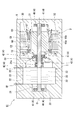
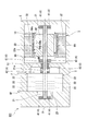
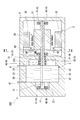
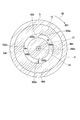
- FIG. 1 It is a mimetic diagram explaining the compressor system in a first embodiment of the present invention. It is a schematic diagram explaining the compressor system in the modification of 1st embodiment of this invention. It is a schematic diagram explaining the compressor system in 2nd embodiment of this invention. It is a schematic diagram explaining the compressor system in 3rd embodiment of this invention. It is sectional drawing containing the axis line which expands and shows the partition member in the compressor system in 3rd embodiment of this invention. It is a schematic diagram which shows the principal part of the compressor system in the modification of 3rd embodiment of this invention. It is a schematic diagram explaining the compressor system in 4th embodiment of this invention. FIG.
- FIG. 9 is a schematic diagram illustrating a compressor system according to a fourth embodiment of the present invention, and is a cross-sectional view taken along line A4-A4 of FIG. It is an expanded view which expands and shows the guide member in the compressor system in 4th embodiment of this invention. It is a schematic diagram explaining the compressor system in 5th embodiment of this invention.
- FIG. 10 is a cross-sectional view showing a main part of a compressor system according to a fifth embodiment of the present invention, and is a cross-sectional view taken along the line A5-A5 of FIG. It is a perspective view which shows the fluid introduction part of the compressor system in 5th embodiment of this invention.
- FIG. 10 is a cross-sectional view showing a main part of a compressor system according to a fifth embodiment of the present invention, and is a cross-sectional view taken along the line A5-A5 of FIG. It is a perspective view which shows the fluid introduction part of the compressor system in 5th embodiment of this invention.
- FIG. 10 is a cross-sectional view showing a main part of a compressor system according to a sixth embodiment of the present invention, which is a cross-sectional view corresponding to a cross section A5-A5 of FIG.
- FIG. 11 is a cross-sectional view showing a main part of a modified example of the fifth embodiment and the sixth embodiment of the present invention, and a cross-sectional view corresponding to the cross section A5-A5 of FIG. It is a schematic diagram explaining the compressor system in 7th embodiment of this invention.
- FIG. 16 is a schematic diagram illustrating a compressor system according to a seventh embodiment of the present invention, and is a cross-sectional view taken along line A7-A7 of FIG.
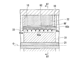
- FIG. 20 is a schematic diagram illustrating a compressor system according to a third modification of the seventh embodiment of the present invention, and is a cross-sectional view taken along line B7-B7 of FIG.
- FIG. 16 is a schematic diagram illustrating a compressor system according to an eighth embodiment of the present invention, which is a cross-sectional view corresponding to a cross section taken along line A7-A7 of FIG. It is a schematic diagram explaining the principal part of the compressor system in 9th embodiment of this invention. It is a schematic diagram explaining the principal part of the compressor system in the modification of 9th embodiment of this invention.
- the compressor system 1 is used in a submarine production system (Subsea Production System), which is one of the development methods of offshore oil and gas fields, and is installed on the seabed, or a floating production storage and offloading (FPSO). It is used in the sea and is provided at sea.
- the compressor system 1 pumps a production fluid (hereinafter simply referred to as a fluid F) such as oil and gas collected from a production well of an oil and gas field existing at several hundred to several thousand m in the seabed.
- a fluid F such as oil and gas collected from a production well of an oil and gas field existing at several hundred to several thousand m in the seabed.
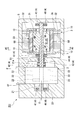
- the compressor system 1 includes a compressor 2 having a shaft 21 extending in the direction of an axis O (left and right direction in FIG. 1), a motor 3 having a rotor 31 directly connected to the shaft 21, and a shaft 21.
- positioned at the outer peripheral side of the rotor 31 are provided.
- the compressor 2 is accommodated in the casing 5, and the shaft 21 rotates around the axis O together with the rotor 31, thereby compressing the fluid F and generating a compressed fluid CF.
- the compressor 2 of this embodiment includes a shaft 21 extending in the direction of the axis O, an impeller 22 fixed to the shaft 21, and a housing 23 that houses the impeller 22.
- the shaft 21 is a rotating shaft extending in the direction of the axis O, and is supported by the casing 5 so as to be rotatable around the axis O.
- the shaft 21 passes through the housing 23, and both ends extend from the housing 23.
- the shaft 21 extends in the direction of the axis O in the casing 5 described later.
- the impeller 22 rotates together with the shaft 21 and compresses the fluid F passing through the impeller 22 to generate a compressed fluid CF.
- the housing 23 is an exterior part of the compressor 2 and houses the impeller 22 therein. The housing 23 is accommodated in the casing 5.
- the motor 3 is accommodated in the casing 5 with an interval in the direction of the axis O with respect to the compressor 2.
- the motor 3 includes a rotor 31 fixed so as to be integrated with the shaft 21 and a stator 32 disposed on the outer peripheral side of the rotor 31.
- the rotor 31 is integrated with the shaft 21 so as to be rotatable around the axis O.
- the rotor 31 is directly fixed to the outer peripheral side of the shaft 21 so as to rotate integrally with the shaft 21 of the compressor 2 without using a gear or the like.
- the rotor 31 has a rotor core (not shown) through which an induced current flows when the stator 32 generates a rotating magnetic field.
- the stator 32 is provided with an annular gap 33 centered on the axis O with respect to the rotor 31 in the radial direction so as to cover the rotor 31 from the outer peripheral side.
- the stator 32 has a plurality of stator cores (not shown) arranged along the circumferential direction of the rotor 31, and a stator winding (not shown) wound around the stator core.
- the stator 32 rotates the rotor 31 by generating a rotating magnetic field when an electric current flows from the outside.
- the stator 32 is fixed to the casing 5 in the casing 5.
- the bearing part 4 is accommodated in the casing 5 and supports the shaft 21 rotatably.
- the bearing portion 4 of this embodiment includes a plurality of journal bearings 41 and thrust bearings 42.
- the journal bearing 41 supports a load acting on the shaft 21 in the radial direction.
- the journal bearings 41 are arranged at both ends of the shaft 21 in the direction of the axis O so as to sandwich the motor 3 and the compressor 2 from the direction of the axis O.
- the journal bearing 41 is disposed between the area where the compressor 2 is provided and the area where the motor 3 is provided, and is also arranged closer to the motor 3 than a seal member 51 described later.
- the thrust bearing 42 supports a load acting on the shaft 21 in the direction of the axis O via a thrust collar 21 a formed on the shaft 21.
- the thrust bearing 42 is disposed between the area where the compressor 2 is provided and the area where the motor 3 is provided, and is disposed closer to the compressor 2 than a seal member 51 described later.
- Casing 5 accommodates compressor 2 and motor 3 inside.
- the casing 5 has a cylindrical shape along the axis O.
- the inner surface of the casing 5 protrudes toward the shaft 21 between the compressor 2 and the motor 3 in the direction of the axis O.
- the protruding portion is provided with a seal member 51 that seals between a region where the compressor 2 is provided and a region where the motor 3 is provided.
- the partition member 6 is disposed in an annular gap 33 between the rotor 31 and the stator 32, and is provided in a non-contact state between the rotor 31 and the stator 32.
- the partition member 6 has a cylindrical shape centered on the axis O, and is outward from one side (side closer to the compressor 2) of the axis O toward the other side (side away from the compressor 2). It has a shape in which the diameter and inner diameter are gradually reduced.
- the inner diameter of the partition member 6 decreases linearly toward the other side of the axis O. That is, the inner surface (surface) 6 a facing the radially inner side of the partition member 6 is linearly inclined from one side of the axis O toward the other side on the cross section including the axis O.
- the length dimension of the partition member 6 in the direction of the axis O is substantially the same as the length dimension in the direction of the axis O of the region where the rotor 31 and the stator 32 face each other in the radial direction.
- a partition member 6 is provided in the facing region.
- the wall thickness dimension of the partition member 6 is constant, and similarly, the outer diameter dimension of the partition member 6 decreases linearly toward the other side of the axis O. That is, the outer surface (surface) 6 b facing the radially outer side of the partition member 6 is linearly inclined from one side of the axis O toward the other side on the cross section including the axis O.
- the partition member 6 can be made of various materials such as organic materials such as metal, ceramics, and resin.
- the partition member 6 is fixed to the casing 5 so as not to rotate relative to the stator 32.
- the casing 5 is provided with support members 10 that protrude inward in the radial direction so as to face the direction of the axis O on both end surfaces facing the direction of the axis O of the stator 32.
- the partition member 6 is fixed.
- the support member 10 may have an annular shape centering on the axis O, may have a columnar shape protruding radially inward at a part of the circumferential direction, and the shape is not limited.
- the partition member 6 partitions the gap 33 in the radial direction and forms two spaces with the rotor 31. These two spaces are a rotor-side channel C1 between the partition member 6 and the rotor 31 and a stator-side channel C2 between the partition member 6 and the stator 32.
- a part of the compressed fluid CF from the compressor 2 leaks from the seal member 51 and flows into the rotor side channel C1 as a cooling fluid.
- This leakage flow LF is caused to flow into the rotor side flow path C1 by, for example, a fluid introduction portion (not shown).
- the fluid introduction part is, for example, a guide plate or a pipe provided in the casing 5 so as to guide the leakage flow LF that flows out from the seal member 51 to the motor 3 side.
- the partition member 6 moves in the direction in which the leakage flow LF flows along the rotor-side flow path C1 along the axis O, that is, from one side in the direction of the axis O. As it goes to the other side, it has an inner surface 6a in which the flow passage area in the cross section perpendicular to the axis O in the rotor side flow passage C1 gradually decreases.
- the temperature of the leakage flow LF that has exchanged heat with the rotor 31 increases toward the downstream side in the flow direction of the leakage flow LF.
- the flow path cross-sectional area in the cross section orthogonal to the axis O in the rotor side flow path C1 is reduced in the flow direction of the leakage flow LF by providing the partition member 6. To go.
- the flow rate of the leakage flow LF can be increased toward the downstream side, and the heat transfer rate can be improved.
- the heat exchange with the rotor 31 can be sufficiently performed even by the leakage flow LF whose temperature has increased on the downstream side. That is, the rotor 31 can be cooled more uniformly in the direction of the axis O by the leakage flow LF. As a result, the motor 3 can be efficiently cooled.
- the leakage flow LF from the compressor 2 is positively used as the cooling fluid, so that it is not necessary to separately introduce the cooling fluid into the rotor side channel C1. Therefore, it is not necessary to newly provide a structure for introducing such a cooling fluid, leading to cost reduction.
- the partition member 6 has a cylindrical shape in which the inner diameter dimension decreases toward the other side in the direction of the axis O, so that the flow path cross-sectional area decreases in the flow direction of the leakage flow LF.
- the rotor side channel C1 can be easily formed. Therefore, the flow rate of the leakage flow LF can be increased toward the downstream side, and the heat transfer rate can be improved.
- the leakage flow LF may flow into the stator side channel C2 from the other side of the axis O.
- the introduction flow path etc. which are formed in the inside of the casing 5, for example, and can guide the leakage flow LF toward the other side of the direction of the axis O are used.
- the support member 10 is opened to the stator side flow path C2 so that the leakage flow LF can flow into the stator side flow path C2 and can flow out of the stator side flow path C2.
- a through hole (not shown) penetrating in the direction of the axis O is formed.
- a columnar member provided in a part in the circumferential direction is used as the support member 10.
- the cylindrical partition member 6 whose outer diameter is reduced toward the other side in the direction of the axis O is provided, and the stator side flow path C2 leaks from the other side of the axis O.
- Flow LF is introduced. Therefore, in addition to the rotor-side channel C1, the stator-side channel C2 can also increase the flow rate of the leakage flow LF toward the downstream side, thereby improving the heat transfer coefficient. Therefore, the stator 32 can be cooled more uniformly in the direction of the axis O.
- both the inner diameter dimension and the outer diameter dimension of the partition member 6 are configured to become smaller toward the other side in the direction of the axis O.
- the inner diameter dimension and the outer diameter It may be formed so that at least one of the dimensions becomes smaller toward the other side in the direction of the axis O.
- the partition member 66 has a cylindrical shape centering on the axis O, and has a shape in which the radial thickness increases from one side of the axis O toward the other side.
- the inner surface 66 a facing the radially inner side and the outer surface 66 b facing the radially outer side of the partition member 66 are linearly inclined from one side of the axis O toward the other side on the cross section including the axis O.
- the support member 10 includes the stator-side flow path C2 so that the leakage flow LF can flow into the stator-side flow path C2 and out of the stator-side flow path C2.
- a through hole (not shown) penetrating in the direction of the axis O is formed so as to open.
- a columnar member provided in a part in the circumferential direction is used as the support member 10.
- the partition member 66 has a cylindrical shape in which the radial thickness increases toward the other side in the direction of the axis O, thereby allowing the leakage flow LF to flow.
- the rotor side flow path C1 and the stator side flow path C2 can be easily formed so that the flow path cross-sectional area becomes smaller in the direction.
- the flow rate of the leakage flow LF can be increased toward the downstream side, and the heat transfer rate can be improved. For this reason, even the leakage flow LF having a high temperature on the downstream side can sufficiently exchange heat, and the rotor 31 and the stator 32 can be cooled more uniformly in the direction of the axis O.
- the fluid introduction part does not necessarily have to be provided. That is, the leakage flow LF from the seal member 51 may naturally flow into one side in the direction of the axis O.
- the support member 10 is not limited to the above case. That is, it is only necessary that the partition member 6 (66) can be held in the gap 33 between the rotor 31 and the stator 32.
- leakage flow LF may be circulated only in the stator side channel C2.
- a cooling medium introduced from the outside or a bleed air from the compressor 2 may be used instead of the leakage flow LF in the rotor side flow path C1 and the stator side flow path C2.
- the partition member 6 (66) is not limited to the case where it is provided only in the facing region between the rotor 31 and the stator 32, and the dimension in the direction of the axis O may be smaller or larger. Good.
- the inner surface 6a (66a) and the outer surface 6b (66b) of the partition member 6 (66) may be inclined in a curve from one side of the axis O toward the other side on the cross section including the axis O.
- a step or the like may be formed at a midway position in the direction of the axis O.
- the compressor system 101 supports the compressor 2 having the shaft 21 extending in the direction of the axis O (the left-right direction in the drawing), the motor 3 having the rotor 31 directly connected to the shaft 21, and the shaft 21. And a casing 5 that houses the motor 3 and the compressor 2, and a partition member (swivel imparting portion) 6 ⁇ / b> A disposed on the outer peripheral side of the rotor 31.
- the partition member 6 ⁇ / b> A is disposed in an annular gap 33 between the rotor 31 and the stator 32, and is provided in a non-contact state between the rotor 31 and the stator 32.
- the partition member 6A has a cylindrical shape with the axis O as the center.
- partition member 6A Various materials such as organic materials such as metals, ceramics, and resins can be used for the partition member 6A.
- the partition member 6 ⁇ / b> A is fixed to the casing 5 so as not to rotate relative to the stator 32.
- the casing 5 is provided with support members 10 that protrude radially inward so as to face the direction of the axis O on both end faces of the stator 32 facing the direction of the axis O.
- the partition member 6 ⁇ / b> A is fixed to the support member 10.
- the support member 10 may have an annular shape with the axis O as the center, or may have a columnar shape protruding radially inward at a part of the circumferential direction, and the shape is not limited.
- the cooling fluid RF can be circulated in the gap 33a between the partition member 6A and the rotor 31.
- the cooling fluid RF includes, for example, a leakage flow in which a part of the compressed fluid CF from the compressor 2 leaks from the seal member 51, a cooling medium introduced from the outside of the casing 5, and from the compressor 2. Extraction or the like can be used.
- the cooling fluid RF flows into the gap 33 a from the compressor 2 side, which is one side in the direction of the axis O, by a flow path, a guide plate, and the like (not shown) provided in the casing 5.
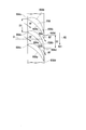
- the partition member 6A has an inner surface (surface) 6Aa that faces the rotor 31 and is recessed radially outward, and further toward the downstream side in the flow direction of the cooling fluid RF.
- a recess 6Ab having a spiral groove shape extending toward the front RD1 in the rotation direction RD is formed.
- the partition member 6A imparts the swirl component toward the front RD1 in the rotational direction RD to the cooling fluid RF that flows between the rotor 31 and the stator 32.
- the flow direction of the cooling fluid RF can be aligned with the direction in which the outer surface of the rotating rotor 31 advances.
- the cooling efficiency of the rotor 31 can be improved and the motor can be efficiently cooled.
- the dimension of the width W in the direction of the axis O in the recess 6Ab may be smaller on the downstream side than on the upstream side.
- the speed component in the rotational direction RD (circumferential direction) on the downstream side can be increased. Therefore, the cooling fluid RF can be accelerated on the downstream side, and heat transfer on the downstream side can be improved. For this reason, the rotor 31 can be sufficiently cooled also on the downstream side by the cooling air RF heated by exchanging heat with the rotor 31 on the upstream side.
- the formation interval in the direction of the axis O of the recess 6Ab may be narrower on the downstream side than on the upstream side. That is, the recess 6Ab may extend further along the rotation direction RD on the downstream side.
- the formation interval in the direction of the axis O of the recess 6Ab is narrower on the downstream side, so that the cooling fluid RF can be further accelerated in the rotational direction RD (circumferential direction) on the downstream side, and the downstream side The heat transfer at can be further improved.
- the recess 6Ab is formed in the partition member 6A, a spiral convex portion protruding inward in the radial direction from the inner surface 6Aa may be formed instead of the recess 6Ab.
- the partition member 6A is not limited to a cylindrical shape, and may be a member divided into a plurality in the circumferential direction. That is, the partition member 6 ⁇ / b> A may be a member having an inner surface 6 ⁇ / b> Aa that curves along the outer surface of the rotor 31.
- the recess 6Ab may be formed discontinuously without being continuous in the direction of the axis O.
- the compressor system 161 according to the second embodiment will be described with reference to FIGS.
- the same components as those in the third embodiment are denoted by the same reference numerals, and detailed description thereof is omitted.
- the compressor system 161 of the fourth embodiment is different in that it includes a guide member (turning imparting portion) 66A instead of the partition member 6A of the third embodiment.
- the guide member 66 is located upstream in the flow direction of the cooling fluid RF (in the direction of the axis O) from the inlet IN of the cooling fluid RF in the gap 33 between the rotor 31 and the stator 32.
- the inflow port IN indicates a region upstream of the opening (inlet) on the upstream side of the gap 33.
- a plurality of the guide members 66 ⁇ / b> A are fixed to the support member 10 so as to protrude radially inward from the support member 10 at intervals in the rotational direction RD. Thus, it is provided so as not to rotate relative to the stator 32.
- each guide member 66 ⁇ / b> A is formed to curve toward the front RD ⁇ b> 1 in the rotational direction RD as it goes downstream in the flow direction of the cooling fluid RF that is the other side in the direction of the axis O.
- the guide member 66A faces the upstream side and, as it goes toward the downstream side, the guide surface 66Aa that curves and inclines forward RD1 in the rotational direction RD with respect to the axis O, faces the downstream side, and downstream A back surface 66Ab that curves and inclines forward RD1 in the rotational direction RD with respect to the axis O as it goes to the side.
- the guide surface 66Aa of one guide member 66A and the back surface 66Ab of the other guide member 66A are opposed to the rotation direction RD (circumferential direction).
- the guide member 66A has a wing shape in cross section perpendicular to the radial direction by the guide surface 66Aa and the back surface 66Ab.
- the upstream end of the guide member 66A is a front edge 66Ac
- the downstream end is a rear edge 66Ad.
- the rotational direction RD (circumferential direction) between the rear edges 66Ad of the guide member 66A is larger than the dimension of the gap S1 in the rotational direction RD (circumferential direction) of the front edges 66Ac of the guide member 66A adjacent to the rotational direction RD. ) Of the gap S2 is smaller.
- the cooling fluid RF can be guided by the guide surface 66Aa by providing the guide member 66A having the guide surface 66Aa.
- the swirl component toward the front RD1 in the rotation direction RD is given to the cooling fluid RF toward the downstream side.
- the flow direction of the cooling fluid RF can be aligned with the direction in which the outer surface of the rotating rotor 31 advances. Therefore, the amount of heat generated by shearing caused by the rapid acceleration of the cooling fluid RF when the cooling fluid RF comes into contact with the outer surface of the rotor 31 can be suppressed. As a result, the cooling efficiency of the rotor 31 can be improved and the motor 3 can be efficiently cooled.
- the gap between the rear edges 66Ad is smaller than the gap between the front edges 66Ac of the guide member 66A. Therefore, when the cooling fluid RF guided by the guide surface 66Aa flows out from between the trailing edges 66Ad of the guide member 66A toward the gap 33 formed between the rotor 31 and the stator 32, the guide The flow velocity can be increased as compared with the case where the flow cooling fluid RF flows between the front edges 66Ac of the member 66A.
- the flow path area of the cooling fluid RF can be reduced on the trailing edge 66Ad side. Therefore, the cooling fluid RF can be accelerated in the rotation direction RD, and the cooling fluid RF can be accelerated in the rotation direction RD on the downstream side, so that heat transfer on the downstream side can be improved. For this reason, even with the cooling air RF heated by heat exchange with the rotor 31 on the upstream side, the rotor 31 can be sufficiently cooled also on the downstream side, and the cooling efficiency of the rotor 31 can be further improved. .
- the guide member 66A may be a simple flat plate having a rectangular cross section.
- the guide surface 66Aa is not limited to be formed to be curved, and has a planar shape that faces the upstream side and inclines toward the front side in the rotational direction RD with respect to the axis O as it goes downstream. May be. The same applies to the back surface 66Ab.
- gap S1 between the front edges 66Ac and the gap S2 between the rear edges 66Ad may have the same dimensions.
- the guide member 66A is not limited to the case where the guide member 66A is provided at the inflow port IN.
- the guide member 66A may be disposed in the gap 33 between the rotor 31 and the stator 32.
- a cylindrical member similar to the partition member 6A of the third embodiment may be provided, and the guide member 66A may be provided on the inner surface of the cylindrical member facing the rotor 31 side.
- the partition member 6A of the third embodiment and the guide member 66A of the fourth embodiment may be used in combination.
- cooling fluid RF may be circulated between the stator 32 and the partition member 6A.
- the partition member 6 ⁇ / b> B is disposed in an annular gap 33 between the rotor 31 and the stator 32, and is provided in a non-contact state with the rotor 31 and the stator 32.
- the partition member 6 ⁇ / b> B is fixed to the casing 5 so as not to rotate relative to the stator 32.
- a support member 10 is provided on the casing 5 so as to protrude radially inward on both sides in the direction of the axis O of the stator 32, and a partition member 6 ⁇ / b> B is fixed to the support member 10.
- the support member 10 may have an annular shape with the axis O as the center, or may have a columnar shape protruding radially inward at a part of the circumferential direction, and the shape is not limited.
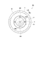
- the partition member 6 ⁇ / b> B extends so as to protrude radially inward from the support member 10 so as to divide the gap 33 into a plurality of spaces R in the circumferential direction, and the gap 33. It has a flat plate shape extending over the entire region in the direction of the axis O.
- the partition members 6B are provided at two positions at positions 180 degrees apart in the circumferential direction.
- the gap 33 is partitioned into two spaces R1 and R2.
- partition member 6B Various materials such as organic materials such as metals, ceramics, and resins can be used for the partition member 6B.
- the cooling fluid RF can flow along the direction of the axis O.
- the cooling fluid RF is, for example, a leakage flow in which a part of the compressed fluid CF from the compressor 2 leaks from the seal member 51, a cooling medium introduced from the outside of the casing 5, or a bleed air from the compressor 2. Can be used.
- the fluid introduction part 7 can flow in the cooling fluid RF from different sides of the direction of the axis O in the space R1 and the space R2. That is, the cooling fluid RF flows into the space R1 from the compressor 2 side that is one side in the direction of the axis O, and the cooling fluid RF flows into the space R2 from the other side in the direction of the axis O.
- the fluid introduction portion 7 is a manifold provided integrally with the support member 10, for example. That is, the curved flow path portion 8 having a semicircular shape covering the opening (inflow port R1a) on one side in the direction of the axis O in the space R1, and the middle position of the curved flow path portion 8 (just the central portion in the circumferential direction) And a projecting flow path portion 9 projecting outward in the radial direction.
- the curved flow path portion 8 is formed with a curved flow path 8a that opens over substantially the entire circumferential direction of the surface facing the inflow port R1a.
- the protruding flow path portion 9 is formed with a protruding flow path 9a that communicates with the curved flow path portion 8 and opens radially outward.
- the cooling fluid RF is introduced into the protruding channel 9a, and the cooling fluid RF can flow into the space R1 from the inlet R1a through the curved channel 8a.
- the curved flow path portion 8 that similarly covers the opening on the other side in the direction of the axis O in the space R1 (outlet R1b) on the other side in the direction of the axis O in the partition member 6B;
- a fluid outlet 7A having the same shape as the fluid inlet 7 having a projecting channel 9 projecting radially outward from a midway position (just the center in the circumferential direction) of the curved channel 8 is provided.
- the fluid lead-out part 7A allows the cooling fluid RF after flowing through the space R1 to flow out of the protruding flow path part 9.
- the fluid introduction part 7 is provided so as to cover the inflow port R2a which is the other side opening in the direction of the axis O in the space R2, and the outflow port R2b which is an opening on the one side in the direction of the axis O in the space R2.
- a fluid outlet 7A is provided to cover the fluid.
- Cooling fluid RF flows in from different directions. Accordingly, in these spaces R1 and R2, the cooling fluid RF flows in opposite directions.
- the cooling fluid RF flows through the gap 33 while exchanging heat with the rotor 31, the temperature of the cooling fluid RF on the downstream side in each of the spaces R1 and R2 is higher than the temperature on the upstream side. It is hot.
- the flow direction of the cooling fluid RF is opposite in the plurality of spaces R1 and R2 arranged in the circumferential direction, and the rotor 31 rotates relative to the plurality of spaces R1 and R2. Yes.
- the cooling fluid RF having a high temperature and the cooling fluid RF having a low temperature come into contact with the outer surface of the rotor 31 alternately. For this reason, even if the cooling fluid RF becomes high temperature on the downstream side of the spaces R1 and R2, it is possible to avoid that the high-temperature cooling fluid RF always comes into contact with the rotor 31 at the same position. . Therefore, the rotor 31 can be efficiently cooled over the direction of the axis O, and the motor 3 can be efficiently cooled.
- the partition member 66B is provided to be inclined with respect to the axis O. More specifically, the partition member 66B has a flat plate shape, and the end surface facing the inlet R1a (R2a) extends in the radial direction and extends in the circumferential direction toward the downstream side in the flow direction of the cooling fluid RF. Extends in the direction of rotation RD toward one RD1. That is, the partition member 66B has a guide surface 66Ba that faces the upstream side in the flow direction of the cooling fluid RF and tilts forward RD1 in the rotational direction RD of the rotor 31 with respect to the axis O as it goes downstream. ing.
- the cooling fluid RF is guided to the cooling fluid RF toward the downstream side by guiding the cooling fluid RF in the spaces R1 and R2 by the guide surface 66Ba of the partition member 66B.
- a turning component toward the front RD1 in the rotation direction RD is given. Therefore, the cooling fluid RF can be circulated along the direction in which the cooling fluid RF flows along the direction in which the outer surface of the rotating rotor 31 advances. Therefore, when the cooling fluid RF comes into contact with the outer surface of the rotor 31, the amount of heat generated by shearing generated by the rapid acceleration of the cooling fluid RF can be suppressed, and the cooling efficiency of the rotor 31 can be improved.
- the partition member 66B1 moves to the front RD1 in the rotational direction RD of the rotor 31, for example, toward the downstream side in the flow direction of the cooling fluid RF.
- It may be a member having a spiral plate shape extending toward the surface.
- the spiral member it is possible to effectively impart a swirl component toward the front RD1 in the rotation direction RD toward the cooling fluid RF toward the downstream side.
- the calorific value by the shear which arises when the cooling fluid RF is accelerated rapidly can be suppressed, and the cooling efficiency of the rotor 31 can be improved.
- the partition members 6B, 66B, and 66B1 may be disposed at least in a region where the rotor 31 and the stator 32 face each other in the radial direction. Further, the partition members 6B, 66B, 66B1 may be directly fixed to the stator 32.
- the number of the partition members 6B, 66B, 66B1 is not limited to the above case, and at least two may be provided. Moreover, it may be provided at unequal intervals in the circumferential direction.
- the flow direction of the cooling fluid RF may be different between the spaces R adjacent in the circumferential direction, but is not limited thereto. That is, the flow direction of the cooling fluid RF may be different in at least two spaces.
- the flow path is cut off in a cross section orthogonal to the axis O of the spaces R1 and R2 from the upstream side toward the downstream side. It is possible to reduce the area.
- the flow velocity of the cooling fluid RF can be increased on the downstream side, heat exchange can be performed and heat transfer with the rotor 31 can be promoted even by the cooling fluid RF that has reached a higher temperature.
- heat exchange with the rotor 31 can be effectively performed.
- the compressor system 301 includes a fluid supply member 6C disposed on the outer peripheral side of the rotor 31 in place of the partition member 6 (6A, 66A, 6B, 66B, 66B1).
- the fluid supply member 6 ⁇ / b> C is disposed in an annular gap 33 between the rotor 31 and the stator 32, and is provided in a non-contact state between the rotor 31 and the stator 32.
- the fluid supply member 6C has a cylindrical shape with the axis O as the center.
- the fluid supply member 6 ⁇ / b> C is fixed to the casing 5 so as not to rotate relative to the stator 32.
- the casing 5 is provided with the support member 10 so as to protrude radially inward so as to face the direction of the axis O at both end surfaces of the stator 32 facing the direction of the axis O, and supply fluid to the support member 10.
- the member 6C is fixed.
- the support member 10 may have an annular shape with the axis O as the center, or may have a columnar shape protruding radially inward at a part of the circumferential direction, and the shape is not limited.
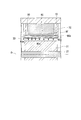
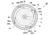
- the fluid supply member 6 ⁇ / b> C is formed with a plurality of ejection ports 6 ⁇ / b> Ca that are open toward the rotor 31 and can eject the cooling fluid RF at intervals in the direction of the axis O. Further, as shown in FIG. 16, a plurality of jet nozzles 6Ca are formed at intervals also in the circumferential direction. In the present embodiment, the ejection port 6Ca can eject the cooling fluid RF straightly inward in the radial direction. Further, when the fluid supply member 6C is viewed from the inside in the radial direction, the jet ports 6Ca may be arranged in a staggered manner or in a lattice shape.
- the fluid supply member 6C communicates with a plurality of jets 6Ca arranged in the direction of the axis O so that the cooling fluid RF from the outside can flow along the axis O, and the communication hole 6Cb extends in the direction of the axis O. Is further formed.
- a cooling fluid RF is supplied to the communication hole 6Cb through a fluid supply flow path (not shown) provided in the casing 5, and is further supplied to the jet outlet 6Ca through the communication hole 6Cb.
- the cooling fluid RF various fluids such as a leakage flow that is a part of the compressed fluid CF leaked from the seal member 51 to the motor 3 side, a cooling medium introduced from the outside, and bleed air from the compressor 2 are used. Can be used.
- the cooling fluid RF flows into the communication hole 6Cb from the compressor 2 side which is one side in the direction of the axis O.
- the compressor system 301 of the present embodiment described above by separately providing the fluid supply member 6C in which the jet outlet 6Ca is formed, before heat exchange with the rotor 31 from the outside of the casing 5,
- the cooling fluid RF having a lower temperature can always be supplied to the jet outlet 6Ca through the communication hole 6Cb.
- the low-temperature cooling fluid RF can always be ejected from the ejection port 6Ca to the rotor.
- the cooling efficiency of the rotor 31 can be improved and the motor can be efficiently cooled.
- the cooling fluid RF can be ejected evenly over the outer surface of the rotor 31 in the direction of the axis O. it can. Therefore, the cooling efficiency of the rotor 31 can be further improved.
- the communication hole 6 ⁇ / b> Cb is not formed in the fluid supply member 6 ⁇ / b> C, and the jet outlet 6 ⁇ / b> Ca is formed so that the jet outlet 6 ⁇ / b> Ca penetrates the fluid supply member 6 ⁇ / b> C in the radial direction. May be.
- the cooling fluid RF can be ejected from the ejection port 6Ca toward the rotor 31 by supplying the cooling fluid RF to the gap 33a1 formed between the stator 32 and the fluid supply member 6C.
- the jet outlet 6Ca located on the downstream side in the flow direction of the cooling fluid RF flowing through the communication hole 6Cb (the other side in the direction of the axis O) is upstream.
- the opening diameter may be larger than the jet outlet 6Ca located on the side.
- the cooling fluid RF flows through the communication hole 6Cb, the pressure loss increases toward the downstream side in the flow direction. Since the opening diameter of the jet outlet 6Ca is larger on the downstream side, a cooling fluid RF having a sufficient flow rate can be ejected toward the rotor 31 even on the downstream side regardless of such pressure loss. . Therefore, the cooling efficiency of the rotor 31 can be further improved.
- the jet outlet 6Ca located in the downstream of the distribution direction of the cooling fluid RF which distribute
- the cooling fluid RF having a sufficient flow rate can be ejected toward the rotor 31 even on the downstream side where the pressure loss increases. Therefore, the cooling efficiency of the rotor 31 can be further improved.
- the plurality of ejection ports 66Ca in the fluid supply member 66C communicate with the communication hole 66Cb, and are formed so that the cooling fluid RF can be ejected toward the front RD1 side in the rotational direction RD of the rotor 31. . That is, the spout 66Ca is formed so that an extension line of the central axis O2 of the spout 66Ca passes through the rotor 31.
- the cooling fluid RF ejected from the ejection port 66Ca is ejected toward the front RD1 in the rotational direction RD, thereby cooling in the direction in which the outer surface of the rotating rotor 31 advances. It is possible to follow the flow direction of the working fluid RF. As a result, when the cooling fluid RF comes into contact with the outer surface of the rotor 31, the amount of heat generated by shearing caused by the rapid acceleration of the cooling fluid RF can be suppressed. Therefore, the cooling efficiency of the rotor 31 can be further improved.
- the fluid supply member 76 is divided into two in the direction of the axis O. That is, the compressor system 371 is provided with a first fluid supply member 76A on one side in the direction of the axis O and a second fluid supply member 76B on the other side in the direction of the axis O.
- the first fluid supply member 76A and the second fluid supply member 76B each have a cylindrical shape centered on the axis O.
- the first fluid supply member 76 ⁇ / b> A and the second fluid supply member 76 ⁇ / b> B are provided with a gap in the direction of the axis O, and each is fixed to the casing 5 by the support member 10.
- the first fluid supply member 76A is supplied with cooling fluid RF from one side in the direction of the axis O to the communication hole 76b, and the second fluid supply member 76B is cooled from the other side in the direction of the axis O.
- the fluid RF is supplied to the communication hole 76b. Then, the cooling fluid RF is ejected from the ejection port 76 a toward the rotor 31.
- the cooler cooling fluid RF before heat exchange with the rotor 31 can always be supplied to the communication hole 76b and can be ejected from the ejection port 76a. Therefore, the cooling efficiency of the rotor 31 can be improved. As a result, the motor can be efficiently cooled.
- the plug 80 for closing the communication hole 6Cb may be provided, and the cooling fluid RF may be supplied to the communication hole 6Cb from both sides in the direction of the axis O. Also in this case, it is possible to always supply the cooling fluid RF having a lower temperature before the heat exchange with the rotor 31 to the ejection port 6Ca and eject the cooling fluid RF from the ejection port 6Ca. The cooling efficiency of 31 can be improved. As a result, the motor can be efficiently cooled.
- the number of communication holes 6Ca (66Ca, 76a) is not particularly limited, and only one may be formed.
- the jet outlet 6Ca (66Ca, 76a) is at least in the opposed region where the rotor 31 and the stator 32 face each other in the radial direction. It is good to be formed.
- the shape of the fluid supply member 6C (66C, 76) is not limited to the above case.
- it may be a flat member disposed in the gap 33.
- the support member 10 is not limited to the above case. That is, it is sufficient if the fluid supply member 6C (66C, 76) can be held in the gap 33 between the rotor 31 and the stator 32.
- the fluid supply member 6C (66C, 76) may be directly fixed to the stator 32.
- the motor can be efficiently cooled.
- Compressor system 2 Compressor 3 Motor 4 Bearing part 5 Casing 6 Partition members 6a inner surface 6b exterior 10 Support member 21 Shaft 22 Impeller 23 Housing 31 rotor 32 Stator 33 Clearance 41 Journal bearing 42 Thrust bearing 51 Sealing member F fluid CF compressed fluid LF Leakage flow C1 Rotor side flow path C2 Stator side flow path O axis 61 Compressor system 66 Partition members 66a inner surface 66b Outer surface 101, 161 Compressor system 6A Partition member (turning imparting portion) 6Aa Inner surface (surface) 6Ab Concave portion 33a Clearance RF Cooling fluid RD Rotation direction RD1 Front W width 66A Guide member (swivel imparting portion) IN inlet 66Aa Guide surface 66Ab Back surface 66Ac Front edge 66Ad Rear edge S1, S2 Clearance 201, 261 Compressor system 6B, 66B, 66B1 Partition member 7 Fluid introduction part 7A Fluid outlet part 8 Curved channel part 8a Cur
Landscapes
- Engineering & Computer Science (AREA)
- Power Engineering (AREA)
- Mechanical Engineering (AREA)
- General Engineering & Computer Science (AREA)
- Physics & Mathematics (AREA)
- Thermal Sciences (AREA)
- Structures Of Non-Positive Displacement Pumps (AREA)
- Motor Or Generator Cooling System (AREA)
Abstract
圧縮機システム(1)は、モータ(3)と、モータ(3)のロータ(31)とともに回転することで圧縮流体(CF)を生成する圧縮機(2)と、ロータ(31)とステータ(32)との間に形成された隙間(33)に配置されて隙間(33)を径方向に仕切るとともに、ロータ(31)との間に漏れ流れ(LF)が軸線(O)に沿って流通可能なロータ側流路(C1)、及び、ステータ(32)との間に漏れ流れ(LF)が軸線(O)に沿って流通可能なステータ側流路(C2)を形成する仕切り部材(6)と、を備えている。仕切り部材(6)は、漏れ流れ(LF)の流通する方向に向かうに従って、ロータ側流路(C1)及びステータ側流路(C2)のうち、少なくとも一方の流路における軸線(O)に直交する断面での流路面積が小さくなるような内面(6a)、外面(6b)を有している。
Description
本発明は、圧縮機システムに関する。
本願は、2015年3月18日に出願された特願2015-054570号、特願2015-055098号、特願2015-054983号、および、特願2015-055099号に基づき優先権を主張し、その内容をここに援用する。
本願は、2015年3月18日に出願された特願2015-054570号、特願2015-055098号、特願2015-054983号、および、特願2015-055099号に基づき優先権を主張し、その内容をここに援用する。
モータと圧縮機とが一体となっている圧縮機システムは、空気やガス等の気体を圧縮する圧縮機と、圧縮機を駆動させるモータとを有している。圧縮機システムでは、圧縮機のケーシングから延在する回転軸と、モータのケーシングから同様に延在するモータの回転軸とが接続され、モータの回転が圧縮機に伝達される。このモータ及び圧縮機の回転軸は、複数の軸受により支持されることで安定して回転する。
このような圧縮機システムは、例えば、非特許文献1のような海底生産システム(Subsea Production System)や、非特許文献2のような浮体式海洋石油貯蔵設備(Floating Production Storage and Offloading、FPSO)に使用される。海底生産システムに使用される際には、圧縮機システムは、海底に設置され、海底から数千mの深さまで掘削した生産井から原油や天然ガス等が混在した生産流体を海上に送り出している。また、浮体式海洋石油貯蔵設備に使用される際には、圧縮機システムは、船舶等の海上設備に設置されている。
三菱重工技報 Vol.34 No.5 P310-P313
Turbomachinery International September/October 2014 P18-P24
ところで、圧縮機システムのモータでは、ロータが高速で回転することで、ロータとステータとの間で発熱し、ロータやステータが高温となってしまう。ロータやステータが高温となると、モータの効率が低下してしまう可能性や、モータの寿命が短くなってしまう可能性があり、ロータやステータを冷却する必要がある。
しかしながら、ロータの軸線方向の一方から他方に向かってステータ内部やステータとロータとの隙間に冷却媒体を流通させてロータ及びステータを冷却する場合には、流通している途中で冷却媒体が温まってしまい、効率的にロータ及びステータを冷却することが難しい。
本発明は、モータを効率的に冷却することが可能な圧縮機システムを提供する。
本発明の第一の態様に係る圧縮機システムは、軸線回りに回転するロータと、前記ロータと隙間を空けて該ロータの外周側に配置されたステータとを有するモータと、前記ロータとともに回転することで圧縮流体を生成する圧縮機と、前記ロータと前記ステータとの間に形成された前記隙間に配置されて前記隙間を径方向に仕切るとともに、前記ロータとの間に冷却用流体が前記軸線に沿って流通可能なロータ側流路、及び、前記ステータとの間に前記軸線に沿って冷却用流体が流通可能なステータ側流路を形成する仕切り部材と、を備え、前記仕切り部材は、前記冷却用流体の流通する方向に向かうに従って、前記ロータ側流路及び前記ステータ側流路のうち、少なくとも一方の流路における前記軸線に直交する断面での流路面積が小さくなるような表面を有している。
ロータ、ステータとの間で熱交換を行った冷却用流体の温度は流通方向の下流側に向かって上昇していく。ここで、本態様の圧縮機システムによれば、仕切り部材を設けたことでロータ側流路及びステータ側流路のうちの少なくとも一方で、流路面積が冷却用流体の流通方向に小さくなっていく。この結果、下流側に向かって冷却用流体の流速を増大させることができ、熱伝達率を向上することができる。よって、下流側で温度が高くなった冷却用流体によってもロータ、ステータとの間で十分に熱交換を行うことができる。即ち、冷却用流体によって、ロータ、ステータを軸線の方向にわたって、より均一に冷却することが可能となる。
また、本発明の第二の態様に係る圧縮機システムでは、上記第一の態様における前記ロータ側流路及び前記ステータ側流路を流通する冷却用流体は、前記圧縮機からの圧縮流体の漏れ流れであってもよい。
圧縮機からは、圧縮流体の一部がシールを通過した漏れ流れが発生する。この漏れ流れを積極的に冷却用流体として用いることで、別途で冷却用流体をロータ側流路、ステータ側流路に導入する必要がなくなる。従って、このような冷却用流体を導入するための別途の構造を新たに設ける必要がなくなるため、コストの抑制につながる。
また、本発明の第三の態様に係る圧縮機システムでは、上記第一又は第二の態様における前記仕切り部材は、前記軸線を中心とした筒状をなし、かつ、前記軸線の一方側から他方側に向かって内径寸法が小さくなる形状をなし、前記冷却用流体は前記ロータ側流路へ前記軸線の一方側から流入してもよい。
このように、仕切り部材が、軸線の方向の他方側に向かって内径寸法が小さくなる筒状をなすことで、ロータ側流路の流路断面積を冷却用流体の流通方向に向かって小さくしていくことができる。従って、ロータ側流路では、下流側に向かって冷却用流体の流速を増大させることができ、熱伝達率を向上することができる。このため、下流側で温度の高くなった冷却用媒体によっても十分に熱交換が可能となり、ロータを軸線の方向にわたって、より均一に冷却することが可能となる。
また、本発明の第四の態様に係る圧縮機システムでは、上記第一から第三のいずれかの態様における前記仕切り部材は、前記軸線を中心とした筒状をなし、かつ、前記軸線の一方側から他方側に向かって外径寸法が小さくなる形状をなし、前記冷却用流体は前記ステータ側流路へ前記軸線の他方側から流入してもよい。
軸線の方向の他方側に向かって外径寸法が小さくなる筒状をなす仕切り部材によって形成されたステータ側流路に、軸線の他方側から冷却用流体を流入させることで、ステータ側流路でも下流側に向かって流路断面積を小さくしていくことができる。よって、冷却用流体の流速を下流側に向かって増大させていくことができ、熱伝達率を向上することができる。よってステータを軸線の方向にわたって、より均一に冷却することが可能となる。
また、本発明の第五の態様に係る圧縮機システムでは、上記第一又は第二の態様における前記仕切り部材は、前記軸線を中心とした筒状をなし、かつ、前記軸線の一方側から他方側に向かって前記ロータの径方向の肉厚寸法が大きくなる形状をなし、前記冷却用流体は前記ロータ側流路及び前記ステータ側流路へ前記軸線の一方側から流入してもよい。
このように、仕切り部材が、軸線の方向の他方側に向かって径方向の肉厚寸法が大きくなる筒状をなし、冷却用流体が軸線の方向の一方側から流入することで、ロータ側流路及びステータ側流路の両方で、下流側に向かって流路断面積を小さくしていくことができる。よって、ロータ側流路及びステータ側流路の両方で、冷却用流体の流速を下流側に向かって増大させていくことができ、熱伝達率を向上することができる。よってロータ及びステータを軸線の方向にわたって、より均一に冷却することが可能となる。
また、本発明の第六の態様に係る圧縮機システムでは、上記第一から第五のいずれかの態様における前記仕切り部材は、少なくとも前記ロータと前記ステータとが前記ロータの径方向に対向する領域に設けられていてもよい。
このような領域に仕切り部材が設けられることで、最も発熱量が大きくなるロータとステータとの対向領域で、冷却用流体によって効果的な冷却を行うことができる。
本発明の第七の態様に係る圧縮機システムは、軸線回りに回転するロータと、冷却用流体が前記軸線に沿って流通可能な隙間を前記ロータとの間に空けて該ロータの外周側に配置されたステータとを有するモータと、前記ロータとともに回転することで圧縮流体を生成する圧縮機と、前記ロータと前記ステータとの間に形成された前記隙間を流通する前記冷却用流体に前記ロータの回転方向の前方へ向かう旋回成分を付与する旋回付与部と、を備えている。
このような圧縮機システムによれば、ロータとステータとの間の隙間を流通する冷却用流体に対して、回転方向の前方に向かう旋回成分を旋回付与部によって付与することで、回転するロータの外面の進む方向に冷却用流体の流通方向を沿わせることができる。よって、冷却用流体がロータの外面と接触することで冷却用流体が急加速されて生じるせん断による発熱量を抑えることができ、ロータの冷却効率を向上できる。
また、本発明の第八の態様に係る圧縮機システムでは、上記第七の態様における前記旋回付与部は、前記ロータと前記ステータとの間の前記隙間に配置されて該隙間を径方向に仕切り、前記ロータとの間で前記冷却用流体を前記軸線に沿って流通可能とし、かつ、前記冷却用流体の流通方向の下流側に向かうに従って、前記ロータの回転方向の前方に向かって延びる凸部又は凹部が前記ロータ側を向く表面に形成された仕切り部材であってもよい。
このような仕切り部材を設けることで、仕切り部材とロータとの間を流通する冷却用流体が凸部又は凹部によって案内される。この結果、冷却用流体には、下流側に向かうに従って回転方向の前方に向かう旋回成分が付与される。従って、ロータの外面の進む方向に冷却用流体の流通方向を沿わせることができ、せん断による発熱量を抑えることができ、ロータの冷却効率を向上できる。
また、本発明の第九の態様に係る圧縮機システムでは、上記第八の態様における前記仕切り部材には前記凹部が形成され、前記凹部における前記軸線の方向の幅寸法は、前記冷却用流体の流通方向の上流側に比べて下流側で小さくなっていてもよい。
このように凹部の幅寸法を下流側で小さくすることで、下流側での回転方向(周方向)の速度成分を増大させることができる。従って、下流側で回転方向に冷却用流体を加速することができ、下流側での熱伝達を向上することができる。このため、上流側でロータとの間で熱交換を行って昇温した冷却用空気によっても、下流側でも十分にロータを冷却することができ、ロータの冷却効率をさらに向上できる。
また、本発明の第十の態様に係る圧縮機システムでは、上記第七の態様における前記旋回付与部は、前記ロータと前記ステータとの間の前記隙間における前記冷却用流体の流入口よりも前記流通方向の上流側に配置されて、前記ステータに対して相対回転不能に設けられた案内部材であり、前記案内部材は、前記冷却用流体の流通方向の上流側を向き、かつ、下流側に向かうに従って前記軸線に対して前記ロータの回転方向の前方に向かって傾斜する案内面を有していてもよい。
このような案内面を有する案内部材を設けることで、案内面によって冷却用流体を案内することができる。この結果、冷却用流体には、下流側に向かうに従って回転方向の前方に向かう旋回成分が付与される。従って、ロータの外面の進む方向に冷却用流体の流通方向を沿わせることができ、せん断による発熱量を抑えることができ、ロータの冷却効率を向上できる。
また、本発明の第十一の態様に係る圧縮機システムでは、上記第十の態様における前記案内部材は、前記ロータの回転方向に隙間をあけて複数設けられ、前記回転方向に隣接する前記案内部材における前縁同士の前記回転方向の隙間寸法よりも、前記案内部材における後縁同士の前記回転方向の隙間寸法の方が小さくなっていてもよい。
このように、案内部材における上流側の端部となる前縁同士の隙間寸法よりも、下流側の端部となる後縁同士の隙間寸法の方が小さくなっている。このため、案内面によって案内された冷却用流体が案内部材の後縁同士の間からロータとステータとの間に形成された隙間に向って流出する際には、案内部材の前縁同士の間に流入する際よりも流速が増大する。即ち、後縁側で冷却用流体の流路面積を小さくすることができる。従って、回転方向(周方向)の前方に冷却用流体を加速することができ、ロータの外面の進む方向に冷却用流体の流通方向を沿わせることができる。よって、せん断による発熱量を抑えることができ、ロータの冷却効率を向上できる。
本発明の第十二の態様に係る圧縮機システムは、軸線回りに回転するロータと、前記ロータと冷却用流体が前記軸線に沿って流通可能な隙間を空けて該ロータの外周側に配置されたステータとを有するモータと、前記ロータとともに回転することで圧縮流体を生成する圧縮機と、前記ステータから前記ロータに向かって延びるように前記ステータに対して相対回転不能に設けられ、前記ステータと前記ロータとの間に形成された前記隙間を周方向に複数の空間に区画する複数の仕切り部材と、前記複数の空間のうちの少なくとも二つの空間で、前記軸線の方向の互いに異なる側から、前記冷却用流体を流入可能とする流体導入部と、を備えている。
このような圧縮機システムによれば、仕切り部材によってロータとステータとの間の隙間を周方向に区画して形成された複数の空間の各々で、異なる側から冷却用空気が流入する。従って、これら空間には、軸線の方向に互いに反対方向に冷却用流体が流通する。冷却用流体は、ロータと熱交換を行いつつ流通するため、冷却用流体の流通方向の下流側での冷却用流体の温度は、上流側の温度に比べて高温となっている。しかしながら、周方向に並ぶ複数の空間同士で冷却用流体の流通方向が反対方向となっており、複数の空間に対してロータは相対回転しているため、例えば仕切り部材における軸線の方向の端部の位置(ある一つの空間における上流側及び下流側の位置)では、ロータには高温となった冷却用空気と低温の冷却用空気とが交互に接触することになる。従って、ある空間における下流側の位置で冷却用空気が高温となっても、この高温の冷却空気が常にロータの同じ位置に接触することがなくなり、軸線の方向にわたってロータを効率的に冷却することができる。
また、本発明の第十三の態様に係る圧縮機システムでは、上記第十二の態様における前記仕切り部材は板状をなし、前記冷却用流体の流通方向の上流側を向き、かつ、下流側に向かうに従って前記軸線に対して前記ロータの回転方向の前方に傾斜する案内面を有していてもよい。
このような案内面によって、冷却用流体を案内することで、冷却用流体には、下流側に向かうに従って回転方向の前方に向かう旋回成分が付与される。従って、回転するロータの外面の進む方向に冷却用流体の流通方向を沿うようにでき、冷却用流体がロータの外面と接触することで冷却用流体が急加速されて生じるせん断による発熱量を抑えることができる。従って、ロータの冷却効率を向上できる。
また、本発明の第十四の態様に係る圧縮機システムでは、上記第十三の態様における前記仕切り部材は前記冷却用流体の流通方向の下流側に向かうに従って前記ロータの回転方向の前方に向かって延びる螺旋板状をなす部材であり、前記案内面は、前記螺旋板状をなす部材における前記冷却用流体の流通方向の上流側を向く面であってもよい。
このように仕切り部材に螺旋板状をなす部材を用いることで、冷却用流体に下流側に向かうに従って回転方向の前方に向かう旋回成分を効果的に付与することができる。冷却用流体がロータの外面と接触することで冷却用流体が急加速されて生じるせん断による発熱量を抑えることができ、ロータの冷却効率を向上できる。
また、本発明の第十五の態様に係る圧縮機システムでは、上記第十二から十四のいずれかの態様における前記仕切り部材は、少なくとも前記ロータと前記ステータとが前記ロータの径方向に対向する領域に設けられていてもよい。
このような領域に仕切り部材が設けられることで、最も発熱量が大きくなるロータとステータとの対向領域で、冷却用流体によって効果的な冷却を行うことができる。
本発明の第十六の態様に係る圧縮機システムは、軸線回りに回転するロータと、前記ロータと隙間を空けて該ロータの外周側に配置されたステータとを有するモータと、前記ロータとともに回転することで圧縮流体を生成する圧縮機と、前記ロータと前記ステータとの間に形成された前記隙間に配置され、前記ステータに対して相対回転不能に設けられてロータの回転軸線の方向に延び、前記ロータに向かって開口して冷却用流体を噴出可能な噴出口が形成された流体供給部材と、を備えている。
このような圧縮機システムによれば、冷却用流体の噴出口が形成された流体供給部材を別途で設けることで、ロータとの間で熱交換を行う前の低温の冷却用流体を、常に噴出口に供給することができる。このため、噴出口からは常に低温の冷却用流体をロータに噴出することができ、ロータの冷却効率を向上できる。
また、本発明の第十七の態様に係る圧縮機システムでは、上記第十六の態様における前記流体供給部材における前記噴出口は、前記ロータの回転方向の前方側に向かって前記冷却用流体を噴射可能に形成されていてもよい。
ロータは回転しているため、噴出口からの冷却用流体をこのロータの回転方向の前方に向けて噴出することで、回転するロータの外面の進む方向に冷却用流体の流通方向を沿うようにできる。よって、冷却用流体がロータの外面と接触することで冷却用流体が急加速されて生じるせん断による発熱量を抑えることができる。従って、ロータの冷却効率を向上できる。
また、本発明の第十八の態様に係る圧縮機システムでは、上記第十六又は十七の態様における前記流体供給部材には、前記軸線の方向に間隔をあけて複数の前記噴出口が形成されているとともに、前記軸線の方向に延びてこれら複数の前記噴出口に連通して外部からの前記冷却用流体が前記軸線の一方側から流入可能な連通孔が形成されていてもよい。
このように連通孔を通じて軸線の方向に並ぶ複数の噴出口に冷却用流体を供給することで、ロータの外面に対して軸線の方向にわたってまんべんなく冷却用流体を噴出することができる。よって、ロータの冷却効率をさらに向上することができる。
また、本発明の第十九の態様に係る圧縮機システムにおける前記流体供給部材では、上記第十八の態様における前記連通孔を流通する前記冷却用流体の流通方向の下流側に位置する前記噴出口の方が、上流側に位置する前記噴出口に比べて開口径が大きくなっていてもよい。
冷却用流体が連通孔を流通する際には、下流に向かうにつれて圧力損失が大きくなる。ここで、下流側の方が噴出口の開口径が大きくなっていることで、下流側でも十分な流量の冷却用流体をロータへ向けて噴出することができる。よって、ロータの冷却効率をさらに向上することができる。
また、本発明の第二十の態様に係る圧縮機システムにおける前記流体供給部材では、上記第十八又は十九の態様における前記流体供給部材の前記噴出口は、前記軸線の方向及び前記ロータの周方向に間隔をあけて複数形成され、前記流体供給部材には、前記連通孔を流通する前記冷却用流体の流通方向の下流側に位置する前記噴出口の方が、上流側に位置する前記噴出口に比べて、前記周方向により多く形成されていてもよい。
このように下流側で噴出口の数量を多くすることで、圧力損失が大きくなる下流側で十分な流量の冷却用流体をロータへ向けて噴出することができる。よって、ロータの冷却効率をさらに向上することができる。
上記の圧縮機システムによれば、モータを効率的に冷却することができる。
<第一実施形態>
以下、本発明に係る第一実施形態について図1を参照して説明する。
圧縮機システム1は、海洋油ガス田開発方式の一つである海底生産システム(Subsea Production System)に使用されて海底に設けられたり、浮体式海洋石油貯蔵設備(Floating Production Storage and Offloading、FPSO)に使用されて海上に設けられたりする。圧縮機システム1は、海底数百から数千mに存在する油ガス田の生産井から採取された油・ガス等の生産流体(以下、単に流体Fとする)を圧送する。
以下、本発明に係る第一実施形態について図1を参照して説明する。
圧縮機システム1は、海洋油ガス田開発方式の一つである海底生産システム(Subsea Production System)に使用されて海底に設けられたり、浮体式海洋石油貯蔵設備(Floating Production Storage and Offloading、FPSO)に使用されて海上に設けられたりする。圧縮機システム1は、海底数百から数千mに存在する油ガス田の生産井から採取された油・ガス等の生産流体(以下、単に流体Fとする)を圧送する。
圧縮機システム1は、軸線Oの方向(図1の左右方向)に延在するシャフト21を有する圧縮機2と、シャフト21に直接的に接続されるロータ31を有するモータ3と、シャフト21を支持する軸受部4と、モータ3と圧縮機2とを収容するケーシング5と、ロータ31の外周側に配置された仕切り部材6とを備えている。
圧縮機2は、ケーシング5内に収容され、ロータ31とともにシャフト21が軸線O回りに回転することで流体Fを圧縮して圧縮流体CFを生成する。本実施形態の圧縮機2は、軸線Oの方向に延在するシャフト21と、シャフト21に固定されたインペラ22と、インペラ22を収容するハウジング23とを有している。
シャフト21は、軸線O方向に延在する回転軸であり、軸線O回りに回転可能にケーシング5に支持されている。シャフト21は、ハウジング23を貫通しており、両端がハウジング23から延出している。シャフト21は、後述するケーシング5内において軸線O方向に延在している。
インペラ22は、シャフト21とともに回転し、インペラ22内部を通過する流体Fを圧縮して圧縮流体CFを生成する。
ハウジング23は、圧縮機2の外装部品であり、インペラ22を内部に収容している。ハウジング23は、ケーシング5内に収容されている。
ハウジング23は、圧縮機2の外装部品であり、インペラ22を内部に収容している。ハウジング23は、ケーシング5内に収容されている。
モータ3は、圧縮機2に対して軸線Oの方向に間隔を空けてケーシング5内に収容されている。モータ3は、シャフト21と一体をなすように固定されたロータ31と、ロータ31の外周側に配置されるステータ32とを有している。
ロータ31は、シャフト21と一体となって軸線O回りに回転可能とされている。ロータ31は、圧縮機2のシャフト21に対してギア等を介さずに一体となって回転するように、シャフト21の外周側に直接固定されている。ロータ31は、ステータ32が回転磁界を生成することによって誘導電流が流れる回転子鉄心(不図示)を有している。
ステータ32は、ロータ31を外周側から覆うように、ロータ31に対して軸線Oを中心とした環状の隙間33を径方向に空けて設けられている。ステータ32は、ロータ31の周方向に沿って複数配置された固定子鉄心(不図示)と、固定子鉄心に巻回された固定子巻線(不図示)とを有している。ステータ32は、外部から電流が流れることで回転磁場を生成してロータ31を回転させる。ステータ32は、ケーシング5内でケーシング5に固定されている。
軸受部4は、ケーシング5に収容され、シャフト21を回転可能に支持する。本実施形態の軸受部4は、複数のジャーナル軸受41及びスラスト軸受42を備えている。
ジャーナル軸受41は、シャフト21に対して径方向に作用する荷重を支持する。ジャーナル軸受41は、軸線Oの方向からモータ3及び圧縮機2を挟み込むようにシャフト21における軸線Oの方向の両端に配置されている。ジャーナル軸受41は、圧縮機2が設けられた領域とモータ3が設けられた領域との間であって、後述するシール部材51よりもモータ3側にも配置されている。
スラスト軸受42は、シャフト21に形成されたスラストカラー21aを介して、シャフト21に対して軸線Oの方向に作用する荷重を支持する。スラスト軸受42は、圧縮機2が設けられた領域とモータ3が設けられた領域との間であって、後述するシール部材51よりも圧縮機2側に配置されている。
ケーシング5は、圧縮機2とモータ3とを内部に収容している。ケーシング5は、軸線Oに沿った円筒形状をなしている。ケーシング5の内面は、軸線O方向の圧縮機2とモータ3との間でシャフト21に向かって突出している。この突出した部分には、圧縮機2が設けられた領域とモータ3が設けられた領域との間をシールするシール部材51が設けられている。
仕切り部材6は、ロータ31とステータ32との間の環状の隙間33に配置されて、ロータ31とステータ32とに非接触の状態で設けられている。具体的には、仕切り部材6は軸線Oを中心とした筒状をなし、かつ、軸線Oの一方側(圧縮機2に近い側)から他方側(圧縮機2から離れる側)に向かって外径寸法及び内径寸法が漸次小さくなる形状をなしている。
本実施形態では、仕切り部材6の内径寸法は軸線Oの他方側に向かって一次関数的に減少する。即ち、仕切り部材6における径方向内側を向く内面(表面)6aは、軸線Oを含む断面上で、軸線Oの一方側から他方側に向かって直線的に傾斜している。また、仕切り部材6の軸線Oの方向の長さ寸法は、ロータ31とステータ32とが径方向に対向する領域の軸線Oの方向の長さ寸法と略同じ寸法となっている。この対向領域に仕切り部材6が設けられている。
仕切り部材6の肉厚寸法は一定であり、同様に、仕切り部材6の外径寸法は軸線Oの他方側に向かって一次関数的に減少する。即ち、仕切り部材6における径方向外側を向く外面(表面)6bは、軸線Oを含む断面上で、軸線Oの一方側から他方側に向かって直線的に傾斜している。
仕切り部材6には、例えば金属、セラミックス、樹脂等の有機材料等、様々な材料を用いることができる。
仕切り部材6は、ステータ32に対して相対回転不能となるように、ケーシング5に固定されている。例えば、ケーシング5には、ステータ32の軸線Oの方向を向く両端面に軸線Oの方向に対向するように径方向内側に突出する支持部材10が設けられ、この支持部材10の径方向内側に仕切り部材6が固定されている。
支持部材10は、軸線Oを中心とした環状をなしてもよいし、周方向の一部で径方向内側に突出する柱状をなしてもよく、また、形状は限定されない。
支持部材10は、軸線Oを中心とした環状をなしてもよいし、周方向の一部で径方向内側に突出する柱状をなしてもよく、また、形状は限定されない。
また、この仕切り部材6は、隙間33を径方向に仕切るとともに、ロータ31との間に二つの空間を形成している。これら二つの空間は、仕切り部材6とロータ31との間のロータ側流路C1、及び、仕切り部材6とステータ32との間のステータ側流路C2である。
ここで、本実施形態の圧縮機システム1では、圧縮機2からの圧縮流体CFのうちの一部がシール部材51から漏れ出た漏れ流れLFを冷却用流体として、ロータ側流路C1に流入させる。
この漏れ流れLFは、例えば不図示の流体導入部によってロータ側流路C1に流入させられる。この流体導入部は、例えばシール部材51からモータ3側に流出した漏れ流れLFを案内するように、ケーシング5内に設けられた案内板や管路等である。
この漏れ流れLFは、例えば不図示の流体導入部によってロータ側流路C1に流入させられる。この流体導入部は、例えばシール部材51からモータ3側に流出した漏れ流れLFを案内するように、ケーシング5内に設けられた案内板や管路等である。
以上説明した本実施形態の圧縮機システム1では、仕切り部材6は、漏れ流れLFがロータ側流路C1を軸線Oに沿って流通する方向に向かうに従って、即ち、軸線Oの方向の一方側から他方側に向かうに従って、ロータ側流路C1における軸線Oに直交する断面での流路面積が漸次小さくなるような内面6aを有している。
従って、ロータ31との間で熱交換を行った漏れ流れLFの温度は、漏れ流れLFの流通方向の下流側に向かって上昇していく。ここで、本実施形態の圧縮機システム1では、仕切り部材6を設けたことでロータ側流路C1における軸線Oに直交する断面での流路断面積は、漏れ流れLFの流通方向に小さくなっていく。この結果、下流側に向かって漏れ流れLFの流速を増大させることができ、熱伝達率を向上することができる。
よって、下流側で温度が高くなった漏れ流れLFによっても、ロータ31との間で十分に熱交換を行うことができる。即ち、漏れ流れLFによって、ロータ31を軸線Oの方向にわたって、より均一に冷却することが可能となる。その結果、モータ3を効率的に冷却することができる。
さらに、圧縮機2からの漏れ流れLFを積極的に冷却用流体として用いることで、別途で冷却用流体をロータ側流路C1に導入する必要がなくなる。従って、このような冷却用流体を導入する構造を新たに設ける必要がなくなり、コストの抑制につながる。
また、仕切り部材6は、軸線Oの方向の他方側に向かって内径寸法が小さくなる筒状をなしていることで、漏れ流れLFの流通方向に向かって流路断面積が小さくなっていくように、ロータ側流路C1を容易に形成することができる。従って、下流側に向かって漏れ流れLFの流速を増大させることができ、熱伝達率を向上することができる。
さらに、ロータ31とステータ32との対向領域に仕切り部材6が設けられることで、最も発熱量が大きくなる上記の対向領域で、漏れ流れLFによって効果的な冷却を行うことができる。
ここで、本実施形態では、図2に示すように、ステータ側流路C2へ漏れ流れLFを軸線Oの他方側から流入させてもよい。そして上記の流体導入部としては、例えばケーシング5の内部に形成されて、漏れ流れLFを軸線Oの方向の他方側に向かって案内可能な導入流路等が用いられる。
また、図2に示す例では、漏れ流れLFがステータ側流路C2に流入可能で、かつ、ステータ側流路C2から流出可能となるように、支持部材10にはステータ側流路C2に開口するように軸線Oの方向に貫通する貫通孔(不図示)が形成される。また、支持部材10として周方向の一部で設けられた柱状をなす部材が用いられる。
このように、図2に示す例では軸線Oの方向の他方側に向かって外径寸法が小さくなる筒状をなす仕切り部材6を設けるとともに、ステータ側流路C2に軸線Oの他方側から漏れ流れLFを流入させる。従って、ロータ側流路C1に加え、ステータ側流路C2でも下流側に向かって漏れ流れLFの流速を増大させることができ、熱伝達率を向上することができる。よってステータ32を軸線Oの方向にわたって、より均一に冷却することが可能となる。
ここで、本実施形態では、仕切り部材6の内径寸法及び外径寸法の両方が、軸線Oの方向の他方側に向かって小さくなるような形状をなしているが、例えば、内径寸法及び外径寸法のうちの少なくとも一方が軸線Oの方向の他方側に向かって小さくなるように形成されてもよい。
<第二実施形態>
次に、図3を参照して第二実施形態の圧縮機システム61について説明する。
第二実施形態においては第一実施形態と同様の構成要素には同一の符号を付して詳細な説明を省略する。この第二実施形態の圧縮機システム61では、第一実施形態と仕切り部材66の形状が異なっている。また、冷却用流体としての漏れ流れLFは、ロータ側流路C1及びステータ側流路C2の両方に軸線Oの方向の一方側から流入させられる。
次に、図3を参照して第二実施形態の圧縮機システム61について説明する。
第二実施形態においては第一実施形態と同様の構成要素には同一の符号を付して詳細な説明を省略する。この第二実施形態の圧縮機システム61では、第一実施形態と仕切り部材66の形状が異なっている。また、冷却用流体としての漏れ流れLFは、ロータ側流路C1及びステータ側流路C2の両方に軸線Oの方向の一方側から流入させられる。
仕切り部材66は、軸線Oを中心とした筒状をなし、かつ、軸線Oの一方側から他方側に向かって径方向の肉厚寸法が大きくなる形状をなしている。また、仕切り部材66における径方向内側を向く内面66a及び径方向外側を向く外面66bは、軸線Oを含む断面上で、軸線Oの一方側から他方側に向かって直線的に傾斜している。
また、漏れ流れLFがステータ側流路C2に流入可能で、かつ、ステータ側流路C2から流出可能となるように、図2に示す場合と同様に支持部材10にはステータ側流路C2に開口するように軸線Oの方向に貫通する貫通孔(不図示)が形成される。また、支持部材10として周方向の一部で設けられた柱状をなす部材が用いられる。
以上説明した本実施形態の圧縮機システム61によると、仕切り部材66が、軸線Oの方向の他方側に向かって径方向の肉厚寸法が大きくなる筒状をなすことで、漏れ流れLFの流通方向に向かって流路断面積が小さくなるように、ロータ側流路C1、ステータ側流路C2を容易に形成することができる。
従って、下流側に向かって漏れ流れLFの流速を増大させることができ、熱伝達率を向上することができる。このため、下流側で温度の高くなった漏れ流れLFによっても、十分に熱交換が可能となり、ロータ31及びステータ32を軸線Oの方向にわたって、より均一に冷却することが可能となる。
以上、本発明の第一実施形態及び第二実施形態について図面を参照して詳述したが、各実施形態における各構成及びそれらの組み合わせ等は一例であり、本発明の趣旨から逸脱しない範囲内で、構成の付加、省略、置換、およびその他の変更が可能である。また、本発明は実施形態によって限定されることはなく、特許請求の範囲によってのみ限定される。
例えば、上記の流体導入部は必ずしも設けられなくともよい。即ち、軸線Oの方向の一方側へは、シール部材51からの漏れ流れLFを自然に流入させてもよい。
また、支持部材10は上述の場合に限定されない。即ち、仕切り部材6(66)をロータ31とステータ32との間の隙間33に保持可能であればよい。
また、漏れ流れLFは、ステータ側流路C2のみに流通させてもよい。
また、ロータ側流路C1、及び、ステータ側流路C2には、漏れ流れLFに代えて外部から導入された冷却媒体や、圧縮機2からの抽気を用いてもよい。
また、仕切り部材6(66)は、ロータ31とステータ32との対向領域のみに設けられる場合に限定されず、さらに軸線Oの方向の寸法が小さくなっていてもよいし、大きくなっていてもよい。
また、仕切り部材6(66)の内面6a(66a)及び外面6b(66b)は、軸線Oを含む断面上で、軸線Oの一方側から他方側に向かって曲線的に傾斜していてもよいし、軸線Oの方向の中途位置で段差等が形成されていてもよい。
<第三実施形態>
以下、本発明に係る第三実施形態について図4を参照して説明する。
以下、本発明に係る第三実施形態について図4を参照して説明する。
圧縮機システム101は、軸線Oの方向(図の左右方向)に延在するシャフト21を有する圧縮機2と、シャフト21に直接的に接続されるロータ31を有するモータ3と、シャフト21を支持する軸受部4と、モータ3と圧縮機2とを収容するケーシング5と、ロータ31の外周側に配置された仕切り部材(旋回付与部)6Aとを備えている。
仕切り部材6Aは、ロータ31とステータ32との間の環状の隙間33に配置されて、ロータ31とステータ32とに非接触の状態で設けられている。具体的には、仕切り部材6Aは軸線Oを中心とした円筒形状をなしている。
仕切り部材6Aには、例えば金属、セラミックス、樹脂等の有機材料等、様々な材料を用いることができる。
仕切り部材6Aは、ステータ32に対して相対回転不能となるように、ケーシング5に固定されている。例えば、ケーシング5にはステータ32の軸線Oの方向を向く両端面に軸線Oの方向に対向するように径方向内側に突出する支持部材10が設けられている。そして、この支持部材10に仕切り部材6Aが固定されている。
支持部材10は、軸線Oを中心とした環状をなしてもよいし、周方向の一部で径方向内側に突出する柱状をなしてもよく、形状は限定されない。
支持部材10は、軸線Oを中心とした環状をなしてもよいし、周方向の一部で径方向内側に突出する柱状をなしてもよく、形状は限定されない。
また、仕切り部材6Aとロータ31との間の隙間33aには、冷却用流体RFが流通可能となっている。冷却用流体RFには、例えば、圧縮機2からの圧縮流体CFのうちの一部がシール部材51から漏れ出た漏れ流れや、ケーシング5の外部から導入された冷却媒体や圧縮機2からの抽気等を用いることができる。冷却用流体RFは、ケーシング5に設けられた不図示の流路や案内板等によって、軸線Oの方向の一方側となる圧縮機2側から隙間33aに流入する。
また、図5に示すように、仕切り部材6Aには、ロータ31側を向く内面(表面)6Aaに径方向外側に凹むとともに、冷却用流体RFの流通方向の下流側に向かうに従って、ロータ31の回転方向RDの前方RD1に向かって延びる螺旋溝状をなす凹部6Abが形成されている。
以上説明した本実施形態の圧縮機システム101によると、ロータ31とステータ32との間を流通する冷却用流体RFに対して回転方向RDの前方RD1に向かう旋回成分を仕切り部材6Aによって付与することで、回転するロータ31の外面の進む方向に冷却用流体RFの流通方向を沿わせることができる。この結果、冷却用流体RFがロータ31の外面と接触することで冷却用流体RFが急加速されて生じるせん断による発熱量を抑えることができる。よって、ロータ31の冷却効率を向上でき、モータを効率的に冷却することができる。
ここで、本実施形態では、図6に示すように凹部6Abにおける軸線Oの方向の幅Wの寸法が、上流側に比べて下流側で小さくなっていてもよい。このように凹部6Abの幅Wの寸法を下流側で狭くすることで、下流側での回転方向RD(周方向)の速度成分を増大させることができる。従って、下流側で冷却用流体RFを加速することができ、下流側での熱伝達を向上することができる。このため、上流側でロータ31との間で熱交換を行って昇温した冷却用空気RFによっても、下流側でも十分にロータ31を冷却することができる。
本実施形態では、凹部6Abの軸線Oの方向の形成間隔を上流側に比べて下流側で狭くしてもよい。即ち、下流側で、凹部6Abがより回転方向RDに沿うように延びていてもよい。このように凹部6Abの軸線Oの方向の形成間隔が下流側で狭くなっていることで、下流側で回転方向RD(周方向)に冷却用流体RFをより大きく加速することができ、下流側での熱伝達をさらに向上することができる。
また、仕切り部材6Aに凹部6Abを形成したが、凹部6Abに代えて内面6Aaから径方向内側に突出する螺旋状をなす凸部を形成してもよい。
また、仕切り部材6Aは円筒形状である場合に限定されず、周方向に複数に分割された部材であってもよい。即ち仕切り部材6Aは、ロータ31の外面に沿って湾曲する内面6Aaを有する部材であればよい。
また、凹部6Abは、軸線Oの方向に連続せず、不連続に形成されていてもよい。
<第四実施形態>
次に、図7から図9を参照して第二実施形態の圧縮機システム161について説明する。
第四実施形態においては第三実施形態と同様の構成要素には同一の符号を付して詳細な説明を省略する。この第四実施形態の圧縮機システム161は、第三実施形態の仕切り部材6Aに代えて、案内部材(旋回付与部)66Aを備えている点で異なっている。
次に、図7から図9を参照して第二実施形態の圧縮機システム161について説明する。
第四実施形態においては第三実施形態と同様の構成要素には同一の符号を付して詳細な説明を省略する。この第四実施形態の圧縮機システム161は、第三実施形態の仕切り部材6Aに代えて、案内部材(旋回付与部)66Aを備えている点で異なっている。
図7に示すように、案内部材66は、ロータ31とステータ32との間の隙間33における冷却用流体RFの流入口INよりも冷却用流体RFの流通方向の上流側(軸線Oの方向の一方側)に配置されている。ここで流入口INとは、隙間33の上流側の開口(入口)よりも上流側の領域を示す。
また、この案内部材66Aは、図8及び図9に示すように、回転方向RDに互いに間隔をあけて複数が、支持部材10から径方向内側に突出するように支持部材10に固定されることで、ステータ32に対して相対回転不能に設けられている。
各々の案内部材66Aは、図9に示すように軸線Oの方向の他方側となる冷却用流体RFの流通方向の下流側に向かうに従って、回転方向RDの前方RD1に向かって湾曲するように形成されている。これにより、案内部材66Aは、上流側を向き、かつ、下流側に向かうに従って軸線Oに対して回転方向RDの前方RD1に湾曲して傾斜する案内面66Aaと、下流側を向き、かつ、下流側に向かうに従って軸線Oに対して回転方向RDの前方RD1に湾曲して傾斜する背面66Abとを有している。回転方向RDに隣接する案内部材66Aのうち、一方の案内部材66Aにおける案内面66Aaと、他方の案内部材66Aにおける背面66Abとは回転方向RD(周方向)に対向している。
また、本実施形態では案内部材66Aは、これら案内面66Aaと背面66Abとによって、径方向に直交する断面の形状が翼形状をなしている。
ここで、案内部材66Aにおける上流側の端部を前縁66Acとし、下流側の端部を後縁66Adとする。本実施形態では、回転方向RDに隣接する案内部材66Aにおける前縁66Ac同士の回転方向RD(周方向)の隙間S1の寸法よりも、案内部材66Aにおける後縁66Ad同士の回転方向RD(周方向)の隙間S2の寸法の方が小さくなっている。
ここで、案内部材66Aにおける上流側の端部を前縁66Acとし、下流側の端部を後縁66Adとする。本実施形態では、回転方向RDに隣接する案内部材66Aにおける前縁66Ac同士の回転方向RD(周方向)の隙間S1の寸法よりも、案内部材66Aにおける後縁66Ad同士の回転方向RD(周方向)の隙間S2の寸法の方が小さくなっている。
以上説明した本実施形態の圧縮機システム161によると、案内面66Aaを有する案内部材66Aを設けることで、案内面66Aaによって冷却用流体RFを案内することができる。この結果、冷却用流体RFには、下流側に向かうに従って回転方向RDの前方RD1に向かう旋回成分が付与される。
回転するロータ31の外面の進む方向に冷却用流体RFの流通方向を沿わせることができる。よって、冷却用流体RFがロータ31の外面と接触することで冷却用流体RFが急加速されて生じるせん断による発熱量を抑えることができる。この結果、ロータ31の冷却効率を向上でき、モータ3を効率的に冷却することができる。
また、案内部材66Aにおける前縁66Ac同士の隙間よりも、後縁66Ad同士の隙間の方が小さくなっている。このため、案内面66Aaによって案内された冷却用流体RFが案内部材66Aの後縁66Ad同士の間からロータ31とステータ32との間に形成された隙間33に向かって流出する際には、案内部材66Aの前縁66Ac同士の間に流冷却用流体RFが流入する際よりも流速を増大させることができる。
即ち、後縁66Ad側で冷却用流体RFの流路面積を小さくすることができる。従って、回転方向RDに冷却用流体RFを加速することができ、下流側で回転方向RDに冷却用流体RFを加速することができ、下流側での熱伝達を向上することができる。このため、上流側でロータ31との間で熱交換を行って昇温した冷却用空気RFによっても、下流側でも十分にロータ31を冷却することができ、ロータ31の冷却効率をさらに向上できる。
ここで、本実施形態では、案内部材66Aとして、断面翼形状をなす部材を設けたがこれに限定されることはない。即ち、案内部材66Aは、断面矩形状をなす単なる平板状をなしていてもよい。そして、案内面66Aaは、湾曲して形成される場合に限定されず、上流側を向き、かつ、下流側に向かうに従って軸線Oに対して回転方向RDの前方側に傾斜する平面状をなしていてもよい。背面66Abも同様である。
また、前縁66Ac同士の隙間S1と後縁66Ad同士の隙間S2とは同じ寸法であってもよい。
また、案内部材66Aは、流入口INに設ける場合に限定されず、例えば、ロータ31とステータ32との間の隙間33に配置してもよい。この場合、例えば第三実施形態の仕切り部材6Aと同様の円筒部材を設け、この円筒部材におけるロータ31側を向く内面に案内部材66Aを設けてもよい。
以上、本発明の第三実施形態及び第四実施形態について図面を参照して詳述したが、各実施形態における各構成及びそれらの組み合わせ等は一例であり、本発明の趣旨から逸脱しない範囲内で、構成の付加、省略、置換、およびその他の変更が可能である。また、本発明は実施形態によって限定されることはなく、特許請求の範囲によってのみ限定される。
例えば、第三実施形態の仕切り部材6Aと第四実施形態の案内部材66Aとを併用してもよい。
また、ステータ32と仕切り部材6Aとの間にも冷却用流体RFを流通させてもよい。
<第五実施形態>
以下、本発明に係る第五実施形態について図10を参照して説明する。
仕切り部材6Bは、ロータ31とステータ32との間の環状の隙間33に配置されて、ロータ31とステータ32とに非接触の状態で設けられている。具体的には、仕切り部材6Bはステータ32に対して相対回転不能となるように、ケーシング5に固定されている。例えば、ケーシング5にはステータ32の軸線Oの方向の両側で径方向内側に突出するように支持部材10が設けられ、この支持部材10に仕切り部材6Bが固定されている。支持部材10は、軸線Oを中心とした環状をなしてもよいし、周方向の一部で径方向内側に突出する柱状をなしてもよく、形状は限定されない。
以下、本発明に係る第五実施形態について図10を参照して説明する。
仕切り部材6Bは、ロータ31とステータ32との間の環状の隙間33に配置されて、ロータ31とステータ32とに非接触の状態で設けられている。具体的には、仕切り部材6Bはステータ32に対して相対回転不能となるように、ケーシング5に固定されている。例えば、ケーシング5にはステータ32の軸線Oの方向の両側で径方向内側に突出するように支持部材10が設けられ、この支持部材10に仕切り部材6Bが固定されている。支持部材10は、軸線Oを中心とした環状をなしてもよいし、周方向の一部で径方向内側に突出する柱状をなしてもよく、形状は限定されない。
仕切り部材6Bは、より具体的には図11に示すように、周方向に隙間33を複数の空間Rに区画するように、支持部材10から径方向内側に突出するように延びるとともに、隙間33に軸線Oの方向の全域にわたって延びる平板状をなしている。また本実施形態では、周方向に180度離れた位置に二箇所に仕切り部材6Bが設けられている。これにより、隙間33は二つの空間R1、R2に区画されている。
仕切り部材6Bには、例えば金属、セラミックス、樹脂等の有機材料等、様々な材料を用いることができる。
ここで、ロータ31とステータ32との間の隙間33では、冷却用流体RFが軸線Oの方向に沿って流通可能となっている。冷却用流体RFは、例えば、圧縮機2からの圧縮流体CFのうちの一部がシール部材51から漏れ出た漏れ流れや、ケーシング5の外部から導入された冷却媒体や圧縮機2からの抽気を用いることができる。
流体導入部7は、空間R1と空間R2とで軸線Oの方向の互いに異なる側から、冷却用流体RFを流入可能としている。即ち、空間R1には、軸線Oの方向の一方側となる圧縮機2側から冷却用流体RFが流入し、空間R2には、軸線Oの方向の他方側から冷却用流体RFが流入する。
より具体的には、図12に示すように、流体導入部7は、例えば支持部材10と一体に設けられたマニホールドである。即ち、空間R1における軸線Oの方向の一方側の開口(流入口R1a)を覆う半円板状をなす湾曲流路部8と、湾曲流路部8の中途位置(周方向のちょうど中央部)から径方向の外側に突出する突出流路部9とを有している。
湾曲流路部8には、流入口R1aを向く面の周方向の略全域にわたって開口する湾曲流路8aが形成されている。
突出流路部9には、湾曲流路部8に連通するとともに径方向外側に開口する突出流路9aが形成されている。
突出流路9aには冷却用流体RFが導入され、湾曲流路8aを通じて流入口R1aから空間R1内に冷却用流体RFが流入可能となっている。
ここで、本実施形態では、仕切り部材6Bにおける軸線Oの方向の他方側にも同様に、空間R1における軸線Oの方向の他方側の開口(流出口R1b)を覆う湾曲流路部8と、湾曲流路部8の中途位置(周方向のちょうど中央部)から径方向の外側に突出する突出流路部9とを有する流体導入部7と同様の形状をなす流体導出部7Aが設けられている。この流体導出部7Aによって、空間R1を流通した後の冷却用流体RFが、突出流路部9から流出可能となっている。
同様に、空間R2における軸線Oの方向の他方側の開口となる流入口R2aを覆うように流体導入部7が設けられ、空間R2における軸線Oの方向の一方側の開口となる流出口R2bを覆うように流体導出部7Aが設けられている。
以上説明した本実施形態の圧縮機システム201によると、仕切り部材6Bによってロータ31とステータ32との間の隙間33を周方向に区画して形成された空間R1、R2の各々で、軸線Oの方向の異なる側から冷却用流体RFが流入する。従って、これら空間R1、R2では、互いに反対方向に冷却用流体RFが流通する。
ここで、冷却用流体RFは、ロータ31と熱交換を行いつつ隙間33を流通するため、各空間R1、R2での下流側での冷却用流体RFの温度は、上流側の温度に比べて高温となっている。しかし本実施形態では、周方向に並ぶ複数の空間R1、R2同士で、冷却用流体RFの流通方向が反対方向となっており、複数の空間R1、R2に対してロータ31は相対回転している。
このため、空間R1、R2の下流側では、ロータ31の外面には高温となった冷却用流体RFと低温の冷却用流体RFとが交互に接触することになる。このため、空間R1、R2の下流側で冷却用流体RFが高温となっても、この高温となった冷却用流体RFが、常に同じ位置でロータ31に接触してしまうことを避けることができる。従って、軸線Oの方向にわたって、ロータ31を効率的に冷却することができ、モータ3を効率的に冷却することができる。
<第六実施形態>
次に、図13を参照して第六実施形態の圧縮機システム261について説明する。
第六実施形態においては第一実施形態と同様の構成要素には同一の符号を付して詳細な説明を省略する。この第六実施形態の圧縮機システム261は、第一実施形態と仕切り部材66Bが異なっている。
次に、図13を参照して第六実施形態の圧縮機システム261について説明する。
第六実施形態においては第一実施形態と同様の構成要素には同一の符号を付して詳細な説明を省略する。この第六実施形態の圧縮機システム261は、第一実施形態と仕切り部材66Bが異なっている。
図13に示すように、仕切り部材66Bは、軸線Oに対して傾斜して設けられている。より具体的には、仕切り部材66Bは平板状をなし、流入口R1a(R2a)側を向く端面は径方向に延びるとともに冷却用流体RFの流通方向の下流側に向かうに従って周方向に、ロータ31の回転方向RDの一方RD1に向かうように延びている。即ち、仕切り部材66Bは、冷却用流体RFの流通方向の上流側を向き、かつ、下流側に向かうに従って軸線Oに対してロータ31の回転方向RDの前方RD1に傾斜する案内面66Baを有している。
以上説明した本実施形態の圧縮機システム261では、仕切り部材66Bの案内面66Baによって、空間R1、R2内で冷却用流体RFを案内することで、冷却用流体RFには、下流側に向かうに従って回転方向RDの前方RD1に向かう旋回成分が付与される。従って、回転するロータ31の外面の進む方向に、冷却用流体RFの流通方向を沿うようにして冷却用流体RFを流通させることができる。よって、冷却用流体RFがロータ31の外面と接触することで、冷却用流体RFが急加速されて生じるせん断による発熱量を抑えることができ、ロータ31の冷却効率を向上できる。
ここで、図14に示すように、本実施形態の圧縮機システム261では、仕切り部材66B1は、例えば冷却用流体RFの流通方向の下流側に向かうに従って、ロータ31の回転方向RDの前方RD1に向かって延びる螺旋板状をなす部材であってもよい。このように螺旋状をなす部材によっても、冷却用流体RFに下流側に向かうに従って回転方向RDの前方RD1に向かう旋回成分を効果的に付与することができる。そして、冷却用流体RFが急加速された際に生じるせん断による発熱量を抑えることができ、ロータ31の冷却効率を向上できる。
以上、本発明の第五実施形態及び第六実施形態について図面を参照して詳述したが、各実施形態における各構成及びそれらの組み合わせ等は一例であり、本発明の趣旨から逸脱しない範囲内で、構成の付加、省略、置換、およびその他の変更が可能である。また、本発明は実施形態によって限定されることはなく、特許請求の範囲によってのみ限定される。
例えば、仕切り部材6B、66B、66B1は、ロータ31とステータ32とが径方向に対向する領域に少なくとも配置されていればよい。また、仕切り部材6B、66B、66B1をステータ32に直接固定してもよい。
また、仕切り部材6B、66B、66B1には熱伝導率の高い金属材料を用いることで、空間R1と空間R2との間での熱交換を促進し、ロータ31の冷却を均一化してもよい。
また、仕切り部材6B、66B、66B1の数量は上述の場合に限定されず、少なくとも二つ以上設けられていてもよい。また、周方向に不等間隔に設けられていてもよい。三つ以上の仕切り部材6B、66B、66B1を設けた場合、周方向に隣接する空間R同士で冷却用流体RFの流通方向が異なっているとよいが、これに限定されない。即ち、少なくとも二つの空間で、冷却用流体RFの流通方向が異なっていればよい。
また、例えば仕切り部材6B(66B、66B1)の肉厚を、下流側に向かって大きくすることで、上流側から下流側に向かって空間R1、R2の軸線Oに直交する断面での流路断面積を小さくしていくことが可能である。この場合、冷却用流体RFの流速を下流側で増大させることができるため、熱交換を行って、より高温となった冷却用流体RFによっても、ロータ31との間での熱伝達を促進でき、ロータ31との熱交換を効果的に行うことが可能となる。
<第七実施形態>
以下、本発明に係る第七実施形態について図15を参照して説明する。
圧縮機システム301は、仕切り部材6(6A、66A、6B、66B、66B1)に代えて、ロータ31の外周側に配置された流体供給部材6Cを備えている。
以下、本発明に係る第七実施形態について図15を参照して説明する。
圧縮機システム301は、仕切り部材6(6A、66A、6B、66B、66B1)に代えて、ロータ31の外周側に配置された流体供給部材6Cを備えている。
流体供給部材6Cは、ロータ31とステータ32との間の環状の隙間33に配置されて、ロータ31とステータ32とに非接触の状態で設けられている。具体的には、流体供給部材6Cは軸線Oを中心とした円筒状をなしている。
流体供給部材6Cには、例えば金属、セラミックス、樹脂等の有機材料等、様々な材料を用いることができる。
流体供給部材6Cは、ステータ32に対して相対回転不能となるように、ケーシング5に固定されている。例えば、ケーシング5には、ステータ32の軸線Oの方向を向く両端面に軸線Oの方向に対向するように径方向内側に突出するように支持部材10が設けられ、この支持部材10に流体供給部材6Cが固定されている。
支持部材10は、軸線Oを中心とした環状をなしてもよいし、周方向の一部で径方向内側に突出する柱状をなしてもよく、形状は限定されない。
支持部材10は、軸線Oを中心とした環状をなしてもよいし、周方向の一部で径方向内側に突出する柱状をなしてもよく、形状は限定されない。
また、流体供給部材6Cには、ロータ31に向かって開口して冷却用流体RFを噴出可能な噴出口6Caが、軸線Oの方向に間隔をあけて複数形成されている。
さらに、図16に示すように、噴出口6Caは、周方向にも間隔をあけて複数形成されている。本実施形態では、噴出口6Caは、冷却用流体RFを径方向内側に向かって径方向に真っ直ぐに噴出可能となっている。
また噴出口6Caは、径方向内側から流体供給部材6Cを見た際に、千鳥状に配置されてもよいし、格子状に配置されていてもよい。
さらに、図16に示すように、噴出口6Caは、周方向にも間隔をあけて複数形成されている。本実施形態では、噴出口6Caは、冷却用流体RFを径方向内側に向かって径方向に真っ直ぐに噴出可能となっている。
また噴出口6Caは、径方向内側から流体供給部材6Cを見た際に、千鳥状に配置されてもよいし、格子状に配置されていてもよい。
この流体供給部材6Cには、軸線Oの方向に並ぶ複数の噴出口6Caに連通して外部からの冷却用流体RFが軸線Oに沿って流通可能であり、軸線Oの方向に延びる連通孔6Cbがさらに形成されている。連通孔6Cbには、例えばケーシング5に設けられた不図示の流体供給流路等によって冷却用流体RFが供給されて、さらに連通孔6Cbを介して噴出口6Caに供給される。
冷却用流体RFとしては、シール部材51からモータ3側に漏れ出た圧縮流体CFの一部である漏れ流れや、外部から導入された冷却媒体や、圧縮機2からの抽気等、様々な流体を用いることが可能である。そして本実施形態では、軸線Oの方向の一方側となる圧縮機2側から冷却用流体RFが連通孔6Cbに流入する。
以上説明した本実施形態の圧縮機システム301によると、噴出口6Caが形成された流体供給部材6Cを別途で設けることで、ケーシング5の外部からロータ31との間で熱交換を行う前の、より低温の冷却用流体RFを、連通孔6Cbを通じて噴出口6Caに常に供給することができる。このため、噴出口6Caからは、常に低温の冷却用流体RFをロータに噴出することができる。この結果、ロータ31の冷却効率を向上でき、モータを効率的に冷却することができる。
さらに、連通孔6Cbを通じて軸線Oの方向に並ぶ複数の噴出口6Caに冷却用流体RFを供給することで、ロータ31の外面に対して軸線Oの方向にわたってまんべんなく冷却用流体RFを噴出することができる。よって、ロータ31の冷却効率をさらに向上することができる。
ここで、本実施形態では図17に示すように、流体供給部材6Cに連通孔6Cbを形成せず、かつ、噴出口6Caが流体供給部材6Cを径方向に貫通するように噴出口6Caを形成してもよい。この場合、ステータ32と流体供給部材6Cとの間に形成された隙間33a1に冷却用流体RFを供給することで、噴出口6Caからロータ31に向けて冷却用流体RFを噴出可能となる。
さらに、本実施形態では、図18に示すように、連通孔6Cbを流通する冷却用流体RFの流通方向の下流側(軸線Oの方向の他方側)に位置する噴出口6Caの方が、上流側に位置する噴出口6Caに比べて開口径が大きくなっていてもよい。
ここで、冷却用流体RFが連通孔6Cbを流通する際には、流通方向の下流側に向かうにつれて圧力損失が大きくなる。下流側の方が噴出口6Caの開口径が大きくなっていることで、このような圧力損失に関わらず、下流側でも十分な流量の冷却用流体RFをロータ31へ向けて噴出することができる。よって、ロータ31の冷却効率をさらに向上することができる。
また、本実施形態では、図19及び図20に示すように、連通孔6Cbを流通する冷却用流体RFの流通方向の下流側に位置する噴出口6Ca(図20)の方が、上流側に位置する噴出口6Ca(図16参照)に比べて周方向に、より多く形成されていてもよい。即ち、下流側に位置する噴出口6Caの方が、上流側の噴出口6Caに比べて、周方向の形成間隔(ピッチ)が狭くなっていてもよい。
このように下流側で噴出口6Caの形成ピッチを小さくすることで、圧力損失が大きくなる下流側でも十分な流量の冷却用流体RFをロータ31へ向けて噴出することができる。よって、ロータ31の冷却効率をさらに向上することができる。
<第八実施形態>
次に、図21を参照して第八実施形態の圧縮機システム361について説明する。
第八実施形態においては第七実施形態と同様の構成要素には同一の符号を付して詳細な説明を省略する。この第八実施形態の圧縮機システム361では、第七実施形態と流体供給部材66Cが異なっている。
次に、図21を参照して第八実施形態の圧縮機システム361について説明する。
第八実施形態においては第七実施形態と同様の構成要素には同一の符号を付して詳細な説明を省略する。この第八実施形態の圧縮機システム361では、第七実施形態と流体供給部材66Cが異なっている。
流体供給部材66Cにおける複数の噴出口66Caは連通孔66Cbに連通しており、かつ、ロータ31の回転方向RDの前方RD1側に向かって冷却用流体RFを噴射可能となるように形成されている。即ち、噴出口66Caの中心軸O2の延長線が、ロータ31を通過するように、噴出口66Caが形成されている。
ロータ31は回転方向RDに回転しているため、噴出口66Caから噴出される冷却用流体RFを回転方向RDの前方RD1に向けて噴出することで、回転するロータ31の外面の進む方向に冷却用流体RFの流通方向を沿わせることが可能となる。この結果、冷却用流体RFがロータ31の外面と接触することで冷却用流体RFが急加速されて生じるせん断による発熱量を抑えることができる。従って、ロータ31の冷却効率をさらに向上できる。
<第九実施形態>
次に、図22を参照して第九実施形態の圧縮機システム371について説明する。
第九実施形態においては第七実施形態及び第八実施形態と同様の構成要素には同一の符号を付して詳細な説明を省略する。この第九実施形態の圧縮機システム371では、第七実施形態及び第八実施形態と流体供給部材76が異なっている。
次に、図22を参照して第九実施形態の圧縮機システム371について説明する。
第九実施形態においては第七実施形態及び第八実施形態と同様の構成要素には同一の符号を付して詳細な説明を省略する。この第九実施形態の圧縮機システム371では、第七実施形態及び第八実施形態と流体供給部材76が異なっている。
流体供給部材76は、軸線Oの方向に二分割されて設けられている。即ち、圧縮機システム371には、軸線Oの方向の一方側に第一流体供給部材76Aが設けられ、軸線Oの方向の他方側に第二流体供給部材76Bが設けられている。
第一流体供給部材76A及び第二流体供給部材76Bは、それぞれ軸線Oを中心とした円筒状をなしている。またこれら第一流体供給部材76A及び第二流体供給部材76B同士は、軸線Oの方向に隙間をあけて設けられ、それぞれが支持部材10によってケーシング5に固定されている。
そして、第一流体供給部材76Aには、軸線Oの方向の一方側から冷却用流体RFが連通孔76bに供給され、第二流体供給部材76Bには、軸線Oの方向の他方側から冷却用流体RFが連通孔76bに供給される。そして、噴出口76aからロータ31に向けて冷却用流体RFが噴出される。
以上説明した本実施形態の圧縮機システム371では、ロータ31との間で熱交換を行う前の、より低温の冷却用流体RFを連通孔76bに常に供給でき、噴出口76aから噴出することができるため、ロータ31の冷却効率を向上できる。その結果、モータを効率的に冷却することができる。
ここで本実施形態では、図23に示すように、第七実施形態と同様の一つの流体供給部材6Cの連通孔6Cbの中途位置(例えば流体供給部材6Cにおける軸線Oの方向の中央位置)に、連通孔6Cbを閉塞する栓80を設けるとともに、冷却用流体RFを連通孔6Cbに軸線Oの方向の両側から供給してもよい。この場合にも、ロータ31との間で熱交換を行う前の、より低温の冷却用流体RFを噴出口6Caに常に供給し、冷却用流体RFを噴出口6Caから噴出することができ、ロータ31の冷却効率を向上できる。その結果、モータを効率的に冷却することができる。
以上、本発明の第七実施形態から第九実施形態について図面を参照して詳述したが、各実施形態における各構成及びそれらの組み合わせ等は一例であり、本発明の趣旨から逸脱しない範囲内で、構成の付加、省略、置換、およびその他の変更が可能である。また、本発明は実施形態によって限定されることはなく、特許請求の範囲によってのみ限定される。
例えば、連通孔6Ca(66Ca、76a)の数量は、特に限定されず、一つのみが形成されてもよい。
また、ロータ31とステータ32とが径方向に対向する位置での発熱量が大きくなるため、噴出口6Ca(66Ca、76a)は、ロータ31とステータ32とが径方向に対向する対向領域に少なくとも形成されているとよい。
流体供給部材6C(66C、76)の形状も上述の場合に限定されない。例えば、隙間33に配置された平板状をなす部材であってもよい。
また、支持部材10は上述の場合に限定されない。即ち、流体供給部材6C(66C、76)をロータ31とステータ32との間の隙間33に保持可能であればよい。例えば、ステータ32に流体供給部材6C(66C、76)を直接固定してもよい。
また、上述の第七実施形態から第九実施形態の各々及び各変形例は、適宜組み合わせることが可能である。
上記の圧縮機システムによれば、モータを効率的に冷却することが可能である。
1 圧縮機システム
2 圧縮機
3 モータ
4 軸受部
5 ケーシング
6 仕切り部材
6a 内面
6b 外面
10 支持部材
21 シャフト
22 インペラ
23 ハウジング
31 ロータ
32 ステータ
33 隙間
41 ジャーナル軸受
42 スラスト軸受
51 シール部材
F 流体
CF 圧縮流体
LF 漏れ流れ
C1 ロータ側流路
C2 ステータ側流路
O 軸線
61 圧縮機システム
66 仕切り部材
66a 内面
66b 外面
101、161 圧縮機システム
6A 仕切り部材(旋回付与部)
6Aa 内面(表面)
6Ab 凹部
33a 隙間
RF 冷却用流体
RD 回転方向
RD1 前方
W 幅
66A 案内部材(旋回付与部)
IN 流入口
66Aa 案内面
66Ab 背面
66Ac 前縁
66Ad 後縁
S1、S2 隙間
201、261 圧縮機システム
6B、66B、66B1 仕切り部材
7 流体導入部
7A 流体導出部
8 湾曲流路部
8a 湾曲流路
9 突出流路部
9a 突出流路
66Ba 案内面
CF 圧縮流体
R、R1、R2 空間
R1a、R2a 流入口
R1b、R2b 流出口
301 圧縮機システム
6C 流体供給部材
6Ca 噴出口
6Cb 連通孔
33a1 隙間
361 圧縮機システム
66C 流体供給部材
66Ca 噴出口
66Cb 噴出口
O2 中心軸
371 圧縮機システム
76 流体供給部材
76a 噴出口
76b 連通孔
76A 第一流体供給部材
76B 第二流体供給部材
80 栓
2 圧縮機
3 モータ
4 軸受部
5 ケーシング
6 仕切り部材
6a 内面
6b 外面
10 支持部材
21 シャフト
22 インペラ
23 ハウジング
31 ロータ
32 ステータ
33 隙間
41 ジャーナル軸受
42 スラスト軸受
51 シール部材
F 流体
CF 圧縮流体
LF 漏れ流れ
C1 ロータ側流路
C2 ステータ側流路
O 軸線
61 圧縮機システム
66 仕切り部材
66a 内面
66b 外面
101、161 圧縮機システム
6A 仕切り部材(旋回付与部)
6Aa 内面(表面)
6Ab 凹部
33a 隙間
RF 冷却用流体
RD 回転方向
RD1 前方
W 幅
66A 案内部材(旋回付与部)
IN 流入口
66Aa 案内面
66Ab 背面
66Ac 前縁
66Ad 後縁
S1、S2 隙間
201、261 圧縮機システム
6B、66B、66B1 仕切り部材
7 流体導入部
7A 流体導出部
8 湾曲流路部
8a 湾曲流路
9 突出流路部
9a 突出流路
66Ba 案内面
CF 圧縮流体
R、R1、R2 空間
R1a、R2a 流入口
R1b、R2b 流出口
301 圧縮機システム
6C 流体供給部材
6Ca 噴出口
6Cb 連通孔
33a1 隙間
361 圧縮機システム
66C 流体供給部材
66Ca 噴出口
66Cb 噴出口
O2 中心軸
371 圧縮機システム
76 流体供給部材
76a 噴出口
76b 連通孔
76A 第一流体供給部材
76B 第二流体供給部材
80 栓
Claims (20)
- 軸線回りに回転するロータと、前記ロータと隙間を空けて該ロータの外周側に配置されたステータとを有するモータと、
前記ロータとともに回転することで圧縮流体を生成する圧縮機と、
前記ロータと前記ステータとの間に形成された前記隙間に配置されて前記隙間を径方向に仕切るとともに、前記ロータとの間に冷却用流体が前記軸線に沿って流通可能なロータ側流路、及び、前記ステータとの間に前記軸線に沿って冷却用流体が流通可能なステータ側流路を形成する仕切り部材と、
を備え、
前記仕切り部材は、前記冷却用流体の流通する方向に向かうに従って、前記ロータ側流路及び前記ステータ側流路のうち、少なくとも一方の流路における前記軸線に直交する断面での流路面積が小さくなるような表面を有する圧縮機システム。 - 前記ロータ側流路及び前記ステータ側流路を流通する冷却用流体は、前記圧縮機からの圧縮流体の漏れ流れである請求項1に記載の圧縮機システム。
- 前記仕切り部材は、前記軸線を中心とした筒状をなし、かつ、前記軸線の一方側から他方側に向かって内径寸法が小さくなる形状をなし、
前記冷却用流体は前記ロータ側流路へ前記軸線の一方側から流入する請求項1又は2に記載の圧縮機システム。 - 前記仕切り部材は、前記軸線を中心とした筒状をなし、かつ、前記軸線の一方側から他方側に向かって外径寸法が小さくなる形状をなし、
前記冷却用流体は前記ステータ側流路へ前記軸線の他方側から流入する請求項1から3のいずれか一項に記載の圧縮機システム。 - 前記仕切り部材は、前記軸線を中心とした筒状をなし、かつ、前記軸線の一方側から他方側に向かって前記ロータの径方向の肉厚寸法が大きくなる形状をなし、
前記冷却用流体は前記ロータ側流路及び前記ステータ側流路へ前記軸線の一方側から流入する請求項1又は2に記載の圧縮機システム。 - 前記仕切り部材は、少なくとも前記ロータと前記ステータとが前記ロータの径方向に対向する領域に設けられている請求項1から5のいずれか一項に記載の圧縮機システム。
- 軸線回りに回転するロータと、冷却用流体が前記軸線に沿って流通可能な隙間を前記ロータとの間に空けて該ロータの外周側に配置されたステータとを有するモータと、
前記ロータとともに回転することで圧縮流体を生成する圧縮機と、
前記ロータと前記ステータとの間に形成された前記隙間を流通する前記冷却用流体に前記ロータの回転方向の前方へ向かう旋回成分を付与する旋回付与部と、
を備える圧縮機システム。 - 前記旋回付与部は、前記ロータと前記ステータとの間の前記隙間に配置されて該隙間を径方向に仕切り、前記ロータとの間で前記冷却用流体を前記軸線に沿って流通可能とし、かつ、前記冷却用流体の流通方向の下流側に向かうに従って、前記ロータの回転方向の前方に向かって延びる凸部又は凹部が前記ロータ側を向く表面に形成された仕切り部材である請求項7に記載の圧縮機システム。
- 前記仕切り部材には前記凹部が形成され、
前記凹部における前記軸線の方向の幅寸法は、前記冷却用流体の流通方向の上流側に比べて下流側で小さくなっている請求項8に記載の圧縮機システム。 - 前記旋回付与部は、前記ロータと前記ステータとの間の前記隙間における前記冷却用流体の流入口よりも前記流通方向の上流側に配置されて、前記ステータに対して相対回転不能に設けられた案内部材であり、
前記案内部材は、前記冷却用流体の流通方向の上流側を向き、かつ、下流側に向かうに従って前記軸線に対して前記ロータの回転方向の前方に向かって傾斜する案内面を有する請求項7に記載の圧縮機システム。 - 前記案内部材は、前記ロータの回転方向に隙間をあけて複数設けられ、
前記回転方向に隣接する前記案内部材における前縁同士の前記回転方向の隙間寸法よりも、前記案内部材における後縁同士の前記回転方向の隙間寸法の方が小さくなっている請求項10に記載の圧縮機システム。 - 軸線回りに回転するロータと、冷却用流体が前記軸線に沿って流通可能な隙間を前記ロータと空けて該ロータの外周側に配置されたステータとを有するモータと、前記ロータとともに回転することで圧縮流体を生成する圧縮機と、
前記ステータから前記ロータに向かって延びるように前記ステータに対して相対回転不能に設けられ、前記ステータと前記ロータとの間に形成された前記隙間を周方向に複数の空間に区画する複数の仕切り部材と、
前記複数の空間のうちの少なくとも二つの空間で、前記軸線の方向の互いに異なる側から、前記冷却用流体を流入可能とする流体導入部と、
を備える圧縮機システム。 - 前記仕切り部材は板状をなし、前記冷却用流体の流通方向の上流側を向き、かつ、下流側に向かうに従って前記軸線に対して前記ロータの回転方向の前方に傾斜する案内面を有している請求項12に記載の圧縮機システム。
- 前記仕切り部材は前記冷却用流体の流通方向の下流側に向かうに従って前記ロータの回転方向の前方に向かって延びる螺旋板状をなす部材であり、
前記案内面は、前記螺旋板状をなす部材における前記冷却用流体の流通方向の上流側を向く面である請求項13に記載の圧縮機システム。 - 前記仕切り部材は、少なくとも前記ロータと前記ステータとが前記ロータの径方向に対向する領域に設けられている請求項12から14のいずれか一項に記載の圧縮機システム。
- 軸線回りに回転するロータと、前記ロータと隙間を空けて該ロータの外周側に配置されたステータとを有するモータと、
前記ロータとともに回転することで圧縮流体を生成する圧縮機と、
前記ロータと前記ステータとの間に形成された前記隙間に配置され、前記ステータに対して相対回転不能に設けられてロータの回転軸線の方向に延び、前記ロータに向かって開口して冷却用流体を噴出可能な噴出口が形成された流体供給部材と、
を備える圧縮機システム。 - 前記流体供給部材における前記噴出口は、前記ロータの回転方向の前方側に向かって前記冷却用流体を噴射可能に形成されている請求項16に記載の圧縮機システム。
- 前記流体供給部材には、前記軸線の方向に間隔をあけて複数の前記噴出口が形成されているとともに、前記軸線の方向に延びてこれら複数の前記噴出口に連通して外部からの前記冷却用流体が前記軸線の一方側から流入可能な連通孔が形成されている請求項16又は17に記載の圧縮機システム。
- 前記流体供給部材では、前記連通孔を流通する前記冷却用流体の流通方向の下流側に位置する前記噴出口の方が、上流側に位置する前記噴出口に比べて開口径が大きくなっている請求項18に記載の圧縮機システム。
- 前記流体供給部材の前記噴出口は、前記軸線の方向及び前記ロータの周方向に間隔をあけて複数形成され、
前記流体供給部材には、前記連通孔を流通する前記冷却用流体の流通方向の下流側に位置する前記噴出口の方が、上流側に位置する前記噴出口に比べて、前記周方向により多く形成されている請求項18又は19に記載の圧縮機システム。
Priority Applications (2)
| Application Number | Priority Date | Filing Date | Title |
|---|---|---|---|
| DE112015006328.5T DE112015006328T5 (de) | 2015-03-18 | 2015-11-18 | Kompressorsystem |
| US15/555,022 US20180038388A1 (en) | 2015-03-18 | 2015-11-18 | Compressor system |
Applications Claiming Priority (8)
| Application Number | Priority Date | Filing Date | Title |
|---|---|---|---|
| JP2015055098A JP2016176349A (ja) | 2015-03-18 | 2015-03-18 | 圧縮機システム |
| JP2015-055098 | 2015-03-18 | ||
| JP2015-054983 | 2015-03-18 | ||
| JP2015054570A JP2016173097A (ja) | 2015-03-18 | 2015-03-18 | 圧縮機システム |
| JP2015055099A JP2016176350A (ja) | 2015-03-18 | 2015-03-18 | 圧縮機システム |
| JP2015-055099 | 2015-03-18 | ||
| JP2015054983A JP2016176347A (ja) | 2015-03-18 | 2015-03-18 | 圧縮機システム |
| JP2015-054570 | 2015-03-18 |
Publications (1)
| Publication Number | Publication Date |
|---|---|
| WO2016147485A1 true WO2016147485A1 (ja) | 2016-09-22 |
Family
ID=56920081
Family Applications (1)
| Application Number | Title | Priority Date | Filing Date |
|---|---|---|---|
| PCT/JP2015/082395 Ceased WO2016147485A1 (ja) | 2015-03-18 | 2015-11-18 | 圧縮機システム |
Country Status (3)
| Country | Link |
|---|---|
| US (1) | US20180038388A1 (ja) |
| DE (1) | DE112015006328T5 (ja) |
| WO (1) | WO2016147485A1 (ja) |
Cited By (1)
| Publication number | Priority date | Publication date | Assignee | Title |
|---|---|---|---|---|
| US11035382B2 (en) | 2017-08-25 | 2021-06-15 | Trane International Inc. | Refrigerant gas cooling of motor and magnetic bearings |
Families Citing this family (9)
| Publication number | Priority date | Publication date | Assignee | Title |
|---|---|---|---|---|
| DE102018213558A1 (de) * | 2018-08-10 | 2020-02-13 | Bayerische Motoren Werke Aktiengesellschaft | Elektromaschine für ein Kraftfahrzeug und Stator für eine Elektromaschine |
| JP2020162275A (ja) * | 2019-03-26 | 2020-10-01 | 株式会社荏原製作所 | キャンドモータとそれにより駆動するポンプ、及びそれを用いたロケットエンジンシステムと液体燃料ロケット |
| US11387712B2 (en) * | 2019-09-13 | 2022-07-12 | GM Global Technology Operations LLC | Method to reduce oil shear drag in airgap |
| US12098796B2 (en) | 2020-07-02 | 2024-09-24 | Onesubsea Ip Uk Limited | System for dewatering a flowline including a multiphase pump connected at a lower end of the flowline |
| US12247463B2 (en) | 2021-01-15 | 2025-03-11 | Onesubsea Ip Uk Limited | Subsea fluid injection system |
| US12372090B2 (en) | 2021-02-09 | 2025-07-29 | Onesubsea Ip Uk Limited | Subsea fluid processing system having a canned motor stator filled with a dielectric fluid |
| US12442375B2 (en) * | 2021-02-09 | 2025-10-14 | Onesubsea Ip Uk Limited | Subsea fluid processing system having a canned fluid-filled stator and cooling mechanism |
| DE102022100804A1 (de) * | 2022-01-14 | 2023-07-20 | Audi Aktiengesellschaft | Kühlmittelversorgungssystem für einen elektrischen Fahrzeugachsantrieb |
| EP4280429A1 (en) | 2022-05-17 | 2023-11-22 | Hamilton Sundstrand Corporation | Ceramic sleeve for a stator housing of an electrical machine |
Citations (9)
| Publication number | Priority date | Publication date | Assignee | Title |
|---|---|---|---|---|
| JPH09182375A (ja) * | 1995-12-25 | 1997-07-11 | Aisin Aw Co Ltd | モータの冷却回路 |
| JPH10215561A (ja) * | 1997-01-30 | 1998-08-11 | Chodendo Hatsuden Kanren Kiki Zairyo Gijutsu Kenkyu Kumiai | 超電導回転電機の回転子 |
| JPH11166500A (ja) * | 1997-12-03 | 1999-06-22 | Toshiba Ave Co Ltd | ポンプ |
| JP2003289649A (ja) * | 2002-03-28 | 2003-10-10 | Nissan Motor Co Ltd | 回転電機 |
| JP2005120927A (ja) * | 2003-10-17 | 2005-05-12 | Toyota Motor Corp | 軸受間に延在する筒部材を有する回転電機付き過給機 |
| JP2006115650A (ja) * | 2004-10-18 | 2006-04-27 | Toyota Motor Corp | 回転電機の冷却装置 |
| JP2007244067A (ja) * | 2006-03-07 | 2007-09-20 | Kawasaki Heavy Ind Ltd | 回転機の冷却構造 |
| JP2009250131A (ja) * | 2008-04-07 | 2009-10-29 | Mitsuba Corp | 冷却装置 |
| JP2012202282A (ja) * | 2011-03-25 | 2012-10-22 | Panasonic Corp | 電動送風機およびそれを用いた電気掃除機 |
-
2015
- 2015-11-18 WO PCT/JP2015/082395 patent/WO2016147485A1/ja not_active Ceased
- 2015-11-18 DE DE112015006328.5T patent/DE112015006328T5/de not_active Withdrawn
- 2015-11-18 US US15/555,022 patent/US20180038388A1/en not_active Abandoned
Patent Citations (9)
| Publication number | Priority date | Publication date | Assignee | Title |
|---|---|---|---|---|
| JPH09182375A (ja) * | 1995-12-25 | 1997-07-11 | Aisin Aw Co Ltd | モータの冷却回路 |
| JPH10215561A (ja) * | 1997-01-30 | 1998-08-11 | Chodendo Hatsuden Kanren Kiki Zairyo Gijutsu Kenkyu Kumiai | 超電導回転電機の回転子 |
| JPH11166500A (ja) * | 1997-12-03 | 1999-06-22 | Toshiba Ave Co Ltd | ポンプ |
| JP2003289649A (ja) * | 2002-03-28 | 2003-10-10 | Nissan Motor Co Ltd | 回転電機 |
| JP2005120927A (ja) * | 2003-10-17 | 2005-05-12 | Toyota Motor Corp | 軸受間に延在する筒部材を有する回転電機付き過給機 |
| JP2006115650A (ja) * | 2004-10-18 | 2006-04-27 | Toyota Motor Corp | 回転電機の冷却装置 |
| JP2007244067A (ja) * | 2006-03-07 | 2007-09-20 | Kawasaki Heavy Ind Ltd | 回転機の冷却構造 |
| JP2009250131A (ja) * | 2008-04-07 | 2009-10-29 | Mitsuba Corp | 冷却装置 |
| JP2012202282A (ja) * | 2011-03-25 | 2012-10-22 | Panasonic Corp | 電動送風機およびそれを用いた電気掃除機 |
Cited By (2)
| Publication number | Priority date | Publication date | Assignee | Title |
|---|---|---|---|---|
| US11035382B2 (en) | 2017-08-25 | 2021-06-15 | Trane International Inc. | Refrigerant gas cooling of motor and magnetic bearings |
| EP3447307B1 (en) * | 2017-08-25 | 2023-08-16 | Trane International Inc. | Refrigerant gas cooling of motor and magnetic bearings |
Also Published As
| Publication number | Publication date |
|---|---|
| DE112015006328T5 (de) | 2017-12-07 |
| US20180038388A1 (en) | 2018-02-08 |
Similar Documents
| Publication | Publication Date | Title |
|---|---|---|
| US20180038388A1 (en) | Compressor system | |
| CN204858880U (zh) | 油冷电机的冷却系统及油冷电机 | |
| US20160097457A1 (en) | Self-pumping hydrodynamic mechanical seal | |
| CN104487660B (zh) | 涡轮机以及发电系统 | |
| CN102248445B (zh) | 机床主轴的冷却构造 | |
| BRPI0709131A2 (pt) | unidade de compressor | |
| EP2753800B1 (en) | Seal for a rotary machine | |
| US10036404B2 (en) | Turbo machine system | |
| JP6257250B2 (ja) | メカニカルシール | |
| JP2016176350A (ja) | 圧縮機システム | |
| JP2022530231A (ja) | 特に高温媒体に用いるメカニカルシール装置、及びポンプ装置 | |
| JP4864492B2 (ja) | 回転機の冷却構造 | |
| ITUB20155442A1 (it) | Stadio di un motore a turbina a gas provvisto di una tenuta a labirinto | |
| WO2016024518A1 (ja) | ターボポンプ | |
| WO2014199635A1 (ja) | 推力発生装置 | |
| KR101246337B1 (ko) | 축 냉각장치 | |
| WO2016136043A1 (ja) | 圧縮機システム | |
| KR20210042508A (ko) | 선박용 프로펠러 캐비테이션 저감 시스템 | |
| WO2016136038A1 (ja) | 圧縮機システム | |
| CN110985206B (zh) | 一种转子系统及微型燃气轮机发电机组 | |
| KR101327266B1 (ko) | 대칭형 증기 터빈 기반 발전 장치 및 방법 | |
| JP6033476B2 (ja) | 軸流式エキスパンダ | |
| JP2016176349A (ja) | 圧縮機システム | |
| KR101939760B1 (ko) | 전동기를 냉각시키기 위한 냉각 장치 및 이를 구비하는 수중운동체 | |
| CN111379859A (zh) | 一种免冲洗机械密封 |
Legal Events
| Date | Code | Title | Description |
|---|---|---|---|
| 121 | Ep: the epo has been informed by wipo that ep was designated in this application |
Ref document number: 15885577 Country of ref document: EP Kind code of ref document: A1 |
|
| WWE | Wipo information: entry into national phase |
Ref document number: 15555022 Country of ref document: US |
|
| WWE | Wipo information: entry into national phase |
Ref document number: 112015006328 Country of ref document: DE |
|
| 122 | Ep: pct application non-entry in european phase |
Ref document number: 15885577 Country of ref document: EP Kind code of ref document: A1 |