WO2016147475A1 - シート製造装置および製造方法 - Google Patents
シート製造装置および製造方法 Download PDFInfo
- Publication number
- WO2016147475A1 WO2016147475A1 PCT/JP2015/081833 JP2015081833W WO2016147475A1 WO 2016147475 A1 WO2016147475 A1 WO 2016147475A1 JP 2015081833 W JP2015081833 W JP 2015081833W WO 2016147475 A1 WO2016147475 A1 WO 2016147475A1
- Authority
- WO
- WIPO (PCT)
- Prior art keywords
- sheet
- carbon nanotubes
- carbon nanotube
- manufacturing
- transferred
- Prior art date
- Legal status (The legal status is an assumption and is not a legal conclusion. Google has not performed a legal analysis and makes no representation as to the accuracy of the status listed.)
- Ceased
Links
Images


Classifications
-
- C—CHEMISTRY; METALLURGY
- C01—INORGANIC CHEMISTRY
- C01B—NON-METALLIC ELEMENTS; COMPOUNDS THEREOF; METALLOIDS OR COMPOUNDS THEREOF NOT COVERED BY SUBCLASS C01C
- C01B32/00—Carbon; Compounds thereof
- C01B32/15—Nano-sized carbon materials
- C01B32/158—Carbon nanotubes
- C01B32/168—After-treatment
- C01B32/176—Cutting
-
- B—PERFORMING OPERATIONS; TRANSPORTING
- B32—LAYERED PRODUCTS
- B32B—LAYERED PRODUCTS, i.e. PRODUCTS BUILT-UP OF STRATA OF FLAT OR NON-FLAT, e.g. CELLULAR OR HONEYCOMB, FORM
- B32B37/00—Methods or apparatus for laminating, e.g. by curing or by ultrasonic bonding
- B32B37/02—Methods or apparatus for laminating, e.g. by curing or by ultrasonic bonding characterised by a sequence of laminating steps, e.g. by adding new layers at consecutive laminating stations
- B32B37/025—Transfer laminating
-
- B—PERFORMING OPERATIONS; TRANSPORTING
- B32—LAYERED PRODUCTS
- B32B—LAYERED PRODUCTS, i.e. PRODUCTS BUILT-UP OF STRATA OF FLAT OR NON-FLAT, e.g. CELLULAR OR HONEYCOMB, FORM
- B32B7/00—Layered products characterised by the relation between layers; Layered products characterised by the relative orientation of features between layers, or by the relative values of a measurable parameter between layers, i.e. products comprising layers having different physical, chemical or physicochemical properties; Layered products characterised by the interconnection of layers
- B32B7/04—Interconnection of layers
- B32B7/06—Interconnection of layers permitting easy separation
-
- B—PERFORMING OPERATIONS; TRANSPORTING
- B32—LAYERED PRODUCTS
- B32B—LAYERED PRODUCTS, i.e. PRODUCTS BUILT-UP OF STRATA OF FLAT OR NON-FLAT, e.g. CELLULAR OR HONEYCOMB, FORM
- B32B7/00—Layered products characterised by the relation between layers; Layered products characterised by the relative orientation of features between layers, or by the relative values of a measurable parameter between layers, i.e. products comprising layers having different physical, chemical or physicochemical properties; Layered products characterised by the interconnection of layers
- B32B7/04—Interconnection of layers
- B32B7/12—Interconnection of layers using interposed adhesives or interposed materials with bonding properties
-
- B—PERFORMING OPERATIONS; TRANSPORTING
- B32—LAYERED PRODUCTS
- B32B—LAYERED PRODUCTS, i.e. PRODUCTS BUILT-UP OF STRATA OF FLAT OR NON-FLAT, e.g. CELLULAR OR HONEYCOMB, FORM
- B32B9/00—Layered products comprising a layer of a particular substance not covered by groups B32B11/00 - B32B29/00
-
- B—PERFORMING OPERATIONS; TRANSPORTING
- B32—LAYERED PRODUCTS
- B32B—LAYERED PRODUCTS, i.e. PRODUCTS BUILT-UP OF STRATA OF FLAT OR NON-FLAT, e.g. CELLULAR OR HONEYCOMB, FORM
- B32B9/00—Layered products comprising a layer of a particular substance not covered by groups B32B11/00 - B32B29/00
- B32B9/005—Layered products comprising a layer of a particular substance not covered by groups B32B11/00 - B32B29/00 comprising one layer of ceramic material, e.g. porcelain, ceramic tile
- B32B9/007—Layered products comprising a layer of a particular substance not covered by groups B32B11/00 - B32B29/00 comprising one layer of ceramic material, e.g. porcelain, ceramic tile comprising carbon, e.g. graphite, composite carbon
-
- B—PERFORMING OPERATIONS; TRANSPORTING
- B32—LAYERED PRODUCTS
- B32B—LAYERED PRODUCTS, i.e. PRODUCTS BUILT-UP OF STRATA OF FLAT OR NON-FLAT, e.g. CELLULAR OR HONEYCOMB, FORM
- B32B9/00—Layered products comprising a layer of a particular substance not covered by groups B32B11/00 - B32B29/00
- B32B9/04—Layered products comprising a layer of a particular substance not covered by groups B32B11/00 - B32B29/00 comprising such particular substance as the main or only constituent of a layer, which is next to another layer of the same or of a different material
-
- B—PERFORMING OPERATIONS; TRANSPORTING
- B32—LAYERED PRODUCTS
- B32B—LAYERED PRODUCTS, i.e. PRODUCTS BUILT-UP OF STRATA OF FLAT OR NON-FLAT, e.g. CELLULAR OR HONEYCOMB, FORM
- B32B2250/00—Layers arrangement
- B32B2250/04—4 layers
-
- B—PERFORMING OPERATIONS; TRANSPORTING
- B32—LAYERED PRODUCTS
- B32B—LAYERED PRODUCTS, i.e. PRODUCTS BUILT-UP OF STRATA OF FLAT OR NON-FLAT, e.g. CELLULAR OR HONEYCOMB, FORM
- B32B2307/00—Properties of the layers or laminate
- B32B2307/70—Other properties
- B32B2307/748—Releasability
-
- B—PERFORMING OPERATIONS; TRANSPORTING
- B82—NANOTECHNOLOGY
- B82Y—SPECIFIC USES OR APPLICATIONS OF NANOSTRUCTURES; MEASUREMENT OR ANALYSIS OF NANOSTRUCTURES; MANUFACTURE OR TREATMENT OF NANOSTRUCTURES
- B82Y30/00—Nanotechnology for materials or surface science, e.g. nanocomposites
-
- B—PERFORMING OPERATIONS; TRANSPORTING
- B82—NANOTECHNOLOGY
- B82Y—SPECIFIC USES OR APPLICATIONS OF NANOSTRUCTURES; MEASUREMENT OR ANALYSIS OF NANOSTRUCTURES; MANUFACTURE OR TREATMENT OF NANOSTRUCTURES
- B82Y40/00—Manufacture or treatment of nanostructures
-
- C—CHEMISTRY; METALLURGY
- C01—INORGANIC CHEMISTRY
- C01B—NON-METALLIC ELEMENTS; COMPOUNDS THEREOF; METALLOIDS OR COMPOUNDS THEREOF NOT COVERED BY SUBCLASS C01C
- C01B2202/00—Structure or properties of carbon nanotubes
- C01B2202/08—Aligned nanotubes
-
- Y—GENERAL TAGGING OF NEW TECHNOLOGICAL DEVELOPMENTS; GENERAL TAGGING OF CROSS-SECTIONAL TECHNOLOGIES SPANNING OVER SEVERAL SECTIONS OF THE IPC; TECHNICAL SUBJECTS COVERED BY FORMER USPC CROSS-REFERENCE ART COLLECTIONS [XRACs] AND DIGESTS
- Y10—TECHNICAL SUBJECTS COVERED BY FORMER USPC
- Y10S—TECHNICAL SUBJECTS COVERED BY FORMER USPC CROSS-REFERENCE ART COLLECTIONS [XRACs] AND DIGESTS
- Y10S977/00—Nanotechnology
- Y10S977/70—Nanostructure
- Y10S977/734—Fullerenes, i.e. graphene-based structures, such as nanohorns, nanococoons, nanoscrolls or fullerene-like structures, e.g. WS2 or MoS2 chalcogenide nanotubes, planar C3N4, etc.
- Y10S977/742—Carbon nanotubes, CNTs
-
- Y—GENERAL TAGGING OF NEW TECHNOLOGICAL DEVELOPMENTS; GENERAL TAGGING OF CROSS-SECTIONAL TECHNOLOGIES SPANNING OVER SEVERAL SECTIONS OF THE IPC; TECHNICAL SUBJECTS COVERED BY FORMER USPC CROSS-REFERENCE ART COLLECTIONS [XRACs] AND DIGESTS
- Y10—TECHNICAL SUBJECTS COVERED BY FORMER USPC
- Y10S—TECHNICAL SUBJECTS COVERED BY FORMER USPC CROSS-REFERENCE ART COLLECTIONS [XRACs] AND DIGESTS
- Y10S977/00—Nanotechnology
- Y10S977/84—Manufacture, treatment, or detection of nanostructure
- Y10S977/842—Manufacture, treatment, or detection of nanostructure for carbon nanotubes or fullerenes
Definitions
- the present invention relates to a sheet manufacturing apparatus and a manufacturing method.
- An object of the present invention is to provide a sheet manufacturing apparatus and a manufacturing method capable of manufacturing a carbon nanotube sheet in which carbon nanotubes are transferred to the entire sheet without changing the growth body even when the width of the sheet is changed. There is.
- a sheet manufacturing apparatus of the present invention is a sheet manufacturing apparatus that manufactures a carbon nanotube sheet in which carbon nanotubes are transferred to a sheet, a feeding means for feeding out the sheet, and a predetermined length on the sheet.
- a transfer means for transferring the carbon nanotubes, and the transfer means draws out the carbon nanotubes from the growth body on which the carbon nanotubes have been grown in a direction crossing the feeding direction of the sheet.
- disconnects a carbon nanotube is employ
- a peeling means for peeling the other sheet from the original fabric in which the other sheet is temporarily attached to one surface of the sheet, and the other sheet peeled off are bypassed. It is preferable to include detouring means and laminating means for laminating another sheet on the carbon nanotubes transferred to the sheet. Further, in the sheet manufacturing apparatus of the present invention, the sheet is a laminate of carbon nanotubes arranged along the feeding direction of the sheet, and the transfer means transfers the drawn carbon nanotubes to the sheet. It is preferable to transfer.
- the sheet manufacturing method of the present invention is a sheet manufacturing method for manufacturing a carbon nanotube sheet in which carbon nanotubes are transferred to the sheet.
- the sheet manufacturing method includes a step of feeding the sheet, and a growth body obtained by growing the carbon nanotube. And a step of transferring the carbon nanotubes to the sheet by drawing and cutting the carbon nanotubes in a direction crossing the feeding direction.
- the sheet is a laminate of carbon nanotubes arranged along the feeding direction of the sheet, and the step of transferring includes transferring the drawn carbon nanotubes to the sheet. It is preferable to transfer to.
- the carbon nanotubes are pulled out from the growth body in the direction intersecting the sheet feeding direction, and the carbon nanotubes having a predetermined length are transferred to the sheet.
- a carbon nanotube sheet in which carbon nanotubes are transferred to the entire sheet can be produced without changing the growth body.
- the carbon nanotube can be protected.
- the other sheet is bypassed, and another sheet bypassed by the carbon nanotube transferred to the sheet is laminated.
- the number of supporting means for supporting the warp can be reduced to one, and the sheet manufacturing apparatus can be reduced in size and the workability of the original fabric replacement can be improved.
- FIG. 2 is a cross-sectional view taken along the line AA-AA in FIG. Operation
- the X axis, the Y axis, and the Z axis are orthogonal to each other, the X axis and the Y axis are axes in a predetermined plane, and the Z axis is an axis that is orthogonal to the predetermined plane.
- the X axis and the Y axis are axes in a predetermined plane, and the Z axis is an axis that is orthogonal to the predetermined plane.
- a sheet manufacturing apparatus 10 is a sheet manufacturing apparatus that manufactures a carbon nanotube sheet CS in which carbon nanotubes CT are transferred to an adhesive sheet AS as a sheet, and is provided on an adhesive surface that is one surface of the adhesive sheet AS.
- a feeding means 20 for feeding out the original fabric RS temporarily attached with a release sheet RL as another sheet, a release roller 30 as a release means for releasing the release sheet RL from the original fabric RS, and the released release sheet RL
- a pair of detour rollers 40 serving as detour means for detouring, transfer means 50 for transferring the carbon nanotube CT having a predetermined length to the adhesive sheet AS peeled from the release sheet RL by the detour roller 40, and transferred to the adhesive sheet AS Laminating means 60 for laminating release sheet RL on carbon nanotube CT, and carbon nanotube And a recovery means 70 for recovering over preparative CS.
- the feeding means 20 includes a support roller 21 that is driven by a rotation motor 21A as a drive device and supports the original fabric RS.
- the transfer unit 50 includes a holding unit 51 that holds a forest (also referred to as an array) CB as a growth body on which the carbon nanotube CT is grown, and a forest CB that is held by the holding unit 51.
- the drawing means 52 for pulling out the carbon nanotube CT in the front-rear direction as a direction intersecting the feeding direction of the adhesive sheet AS, and one surface (adhesive surface) of the adhesive sheet AS peeled by the peeling roller 30 are located on the same surface
- a support member 53 having a support surface 53A for supporting the carbon nanotube CT extracted by the extraction means 52 and a cutting means for cutting the extracted carbon nanotube CT.
- the forest CB is obtained by growing the carbon nanotube CT on one surface of the substrate SB, and is formed as an integrated object WK supported by the substrate SB.
- the holding means 51 includes a table 54 having a holding surface 54A for attracting and holding the integrated object WK from the other surface side of the substrate SB by a decompression means (not shown) such as a decompression pump or a vacuum ejector.
- a decompression means such as a decompression pump or a vacuum ejector.
- the drawing means 52 includes a drawing member 55 that pulls out the carbon nanotube CT, and a moving means 56 that moves the drawing member 55.
- the drawing member 55 extends in a direction (front-rear direction) perpendicular to the drawing direction of the carbon nanotube CT, and has a circular cross-sectional shape.
- the moving means 56 includes a linear motor 57 as a driving device extending in the front-rear direction and a linear motor 58 as a driving device supported by a slider 57A of the linear motor 57, and an output shaft of the linear motor 58.
- the drawer member 55 supported by 58A is configured to be movable in the vertical direction.
- the cutting means is constituted by the lower part of the drawing member 55.
- the stacking unit 60 includes a pressing roller 61 that presses the release sheet RL against the carbon nanotube CT transferred to the adhesive sheet AS, and a receiving roller 62 provided on the other surface side of the adhesive sheet AS.
- the collection means 70 includes a collection roller 71 that is driven by a rotation motor 71A as a drive device and collects the carbon nanotube sheet CS.
- a procedure for manufacturing the carbon nanotube sheet CS in the above sheet manufacturing apparatus 10 will be described.
- a transport means such as the worker or an articulated robot or a belt conveyor places the integrated object WK at a predetermined position on the holding surface 54A.
- the holding means 51 drives a decompression means (not shown), and holds the monolith WK by suction with the holding surface 54A.
- the operator pulls out the carbon nanotube CT from the forest CB, and sets the tip of the carbon nanotube CT on the support member 53 as indicated by a solid line in FIG. 2A.
- the pulled carbon nanotube CT since the pulled carbon nanotube CT has viscosity, the carbon nanotube CT is supported by the support member 53 due to the viscosity. In addition, since the carbon nanotubes CT are connected to each other by van der Waals force, the pulled carbon nanotubes CT become band-like carbon nanotubes CT arranged along the drawing direction.
- the feeding means 20 and the recovery means 70 drive the rotation motors 21A and 71A, and the raw material RS is removed. Pull out. Then, when detection means (not shown) such as an optical sensor or an imaging means detects that the adhesive sheet AS has reached a predetermined position, the feeding means 20 and the recovery means 70 stop driving the rotation motors 21A and 71A.
- detection means such as an optical sensor or an imaging means detects that the adhesive sheet AS has reached a predetermined position
- the drawing means 52 drives the linear motor 58 to raise the drawing member 55 and move it upward from the adhesive sheet AS and the support member 53, and then drives the linear motor 57, As indicated by a two-dot chain line, the lead member 55 is moved forward to pull out the carbon nanotube CT from the forest CB.
- the drawing means 52 drives the linear motion motor 58 to lower the drawing member 55 and transfer the carbon nanotubes CT to the adhesive sheet AS as indicated by the two-dot chain line in the lower part of the drawing.
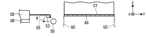
- the pulling means 52 drives the linear motor 58 to lower the pulling member 55 and pull the pulling member 55 away from the carbon nanotube CT as shown by the solid line in FIG. 2B.
- the drawing means 52 drives the linear motor 57 and the linear motor 58 to move the drawing member 55 between the adhesive sheet AS and the support member 53 and upward as indicated by the two-dot chain line in FIG. 2C.
- the pulling means 52 drives the linear motion motor 58 to lower the pulling member 55 and cut the carbon nanotube CT transferred to the adhesive sheet AS, as indicated by the two-dot chain line in the lower part of the drawing.
- a rear end portion and a new front end portion are formed in the carbon nanotube CT, and as shown in FIG. 2D, a carbon nanotube sheet CS in which the carbon nanotube CT is transferred to the adhesive sheet AS is manufactured.
- the leading end is supported by the support member 53.
- the drawing means 52 drives the linear motor 57 and the linear motor 58 to move the drawing member 55 to the initial position as shown by a two-dot chain line in FIG.
- the unnecessary tube UC protruding from the front end and the rear end of the AS is cut.
- the feeding means 20 and the collecting means 70 drive the rotation motors 21A and 71A, so that the carbon nanotube CT to be pulled out next can be transferred to a position adjacent to the right side of the transferred carbon nanotube CT.
- the rotation motors 21A and 71A are stopped.
- the release sheet RL is peeled off from the fed raw fabric RS by the release roller 30, and the peeled release sheet RL bypasses the transfer unit 50 by the bypass roller 40.
- the detoured release sheet RL is stacked on the carbon nanotube CT by the stacking unit 60 and is recovered by the recovery unit 70 as the carbon nanotube sheet CS. Thereafter, by repeating the same operation as described above, the carbon nanotube sheet CS having the carbon nanotubes CT transferred continuously in the left-right direction of the adhesive sheet AS is manufactured.
- the carbon nanotube CT is pulled out from the forest CB in the front-rear direction intersecting the feeding direction of the adhesive sheet AS, and the carbon nanotube CT having a predetermined length is transferred to the adhesive sheet AS. Even when the AS width is changed, the carbon nanotube sheet CS in which the carbon nanotube CT is transferred to the entire adhesive sheet AS can be manufactured without changing the forest CB.
- the sheet manufacturing apparatus 10 may manufacture a carbon nanotube sheet CS in which two or more layers of carbon nanotubes CT are laminated on one surface or the other surface of the sheet, or carbon nanotubes on one surface and the other surface of the sheet.
- a carbon nanotube sheet CS in which CT is a single layer or a laminate of two or more layers may be manufactured.
- the sheet may be a laminate of carbon nanotubes arranged along the feeding direction of the sheet, and the transfer means 50 may transfer the extracted carbon nanotubes CT to the sheet.
- the sheet manufacturing apparatus 10 is not limited to one that feeds the adhesive sheet AS every time the carbon nanotube CT is transferred.
- the transfer unit 50 is provided so as to be movable in the feeding direction of the adhesive sheet AS, and the carbon nanotube CT is placed on the adhesive sheet AS.
- the adhesive sheet AS may be fed out by the feeding means 20 after being transferred a predetermined number of times.
- the feeding means 20 may produce only the adhesive sheet AS or release sheet RL as a sheet to produce a carbon nanotube sheet CS consisting only of the adhesive sheet AS or release sheet RL to which the carbon nanotube CT is transferred. There may or may not be a detour means and stacking means 60.
- the feeding means 20 feeds only the adhesive sheet AS or the release sheet RL as a sheet, and also applies the release sheet RL or the adhesive sheet AS as another sheet to the adhesive sheet AS or the release sheet RL to which the carbon nanotube CT is transferred.
- the carbon nanotube sheet CS including the adhesive sheet AS, the carbon nanotube CT, and the release sheet RL may be manufactured by supplying the supply means and laminating the supplied release sheet RL or adhesive sheet AS with the lamination means 60. .
- the feeding means 20 may feed only the base material as a sheet that does not have the adhesive layer and the release layer.
- the feeding unit 20 may include a detecting unit that detects an edge of the transferred carbon nanotube CT on the support roller 21 side.
- the feed amount of the raw fabric RS may be controlled by detecting the edge.
- the stripping means may be a plate-like blade material.
- the number of bypass rollers 40 may be one, or three or more.
- the detour unit may detour the release sheet RL downward, forward, or rearward of the transfer unit 50, or may detour the adhesive sheet AS from which the release sheet RL has been separated from the original fabric RS.
- a plurality of transfer means 50 may be provided side by side in the sheet feeding direction, or may be provided in front, rear, or both of the fed sheet.
- the transfer unit 50 may employ a structure that holds or supports the integrated object WK or the carbon nanotube CT with a chuck unit such as a mechanical chuck or a chuck cylinder, a Coulomb force, an adhesive, an adhesive sheet, or a magnetic force.
- the holding means 51 may directly hold the forest CB itself with the holding surface 54A.
- the lead-out means 52 may pull out the carbon nanotubes CT diagonally right forward or rearward or diagonally left frontward or rearward as a direction intersecting the feeding direction of the adhesive sheet AS.
- the drawing means 52 does not need to use the drawing member 55 as a cutting means.
- a cutting means such as a cutter blade, a laser cutter, a heat cutter, an air cutter, or a compressed water cutter is used. It may be provided independently in a separate body, or the separate cutting means may be used as an unnecessary tube cutting means.
- the drawing means 52 may employ a support member or a drawing member made of blade material, rubber, resin, sponge, etc., and the cross-sectional shape of the adopted member may be an ellipse, a polygon such as a triangle or a rectangle, and other shapes. May be.
- the stacking unit 60 may include a pressing force adjusting unit that adjusts the pressing force of the pressing roller 61.
- the pressing force adjusting unit adjusts the positions of the pressing roller 61 and the receiving roller 62 in the thickness direction of the original fabric RS.
- You may comprise by the linear motion motor as a drive device, and pressure detection means, such as a pressure sensor and a load cell which detect pressing force.
- the pressing roller 61 and the receiving roller 62 may be driven by a rotating motor as a driving device, or an encoder may be provided to control the amount of rotation.
- the material, type, shape and the like of the adhesive sheet AS in the present invention are not particularly limited.
- the adhesive sheet AS may be a circle, an ellipse, a polygon such as a triangle or a quadrangle, or other shapes, or may be of an adhesive form such as pressure sensitive adhesive or heat sensitive adhesive,
- the heat-sensitive adhesive sheet AS When the heat-sensitive adhesive sheet AS is employed, it may be bonded by an appropriate method such as providing an appropriate coil heater for heating the adhesive sheet AS or a heating means such as a heating side of a heat pipe.
- Such an adhesive sheet AS is, for example, a single layer having only an adhesive layer, a layer having an intermediate layer between the base material and the adhesive layer, and a cover layer on the upper surface of the base material.
- a so-called double-sided adhesive sheet that can peel the substrate from the adhesive layer may be used, and the double-sided adhesive sheet has a single-layer or multi-layer intermediate layer, It may be a single layer or multiple layers without an intermediate layer.
- the means and steps in the present invention are not limited in any way as long as they can perform the operations, functions, or steps described with respect to those means and steps.
- the process is not limited at all.
- the feeding means is not limited insofar as the sheet can be fed out, in light of the common general technical knowledge at the time of filing, and within the technical scope (explanation of other means and steps). Is omitted).
- the drive device in the embodiment includes an electric device such as a rotation motor, a linear motion motor, a linear motor, a single axis robot, an articulated robot, an actuator such as an air cylinder, a hydraulic cylinder, a rodless cylinder, and a rotary cylinder. In addition to these, a combination of them directly or indirectly may be employed (some of them overlap with those exemplified in the embodiment).
Landscapes
- Chemical & Material Sciences (AREA)
- Engineering & Computer Science (AREA)
- Materials Engineering (AREA)
- Nanotechnology (AREA)
- Organic Chemistry (AREA)
- Ceramic Engineering (AREA)
- Inorganic Chemistry (AREA)
- Carbon And Carbon Compounds (AREA)
- Laminated Bodies (AREA)
Abstract
Description
また、本発明のシート製造装置では、前記シートは、当該シートの繰出方向に沿って配列されたカーボンナノチューブが積層されたものであって、前記転写手段は、引き出されたカーボンナノチューブを前記シートに転写する、ことが好ましい。
また、本発明のシート製造方法では、前記シートは、当該シートの繰出方向に沿って配列されたカーボンナノチューブが積層されたものであって、前記転写する工程は、引き出されたカーボンナノチューブを前記シートに転写する、ことが好ましい。
また、シートに他のシートが仮着された原反から他のシートを剥離し、当該他のシートを迂回させ、シートに転写されたカーボンナノチューブに迂回させた他のシートを積層すれば、原反を支持する支持手段の個数を1つに抑えることができ、シート製造装置の小型化や原反交換の作業性向上を図ることができる。
なお、本実施形態におけるX軸、Y軸、Z軸は、それぞれが直交する関係にあり、X軸およびY軸は、所定平面内の軸とし、Z軸は、前記所定平面に直交する軸とする。さらに、本実施形態では、Y軸と平行な図1中手前側から観た場合を基準とし、方向を示した場合、「上」がZ軸の矢印方向で「下」がその逆方向、「左」がX軸の矢印方向で「右」がその逆方向、「前」が図1中手前方向であるY軸の矢印方向で「後」がその逆方向とする。
切断手段は、本実施形態の場合、引出部材55の下部によって構成されている。
先ず、作業者が原反RSを図1に示すようにセットした後、作業者または多関節ロボットやベルトコンベア等の図示しない搬送手段が、一体物WKを保持面54Aの所定位置に載置する。次いで、保持手段51が図示しない減圧手段を駆動し、保持面54Aで一体物WKを吸着保持する。その後、作業者がカーボンナノチューブCTをフォレストCBから引っ張り出し、図2A中実線で示すように、当該カーボンナノチューブCTの先端部を支持部材53上にセットする。このとき、引っ張り出されたカーボンナノチューブCTは、粘性を有するためその粘性により支持部材53に支持される。また、カーボンナノチューブCT同士がファンデルワールス力で結びついているため、引っ張り出したカーボンナノチューブCTは、引き出し方向に沿って配列した帯状のカーボンナノチューブCTとなる。
シート製造装置10は、カーボンナノチューブCTを転写する毎に接着シートASを繰り出すものに限らず、例えば、転写手段50を接着シートASの繰り出し方向に移動可能に設け、接着シートASにカーボンナノチューブCTを所定回数転写した後に繰出手段20で接着シートASを繰り出すものであってもよい。
繰出手段20は、シートとしての接着シートASまたは剥離シートRLのみを繰り出すとともに、カーボンナノチューブCTが転写された接着シートASまたは剥離シートRLに対し、他のシートとしての剥離シートRLまたは接着シートASを供給手段で供給し、当該供給された剥離シートRLまたは接着シートASを積層手段60で積層することで、接着シートAS、カーボンナノチューブCTおよび剥離シートRLからなるカーボンナノチューブシートCSを製造してもよい。
繰出手段20は、接着剤層および剥離層を有さないシートとしての基材のみを繰り出してもよい。
繰出手段20は、転写したカーボンナノチューブCTの支持ローラ21側の端縁を検出する検出手段を備えてしてもよく。当該端縁を検出することで原反RSの繰り出し量を制御してもよい。
迂回手段は、剥離シートRLを転写手段50の下方、前方または後方に迂回させてもよいし、原反RSから剥離シートRLが剥離された接着シートASを迂回させてもよい。
転写手段50は、メカチャックやチャックシリンダ等のチャック手段、クーロン力、粘着剤、粘着シート、磁力等で一体物WKやカーボンナノチューブCTを保持または支持する構成を採用してもよい。
保持手段51は、保持面54AでフォレストCBそのものを直接保持してもよい。
引出手段52は、接着シートASの繰出方向に交差する方向としての右斜め前方または後方あるいは左斜め前方または後方にカーボンナノチューブCTを引き出してもよい。
引出手段52は、引出部材55を切断手段として兼用させなくてもよく、この場合、カッター刃、レーザカッター、熱カッター、エアカッター、圧縮水カッター等の切断手段を採用し、引出部材55とは別体に独立して設けてもよいし、当該別体の切断手段を不要チューブ切断手段として兼用してもよい。
引出手段52は、ブレード材、ゴム、樹脂、スポンジ等による支持部材や引出部材を採用してもよし、採用する部材の断面形状は、楕円形、三角形や四角形等の多角形その他の形状を有してもよい。
押圧ローラ61および受けローラ62は駆動機器としての回動モータで駆動するものであってもよいし、エンコーダを設け回転量を制御してもよい。
また、前記実施形態における駆動機器は、回動モータ、直動モータ、リニアモータ、単軸ロボット、多関節ロボット等の電動機器、エアシリンダ、油圧シリンダ、ロッドレスシリンダおよびロータリシリンダ等のアクチュエータ等を採用することができる上、それらを直接的又は間接的に組み合せたものを採用することもできる(実施形態で例示したものと重複するものもある)。
20…繰出手段
30…剥離ローラ(剥離手段)
40…迂回ローラ(迂回手段)
50…転写手段
52…引出手段
55…引出部材(切断手段)
60…積層手段
AS…接着シート(シート)
CB…フォレスト(成長体)
CS…カーボンナノチューブシート
CT…カーボンナノチューブ
RL…剥離シート(他のシート)
RS…原反
Claims (5)
- カーボンナノチューブがシートに転写されたカーボンナノチューブシートを製造するシート製造装置であって、
前記シートを繰り出す繰出手段と、
前記シートに所定長さのカーボンナノチューブを転写する転写手段とを備え、
前記転写手段は、カーボンナノチューブを成長させた成長体から前記シートの繰出方向に交差する方向に前記カーボンナノチューブを引き出す引出手段と、当該引き出されたカーボンナノチューブを切断する切断手段とを備えることを特徴とするシート製造装置。 - 前記シートの一方の面に他のシートが仮着された原反から前記他のシートを剥離する剥離手段と、
当該剥離された他のシートを迂回させる迂回手段と、
前記シートに転写されたカーボンナノチューブに他のシートを積層する積層手段とを備えることを特徴とする請求項1に記載のシート製造装置。 - 前記シートは、当該シートの繰出方向に沿って配列されたカーボンナノチューブが積層されたものであって、
前記転写手段は、引き出されたカーボンナノチューブを前記シートに転写することを特徴とする請求項1または請求項2に記載のシート製造装置。 - カーボンナノチューブがシートに転写されたカーボンナノチューブシートを製造するシート製造方法であって、
前記シートを繰り出す工程と、
前記カーボンナノチューブを成長させた成長体から前記シートの繰出方向に交差する方向に前記カーボンナノチューブを引き出して切断することで前記カーボンナノチューブを前記シートに転写する工程とを備えることを特徴とするシート製造方法。 - 前記シートは、当該シートの繰出方向に沿って配列されたカーボンナノチューブが積層されたものであって、
前記転写する工程は、引き出されたカーボンナノチューブを前記シートに転写することを特徴とする請求項4に記載のシート製造方法。
Priority Applications (3)
| Application Number | Priority Date | Filing Date | Title |
|---|---|---|---|
| US15/559,015 US10280087B2 (en) | 2015-03-17 | 2015-11-12 | Sheet manufacturing device and manufacturing method |
| JP2017506017A JP6554535B2 (ja) | 2015-03-17 | 2015-11-12 | シート製造装置および製造方法 |
| CN201580077815.2A CN107428538B (zh) | 2015-03-17 | 2015-11-12 | 片材制造装置及制造方法 |
Applications Claiming Priority (2)
| Application Number | Priority Date | Filing Date | Title |
|---|---|---|---|
| JP2015053370 | 2015-03-17 | ||
| JP2015-053370 | 2015-03-17 |
Publications (1)
| Publication Number | Publication Date |
|---|---|
| WO2016147475A1 true WO2016147475A1 (ja) | 2016-09-22 |
Family
ID=56918564
Family Applications (1)
| Application Number | Title | Priority Date | Filing Date |
|---|---|---|---|
| PCT/JP2015/081833 Ceased WO2016147475A1 (ja) | 2015-03-17 | 2015-11-12 | シート製造装置および製造方法 |
Country Status (5)
| Country | Link |
|---|---|
| US (1) | US10280087B2 (ja) |
| JP (1) | JP6554535B2 (ja) |
| CN (1) | CN107428538B (ja) |
| TW (1) | TWI665159B (ja) |
| WO (1) | WO2016147475A1 (ja) |
Cited By (3)
| Publication number | Priority date | Publication date | Assignee | Title |
|---|---|---|---|---|
| WO2018131386A1 (ja) * | 2017-01-16 | 2018-07-19 | 日立造船株式会社 | カーボンナノチューブウェブの引出方法 |
| JP2019039001A (ja) * | 2017-08-25 | 2019-03-14 | ザ・ボーイング・カンパニーThe Boeing Company | カーボンナノチューブ強化ポリマー及びその製造方法 |
| JP2021107296A (ja) * | 2019-12-27 | 2021-07-29 | 日立造船株式会社 | カーボンナノチューブ成形体の製造方法 |
Families Citing this family (3)
| Publication number | Priority date | Publication date | Assignee | Title |
|---|---|---|---|---|
| WO2019060099A2 (en) * | 2017-09-22 | 2019-03-28 | Lintec Of America, Inc. | SHEET WIDTH CONTROL OF NANOFIBRES |
| US11531267B2 (en) | 2020-07-02 | 2022-12-20 | Himax Technologies Limited | Imprinting apparatus |
| CN116547117A (zh) * | 2020-12-10 | 2023-08-04 | 鲍勃斯脱梅克斯股份有限公司 | 用于保持平坦的柔性部件的定位装置和定位组件以及片材材料加工机 |
Citations (4)
| Publication number | Priority date | Publication date | Assignee | Title |
|---|---|---|---|---|
| JP2008542953A (ja) * | 2005-06-02 | 2008-11-27 | イーストマン コダック カンパニー | カーボンナノチューブを含む導電性層を有するタッチスクリーン |
| JP2012183583A (ja) * | 2011-02-18 | 2012-09-27 | Jx Nippon Mining & Metals Corp | グラフェン製造用銅箔及びそれを用いたグラフェンの製造方法 |
| JP2014152049A (ja) * | 2013-02-06 | 2014-08-25 | Hitachi Zosen Corp | カーボンナノチューブの剥離装置 |
| JP2015040134A (ja) * | 2013-08-20 | 2015-03-02 | 日立造船株式会社 | カーボンナノチューブの製造装置 |
Family Cites Families (9)
| Publication number | Priority date | Publication date | Assignee | Title |
|---|---|---|---|---|
| US6946205B2 (en) * | 2002-04-25 | 2005-09-20 | Matsushita Electric Industrial Co., Ltd. | Wiring transfer sheet and method for producing the same, and wiring board and method for producing the same |
| US7744793B2 (en) * | 2005-09-06 | 2010-06-29 | Lemaire Alexander B | Apparatus and method for growing fullerene nanotube forests, and forming nanotube films, threads and composite structures therefrom |
| CN101920955B (zh) | 2009-06-09 | 2012-09-19 | 清华大学 | 碳纳米管膜保护结构及其制备方法 |
| CN103159204B (zh) | 2011-12-09 | 2015-03-25 | 北京富纳特创新科技有限公司 | 碳纳米管膜的制备方法 |
| CN102602118B (zh) * | 2012-02-23 | 2015-03-25 | 苏州汉纳材料科技有限公司 | 一种碳纳米管薄膜的转印方法 |
| JP2014027171A (ja) * | 2012-07-27 | 2014-02-06 | Lintec Corp | シート貼付装置およびシート貼付方法 |
| JP5896038B2 (ja) | 2012-10-15 | 2016-03-30 | 信越化学工業株式会社 | ナノカーボン膜の作製方法 |
| JP6071763B2 (ja) * | 2013-06-05 | 2017-02-01 | 日立造船株式会社 | カーボンナノチューブシートの製造方法及びカーボンナノチューブシート |
| BR102014027603B1 (pt) * | 2014-11-05 | 2017-03-07 | Jeffrey Arippol Giuseppe | processo de obtenção de fita de rótulos-bula autoadesivos, sem fita de suporte e proteção |
-
2015
- 2015-11-12 WO PCT/JP2015/081833 patent/WO2016147475A1/ja not_active Ceased
- 2015-11-12 JP JP2017506017A patent/JP6554535B2/ja not_active Expired - Fee Related
- 2015-11-12 CN CN201580077815.2A patent/CN107428538B/zh active Active
- 2015-11-12 US US15/559,015 patent/US10280087B2/en active Active
- 2015-11-26 TW TW104139433A patent/TWI665159B/zh active
Patent Citations (4)
| Publication number | Priority date | Publication date | Assignee | Title |
|---|---|---|---|---|
| JP2008542953A (ja) * | 2005-06-02 | 2008-11-27 | イーストマン コダック カンパニー | カーボンナノチューブを含む導電性層を有するタッチスクリーン |
| JP2012183583A (ja) * | 2011-02-18 | 2012-09-27 | Jx Nippon Mining & Metals Corp | グラフェン製造用銅箔及びそれを用いたグラフェンの製造方法 |
| JP2014152049A (ja) * | 2013-02-06 | 2014-08-25 | Hitachi Zosen Corp | カーボンナノチューブの剥離装置 |
| JP2015040134A (ja) * | 2013-08-20 | 2015-03-02 | 日立造船株式会社 | カーボンナノチューブの製造装置 |
Cited By (6)
| Publication number | Priority date | Publication date | Assignee | Title |
|---|---|---|---|---|
| WO2018131386A1 (ja) * | 2017-01-16 | 2018-07-19 | 日立造船株式会社 | カーボンナノチューブウェブの引出方法 |
| JP2018115083A (ja) * | 2017-01-16 | 2018-07-26 | 日立造船株式会社 | カーボンナノチューブウェブの引出方法 |
| JP2019039001A (ja) * | 2017-08-25 | 2019-03-14 | ザ・ボーイング・カンパニーThe Boeing Company | カーボンナノチューブ強化ポリマー及びその製造方法 |
| JP7268975B2 (ja) | 2017-08-25 | 2023-05-08 | ザ・ボーイング・カンパニー | カーボンナノチューブ強化ポリマー及びその製造方法 |
| JP2021107296A (ja) * | 2019-12-27 | 2021-07-29 | 日立造船株式会社 | カーボンナノチューブ成形体の製造方法 |
| JP7285212B2 (ja) | 2019-12-27 | 2023-06-01 | 日立造船株式会社 | カーボンナノチューブ成形体の製造方法 |
Also Published As
| Publication number | Publication date |
|---|---|
| TW201706208A (zh) | 2017-02-16 |
| CN107428538A (zh) | 2017-12-01 |
| US10280087B2 (en) | 2019-05-07 |
| US20180079646A1 (en) | 2018-03-22 |
| JPWO2016147475A1 (ja) | 2017-12-28 |
| JP6554535B2 (ja) | 2019-07-31 |
| TWI665159B (zh) | 2019-07-11 |
| CN107428538B (zh) | 2021-02-09 |
Similar Documents
| Publication | Publication Date | Title |
|---|---|---|
| JP6554535B2 (ja) | シート製造装置および製造方法 | |
| JP5439225B2 (ja) | プリプレグ積層ヘッド及びこれを備えたプリプレグ自動積層装置 | |
| KR101459065B1 (ko) | 터치 스크린 패널 제작용 라미네이션 장치 | |
| JP6575356B2 (ja) | 強化繊維シート製造装置 | |
| JP2013074102A (ja) | シート貼付装置及び貼付方法、並びに、シート製造装置及び製造方法 | |
| CN108705585A (zh) | 粘合带切割装置 | |
| JP6106529B2 (ja) | 切断補助具、長尺体繋ぎ装置及び方法 | |
| TWI733843B (zh) | 長條體連接裝置及連接方法 | |
| JP6069020B2 (ja) | シート貼付装置および貼付方法 | |
| JP5947171B2 (ja) | 長尺体接続装置 | |
| CN119560606A (zh) | 二次电池电极制备工序用卷绕装置 | |
| JP4776701B2 (ja) | フィルム貼り合わせ装置 | |
| US10315923B2 (en) | Sheet manufacturing device and sheet manufacturing method | |
| JP5539831B2 (ja) | シート製造装置および製造方法 | |
| JP5881533B2 (ja) | シート貼付装置 | |
| JP6668052B2 (ja) | 巻回装置 | |
| JP2020120026A (ja) | シート製造装置およびシート製造方法 | |
| JP3225039U (ja) | 巻取装置 | |
| JP7346092B2 (ja) | シート回収装置およびシート回収方法 | |
| JP2023039258A (ja) | シート貼付装置およびシート貼付方法 | |
| JP2013244987A (ja) | シート貼付装置及び貼付方法 | |
| JP5572254B2 (ja) | シート剥離装置及び剥離方法 | |
| JP5906160B2 (ja) | 長尺体位置決め装置及び位置決め方法 | |
| WO2023085074A1 (ja) | シート貼付装置およびシート貼付方法 | |
| JP2020057745A (ja) | 不要シート除去装置および不要シート除去方法 |
Legal Events
| Date | Code | Title | Description |
|---|---|---|---|
| 121 | Ep: the epo has been informed by wipo that ep was designated in this application |
Ref document number: 15885567 Country of ref document: EP Kind code of ref document: A1 |
|
| ENP | Entry into the national phase |
Ref document number: 2017506017 Country of ref document: JP Kind code of ref document: A |
|
| WWE | Wipo information: entry into national phase |
Ref document number: 15559015 Country of ref document: US |
|
| NENP | Non-entry into the national phase |
Ref country code: DE |
|
| 122 | Ep: pct application non-entry in european phase |
Ref document number: 15885567 Country of ref document: EP Kind code of ref document: A1 |