WO2016147229A1 - Cuve de décantation - Google Patents
Cuve de décantation Download PDFInfo
- Publication number
- WO2016147229A1 WO2016147229A1 PCT/JP2015/005288 JP2015005288W WO2016147229A1 WO 2016147229 A1 WO2016147229 A1 WO 2016147229A1 JP 2015005288 W JP2015005288 W JP 2015005288W WO 2016147229 A1 WO2016147229 A1 WO 2016147229A1
- Authority
- WO
- WIPO (PCT)
- Prior art keywords
- filter medium
- water
- sedimentation basin
- treated
- medium layer
- Prior art date
Links
- XLYOFNOQVPJJNP-UHFFFAOYSA-N water Substances O XLYOFNOQVPJJNP-UHFFFAOYSA-N 0.000 claims abstract description 184
- 238000001914 filtration Methods 0.000 claims abstract description 77
- 238000005192 partition Methods 0.000 claims abstract description 45
- 239000007787 solid Substances 0.000 claims abstract description 29
- 238000005273 aeration Methods 0.000 claims abstract description 25
- 230000001376 precipitating effect Effects 0.000 claims abstract description 8
- 238000003756 stirring Methods 0.000 claims abstract description 5
- 238000004062 sedimentation Methods 0.000 claims description 134
- 238000001556 precipitation Methods 0.000 claims description 31
- 238000005406 washing Methods 0.000 claims description 18
- 238000004140 cleaning Methods 0.000 abstract description 17
- 239000000463 material Substances 0.000 abstract description 5
- 239000013049 sediment Substances 0.000 description 6
- 230000007423 decrease Effects 0.000 description 5
- 239000002244 precipitate Substances 0.000 description 5
- 230000006866 deterioration Effects 0.000 description 4
- 238000009434 installation Methods 0.000 description 4
- 238000000034 method Methods 0.000 description 4
- 230000000052 comparative effect Effects 0.000 description 3
- 230000005484 gravity Effects 0.000 description 3
- 239000010865 sewage Substances 0.000 description 3
- 238000006243 chemical reaction Methods 0.000 description 2
- 230000008569 process Effects 0.000 description 2
- 239000002351 wastewater Substances 0.000 description 2
- 230000000903 blocking effect Effects 0.000 description 1
- 230000008859 change Effects 0.000 description 1
- 238000011049 filling Methods 0.000 description 1
- 230000001771 impaired effect Effects 0.000 description 1
- 230000006872 improvement Effects 0.000 description 1
- 238000002347 injection Methods 0.000 description 1
- 239000007924 injection Substances 0.000 description 1
- 239000007788 liquid Substances 0.000 description 1
- 239000002184 metal Substances 0.000 description 1
- 230000004048 modification Effects 0.000 description 1
- 238000012986 modification Methods 0.000 description 1
- 239000011148 porous material Substances 0.000 description 1
- 238000004080 punching Methods 0.000 description 1
- 238000011084 recovery Methods 0.000 description 1
- 239000011347 resin Substances 0.000 description 1
- 229920005989 resin Polymers 0.000 description 1
- 230000000630 rising effect Effects 0.000 description 1
- 238000000926 separation method Methods 0.000 description 1
- 238000002791 soaking Methods 0.000 description 1
- 238000000638 solvent extraction Methods 0.000 description 1
- 238000004065 wastewater treatment Methods 0.000 description 1
Images

Classifications
-
- B—PERFORMING OPERATIONS; TRANSPORTING
- B01—PHYSICAL OR CHEMICAL PROCESSES OR APPARATUS IN GENERAL
- B01D—SEPARATION
- B01D21/00—Separation of suspended solid particles from liquids by sedimentation
-
- B—PERFORMING OPERATIONS; TRANSPORTING
- B01—PHYSICAL OR CHEMICAL PROCESSES OR APPARATUS IN GENERAL
- B01D—SEPARATION
- B01D21/00—Separation of suspended solid particles from liquids by sedimentation
- B01D21/02—Settling tanks with single outlets for the separated liquid
-
- B—PERFORMING OPERATIONS; TRANSPORTING
- B01—PHYSICAL OR CHEMICAL PROCESSES OR APPARATUS IN GENERAL
- B01D—SEPARATION
- B01D21/00—Separation of suspended solid particles from liquids by sedimentation
- B01D21/18—Construction of the scrapers or the driving mechanisms for settling tanks
-
- B—PERFORMING OPERATIONS; TRANSPORTING
- B01—PHYSICAL OR CHEMICAL PROCESSES OR APPARATUS IN GENERAL
- B01D—SEPARATION
- B01D21/00—Separation of suspended solid particles from liquids by sedimentation
- B01D21/24—Feed or discharge mechanisms for settling tanks
-
- B—PERFORMING OPERATIONS; TRANSPORTING
- B01—PHYSICAL OR CHEMICAL PROCESSES OR APPARATUS IN GENERAL
- B01D—SEPARATION
- B01D24/00—Filters comprising loose filtering material, i.e. filtering material without any binder between the individual particles or fibres thereof
- B01D24/02—Filters comprising loose filtering material, i.e. filtering material without any binder between the individual particles or fibres thereof with the filter bed stationary during the filtration
- B01D24/10—Filters comprising loose filtering material, i.e. filtering material without any binder between the individual particles or fibres thereof with the filter bed stationary during the filtration the filtering material being held in a closed container
- B01D24/16—Upward filtration
-
- B—PERFORMING OPERATIONS; TRANSPORTING
- B01—PHYSICAL OR CHEMICAL PROCESSES OR APPARATUS IN GENERAL
- B01D—SEPARATION
- B01D24/00—Filters comprising loose filtering material, i.e. filtering material without any binder between the individual particles or fibres thereof
- B01D24/02—Filters comprising loose filtering material, i.e. filtering material without any binder between the individual particles or fibres thereof with the filter bed stationary during the filtration
- B01D24/20—Filters comprising loose filtering material, i.e. filtering material without any binder between the individual particles or fibres thereof with the filter bed stationary during the filtration the filtering material being provided in an open container
- B01D24/26—Upward filtration
-
- B—PERFORMING OPERATIONS; TRANSPORTING
- B01—PHYSICAL OR CHEMICAL PROCESSES OR APPARATUS IN GENERAL
- B01D—SEPARATION
- B01D24/00—Filters comprising loose filtering material, i.e. filtering material without any binder between the individual particles or fibres thereof
- B01D24/46—Regenerating the filtering material in the filter
-
- B—PERFORMING OPERATIONS; TRANSPORTING
- B01—PHYSICAL OR CHEMICAL PROCESSES OR APPARATUS IN GENERAL
- B01D—SEPARATION
- B01D29/00—Filters with filtering elements stationary during filtration, e.g. pressure or suction filters, not covered by groups B01D24/00 - B01D27/00; Filtering elements therefor
- B01D29/62—Regenerating the filter material in the filter
- B01D29/66—Regenerating the filter material in the filter by flushing, e.g. counter-current air-bumps
Definitions
- the present invention relates to a sedimentation basin, and more particularly to a sedimentation basin that can be suitably used as a final sedimentation basin for a sewage treatment plant.
- a water treatment system including a first sedimentation basin, a biological reaction tank, and a final sedimentation basin is used.
- a sedimentation basin such as a first sedimentation basin or a final sedimentation basin
- a sedimentation basin with a part.
- the sedimentation basin provided with this precipitation part and the filtration part, since the to-be-processed water which precipitated some solid content in the precipitation part can be further filtered in a filtration part, the process from which solid content was fully removed You can get water.
- the filtration section of the sedimentation basin includes a filter medium layer composed of a plurality of filter media, an upper screen disposed above the filter media layer to prevent the filter media from flowing out, and disposed below the filter media layer. And a lower screen that supports the filter medium that constitutes the filter medium layer, and uses a filtration unit that performs filtration by allowing the water to be treated to flow through the filter medium layer in an upward flow (Japanese Patent Laid-Open No. Hei 8- 257585, International Publication No. 2012/161339).
- the filter medium layer of the filtration unit is usually washed every predetermined time or when the solid-liquid separation performance of the filtration unit is deteriorated.
- the filter medium layer is usually washed by injecting a gas such as air into the filtration unit and causing the filter medium constituting the filter medium layer to flow by the water flow generated by the gas injection.
- the conventional sedimentation basin described above has room for improvement in that a sufficiently high speed water flow cannot be generated when gas is ejected into the filtration section, and the filter medium cannot be sufficiently flowed. It was. Therefore, the conventional sedimentation basin has been required to increase the washing efficiency by generating a high-speed water flow when washing the filter medium layer.
- the conventional sedimentation basin includes not only a filtration part but also a precipitation part.
- a high-speed water flow is generated in the filtration part during the cleaning of the filter medium layer to increase the cleaning efficiency, while the function of the precipitation part is not impaired by the water flow generated during the cleaning of the filter medium layer.
- the sedimentation basin is also required to suppress the occurrence of a short circuit flow or the like on the sedimentation portion side due to the water flow generated when the filter medium layer is washed, and the sediment soaring.
- this invention aims at providing a sedimentation basin provided with a sedimentation part and a filtration part, Comprising: The sedimentation basin which can wash
- the sedimentation basin of the present invention comprises a precipitation part for precipitating solids in the water to be treated, and water to be treated that has passed through the precipitation part.
- a sedimentation basin comprising a filtration part for filtering in an upward flow, wherein the filtration part comprises a plurality of treated water flow paths formed by partition walls extending in the depth direction of the sedimentation basin,
- the water flow path includes a filter medium layer composed of a plurality of filter media, an upper screen provided above the filter media layer to prevent the filter media from flowing out, and treated water obtained by filtering the water to be treated through the filter media layer.
- a gas jet for stirring the filter medium layer by aeration when washing the filter medium layer, and in the depth direction of the settling basin the gas jet is the water flow to be treated. It is located above the lower end of the partition that defines the path.
- “extends in the depth direction of the sedimentation basin” means extending in the depth direction of the sedimentation basin, and “extends in the depth direction of the sedimentation basin”. In addition to the case of extending in the direction along the depth direction of the sedimentation basin (usually the vertical direction), the case of extending in the direction along the depth direction of the sedimentation basin included.
- the gas outlet in the depth direction of the sedimentation basin, it is preferable that the gas outlet is located 70 mm or more above the lower end of the partition wall that defines the treated water flow path. If the distance along the depth direction of the sedimentation basin between the gas outlet and the lower end of the partition wall is 70 mm or more, it further suppresses the rise of sediment in the sedimentation part, and sufficiently suppresses the deterioration of the function of the sedimentation part. Because it can be done.
- the gas outlet is located below the lower end of the filter medium layer in the depth direction of the sedimentation basin. If the gas outlet is located below the lower end of the filter medium layer, the filter medium constituting the filter medium layer can be flowed more satisfactorily by aeration from the gas outlet, and the filter medium layer can be washed more efficiently. Because it can.
- the “lower end of the filter medium layer” refers to the lower end of the filter medium layer in a state where the water to be treated is not filtered.
- the said to-be-processed water flow path is further equipped with the horizontal plate extended in the horizontal direction under the said gas jet nozzle.
- a horizontal plate is provided on the lower side of the gas ejection port, it is possible to further suppress the rise of the precipitate in the precipitation portion during the cleaning of the filter medium layer, and to sufficiently suppress the deterioration of the function of the precipitation portion.
- “extending in the horizontal direction” means extending in the horizontal direction, and “extending in the horizontal direction” extends in a direction along the horizontal direction. In addition to the case where it extends, the case where it inclines with respect to the direction along a horizontal direction is included.
- the filtration part can be efficiently washed while suppressing the deterioration of the function of the precipitation part.
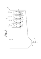
- FIG. 2 is an explanatory view showing a state of a water flow in the sedimentation basin shown in FIG. 1 when the filter medium layer of the filtration unit is washed, in a cross section taken along line AA in FIG.
- FIG. 2 shows the mode of the water flow at the time of wash
- FIG. 2 shows the mode of the water flow at the time of wash
- the sedimentation basin of this invention is not specifically limited, For example, it can be used as a final sedimentation basin provided in the back
- the treated water flow path 4 through which the treated water obtained by filtering the treated water in the filtering unit 3 and the filter medium layer 35 provided in the filtering unit 3 are washed in the filtering unit 3 of the sedimentation tank 1.
- a cleaning drainage channel (not shown) through which the discharged cleaning drainage flows is provided.
- the to-be-processed water which precipitated some solid content in the sedimentation part 2 is further filtered in the filtration part 3, and the treated water from which solid content was fully removed can be obtained.
- the part located under the filtration part 3 also functions as the precipitation part 2 which precipitates the solid content in to-be-processed water.
- the sedimentation unit 2 is not particularly limited, and includes a cross-flow type precipitation tank that separates the solid content from the water to be treated by sedimenting the solid content in the water to be treated by gravity sedimentation.
- a solid content discharge pipe 21 having a solid content discharge valve 22 is provided at the bottom of the sedimentation unit 2.
- the solid content precipitated in the sedimentation section 2 is obtained by always opening a solid content discharge valve 22 provided in the solid content discharge pipe 21 at a predetermined opening, for example, or by opening it every predetermined time. It is discharged from and processed.
- the sedimentation part 2 may be equipped with the inclination board which accelerates
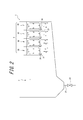
- the filtration part 3 consists of a filtration tank which filters the to-be-processed water which settled a part of solid content in the precipitation part 2 by an upward flow. And as shown to Fig.1 (a) and (b), the filtration part 3 is provided over the side wall located up and down in Fig.1 (a) of the sedimentation basin 1, and the depth of the sedimentation basin 1 is shown. A plurality of (four in the illustrated example) to-be-treated water flow paths 30 are provided that are partitioned by a plurality of (four in the illustrated example) partition walls 31 extending in the vertical direction (the vertical direction in FIG. 1B). . In the sedimentation basin 1, the upper side of the lower end of the partition wall 31 is the filtration unit 3. In addition, the length (the length of the left-right direction in FIG. 1 (a) and (b)) of the filtration part 3 is not specifically limited, It is 1/4 or more and 3/4 or less of the full length of the sedimentation tank 1. be able to.
- each water channel 30 to be treated is a region surrounded by the partition wall 31 and the wall surface of the sedimentation basin 1, and the water to be treated is passed through each water channel 30 to be treated in an upward direction.
- each to-be-processed water flow path 30 is below the filter medium layer 35, the filter medium layer 35 which consists of several filter media with which the process water flow path 30 was filled, the upper screen 33 provided above the filter medium layer 35, and the filter medium layer 35.
- the lower screen 34 provided, and the treated water outflow part 32 from which the treated water obtained by filtering to-be-treated water with the filter material layer 35 flow out to the treated water flow path 4 are provided.
- each of the water channels 30 to be treated includes a gas outlet 36 of an aeration pipe (not shown) used when stirring and washing the filter medium layer 35 using a swirling flow generated by aeration, and a lower side of the gas outlet 36. And a horizontal plate 37 provided on the side.
- Each partition wall 31 extends in a direction along the depth direction (vertical direction) of the sedimentation tank 1.
- Each partition wall 31 is provided so as to be separated from the bottom surface of the sedimentation basin 1, and the treated water flow path 30 and the sedimentation part 2 communicate with each other at the lower part of the sedimentation basin 1. Further, in the depth direction of the sedimentation basin 1, the upper end of each partition wall 31 is positioned above the water surface, and the lower end of each partition wall 31 is positioned below the gas outlet 36.
- the partition 31 is not specifically limited, It can form using a partition plate or a concrete wall.
- the treated water outflow part 32 is a part where treated water overflows from the treated water flow path 30 to the treated water flow path 4, and is located above the upper screen 33 in the example shown in FIG. 1.
- the upper screen 33 prevents the filter medium constituting the filter medium layer 35 from flowing out of the treated water channel 30.
- the lower screen 34 prevents the filter medium constituting the filter medium layer 35 from dropping or flowing out from the treated water flow path 30 downward. Specifically, the lower screen 34 prevents the filter medium from falling downward when the filter medium constituting the filter medium layer is filled in the water channel 30 to be treated, or the solid content precipitated in the precipitation unit 2 is solidified. The filter medium is prevented from flowing out of the water channel 30 to be treated due to the downward flow generated when discharged through the distribution pipe 21.
- the upper screen 33 and the lower screen 34 are not particularly limited as long as the screen has a pore diameter smaller than that of the filter medium constituting the filter medium layer 35, and known screens such as punching metal and wire mesh can be used. .
- the filter medium layer 35 provided between the upper screen 33 and the lower screen 34 is formed by, for example, filling a plurality of filter media constituting the filter medium layer 35 on the lower screen 34 in the water channel 30 to be treated.
- the filter medium constituting the filter medium layer 35 is not particularly limited, and for example, a resin filter medium can be used.
- a filter medium although the filter medium of arbitrary shapes can be used, it is preferable to use a cylindrical filter medium.
- the filter medium layer 35 is configured using a cylindrical filter medium, when the water to be treated passes through the hollow portions of the cylindrical filter medium filled randomly and the gaps between the filter media, each cylindrical filter medium or between the filter mediums This is because the solids in the water to be treated are separated better by the filter medium layer 35 by functioning as a slanted plate settling device with a small gap.
- any of a settling filter medium that is, a filter medium that settles in stationary water to be treated
- a floating filter medium that is, a filter medium that floats in stationary water to be treated
- the filter medium which has the specific gravity of the grade which floats in the water flow of to-be-processed water, and it is more preferable to use the floating filter medium whose specific gravity is less than 1.0.
- the filter medium can be filled into the treated water flow path 30 by putting the filter medium in a state where water is stored in the treated water flow path 30, so that the lower screen 34 may not be provided.
- the aeration pipe having the gas ejection port 36 is connected to an air supply source such as a blower (not shown) provided outside the treated water flow path 30.
- the aeration pipe and the blower having the gas ejection port 36 function as an aeration apparatus that stirs and cleans the filter medium layer 35 using a swirling flow generated by aeration of air as a gas.
- an air pipe valve (not shown) is provided at a connection portion between the aeration pipe and the blower to prevent the water to be treated from flowing backward during filtration.
- the gas jet nozzle 36 is located above the lower end of the partition 31 which divides the filtration part 3 and forms the said to-be-processed water flow path 30. ing. Further, the gas ejection port 36 is treated in the sedimentation basin 1 rather than in the center of each treated water channel 30 when viewed in the length direction of the sedimentation basin 1 (left and right directions in FIGS. 1A and 1B). It is provided on the water inlet side (left side in FIG. 1B).
- the horizontal plate 37 provided in the lower side of the gas jet nozzle 36 is extended in the direction along a horizontal direction, The lower side of the gas ejection port 36 is covered without blocking the entire surface.
- the horizontal plate 37 covers the lower side of the gas outlet 36 provided on the inflow side of the water to be treated to the sedimentation basin 1 from the center of the water channel 30 to be treated.
- one end is connected to the lower end of the partition wall 31 on the inlet side of the water to be treated into the sedimentation basin 1.
- cleaning of the filter medium layer 35 are implemented as follows.
- the cleaning of the filter medium layer 35 is not particularly limited and can be performed, for example, when a predetermined time has elapsed.
- the water pipe valve provided at the connection portion between the aeration pipe and the blower is closed, and the water to be treated is passed through the water flow path 30 in the upward direction while the blower is stopped.
- the clean treated water obtained by filtering the treated water with the filter medium layer 35 provided in the treated water flow path 30 passes through the treated water outflow part 32 and the treated water flow path 4 (for example, treated water tank). Etc.).
- the sedimentation basin 1 provided with the precipitation part 2 and the filtration part 3 mentioned above, since the to-be-processed water which settled a part of solid content in the precipitation part 2 can be further filtered in the filtration part 3, it is solid.
- the treated water from which the minutes have been sufficiently removed can be obtained.
- the air piping valve provided in the connection part of an aeration pipe and a blower is opened, and the to-be-treated water as a wash water flows upward into each to-be-treated water flow path 30 in the state which operated the blower. Then, the filter medium layer 35 is stirred and washed. Then, in the filtration unit 3 that is cleaning the filter medium layer 35, a swirl flow is generated by the air supplied from the gas outlet 36 into each treated water flow path 30 via the blower and the aeration pipe, thereby forming the filter medium layer 35. The filter medium that flows is dispersed.
- the blower and the aeration pipe having the gas ejection port 36 function as an aeration device that agitates the filter medium layer 35 by aeration.
- the solid content captured by the filter medium layer 35 is removed from the filter medium layer 35.
- the washing waste water containing the solid content removed from the filter medium layer 35 is sent to the outside (for example, a washing waste water treatment apparatus or the like) through a washing drain passage (not shown).
- the partition wall 31 is provided to partition the filtration unit 3 into a plurality of water channels 30 to be treated, and aeration is performed from the gas jets 36 provided in each water channel 30 to be treated.
- a high-speed and powerful swirl flow can be easily generated in each treated water channel 30. Therefore, in the sedimentation basin 1, the filter medium constituting the filter medium layer 35 can be sufficiently flowed by the high-speed and powerful swirl flow, and the filter medium layer 35 can be efficiently washed.
- the position of the gas jet port 36 is set at the lower end of the partition wall 31. If the position is lower than that, the sediment rises in the sedimentation part 2 due to the occurrence of a short circuit current or the like, and the sedimentation function itself of the sedimentation part 2 may be lost.
- the state of the water flow when the filter medium layer is washed in the sedimentation basin 1 ⁇ / b> B in which the gas ejection port 36 is disposed below the lower end of the partition wall 31 is indicated by an arrow.
- the gas outlet 36 When the gas outlet 36 is disposed below the lower end, when a swirling flow indicated by arrows b, c, d, e is generated in the treated water flow path 30B by aeration, a part of the water flow b is The resulting water stream a acquires water from a direction of 180 degrees.
- the flow rate of the treated water flowing into the settling basin and the flow rate of the treated water flowing out of the settling basin are equal to each other, which is the difference between the water flow a and the water flow f.
- the size of the water stream b is also constant.
- the size of the water stream b is the sum of the water stream a and the water stream e
- the water stream e that is turned from the water stream d when the water stream a becomes large.
- the size is negligibly small compared to the size of the water stream b. Therefore, the swirl flow indicated by arrows b, c, d, and e cannot be formed.
- the difference between the water flow a and the water flow f is constant under the condition that the amount of water to be treated is constant, the water flow f increases when the water flow a is large.
- the water exchange between the precipitation part 2 and the filtration part 3 becomes intense, thereby causing the already precipitated solid content to rise so that the precipitation function itself of the precipitation part 2 is lost.
- the gas ejection port 36 is provided above the lower end of the partition wall 31, as shown by arrows in FIG. 2, the water flow a Does not acquire water from the direction of 180 degrees, and the size of the water flow a is small (approximately equal to the inflow amount of the water to be treated into the settling basin 1).
- the size of the water flow e turned from the water flow d increases, and the swirl flow indicated by the arrows b, c, d, and e is well formed.
- the difference between the water flow a and the water flow f is constant under the condition that the amount of water to be treated is constant, the water flow f becomes small when the water flow a is small.
- water exchange between the precipitation part 2 and the filtration part 3 is greatly suppressed, so that the precipitation in the precipitation part 2 can be prevented from rising, while suppressing a decrease in the precipitation function of the precipitation part 2, Efficient cleaning of the filtration unit 3 by the swirling flow can be realized.
- the gas jet nozzle 36 is provided in the inflow side of the to-be-treated water to the sedimentation basin 1 rather than the center of the to-be-treated water flow path 30, Then, even if the gas jet port is provided on the side opposite to the inlet side of the water to be treated into the settling basin 1 from the center of the water channel to be treated, it is powerful at high speed while suppressing the deterioration of the function of the precipitation part 2.
- the filtering unit 3 can be efficiently cleaned by a simple swirling flow.
- the gas outlet when the gas outlet is provided on the side opposite to the inlet side of the water to be treated to the settling basin 1 from the center of the water channel to be treated, the downward water flow f flows to the settling basin 1. Since the position of the gas jet 36 and the upward water flow a is away from the inlet of the water to be treated into the settling basin 1, It is possible to prevent the sediment from flying up at the portion located on the inlet side of the water to be treated. Further, from the viewpoint of causing a swirling flow in the filtration unit, the gas outlet 36 is located on the inlet side of the water to be treated to the settling basin 1 or on the side opposite to the inlet side rather than the center of the water passage 30 to be treated.
- the horizontal distance from the partition wall 31 on the inlet side of the water to be treated to the sedimentation basin 1 or the side opposite to the inlet side is within 1 ⁇ 4 or less of the interval between the adjacent partition walls 31. More preferably, it is provided along the partition wall 31.
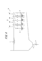
- the sedimentation basin of the present invention it is not necessary to provide the horizontal plate 37 below each gas outlet 36 as in the sedimentation basin 1A shown in FIG. 3, but in the sedimentation basin 1 shown in FIG. 1 and FIG. Since the horizontal plate 37 is provided below each gas jet 36, the state of the water flow when the filter medium layer is washed is compared with the sedimentation basin 1A indicated by the arrow in FIG. In addition, the filtration unit 3 can be efficiently washed by a stronger and faster swirling flow. Specifically, in the sedimentation basin 1A not provided with the horizontal plate 37 as shown in FIG. 3, the water flow a that is a part of the water flow b acquires water from a direction of 90 degrees.
- the size of the water flow a is larger than that of the settling basin 1 shown in FIGS. 1 and 2, and as a result, the size of the water flow e turned from the water flow d is smaller than that of the settling basin 1 shown in FIGS. Become. Further, since the difference between the water flow a and the water flow f is constant under the condition that the amount of water to be treated is constant, the water flow f increases when the water flow a is large. As a result, in the sedimentation basin 1A not provided with the horizontal plate 37 as shown in FIG. 3, the water exchange between the sedimentation unit 2 and the filtration unit 3 is larger than that in the sedimentation basin 1 shown in FIG. 1 and FIG. There is a risk that the already precipitated solid content will rise.
- the sedimentation basin 1 provided with the horizontal plate 37 since the horizontal plate 37 functions like a baffle plate as shown in FIG. 2 in the state of the water flow when the filter medium layer is washed, the sedimentation basin shown in FIG. Compared with 1A, the magnitude of the water stream e turned from the water stream d increases, and the flow velocity of the swirling flow indicated by the arrows b, c, d, e increases, while the water stream a decreases.
- the sedimentation basin 1 provided with the horizontal plate 37 the water exchange between the sedimentation part 2 and the filtration part 3 can be greatly suppressed, and the precipitation of the sediment in the sedimentation part 2 can be prevented. Efficient cleaning of the filtration unit 3 by the swirl flow can be realized while suppressing a decrease in the precipitation function of the unit 2.
- the sedimentation basin of this invention was demonstrated using an example, the sedimentation basin of this invention is not limited to the said example, A change can be suitably added to the sedimentation basin of this invention.
- the position of the gas ejection port 36 is set to one place in each treated water flow path 30.
- you may provide an exit in several positions.
- the horizontal plate 37 is provided integrally with the partition wall 31 at the lower end of the partition wall 31.
- the installation position and installation method of the horizontal plate 37 are As long as the lower side can be covered, any installation position and installation method can be adopted.
- the thickness of the filter medium layer 35 in a state where the water to be treated is not filtered is preferably, for example, 500 mm or more, and 900 mm or less. It is preferable that the thickness is 700 mm or less.
- the depth of the sedimentation basin 1 between the upper screen 33 and the lower screen 34 is preferably 200 mm or more larger than the thickness of the filter medium layer 35.
- the arrangement interval of the partition walls 31 is preferably 2000 mm or less, more preferably 1000 mm or less, and 500 mm or less. More preferably.
- the gas outlet 36 is preferably positioned 70 mm or more above the lower end of the partition wall 31. That is, the distance in the depth direction of the sedimentation basin 1 between the gas jet 36 and the lower end of the partition wall 31 is preferably 70 mm or more. Furthermore, the distance is more preferably 100 mm or more. Furthermore, from the viewpoint of forming a swirling flow over a wide range when the filter medium layer 35 is washed and causing the filter medium to flow well, the gas ejection port 36 is positioned below the lower end of the filter medium layer 35. It is more preferable that the distance from the lower end of the filter medium layer 35 is in the range of 170 mm or more and 300 mm or less when viewed in the depth direction of the sedimentation tank 1.
- the amount of aeration from the gas outlet 36 in each treated water flow path 30 is 10 Nm 3 / hour / m 2 or more. It is preferable to set it to 12 Nm 3 / hour / m 2 or more, and it is preferable to set it to 14 Nm 3 / hour / m 2 or less.
- Example 1 Using the sedimentation basin 1A shown in FIG. 3 (a sedimentation basin having the same configuration as the sedimentation basin 1 shown in FIG. 1 except that the horizontal plate 37 is not provided), the filter medium layer was washed under the following conditions. The presence / absence of roll-up of the precipitate from the precipitation portion and the difference in the size of the head loss in the filtration portion before and after washing (before washing and after washing) were evaluated and measured. The results are shown in Table 1. In addition, the detailed specification of the used sedimentation basin 1A is as follows. Moreover, the presence or absence of winding-up of a precipitate was evaluated visually.
- a sedimentation basin including a sedimentation part and a filtration part, and capable of efficiently washing the filtration part while suppressing a decrease in the function of the sedimentation part.
Landscapes
- Chemical & Material Sciences (AREA)
- Chemical Kinetics & Catalysis (AREA)
- Filtration Of Liquid (AREA)
- Biological Treatment Of Waste Water (AREA)
Abstract
Cette invention concerne une cuve de décantation comportant une section décantation pour précipiter les matières solides contenues dans l'eau en cours de traitement, et une section filtration pour filtrer l'eau en cours de traitement et qui a traversé la section décantation à l'aide d'un flux ascendant. La section filtration comporte de multiples canaux d'écoulement pour l'eau en cours de traitement qui sont formés par des parois de séparation qui s'étendent dans le sens de la profondeur de la cuve de décantation. Les canaux d'écoulement pour l'eau en cours de traitement contiennent une couche de matériau filtrant, un tamis supérieur situé au-dessus de la couche de matériau filtrant, une partie sortie d'eau traitée par laquelle l'eau filtrée s'écoule, et un orifice pour jet de gaz destiné à agiter la couche de matériau filtrant par un phénomène d'aération lors du nettoyage de la couche de matériau filtrant.
Applications Claiming Priority (2)
| Application Number | Priority Date | Filing Date | Title |
|---|---|---|---|
| JP2015-056328 | 2015-03-19 | ||
| JP2015056328A JP6437857B2 (ja) | 2015-03-19 | 2015-03-19 | 沈殿池 |
Publications (1)
| Publication Number | Publication Date |
|---|---|
| WO2016147229A1 true WO2016147229A1 (fr) | 2016-09-22 |
Family
ID=56918529
Family Applications (1)
| Application Number | Title | Priority Date | Filing Date |
|---|---|---|---|
| PCT/JP2015/005288 WO2016147229A1 (fr) | 2015-03-19 | 2015-10-20 | Cuve de décantation |
Country Status (2)
| Country | Link |
|---|---|
| JP (1) | JP6437857B2 (fr) |
| WO (1) | WO2016147229A1 (fr) |
Cited By (1)
| Publication number | Priority date | Publication date | Assignee | Title |
|---|---|---|---|---|
| CN111847690A (zh) * | 2020-07-28 | 2020-10-30 | 梁秀宜 | 一种污水处理用的高效沉淀池 |
Families Citing this family (7)
| Publication number | Priority date | Publication date | Assignee | Title |
|---|---|---|---|---|
| JP6830037B2 (ja) * | 2017-05-31 | 2021-02-17 | メタウォーター株式会社 | 下水処理システム |
| JP7064406B2 (ja) * | 2018-08-27 | 2022-05-10 | メタウォーター株式会社 | 濾過装置 |
| JP7064405B2 (ja) * | 2018-08-27 | 2022-05-10 | メタウォーター株式会社 | 濾過装置 |
| JP7030032B2 (ja) * | 2018-08-27 | 2022-03-04 | メタウォーター株式会社 | 濾過装置 |
| JP7311112B2 (ja) * | 2019-08-22 | 2023-07-19 | 積水アクアシステム株式会社 | 固液分離システム |
| WO2021033435A1 (fr) * | 2019-08-22 | 2021-02-25 | 積水アクアシステム株式会社 | Système de séparation solide-liquide |
| JP2021087924A (ja) * | 2019-12-05 | 2021-06-10 | 積水アクアシステム株式会社 | 下水用傾斜板システム、固液分離システムおよび下水用傾斜板システムの洗浄方法 |
Citations (4)
| Publication number | Priority date | Publication date | Assignee | Title |
|---|---|---|---|---|
| JPH0537303U (ja) * | 1991-10-24 | 1993-05-21 | 株式会社西原環境衛生研究所 | 原水をろ材洗浄水として使用するハイレートセパレータ |
| JPH05301005A (ja) * | 1992-04-24 | 1993-11-16 | Hitachi Kiden Kogyo Ltd | 高度処理用沈澱槽 |
| JPH11244870A (ja) * | 1998-03-05 | 1999-09-14 | Nkk Corp | 汚水の凝集沈澱処理装置およびその洗浄方法 |
| WO2012161339A1 (fr) * | 2011-05-26 | 2012-11-29 | メタウォーター株式会社 | Système de traitement d'égouts |
-
2015
- 2015-03-19 JP JP2015056328A patent/JP6437857B2/ja active Active
- 2015-10-20 WO PCT/JP2015/005288 patent/WO2016147229A1/fr active Application Filing
Patent Citations (4)
| Publication number | Priority date | Publication date | Assignee | Title |
|---|---|---|---|---|
| JPH0537303U (ja) * | 1991-10-24 | 1993-05-21 | 株式会社西原環境衛生研究所 | 原水をろ材洗浄水として使用するハイレートセパレータ |
| JPH05301005A (ja) * | 1992-04-24 | 1993-11-16 | Hitachi Kiden Kogyo Ltd | 高度処理用沈澱槽 |
| JPH11244870A (ja) * | 1998-03-05 | 1999-09-14 | Nkk Corp | 汚水の凝集沈澱処理装置およびその洗浄方法 |
| WO2012161339A1 (fr) * | 2011-05-26 | 2012-11-29 | メタウォーター株式会社 | Système de traitement d'égouts |
Cited By (1)
| Publication number | Priority date | Publication date | Assignee | Title |
|---|---|---|---|---|
| CN111847690A (zh) * | 2020-07-28 | 2020-10-30 | 梁秀宜 | 一种污水处理用的高效沉淀池 |
Also Published As
| Publication number | Publication date |
|---|---|
| JP2016175009A (ja) | 2016-10-06 |
| JP6437857B2 (ja) | 2018-12-12 |
Similar Documents
| Publication | Publication Date | Title |
|---|---|---|
| JP6437857B2 (ja) | 沈殿池 | |
| KR101700931B1 (ko) | 스크린과 섬유볼 여재의 역세척이 가능한 비점오염원 저감장치 | |
| KR101668618B1 (ko) | 경사판 침전 및 섬유상여재의 세척이 가능한 비점오염원 처리장치 | |
| ES2937166T3 (es) | Filtro de lecho de medios multicapa con retrolavado mejorado | |
| JP6316156B2 (ja) | 沈殿池 | |
| JP2015525672A (ja) | 原液流から微粒子を濾過するための媒体床フィルタおよびそれを使用する方法 | |
| JP5259698B2 (ja) | 浮上分離による水処理設備および水処理方法 | |
| KR100955098B1 (ko) | 초기우수의 인 제거용 처리장치 | |
| KR100955909B1 (ko) | 초기우수 처리장치 | |
| KR100894646B1 (ko) | 자동연속여과장치 부착형 용존공기 가압부상조 | |
| JP2599538B2 (ja) | 傾斜板式沈殿槽およびその閉塞防止方法 | |
| KR101460958B1 (ko) | 화력발전소 회사장 폐수처리장치 | |
| JP6496931B2 (ja) | 加工液処理システム | |
| KR101425770B1 (ko) | 수평흐름식 여과장치 및 이를 이용한 초기우수처리장치 | |
| KR101586628B1 (ko) | 상·하수 슬러지 분리침전 장치 및 이를 이용한 상·하수 처리 방법 | |
| JPH0780210A (ja) | 傾斜板式沈殿槽の洗浄方法 | |
| JP3191559B2 (ja) | 固液分離装置 | |
| KR101889546B1 (ko) | 부상형 여과장치 및 여과방법 | |
| JP3178632U (ja) | 高速沈殿濾過装置 | |
| JP2006281019A (ja) | 浄水処理装置 | |
| GB2118452A (en) | Filtration method and apparatus | |
| KR101787078B1 (ko) | 부상형 여과장치 및 여과방법 | |
| JPH0838927A (ja) | 下側範囲にガス導入部を具備する砂用浄化装置およびこの浄化装置を用いる浄化方法 | |
| KR100894645B1 (ko) | 자동연속여과장치 부착형 용존공기 가압부상조를 이용한 정수시스템 | |
| JP2005305304A (ja) | 粒状物の洗浄・固液分離装置 |
Legal Events
| Date | Code | Title | Description |
|---|---|---|---|
| 121 | Ep: the epo has been informed by wipo that ep was designated in this application |
Ref document number: 15885327 Country of ref document: EP Kind code of ref document: A1 |
|
| NENP | Non-entry into the national phase |
Ref country code: DE |
|
| 122 | Ep: pct application non-entry in european phase |
Ref document number: 15885327 Country of ref document: EP Kind code of ref document: A1 |