WO2016147229A1 - Settling tank - Google Patents
Settling tank Download PDFInfo
- Publication number
- WO2016147229A1 WO2016147229A1 PCT/JP2015/005288 JP2015005288W WO2016147229A1 WO 2016147229 A1 WO2016147229 A1 WO 2016147229A1 JP 2015005288 W JP2015005288 W JP 2015005288W WO 2016147229 A1 WO2016147229 A1 WO 2016147229A1
- Authority
- WO
- WIPO (PCT)
- Prior art keywords
- filter medium
- water
- sedimentation basin
- treated
- medium layer
- Prior art date
Links
- XLYOFNOQVPJJNP-UHFFFAOYSA-N water Substances O XLYOFNOQVPJJNP-UHFFFAOYSA-N 0.000 claims abstract description 184
- 238000001914 filtration Methods 0.000 claims abstract description 77
- 238000005192 partition Methods 0.000 claims abstract description 45
- 239000007787 solid Substances 0.000 claims abstract description 29
- 238000005273 aeration Methods 0.000 claims abstract description 25
- 230000001376 precipitating effect Effects 0.000 claims abstract description 8
- 238000003756 stirring Methods 0.000 claims abstract description 5
- 238000004062 sedimentation Methods 0.000 claims description 134
- 238000001556 precipitation Methods 0.000 claims description 31
- 238000005406 washing Methods 0.000 claims description 18
- 238000004140 cleaning Methods 0.000 abstract description 17
- 239000000463 material Substances 0.000 abstract description 5
- 239000013049 sediment Substances 0.000 description 6
- 230000007423 decrease Effects 0.000 description 5
- 239000002244 precipitate Substances 0.000 description 5
- 230000006866 deterioration Effects 0.000 description 4
- 238000009434 installation Methods 0.000 description 4
- 238000000034 method Methods 0.000 description 4
- 230000000052 comparative effect Effects 0.000 description 3
- 230000005484 gravity Effects 0.000 description 3
- 239000010865 sewage Substances 0.000 description 3
- 238000006243 chemical reaction Methods 0.000 description 2
- 230000008569 process Effects 0.000 description 2
- 239000002351 wastewater Substances 0.000 description 2
- 230000000903 blocking effect Effects 0.000 description 1
- 230000008859 change Effects 0.000 description 1
- 238000011049 filling Methods 0.000 description 1
- 230000001771 impaired effect Effects 0.000 description 1
- 230000006872 improvement Effects 0.000 description 1
- 238000002347 injection Methods 0.000 description 1
- 239000007924 injection Substances 0.000 description 1
- 239000007788 liquid Substances 0.000 description 1
- 239000002184 metal Substances 0.000 description 1
- 230000004048 modification Effects 0.000 description 1
- 238000012986 modification Methods 0.000 description 1
- 239000011148 porous material Substances 0.000 description 1
- 238000004080 punching Methods 0.000 description 1
- 238000011084 recovery Methods 0.000 description 1
- 239000011347 resin Substances 0.000 description 1
- 229920005989 resin Polymers 0.000 description 1
- 230000000630 rising effect Effects 0.000 description 1
- 238000000926 separation method Methods 0.000 description 1
- 238000002791 soaking Methods 0.000 description 1
- 238000000638 solvent extraction Methods 0.000 description 1
- 238000004065 wastewater treatment Methods 0.000 description 1
Images

Classifications
-
- B—PERFORMING OPERATIONS; TRANSPORTING
- B01—PHYSICAL OR CHEMICAL PROCESSES OR APPARATUS IN GENERAL
- B01D—SEPARATION
- B01D21/00—Separation of suspended solid particles from liquids by sedimentation
-
- B—PERFORMING OPERATIONS; TRANSPORTING
- B01—PHYSICAL OR CHEMICAL PROCESSES OR APPARATUS IN GENERAL
- B01D—SEPARATION
- B01D21/00—Separation of suspended solid particles from liquids by sedimentation
- B01D21/02—Settling tanks with single outlets for the separated liquid
-
- B—PERFORMING OPERATIONS; TRANSPORTING
- B01—PHYSICAL OR CHEMICAL PROCESSES OR APPARATUS IN GENERAL
- B01D—SEPARATION
- B01D21/00—Separation of suspended solid particles from liquids by sedimentation
- B01D21/18—Construction of the scrapers or the driving mechanisms for settling tanks
-
- B—PERFORMING OPERATIONS; TRANSPORTING
- B01—PHYSICAL OR CHEMICAL PROCESSES OR APPARATUS IN GENERAL
- B01D—SEPARATION
- B01D21/00—Separation of suspended solid particles from liquids by sedimentation
- B01D21/24—Feed or discharge mechanisms for settling tanks
-
- B—PERFORMING OPERATIONS; TRANSPORTING
- B01—PHYSICAL OR CHEMICAL PROCESSES OR APPARATUS IN GENERAL
- B01D—SEPARATION
- B01D24/00—Filters comprising loose filtering material, i.e. filtering material without any binder between the individual particles or fibres thereof
- B01D24/02—Filters comprising loose filtering material, i.e. filtering material without any binder between the individual particles or fibres thereof with the filter bed stationary during the filtration
- B01D24/10—Filters comprising loose filtering material, i.e. filtering material without any binder between the individual particles or fibres thereof with the filter bed stationary during the filtration the filtering material being held in a closed container
- B01D24/16—Upward filtration
-
- B—PERFORMING OPERATIONS; TRANSPORTING
- B01—PHYSICAL OR CHEMICAL PROCESSES OR APPARATUS IN GENERAL
- B01D—SEPARATION
- B01D24/00—Filters comprising loose filtering material, i.e. filtering material without any binder between the individual particles or fibres thereof
- B01D24/02—Filters comprising loose filtering material, i.e. filtering material without any binder between the individual particles or fibres thereof with the filter bed stationary during the filtration
- B01D24/20—Filters comprising loose filtering material, i.e. filtering material without any binder between the individual particles or fibres thereof with the filter bed stationary during the filtration the filtering material being provided in an open container
- B01D24/26—Upward filtration
-
- B—PERFORMING OPERATIONS; TRANSPORTING
- B01—PHYSICAL OR CHEMICAL PROCESSES OR APPARATUS IN GENERAL
- B01D—SEPARATION
- B01D24/00—Filters comprising loose filtering material, i.e. filtering material without any binder between the individual particles or fibres thereof
- B01D24/46—Regenerating the filtering material in the filter
-
- B—PERFORMING OPERATIONS; TRANSPORTING
- B01—PHYSICAL OR CHEMICAL PROCESSES OR APPARATUS IN GENERAL
- B01D—SEPARATION
- B01D29/00—Filters with filtering elements stationary during filtration, e.g. pressure or suction filters, not covered by groups B01D24/00 - B01D27/00; Filtering elements therefor
- B01D29/62—Regenerating the filter material in the filter
- B01D29/66—Regenerating the filter material in the filter by flushing, e.g. counter-current air-bumps
Definitions
- the present invention relates to a sedimentation basin, and more particularly to a sedimentation basin that can be suitably used as a final sedimentation basin for a sewage treatment plant.
- a water treatment system including a first sedimentation basin, a biological reaction tank, and a final sedimentation basin is used.
- a sedimentation basin such as a first sedimentation basin or a final sedimentation basin
- a sedimentation basin with a part.
- the sedimentation basin provided with this precipitation part and the filtration part, since the to-be-processed water which precipitated some solid content in the precipitation part can be further filtered in a filtration part, the process from which solid content was fully removed You can get water.
- the filtration section of the sedimentation basin includes a filter medium layer composed of a plurality of filter media, an upper screen disposed above the filter media layer to prevent the filter media from flowing out, and disposed below the filter media layer. And a lower screen that supports the filter medium that constitutes the filter medium layer, and uses a filtration unit that performs filtration by allowing the water to be treated to flow through the filter medium layer in an upward flow (Japanese Patent Laid-Open No. Hei 8- 257585, International Publication No. 2012/161339).
- the filter medium layer of the filtration unit is usually washed every predetermined time or when the solid-liquid separation performance of the filtration unit is deteriorated.
- the filter medium layer is usually washed by injecting a gas such as air into the filtration unit and causing the filter medium constituting the filter medium layer to flow by the water flow generated by the gas injection.
- the conventional sedimentation basin described above has room for improvement in that a sufficiently high speed water flow cannot be generated when gas is ejected into the filtration section, and the filter medium cannot be sufficiently flowed. It was. Therefore, the conventional sedimentation basin has been required to increase the washing efficiency by generating a high-speed water flow when washing the filter medium layer.
- the conventional sedimentation basin includes not only a filtration part but also a precipitation part.
- a high-speed water flow is generated in the filtration part during the cleaning of the filter medium layer to increase the cleaning efficiency, while the function of the precipitation part is not impaired by the water flow generated during the cleaning of the filter medium layer.
- the sedimentation basin is also required to suppress the occurrence of a short circuit flow or the like on the sedimentation portion side due to the water flow generated when the filter medium layer is washed, and the sediment soaring.
- this invention aims at providing a sedimentation basin provided with a sedimentation part and a filtration part, Comprising: The sedimentation basin which can wash
- the sedimentation basin of the present invention comprises a precipitation part for precipitating solids in the water to be treated, and water to be treated that has passed through the precipitation part.
- a sedimentation basin comprising a filtration part for filtering in an upward flow, wherein the filtration part comprises a plurality of treated water flow paths formed by partition walls extending in the depth direction of the sedimentation basin,
- the water flow path includes a filter medium layer composed of a plurality of filter media, an upper screen provided above the filter media layer to prevent the filter media from flowing out, and treated water obtained by filtering the water to be treated through the filter media layer.
- a gas jet for stirring the filter medium layer by aeration when washing the filter medium layer, and in the depth direction of the settling basin the gas jet is the water flow to be treated. It is located above the lower end of the partition that defines the path.
- “extends in the depth direction of the sedimentation basin” means extending in the depth direction of the sedimentation basin, and “extends in the depth direction of the sedimentation basin”. In addition to the case of extending in the direction along the depth direction of the sedimentation basin (usually the vertical direction), the case of extending in the direction along the depth direction of the sedimentation basin included.
- the gas outlet in the depth direction of the sedimentation basin, it is preferable that the gas outlet is located 70 mm or more above the lower end of the partition wall that defines the treated water flow path. If the distance along the depth direction of the sedimentation basin between the gas outlet and the lower end of the partition wall is 70 mm or more, it further suppresses the rise of sediment in the sedimentation part, and sufficiently suppresses the deterioration of the function of the sedimentation part. Because it can be done.
- the gas outlet is located below the lower end of the filter medium layer in the depth direction of the sedimentation basin. If the gas outlet is located below the lower end of the filter medium layer, the filter medium constituting the filter medium layer can be flowed more satisfactorily by aeration from the gas outlet, and the filter medium layer can be washed more efficiently. Because it can.
- the “lower end of the filter medium layer” refers to the lower end of the filter medium layer in a state where the water to be treated is not filtered.
- the said to-be-processed water flow path is further equipped with the horizontal plate extended in the horizontal direction under the said gas jet nozzle.
- a horizontal plate is provided on the lower side of the gas ejection port, it is possible to further suppress the rise of the precipitate in the precipitation portion during the cleaning of the filter medium layer, and to sufficiently suppress the deterioration of the function of the precipitation portion.
- “extending in the horizontal direction” means extending in the horizontal direction, and “extending in the horizontal direction” extends in a direction along the horizontal direction. In addition to the case where it extends, the case where it inclines with respect to the direction along a horizontal direction is included.
- the filtration part can be efficiently washed while suppressing the deterioration of the function of the precipitation part.
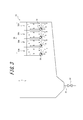
- FIG. 2 is an explanatory view showing a state of a water flow in the sedimentation basin shown in FIG. 1 when the filter medium layer of the filtration unit is washed, in a cross section taken along line AA in FIG.
- FIG. 2 shows the mode of the water flow at the time of wash
- FIG. 2 shows the mode of the water flow at the time of wash
- the sedimentation basin of this invention is not specifically limited, For example, it can be used as a final sedimentation basin provided in the back
- the treated water flow path 4 through which the treated water obtained by filtering the treated water in the filtering unit 3 and the filter medium layer 35 provided in the filtering unit 3 are washed in the filtering unit 3 of the sedimentation tank 1.
- a cleaning drainage channel (not shown) through which the discharged cleaning drainage flows is provided.
- the to-be-processed water which precipitated some solid content in the sedimentation part 2 is further filtered in the filtration part 3, and the treated water from which solid content was fully removed can be obtained.
- the part located under the filtration part 3 also functions as the precipitation part 2 which precipitates the solid content in to-be-processed water.
- the sedimentation unit 2 is not particularly limited, and includes a cross-flow type precipitation tank that separates the solid content from the water to be treated by sedimenting the solid content in the water to be treated by gravity sedimentation.
- a solid content discharge pipe 21 having a solid content discharge valve 22 is provided at the bottom of the sedimentation unit 2.
- the solid content precipitated in the sedimentation section 2 is obtained by always opening a solid content discharge valve 22 provided in the solid content discharge pipe 21 at a predetermined opening, for example, or by opening it every predetermined time. It is discharged from and processed.
- the sedimentation part 2 may be equipped with the inclination board which accelerates
- the filtration part 3 consists of a filtration tank which filters the to-be-processed water which settled a part of solid content in the precipitation part 2 by an upward flow. And as shown to Fig.1 (a) and (b), the filtration part 3 is provided over the side wall located up and down in Fig.1 (a) of the sedimentation basin 1, and the depth of the sedimentation basin 1 is shown. A plurality of (four in the illustrated example) to-be-treated water flow paths 30 are provided that are partitioned by a plurality of (four in the illustrated example) partition walls 31 extending in the vertical direction (the vertical direction in FIG. 1B). . In the sedimentation basin 1, the upper side of the lower end of the partition wall 31 is the filtration unit 3. In addition, the length (the length of the left-right direction in FIG. 1 (a) and (b)) of the filtration part 3 is not specifically limited, It is 1/4 or more and 3/4 or less of the full length of the sedimentation tank 1. be able to.
- each water channel 30 to be treated is a region surrounded by the partition wall 31 and the wall surface of the sedimentation basin 1, and the water to be treated is passed through each water channel 30 to be treated in an upward direction.
- each to-be-processed water flow path 30 is below the filter medium layer 35, the filter medium layer 35 which consists of several filter media with which the process water flow path 30 was filled, the upper screen 33 provided above the filter medium layer 35, and the filter medium layer 35.
- the lower screen 34 provided, and the treated water outflow part 32 from which the treated water obtained by filtering to-be-treated water with the filter material layer 35 flow out to the treated water flow path 4 are provided.
- each of the water channels 30 to be treated includes a gas outlet 36 of an aeration pipe (not shown) used when stirring and washing the filter medium layer 35 using a swirling flow generated by aeration, and a lower side of the gas outlet 36. And a horizontal plate 37 provided on the side.
- Each partition wall 31 extends in a direction along the depth direction (vertical direction) of the sedimentation tank 1.
- Each partition wall 31 is provided so as to be separated from the bottom surface of the sedimentation basin 1, and the treated water flow path 30 and the sedimentation part 2 communicate with each other at the lower part of the sedimentation basin 1. Further, in the depth direction of the sedimentation basin 1, the upper end of each partition wall 31 is positioned above the water surface, and the lower end of each partition wall 31 is positioned below the gas outlet 36.
- the partition 31 is not specifically limited, It can form using a partition plate or a concrete wall.
- the treated water outflow part 32 is a part where treated water overflows from the treated water flow path 30 to the treated water flow path 4, and is located above the upper screen 33 in the example shown in FIG. 1.
- the upper screen 33 prevents the filter medium constituting the filter medium layer 35 from flowing out of the treated water channel 30.
- the lower screen 34 prevents the filter medium constituting the filter medium layer 35 from dropping or flowing out from the treated water flow path 30 downward. Specifically, the lower screen 34 prevents the filter medium from falling downward when the filter medium constituting the filter medium layer is filled in the water channel 30 to be treated, or the solid content precipitated in the precipitation unit 2 is solidified. The filter medium is prevented from flowing out of the water channel 30 to be treated due to the downward flow generated when discharged through the distribution pipe 21.
- the upper screen 33 and the lower screen 34 are not particularly limited as long as the screen has a pore diameter smaller than that of the filter medium constituting the filter medium layer 35, and known screens such as punching metal and wire mesh can be used. .
- the filter medium layer 35 provided between the upper screen 33 and the lower screen 34 is formed by, for example, filling a plurality of filter media constituting the filter medium layer 35 on the lower screen 34 in the water channel 30 to be treated.
- the filter medium constituting the filter medium layer 35 is not particularly limited, and for example, a resin filter medium can be used.
- a filter medium although the filter medium of arbitrary shapes can be used, it is preferable to use a cylindrical filter medium.
- the filter medium layer 35 is configured using a cylindrical filter medium, when the water to be treated passes through the hollow portions of the cylindrical filter medium filled randomly and the gaps between the filter media, each cylindrical filter medium or between the filter mediums This is because the solids in the water to be treated are separated better by the filter medium layer 35 by functioning as a slanted plate settling device with a small gap.
- any of a settling filter medium that is, a filter medium that settles in stationary water to be treated
- a floating filter medium that is, a filter medium that floats in stationary water to be treated
- the filter medium which has the specific gravity of the grade which floats in the water flow of to-be-processed water, and it is more preferable to use the floating filter medium whose specific gravity is less than 1.0.
- the filter medium can be filled into the treated water flow path 30 by putting the filter medium in a state where water is stored in the treated water flow path 30, so that the lower screen 34 may not be provided.
- the aeration pipe having the gas ejection port 36 is connected to an air supply source such as a blower (not shown) provided outside the treated water flow path 30.
- the aeration pipe and the blower having the gas ejection port 36 function as an aeration apparatus that stirs and cleans the filter medium layer 35 using a swirling flow generated by aeration of air as a gas.
- an air pipe valve (not shown) is provided at a connection portion between the aeration pipe and the blower to prevent the water to be treated from flowing backward during filtration.
- the gas jet nozzle 36 is located above the lower end of the partition 31 which divides the filtration part 3 and forms the said to-be-processed water flow path 30. ing. Further, the gas ejection port 36 is treated in the sedimentation basin 1 rather than in the center of each treated water channel 30 when viewed in the length direction of the sedimentation basin 1 (left and right directions in FIGS. 1A and 1B). It is provided on the water inlet side (left side in FIG. 1B).
- the horizontal plate 37 provided in the lower side of the gas jet nozzle 36 is extended in the direction along a horizontal direction, The lower side of the gas ejection port 36 is covered without blocking the entire surface.
- the horizontal plate 37 covers the lower side of the gas outlet 36 provided on the inflow side of the water to be treated to the sedimentation basin 1 from the center of the water channel 30 to be treated.
- one end is connected to the lower end of the partition wall 31 on the inlet side of the water to be treated into the sedimentation basin 1.
- cleaning of the filter medium layer 35 are implemented as follows.
- the cleaning of the filter medium layer 35 is not particularly limited and can be performed, for example, when a predetermined time has elapsed.
- the water pipe valve provided at the connection portion between the aeration pipe and the blower is closed, and the water to be treated is passed through the water flow path 30 in the upward direction while the blower is stopped.
- the clean treated water obtained by filtering the treated water with the filter medium layer 35 provided in the treated water flow path 30 passes through the treated water outflow part 32 and the treated water flow path 4 (for example, treated water tank). Etc.).
- the sedimentation basin 1 provided with the precipitation part 2 and the filtration part 3 mentioned above, since the to-be-processed water which settled a part of solid content in the precipitation part 2 can be further filtered in the filtration part 3, it is solid.
- the treated water from which the minutes have been sufficiently removed can be obtained.
- the air piping valve provided in the connection part of an aeration pipe and a blower is opened, and the to-be-treated water as a wash water flows upward into each to-be-treated water flow path 30 in the state which operated the blower. Then, the filter medium layer 35 is stirred and washed. Then, in the filtration unit 3 that is cleaning the filter medium layer 35, a swirl flow is generated by the air supplied from the gas outlet 36 into each treated water flow path 30 via the blower and the aeration pipe, thereby forming the filter medium layer 35. The filter medium that flows is dispersed.
- the blower and the aeration pipe having the gas ejection port 36 function as an aeration device that agitates the filter medium layer 35 by aeration.
- the solid content captured by the filter medium layer 35 is removed from the filter medium layer 35.
- the washing waste water containing the solid content removed from the filter medium layer 35 is sent to the outside (for example, a washing waste water treatment apparatus or the like) through a washing drain passage (not shown).
- the partition wall 31 is provided to partition the filtration unit 3 into a plurality of water channels 30 to be treated, and aeration is performed from the gas jets 36 provided in each water channel 30 to be treated.
- a high-speed and powerful swirl flow can be easily generated in each treated water channel 30. Therefore, in the sedimentation basin 1, the filter medium constituting the filter medium layer 35 can be sufficiently flowed by the high-speed and powerful swirl flow, and the filter medium layer 35 can be efficiently washed.
- the position of the gas jet port 36 is set at the lower end of the partition wall 31. If the position is lower than that, the sediment rises in the sedimentation part 2 due to the occurrence of a short circuit current or the like, and the sedimentation function itself of the sedimentation part 2 may be lost.
- the state of the water flow when the filter medium layer is washed in the sedimentation basin 1 ⁇ / b> B in which the gas ejection port 36 is disposed below the lower end of the partition wall 31 is indicated by an arrow.
- the gas outlet 36 When the gas outlet 36 is disposed below the lower end, when a swirling flow indicated by arrows b, c, d, e is generated in the treated water flow path 30B by aeration, a part of the water flow b is The resulting water stream a acquires water from a direction of 180 degrees.
- the flow rate of the treated water flowing into the settling basin and the flow rate of the treated water flowing out of the settling basin are equal to each other, which is the difference between the water flow a and the water flow f.
- the size of the water stream b is also constant.
- the size of the water stream b is the sum of the water stream a and the water stream e
- the water stream e that is turned from the water stream d when the water stream a becomes large.
- the size is negligibly small compared to the size of the water stream b. Therefore, the swirl flow indicated by arrows b, c, d, and e cannot be formed.
- the difference between the water flow a and the water flow f is constant under the condition that the amount of water to be treated is constant, the water flow f increases when the water flow a is large.
- the water exchange between the precipitation part 2 and the filtration part 3 becomes intense, thereby causing the already precipitated solid content to rise so that the precipitation function itself of the precipitation part 2 is lost.
- the gas ejection port 36 is provided above the lower end of the partition wall 31, as shown by arrows in FIG. 2, the water flow a Does not acquire water from the direction of 180 degrees, and the size of the water flow a is small (approximately equal to the inflow amount of the water to be treated into the settling basin 1).
- the size of the water flow e turned from the water flow d increases, and the swirl flow indicated by the arrows b, c, d, and e is well formed.
- the difference between the water flow a and the water flow f is constant under the condition that the amount of water to be treated is constant, the water flow f becomes small when the water flow a is small.
- water exchange between the precipitation part 2 and the filtration part 3 is greatly suppressed, so that the precipitation in the precipitation part 2 can be prevented from rising, while suppressing a decrease in the precipitation function of the precipitation part 2, Efficient cleaning of the filtration unit 3 by the swirling flow can be realized.
- the gas jet nozzle 36 is provided in the inflow side of the to-be-treated water to the sedimentation basin 1 rather than the center of the to-be-treated water flow path 30, Then, even if the gas jet port is provided on the side opposite to the inlet side of the water to be treated into the settling basin 1 from the center of the water channel to be treated, it is powerful at high speed while suppressing the deterioration of the function of the precipitation part 2.
- the filtering unit 3 can be efficiently cleaned by a simple swirling flow.
- the gas outlet when the gas outlet is provided on the side opposite to the inlet side of the water to be treated to the settling basin 1 from the center of the water channel to be treated, the downward water flow f flows to the settling basin 1. Since the position of the gas jet 36 and the upward water flow a is away from the inlet of the water to be treated into the settling basin 1, It is possible to prevent the sediment from flying up at the portion located on the inlet side of the water to be treated. Further, from the viewpoint of causing a swirling flow in the filtration unit, the gas outlet 36 is located on the inlet side of the water to be treated to the settling basin 1 or on the side opposite to the inlet side rather than the center of the water passage 30 to be treated.
- the horizontal distance from the partition wall 31 on the inlet side of the water to be treated to the sedimentation basin 1 or the side opposite to the inlet side is within 1 ⁇ 4 or less of the interval between the adjacent partition walls 31. More preferably, it is provided along the partition wall 31.
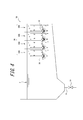
- the sedimentation basin of the present invention it is not necessary to provide the horizontal plate 37 below each gas outlet 36 as in the sedimentation basin 1A shown in FIG. 3, but in the sedimentation basin 1 shown in FIG. 1 and FIG. Since the horizontal plate 37 is provided below each gas jet 36, the state of the water flow when the filter medium layer is washed is compared with the sedimentation basin 1A indicated by the arrow in FIG. In addition, the filtration unit 3 can be efficiently washed by a stronger and faster swirling flow. Specifically, in the sedimentation basin 1A not provided with the horizontal plate 37 as shown in FIG. 3, the water flow a that is a part of the water flow b acquires water from a direction of 90 degrees.
- the size of the water flow a is larger than that of the settling basin 1 shown in FIGS. 1 and 2, and as a result, the size of the water flow e turned from the water flow d is smaller than that of the settling basin 1 shown in FIGS. Become. Further, since the difference between the water flow a and the water flow f is constant under the condition that the amount of water to be treated is constant, the water flow f increases when the water flow a is large. As a result, in the sedimentation basin 1A not provided with the horizontal plate 37 as shown in FIG. 3, the water exchange between the sedimentation unit 2 and the filtration unit 3 is larger than that in the sedimentation basin 1 shown in FIG. 1 and FIG. There is a risk that the already precipitated solid content will rise.
- the sedimentation basin 1 provided with the horizontal plate 37 since the horizontal plate 37 functions like a baffle plate as shown in FIG. 2 in the state of the water flow when the filter medium layer is washed, the sedimentation basin shown in FIG. Compared with 1A, the magnitude of the water stream e turned from the water stream d increases, and the flow velocity of the swirling flow indicated by the arrows b, c, d, e increases, while the water stream a decreases.
- the sedimentation basin 1 provided with the horizontal plate 37 the water exchange between the sedimentation part 2 and the filtration part 3 can be greatly suppressed, and the precipitation of the sediment in the sedimentation part 2 can be prevented. Efficient cleaning of the filtration unit 3 by the swirl flow can be realized while suppressing a decrease in the precipitation function of the unit 2.
- the sedimentation basin of this invention was demonstrated using an example, the sedimentation basin of this invention is not limited to the said example, A change can be suitably added to the sedimentation basin of this invention.
- the position of the gas ejection port 36 is set to one place in each treated water flow path 30.
- you may provide an exit in several positions.
- the horizontal plate 37 is provided integrally with the partition wall 31 at the lower end of the partition wall 31.
- the installation position and installation method of the horizontal plate 37 are As long as the lower side can be covered, any installation position and installation method can be adopted.
- the thickness of the filter medium layer 35 in a state where the water to be treated is not filtered is preferably, for example, 500 mm or more, and 900 mm or less. It is preferable that the thickness is 700 mm or less.
- the depth of the sedimentation basin 1 between the upper screen 33 and the lower screen 34 is preferably 200 mm or more larger than the thickness of the filter medium layer 35.
- the arrangement interval of the partition walls 31 is preferably 2000 mm or less, more preferably 1000 mm or less, and 500 mm or less. More preferably.
- the gas outlet 36 is preferably positioned 70 mm or more above the lower end of the partition wall 31. That is, the distance in the depth direction of the sedimentation basin 1 between the gas jet 36 and the lower end of the partition wall 31 is preferably 70 mm or more. Furthermore, the distance is more preferably 100 mm or more. Furthermore, from the viewpoint of forming a swirling flow over a wide range when the filter medium layer 35 is washed and causing the filter medium to flow well, the gas ejection port 36 is positioned below the lower end of the filter medium layer 35. It is more preferable that the distance from the lower end of the filter medium layer 35 is in the range of 170 mm or more and 300 mm or less when viewed in the depth direction of the sedimentation tank 1.
- the amount of aeration from the gas outlet 36 in each treated water flow path 30 is 10 Nm 3 / hour / m 2 or more. It is preferable to set it to 12 Nm 3 / hour / m 2 or more, and it is preferable to set it to 14 Nm 3 / hour / m 2 or less.
- Example 1 Using the sedimentation basin 1A shown in FIG. 3 (a sedimentation basin having the same configuration as the sedimentation basin 1 shown in FIG. 1 except that the horizontal plate 37 is not provided), the filter medium layer was washed under the following conditions. The presence / absence of roll-up of the precipitate from the precipitation portion and the difference in the size of the head loss in the filtration portion before and after washing (before washing and after washing) were evaluated and measured. The results are shown in Table 1. In addition, the detailed specification of the used sedimentation basin 1A is as follows. Moreover, the presence or absence of winding-up of a precipitate was evaluated visually.
- a sedimentation basin including a sedimentation part and a filtration part, and capable of efficiently washing the filtration part while suppressing a decrease in the function of the sedimentation part.
Abstract
This settling tank is provided with a settling section for precipitating solids in water that is being treated, and a filtering section for filtering water that is being treated and has passed through the settling section with an upward flow. The filtering section is provided with multiple flow channels for the water being treated that are formed by partition walls that extend in the depth direction of the settling tank. The flow channels for the water being treated are provided with a filter material layer, an upper screen provided above the filter material layer, a treated water outflow part out of which the filtered water flows, and a gas-jetting port for stirring the filter material layer using aeration when cleaning the filter material layer.
Description
本発明は、沈殿池に関し、特に、下水処理場の最終沈殿池などとして好適に使用し得る沈殿池に関するものである。
The present invention relates to a sedimentation basin, and more particularly to a sedimentation basin that can be suitably used as a final sedimentation basin for a sewage treatment plant.
従来、下水処理場などでは、最初沈殿池、生物反応槽および最終沈殿池を備える水処理システムが用いられている。
Conventionally, in a sewage treatment plant, a water treatment system including a first sedimentation basin, a biological reaction tank, and a final sedimentation basin is used.
ここで、近年、最初沈殿池や最終沈殿池などの沈殿池として、被処理水中の固形分を沈殿させる沈殿部と、沈殿部で固形分の一部を沈殿させた被処理水をろ過するろ過部とを備える沈殿池を用いることが提案されている。この沈殿部およびろ過部を備える沈殿池によれば、沈殿部において固形分の一部を沈殿させた被処理水をろ過部において更にろ過することができるので、固形分が十分に除去された処理水を得ることができる。
そして、当該沈殿池のろ過部としては、複数のろ材よりなるろ材層と、ろ材層の上方に配設されてろ材層を構成するろ材の流出を防止する上部スクリーンと、ろ材層の下方に配設されてろ材層を構成するろ材を支持する下部スクリーンとを有し、被処理水をろ材層に上向流で通水させることによりろ過を行うろ過部が用いられている(特開平8-257585号、国際公開第2012/161339号)。 Here, in recent years, as a sedimentation basin such as a first sedimentation basin or a final sedimentation basin, a filtration part for precipitating solids in the water to be treated and a filtration for filtering the water to be treated in which a part of the solids is precipitated in the precipitation part It has been proposed to use a sedimentation basin with a part. According to the sedimentation basin provided with this precipitation part and the filtration part, since the to-be-processed water which precipitated some solid content in the precipitation part can be further filtered in a filtration part, the process from which solid content was fully removed You can get water.
The filtration section of the sedimentation basin includes a filter medium layer composed of a plurality of filter media, an upper screen disposed above the filter media layer to prevent the filter media from flowing out, and disposed below the filter media layer. And a lower screen that supports the filter medium that constitutes the filter medium layer, and uses a filtration unit that performs filtration by allowing the water to be treated to flow through the filter medium layer in an upward flow (Japanese Patent Laid-Open No. Hei 8- 257585, International Publication No. 2012/161339).
ここで、ろ過部を備える上記従来の沈殿池では、通常、所定時間毎に、或いは、ろ過部の固液分離性能が低下した際にろ過部のろ材層の洗浄を実施する。そして、ろ材層の洗浄は、通常、ろ過部内に空気等の気体を噴き込み、気体の噴き込みにより生じる水流によってろ材層を構成するろ材を流動させることにより行う。
Here, in the conventional sedimentation basin provided with the filtration unit, the filter medium layer of the filtration unit is usually washed every predetermined time or when the solid-liquid separation performance of the filtration unit is deteriorated. The filter medium layer is usually washed by injecting a gas such as air into the filtration unit and causing the filter medium constituting the filter medium layer to flow by the water flow generated by the gas injection.
しかし、上記従来の沈殿池には、ろ過部内に気体を噴出させた際に十分に高速な水流を発生させることができず、ろ材を十分に流動させることができないという点において改善の余地があった。そのため、従来の沈殿池には、ろ材層の洗浄時に高速な水流を発生させて洗浄効率を高めることが求められていた。
However, the conventional sedimentation basin described above has room for improvement in that a sufficiently high speed water flow cannot be generated when gas is ejected into the filtration section, and the filter medium cannot be sufficiently flowed. It was. Therefore, the conventional sedimentation basin has been required to increase the washing efficiency by generating a high-speed water flow when washing the filter medium layer.
一方、上記従来の沈殿池は、ろ過部のみならず沈殿部も備えている。そのため、上記従来の沈殿池には、ろ材層の洗浄時にろ過部において高速な水流を発生させて洗浄効率を高める一方で、ろ材層の洗浄時に発生する水流によって沈殿部の機能が損なわれないことも求められている。具体的には、沈殿池には、ろ材層の洗浄時に発生する水流に起因して沈殿部側に短絡流等が発生し、沈殿物が舞い上がるのを抑制することも求められている。
On the other hand, the conventional sedimentation basin includes not only a filtration part but also a precipitation part. For this reason, in the conventional sedimentation basin, a high-speed water flow is generated in the filtration part during the cleaning of the filter medium layer to increase the cleaning efficiency, while the function of the precipitation part is not impaired by the water flow generated during the cleaning of the filter medium layer. Is also sought. Specifically, the sedimentation basin is also required to suppress the occurrence of a short circuit flow or the like on the sedimentation portion side due to the water flow generated when the filter medium layer is washed, and the sediment soaring.
そこで、本発明は、沈殿部およびろ過部を備える沈殿池であって、沈殿部の機能の低下を抑制しつつろ過部を効率的に洗浄することが可能な沈殿池を提供することを目的とする。
Then, this invention aims at providing a sedimentation basin provided with a sedimentation part and a filtration part, Comprising: The sedimentation basin which can wash | clean a filtration part efficiently, suppressing the fall of the function of a sedimentation part. To do.
この発明は、上記課題を有利に解決することを目的とするものであり、本発明の沈殿池は、被処理水中の固形分を沈殿させる沈殿部と、前記沈殿部を通過した被処理水を上向流でろ過するろ過部とを備える沈殿池であって、前記ろ過部は、沈殿池の深さ方向に延在する隔壁によって区画形成された複数の被処理水流路を備え、前記被処理水流路は、複数のろ材よりなるろ材層と、前記ろ材層の上方に設けられて前記ろ材の流出を防止する上部スクリーンと、前記ろ材層で被処理水をろ過して得た処理水が流出する処理水流出部と、前記ろ材層を洗浄する際に曝気により前記ろ材層を撹拌するための気体噴出口とを備え、沈殿池の深さ方向において、前記気体噴出口が、前記被処理水流路を区画形成する前記隔壁の下端よりも上側に位置することを特徴とする。このように、ろ過部に複数の被処理水流路を設ければ、ろ材層を洗浄する際に、隔壁によって区画された各被処理水流路において気体噴出口からの曝気により強力な旋回流を発生させ、ろ材層を効率的に洗浄することができる。また、各被処理水流路において、気体噴出口の位置を当該被処理水流路を形成する隔壁の下端の位置よりも上側にすれば、ろ材層の洗浄時に被処理水流路内で強力な旋回流を発生させた場合であっても、沈殿部において沈殿物が舞い上がるのを抑制し、沈殿部の機能の低下を抑制することができる。
ここで、本発明において、「沈殿池の深さ方向に延在する」とは、沈殿池の深さ方向に向かって延びていることを指し、「沈殿池の深さ方向に延在する」には、沈殿池の深さ方向に沿う方向(通常は鉛直方向)に延在している場合に加え、沈殿池の深さ方向に沿う方向に対して傾斜して延在している場合も含まれる。 This invention aims to solve the above-mentioned problem advantageously, and the sedimentation basin of the present invention comprises a precipitation part for precipitating solids in the water to be treated, and water to be treated that has passed through the precipitation part. A sedimentation basin comprising a filtration part for filtering in an upward flow, wherein the filtration part comprises a plurality of treated water flow paths formed by partition walls extending in the depth direction of the sedimentation basin, The water flow path includes a filter medium layer composed of a plurality of filter media, an upper screen provided above the filter media layer to prevent the filter media from flowing out, and treated water obtained by filtering the water to be treated through the filter media layer. And a gas jet for stirring the filter medium layer by aeration when washing the filter medium layer, and in the depth direction of the settling basin, the gas jet is the water flow to be treated. It is located above the lower end of the partition that defines the path. The features. In this way, if a plurality of water channels to be treated are provided in the filtration unit, a strong swirling flow is generated by aeration from the gas outlet in each water channel to be treated partitioned by the partition wall when the filter medium layer is washed. And the filter medium layer can be efficiently washed. Further, if the position of the gas outlet is set above the lower end position of the partition wall forming the treated water flow path in each treated water flow path, a strong swirl flow is generated in the treated water flow path when the filter medium layer is washed. Even if it generates, it can suppress that a sediment rises in a sedimentation part, and can suppress the fall of the function of a sedimentation part.
Here, in the present invention, “extends in the depth direction of the sedimentation basin” means extending in the depth direction of the sedimentation basin, and “extends in the depth direction of the sedimentation basin”. In addition to the case of extending in the direction along the depth direction of the sedimentation basin (usually the vertical direction), the case of extending in the direction along the depth direction of the sedimentation basin included.
ここで、本発明の沈殿池は、沈殿池の深さ方向において、前記気体噴出口が、前記被処理水流路を区画形成する前記隔壁の下端よりも70mm以上上側に位置することが好ましい。気体噴出口と隔壁の下端との間の沈殿池の深さ方向に沿う距離が70mm以上であれば、沈殿部において沈殿物が舞い上がるのを更に抑制し、沈殿部の機能の低下を十分に抑制することができるからである。
Here, in the sedimentation basin of the present invention, in the depth direction of the sedimentation basin, it is preferable that the gas outlet is located 70 mm or more above the lower end of the partition wall that defines the treated water flow path. If the distance along the depth direction of the sedimentation basin between the gas outlet and the lower end of the partition wall is 70 mm or more, it further suppresses the rise of sediment in the sedimentation part, and sufficiently suppresses the deterioration of the function of the sedimentation part. Because it can be done.
また、本発明の沈殿池は、沈殿池の深さ方向において、前記気体噴出口が、前記ろ材層の下端よりも下側に位置することが好ましい。気体噴出口がろ材層の下端よりも下側に位置していれば、ろ材層を構成するろ材を気体噴出口からの曝気により更に良好に流動させ、ろ材層を更に効率的に洗浄することができるからである。
ここで、本発明において、「ろ材層の下端」とは、被処理水のろ過を実施していない状態のろ材層の下端を指す。 In the sedimentation basin of the present invention, it is preferable that the gas outlet is located below the lower end of the filter medium layer in the depth direction of the sedimentation basin. If the gas outlet is located below the lower end of the filter medium layer, the filter medium constituting the filter medium layer can be flowed more satisfactorily by aeration from the gas outlet, and the filter medium layer can be washed more efficiently. Because it can.
Here, in the present invention, the “lower end of the filter medium layer” refers to the lower end of the filter medium layer in a state where the water to be treated is not filtered.
そして、本発明の沈殿池は、前記被処理水流路は、水平方向に延在する横板を前記気体噴出口の下側に更に備えることが好ましい。このように、気体噴出口の下側に横板を設ければ、ろ材層の洗浄時に沈殿部において沈殿物が舞い上がるのを更に抑制し、沈殿部の機能の低下を十分に抑制することができるからである。
ここで、本発明において、「水平方向に延在する」とは、水平方向に向かって延びていることを指し、「水平方向に延在する」には、水平方向に沿う方向に延在している場合に加え、水平方向に沿う方向に対して傾斜して延在している場合も含まれる。 And as for the sedimentation basin of this invention, it is preferable that the said to-be-processed water flow path is further equipped with the horizontal plate extended in the horizontal direction under the said gas jet nozzle. Thus, if a horizontal plate is provided on the lower side of the gas ejection port, it is possible to further suppress the rise of the precipitate in the precipitation portion during the cleaning of the filter medium layer, and to sufficiently suppress the deterioration of the function of the precipitation portion. Because.
Here, in the present invention, “extending in the horizontal direction” means extending in the horizontal direction, and “extending in the horizontal direction” extends in a direction along the horizontal direction. In addition to the case where it extends, the case where it inclines with respect to the direction along a horizontal direction is included.
本発明の沈殿池によれば、沈殿部の機能の低下を抑制しつつろ過部を効率的に洗浄することができる。
According to the sedimentation basin of the present invention, the filtration part can be efficiently washed while suppressing the deterioration of the function of the precipitation part.
以下、本発明の実施の形態を、図面に基づき詳細に説明する。なお、各図において、同一の符号を付したものは、同一の構成要素を示すものとする。
Hereinafter, embodiments of the present invention will be described in detail with reference to the drawings. In addition, in each figure, what attached | subjected the same code | symbol shall show the same component.
(沈殿池)
ここで、本発明の沈殿池は、特に限定されることなく、例えば下水処理場において生物反応槽の後段側に設けられる最終沈殿池として用いることができる。そして、本発明の沈殿池の一例は、例えば図1に示すような概略構成を有している。 (Settling pond)
Here, the sedimentation basin of this invention is not specifically limited, For example, it can be used as a final sedimentation basin provided in the back | latter stage side of a biological reaction tank in a sewage treatment plant. And an example of the sedimentation basin of this invention has schematic structure as shown, for example in FIG.
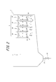
具体的には、図1(a)に平面図を示し、図1(b)に図1(a)のA-A線に沿う断面図を示すように、本発明の一例の沈殿池1は、被処理水中の固形分を沈殿させる沈殿部2と、沈殿部2の後段側に設けられて沈殿部2を通過した被処理水を上向流でろ過するろ過部3とを備えている。また、沈殿池1のろ過部3には、ろ過部3で被処理水をろ過して得た処理水が流れる処理水流路4と、ろ過部3に設けられたろ材層35を洗浄した際に排出される洗浄排水が流れる洗浄排水流路(図示せず)とが設けられている。そして、沈殿池1では、沈殿部2において固形分の一部を沈殿させた被処理水をろ過部3において更にろ過することにより、固形分が十分に除去された処理水を得ることができる。
なお、沈殿池1においては、ろ過部3の下側に位置する部分も被処理水中の固形分を沈殿させる沈殿部2として機能する。 Specifically, as shown in FIG. 1 (a), a plan view, and in FIG. 1 (b), a sectional view taken along the line AA in FIG. Theprecipitating part 2 for precipitating solids in the water to be treated and the filtering part 3 provided on the rear side of the precipitating part 2 and filtering the water to be treated that has passed through the precipitating part 2 in an upward flow. Further, when the treated water flow path 4 through which the treated water obtained by filtering the treated water in the filtering unit 3 and the filter medium layer 35 provided in the filtering unit 3 are washed in the filtering unit 3 of the sedimentation tank 1. A cleaning drainage channel (not shown) through which the discharged cleaning drainage flows is provided. And in the sedimentation basin 1, the to-be-processed water which precipitated some solid content in the sedimentation part 2 is further filtered in the filtration part 3, and the treated water from which solid content was fully removed can be obtained.
In addition, in the sedimentation basin 1, the part located under thefiltration part 3 also functions as the precipitation part 2 which precipitates the solid content in to-be-processed water.
なお、沈殿池1においては、ろ過部3の下側に位置する部分も被処理水中の固形分を沈殿させる沈殿部2として機能する。 Specifically, as shown in FIG. 1 (a), a plan view, and in FIG. 1 (b), a sectional view taken along the line AA in FIG. The
In addition, in the sedimentation basin 1, the part located under the
<沈殿部>
ここで、沈殿部2は、特に限定されることなく、被処理水中の固形分を重力沈降により沈降させて被処理水から固形分を分離する横流式沈殿槽よりなる。そして、沈殿部2の底部には、固形分排出弁22を有する固形分排出配管21が設けられている。沈殿部2で沈殿した固形分は、固形分排出配管21に設けられた固形分排出弁22を、例えば所定の開度で常時開いておく、或いは、所定時間毎に開くことにより、沈殿池1から排出されて処理される。
なお、沈殿部2は、固形分の沈降を促進する傾斜板や、底部に沈殿した固形分を掻き寄せる往復式掻寄機などを備えていてもよい。 <Precipitation part>
Here, thesedimentation unit 2 is not particularly limited, and includes a cross-flow type precipitation tank that separates the solid content from the water to be treated by sedimenting the solid content in the water to be treated by gravity sedimentation. A solid content discharge pipe 21 having a solid content discharge valve 22 is provided at the bottom of the sedimentation unit 2. The solid content precipitated in the sedimentation section 2 is obtained by always opening a solid content discharge valve 22 provided in the solid content discharge pipe 21 at a predetermined opening, for example, or by opening it every predetermined time. It is discharged from and processed.
In addition, thesedimentation part 2 may be equipped with the inclination board which accelerates | stimulates sedimentation of solid content, the reciprocating type scraper which scrapes the solid content settled on the bottom part, etc.
ここで、沈殿部2は、特に限定されることなく、被処理水中の固形分を重力沈降により沈降させて被処理水から固形分を分離する横流式沈殿槽よりなる。そして、沈殿部2の底部には、固形分排出弁22を有する固形分排出配管21が設けられている。沈殿部2で沈殿した固形分は、固形分排出配管21に設けられた固形分排出弁22を、例えば所定の開度で常時開いておく、或いは、所定時間毎に開くことにより、沈殿池1から排出されて処理される。
なお、沈殿部2は、固形分の沈降を促進する傾斜板や、底部に沈殿した固形分を掻き寄せる往復式掻寄機などを備えていてもよい。 <Precipitation part>
Here, the
In addition, the
<ろ過部>
ろ過部3は、沈殿部2において固形分の一部を沈殿させた被処理水を上向流でろ過するろ過槽よりなる。そして、ろ過部3は、図1(a)および(b)に示すように、沈殿池1の図1(a)では上下に位置する側壁間に亘って設けられ、且つ、沈殿池1の深さ方向(図1(b)では上下方向)に延在する複数(図示例では4枚)の隔壁31によって区画形成された複数(図示例では4つ)の被処理水流路30を備えている。そして、沈殿池1では隔壁31の下端よりも上側がろ過部3となる。
なお、ろ過部3の長さ(図1(a)および(b)では左右方向の長さ)は、特に限定されることなく、沈殿池1の全長の1/4以上3/4以下とすることができる。 <Filtration part>
Thefiltration part 3 consists of a filtration tank which filters the to-be-processed water which settled a part of solid content in the precipitation part 2 by an upward flow. And as shown to Fig.1 (a) and (b), the filtration part 3 is provided over the side wall located up and down in Fig.1 (a) of the sedimentation basin 1, and the depth of the sedimentation basin 1 is shown. A plurality of (four in the illustrated example) to-be-treated water flow paths 30 are provided that are partitioned by a plurality of (four in the illustrated example) partition walls 31 extending in the vertical direction (the vertical direction in FIG. 1B). . In the sedimentation basin 1, the upper side of the lower end of the partition wall 31 is the filtration unit 3.
In addition, the length (the length of the left-right direction in FIG. 1 (a) and (b)) of thefiltration part 3 is not specifically limited, It is 1/4 or more and 3/4 or less of the full length of the sedimentation tank 1. be able to.
ろ過部3は、沈殿部2において固形分の一部を沈殿させた被処理水を上向流でろ過するろ過槽よりなる。そして、ろ過部3は、図1(a)および(b)に示すように、沈殿池1の図1(a)では上下に位置する側壁間に亘って設けられ、且つ、沈殿池1の深さ方向(図1(b)では上下方向)に延在する複数(図示例では4枚)の隔壁31によって区画形成された複数(図示例では4つ)の被処理水流路30を備えている。そして、沈殿池1では隔壁31の下端よりも上側がろ過部3となる。
なお、ろ過部3の長さ(図1(a)および(b)では左右方向の長さ)は、特に限定されることなく、沈殿池1の全長の1/4以上3/4以下とすることができる。 <Filtration part>
The
In addition, the length (the length of the left-right direction in FIG. 1 (a) and (b)) of the
ここで、各被処理水流路30は、隔壁31と沈殿池1の壁面とによって囲まれた領域であり、被処理水は、各被処理水流路30に上向流で通水される。そして、各被処理水流路30は、被処理水流路30内に充填された複数のろ材よりなるろ材層35と、ろ材層35の上方に設けられた上部スクリーン33と、ろ材層35の下方に設けられた下部スクリーン34と、ろ材層35で被処理水をろ過して得た処理水が処理水流路4へと流出する処理水流出部32とを備えている。更に、各被処理水流路30は、曝気により生じる旋回流を用いてろ材層35を撹拌洗浄する際に使用する曝気管(図示せず)の気体噴出口36と、気体噴出口36の下側に設けられた横板37とを備えている。
Here, each water channel 30 to be treated is a region surrounded by the partition wall 31 and the wall surface of the sedimentation basin 1, and the water to be treated is passed through each water channel 30 to be treated in an upward direction. And each to-be-processed water flow path 30 is below the filter medium layer 35, the filter medium layer 35 which consists of several filter media with which the process water flow path 30 was filled, the upper screen 33 provided above the filter medium layer 35, and the filter medium layer 35. The lower screen 34 provided, and the treated water outflow part 32 from which the treated water obtained by filtering to-be-treated water with the filter material layer 35 flow out to the treated water flow path 4 are provided. Further, each of the water channels 30 to be treated includes a gas outlet 36 of an aeration pipe (not shown) used when stirring and washing the filter medium layer 35 using a swirling flow generated by aeration, and a lower side of the gas outlet 36. And a horizontal plate 37 provided on the side.
各隔壁31は、沈殿池1の深さ方向(鉛直方向)に沿う方向に延在している。そして、各隔壁31は、沈殿池1の底面から離隔させて設けられており、被処理水流路30と沈殿部2とは沈殿池1の下部で連通している。また、沈殿池1の深さ方向において、各隔壁31の上端は水面よりも上側に位置しており、各隔壁31の下端は気体噴出口36よりも下側に位置している。
なお、隔壁31は、特に限定されることなく、仕切り板やコンクリート壁を用いて形成することができる。 Eachpartition wall 31 extends in a direction along the depth direction (vertical direction) of the sedimentation tank 1. Each partition wall 31 is provided so as to be separated from the bottom surface of the sedimentation basin 1, and the treated water flow path 30 and the sedimentation part 2 communicate with each other at the lower part of the sedimentation basin 1. Further, in the depth direction of the sedimentation basin 1, the upper end of each partition wall 31 is positioned above the water surface, and the lower end of each partition wall 31 is positioned below the gas outlet 36.
In addition, thepartition 31 is not specifically limited, It can form using a partition plate or a concrete wall.
なお、隔壁31は、特に限定されることなく、仕切り板やコンクリート壁を用いて形成することができる。 Each
In addition, the
処理水流出部32は、処理水が被処理水流路30内から処理水流路4へと越流する部分であり、図1に示す例では、上部スクリーン33よりも上側に位置している。
The treated water outflow part 32 is a part where treated water overflows from the treated water flow path 30 to the treated water flow path 4, and is located above the upper screen 33 in the example shown in FIG. 1.
上部スクリーン33は、ろ材層35を構成するろ材が被処理水流路30から流出するのを防止する。また、下部スクリーン34は、ろ材層35を構成するろ材が被処理水流路30内から下方へと落下または流出するのを防止する。具体的には、下部スクリーン34は、ろ材層を構成するろ材を被処理水流路30内に充填する際にろ材が下方に落下するのを防止したり、沈殿部2において沈殿した固形分を固形分排出配管21を介して排出する際に生じる下向流によりろ材が被処理水流路30内から流出するのを防止したりする。
なお、上部スクリーン33および下部スクリーン34としては、ろ材層35を構成するろ材よりも孔径が小さいスクリーンであれば特に限定されることなく、パンチングメタルや金網などの既知のスクリーンを使用することができる。 Theupper screen 33 prevents the filter medium constituting the filter medium layer 35 from flowing out of the treated water channel 30. The lower screen 34 prevents the filter medium constituting the filter medium layer 35 from dropping or flowing out from the treated water flow path 30 downward. Specifically, the lower screen 34 prevents the filter medium from falling downward when the filter medium constituting the filter medium layer is filled in the water channel 30 to be treated, or the solid content precipitated in the precipitation unit 2 is solidified. The filter medium is prevented from flowing out of the water channel 30 to be treated due to the downward flow generated when discharged through the distribution pipe 21.
Theupper screen 33 and the lower screen 34 are not particularly limited as long as the screen has a pore diameter smaller than that of the filter medium constituting the filter medium layer 35, and known screens such as punching metal and wire mesh can be used. .
なお、上部スクリーン33および下部スクリーン34としては、ろ材層35を構成するろ材よりも孔径が小さいスクリーンであれば特に限定されることなく、パンチングメタルや金網などの既知のスクリーンを使用することができる。 The
The
上部スクリーン33と下部スクリーン34との間に設けられたろ材層35は、例えばろ材層35を構成する複数のろ材を被処理水流路30内の下部スクリーン34上に充填して形成されている。
ここで、ろ材層35を構成するろ材としては、特に限定されることなく、例えば樹脂製のろ材を用いることができる。そして、ろ材としては、任意の形状のろ材を用いることができるが、筒状のろ材を用いることが好ましい。筒状のろ材を用いてろ材層35を構成した場合、ランダムに充填された筒状のろ材の中空部およびろ材間の隙間を被処理水が通過する際に、各筒状のろ材やろ材間の隙間が小さな傾斜板沈殿装置のように機能して被処理水中の固形分がろ材層35でより良好に分離されるからである。また、ろ材としては、沈降性ろ材(即ち、静止した被処理水中で沈降するろ材)と、浮上ろ材(即ち、静止した被処理水中で浮くろ材)との何れを用いてもよいが、図1(b)に示すように、被処理水の通水中には浮く程度の比重を有するろ材を用いることが好ましく、比重が1.0未満の浮上ろ材を用いることがより好ましい。なお、ろ材として浮上ろ材を使用する場合には、被処理水流路30内に水を貯留した状態でろ材を投入することにより被処理水流路30内にろ材を充填することができるので、下部スクリーン34は設けなくてもよい。 Thefilter medium layer 35 provided between the upper screen 33 and the lower screen 34 is formed by, for example, filling a plurality of filter media constituting the filter medium layer 35 on the lower screen 34 in the water channel 30 to be treated.
Here, the filter medium constituting thefilter medium layer 35 is not particularly limited, and for example, a resin filter medium can be used. And as a filter medium, although the filter medium of arbitrary shapes can be used, it is preferable to use a cylindrical filter medium. When the filter medium layer 35 is configured using a cylindrical filter medium, when the water to be treated passes through the hollow portions of the cylindrical filter medium filled randomly and the gaps between the filter media, each cylindrical filter medium or between the filter mediums This is because the solids in the water to be treated are separated better by the filter medium layer 35 by functioning as a slanted plate settling device with a small gap. In addition, as the filter medium, any of a settling filter medium (that is, a filter medium that settles in stationary water to be treated) and a floating filter medium (that is, a filter medium that floats in stationary water to be treated) may be used. As shown to (b), it is preferable to use the filter medium which has the specific gravity of the grade which floats in the water flow of to-be-processed water, and it is more preferable to use the floating filter medium whose specific gravity is less than 1.0. When a floating filter medium is used as the filter medium, the filter medium can be filled into the treated water flow path 30 by putting the filter medium in a state where water is stored in the treated water flow path 30, so that the lower screen 34 may not be provided.
ここで、ろ材層35を構成するろ材としては、特に限定されることなく、例えば樹脂製のろ材を用いることができる。そして、ろ材としては、任意の形状のろ材を用いることができるが、筒状のろ材を用いることが好ましい。筒状のろ材を用いてろ材層35を構成した場合、ランダムに充填された筒状のろ材の中空部およびろ材間の隙間を被処理水が通過する際に、各筒状のろ材やろ材間の隙間が小さな傾斜板沈殿装置のように機能して被処理水中の固形分がろ材層35でより良好に分離されるからである。また、ろ材としては、沈降性ろ材(即ち、静止した被処理水中で沈降するろ材)と、浮上ろ材(即ち、静止した被処理水中で浮くろ材)との何れを用いてもよいが、図1(b)に示すように、被処理水の通水中には浮く程度の比重を有するろ材を用いることが好ましく、比重が1.0未満の浮上ろ材を用いることがより好ましい。なお、ろ材として浮上ろ材を使用する場合には、被処理水流路30内に水を貯留した状態でろ材を投入することにより被処理水流路30内にろ材を充填することができるので、下部スクリーン34は設けなくてもよい。 The
Here, the filter medium constituting the
気体噴出口36を有する曝気管は、被処理水流路30外に設けられたブロア(図示せず)等の空気供給源に接続されている。そして、気体噴出口36を有する曝気管とブロアとは、気体としての空気の曝気により生じる旋回流を用いてろ材層35を撹拌洗浄する曝気装置として機能する。なお、曝気管とブロアとの接続部には、ろ過中に被処理水が逆流するのを防止するための空気配管弁(図示せず)が設けられている。
The aeration pipe having the gas ejection port 36 is connected to an air supply source such as a blower (not shown) provided outside the treated water flow path 30. The aeration pipe and the blower having the gas ejection port 36 function as an aeration apparatus that stirs and cleans the filter medium layer 35 using a swirling flow generated by aeration of air as a gas. Note that an air pipe valve (not shown) is provided at a connection portion between the aeration pipe and the blower to prevent the water to be treated from flowing backward during filtration.
そして、沈殿池1のろ過部3の各被処理水流路30では、気体噴出口36は、ろ過部3を区画して当該被処理水流路30を形成する隔壁31の下端よりも上側に位置している。また、気体噴出口36は、沈殿池1の長さ方向(図1(a)および(b)では左右方向)に見て、各被処理水流路30の中央よりも沈殿池1への被処理水の流入口側(図1(b)では左側)に設けられている。
And in each to-be-processed water flow path 30 of the filtration part 3 of the sedimentation basin 1, the gas jet nozzle 36 is located above the lower end of the partition 31 which divides the filtration part 3 and forms the said to-be-processed water flow path 30. ing. Further, the gas ejection port 36 is treated in the sedimentation basin 1 rather than in the center of each treated water channel 30 when viewed in the length direction of the sedimentation basin 1 (left and right directions in FIGS. 1A and 1B). It is provided on the water inlet side (left side in FIG. 1B).
また、各被処理水流路30では、気体噴出口36の下側に設けられた横板37は、水平方向に沿う方向に延在しており、被処理水流路30の下側の開口部の全面を塞ぐことなく気体噴出口36の下側を覆っている。具体的には、沈殿池1では、横板37は、被処理水流路30の中央よりも沈殿池1への被処理水の流入口側に設けられている気体噴出口36の下側を覆うように、一端を沈殿池1への被処理水の流入口側の隔壁31の下端に接続させて設けられている。
Moreover, in each to-be-processed water flow path 30, the horizontal plate 37 provided in the lower side of the gas jet nozzle 36 is extended in the direction along a horizontal direction, The lower side of the gas ejection port 36 is covered without blocking the entire surface. Specifically, in the sedimentation basin 1, the horizontal plate 37 covers the lower side of the gas outlet 36 provided on the inflow side of the water to be treated to the sedimentation basin 1 from the center of the water channel 30 to be treated. As described above, one end is connected to the lower end of the partition wall 31 on the inlet side of the water to be treated into the sedimentation basin 1.
そして、上述した構成を有する沈殿池1のろ過部3では、以下のようにして被処理水のろ過およびろ材層35の洗浄が実施される。なお、ろ材層35の洗浄は、特に限定されることなく、例えば予め定めた所定の時間が経過した際に実施することができる。
And in the filtration part 3 of the sedimentation basin 1 which has the structure mentioned above, filtration of to-be-processed water and the washing | cleaning of the filter medium layer 35 are implemented as follows. The cleaning of the filter medium layer 35 is not particularly limited and can be performed, for example, when a predetermined time has elapsed.
即ち、沈殿池1では、曝気管とブロアとの接続部に設けられた空気配管弁を閉じ、ブロアを停止させた状態で被処理水を被処理水流路30に上向流で通水することにより、被処理水をろ過する。そして、被処理水流路30内に設けられたろ材層35で被処理水をろ過して得た清浄な処理水は、処理水流出部32および処理水流路4を介して外部(例えば、処理水槽など)へと送水される。
That is, in the sedimentation basin 1, the water pipe valve provided at the connection portion between the aeration pipe and the blower is closed, and the water to be treated is passed through the water flow path 30 in the upward direction while the blower is stopped. To filter the water to be treated. The clean treated water obtained by filtering the treated water with the filter medium layer 35 provided in the treated water flow path 30 passes through the treated water outflow part 32 and the treated water flow path 4 (for example, treated water tank). Etc.).
従って、上述した沈殿部2およびろ過部3を備える沈殿池1によれば、沈殿部2において固形分の一部を沈殿させた被処理水をろ過部3において更にろ過することができるので、固形分が十分に除去された処理水を得ることができる。
Therefore, according to the sedimentation basin 1 provided with the precipitation part 2 and the filtration part 3 mentioned above, since the to-be-processed water which settled a part of solid content in the precipitation part 2 can be further filtered in the filtration part 3, it is solid. The treated water from which the minutes have been sufficiently removed can be obtained.
また、沈殿池1では、曝気管とブロアとの接続部に設けられた空気配管弁を開き、ブロアを運転させた状態で洗浄水としての被処理水を各被処理水流路30に上向流で通水することにより、ろ材層35を撹拌洗浄する。そして、ろ材層35を洗浄中のろ過部3では、ブロアおよび曝気管を介して気体噴出口36から各被処理水流路30内に供給された空気により旋回流が発生し、ろ材層35を構成するろ材が流動して分散する。即ち、ろ過部3では、ブロアと、気体噴出口36を有する曝気管とが曝気によりろ材層35を撹拌する曝気装置として機能する。その結果、ろ過部3では、ろ材層35に捕捉されていた固形分がろ材層35から除去される。なお、ろ材層35から除去された固形分を含む洗浄排水は、洗浄排水流路(図示せず)を介して外部(例えば、洗浄排水処理装置など)へと送水される。
Moreover, in the sedimentation basin 1, the air piping valve provided in the connection part of an aeration pipe and a blower is opened, and the to-be-treated water as a wash water flows upward into each to-be-treated water flow path 30 in the state which operated the blower. Then, the filter medium layer 35 is stirred and washed. Then, in the filtration unit 3 that is cleaning the filter medium layer 35, a swirl flow is generated by the air supplied from the gas outlet 36 into each treated water flow path 30 via the blower and the aeration pipe, thereby forming the filter medium layer 35. The filter medium that flows is dispersed. That is, in the filtration unit 3, the blower and the aeration pipe having the gas ejection port 36 function as an aeration device that agitates the filter medium layer 35 by aeration. As a result, in the filtration unit 3, the solid content captured by the filter medium layer 35 is removed from the filter medium layer 35. In addition, the washing waste water containing the solid content removed from the filter medium layer 35 is sent to the outside (for example, a washing waste water treatment apparatus or the like) through a washing drain passage (not shown).
ここで、隔壁31を設けてろ過部3を複数の被処理水流路30に区画しない場合には、広いろ過部3に対して曝気により強力な旋回流を起こすことは困難である。しかし、上述した沈殿池1では、隔壁31を設けてろ過部3を複数の被処理水流路30に区画し、各被処理水流路30に設けられた気体噴出口36から曝気しているので、各被処理水流路30内に高速で強力な旋回流を容易に発生させることができる。従って、沈殿池1では、高速で強力な旋回流によってろ材層35を構成するろ材を十分に流動させ、ろ材層35を効率的に洗浄することができる。その結果、ろ材層35の洗浄に要する時間を短時間化し、また、ろ材層35の洗浄時に排出する洗浄排水の量を低減することができるので、処理水の回収率(=(得られた処理水量/沈殿池に流入した被処理水量)×100%)も高めることができる。
Here, when the partition wall 31 is provided and the filtration unit 3 is not partitioned into a plurality of water channels 30 to be treated, it is difficult to cause a strong swirl flow by aeration with respect to the wide filtration unit 3. However, in the sedimentation basin 1 described above, the partition wall 31 is provided to partition the filtration unit 3 into a plurality of water channels 30 to be treated, and aeration is performed from the gas jets 36 provided in each water channel 30 to be treated. A high-speed and powerful swirl flow can be easily generated in each treated water channel 30. Therefore, in the sedimentation basin 1, the filter medium constituting the filter medium layer 35 can be sufficiently flowed by the high-speed and powerful swirl flow, and the filter medium layer 35 can be efficiently washed. As a result, the time required for cleaning the filter medium layer 35 can be shortened, and the amount of cleaning wastewater discharged during the cleaning of the filter medium layer 35 can be reduced, so that the recovery rate of treated water (= (obtained treatment It is also possible to increase the amount of water / the amount of treated water that has flowed into the settling basin) × 100%).
また、隔壁31によりろ過部3を区画して形成した被処理水流路30毎に気体噴出口36を設けて高速で強力な旋回流を発生させる場合、気体噴出口36の位置を隔壁31の下端よりも下側にすると、短絡流などの発生により沈殿部2において沈殿物が舞い上がり、沈殿部2の沈殿機能自体も失われる虞がある。具体的には、例えば図4に隔壁31の下端よりも下側に気体噴出口36を配設した沈殿池1Bにおいてろ材層を洗浄した際の水流の様子を矢印で示すように、隔壁31の下端よりも下側に気体噴出口36を配設すると、曝気により矢印b,c,d,eで示される旋回流を被処理水流路30B内に発生させた際に、水流bの一部となる水流aは180度の方向から水を獲得する。ここで、沈殿池へ流入する被処理水の流量および沈殿池から流出する処理水の流量は互いに等しく、水流aと水流fとの差になる。また、曝気量が一定であれば水流bの大きさも一定となるところ、水流bの大きさは水流aと水流eの和であるから、水流aが大きくなれば水流dから転じられる水流eの大きさは水流bの大きさに比べて無視できるほどに小さくなる。そのため、矢印b,c,d,eで示される旋回流はほぼ形成できない。それに対して、被処理水量が一定の条件下では水流aと水流fとの差は一定なので、水流aが大きいと、水流fも大きくなる。つまり、沈殿部2とろ過部3との間の水交換が激しくなり、それによって、すでに沈殿した固形分の舞い上がりが激しく生じて、沈殿部2の沈殿機能自体も失われる。
しかし、上述した沈殿池1では、隔壁31の下端よりも上側に気体噴出口36を設けているので、ろ材層35を洗浄した際の水流の様子を図2に矢印で示すように、水流aが180度の方向から水を獲得することがなく、水流aの大きさは小さく(沈殿池1への被処理水の流入量にほぼ等しく)なる。その結果、水流dから転じられる水流eの大きさが大きくなり、矢印b,c,d,eで示される旋回流が良好に形成される。また、被処理水量が一定の条件下では水流aと水流fとの差は一定なので、水流aが小さいと、水流fも小さくなる。その結果、沈殿部2とろ過部3との間の水交換が大幅に抑えられ、沈殿部2における沈殿物の舞い上がりを防止することができ、沈殿部2の沈殿機能の低下を抑制しつつ、旋回流による効率なろ過部3の洗浄を実現できる。 In addition, when agas jet 36 is provided for each treated water flow path 30 formed by partitioning the filtration unit 3 with the partition wall 31 to generate a strong swirling flow at high speed, the position of the gas jet port 36 is set at the lower end of the partition wall 31. If the position is lower than that, the sediment rises in the sedimentation part 2 due to the occurrence of a short circuit current or the like, and the sedimentation function itself of the sedimentation part 2 may be lost. Specifically, for example, as shown by arrows in FIG. 4, the state of the water flow when the filter medium layer is washed in the sedimentation basin 1 </ b> B in which the gas ejection port 36 is disposed below the lower end of the partition wall 31 is indicated by an arrow. When the gas outlet 36 is disposed below the lower end, when a swirling flow indicated by arrows b, c, d, e is generated in the treated water flow path 30B by aeration, a part of the water flow b is The resulting water stream a acquires water from a direction of 180 degrees. Here, the flow rate of the treated water flowing into the settling basin and the flow rate of the treated water flowing out of the settling basin are equal to each other, which is the difference between the water flow a and the water flow f. Further, when the aeration amount is constant, the size of the water stream b is also constant. However, since the size of the water stream b is the sum of the water stream a and the water stream e, the water stream e that is turned from the water stream d when the water stream a becomes large. The size is negligibly small compared to the size of the water stream b. Therefore, the swirl flow indicated by arrows b, c, d, and e cannot be formed. On the other hand, since the difference between the water flow a and the water flow f is constant under the condition that the amount of water to be treated is constant, the water flow f increases when the water flow a is large. That is, the water exchange between the precipitation part 2 and the filtration part 3 becomes intense, thereby causing the already precipitated solid content to rise so that the precipitation function itself of the precipitation part 2 is lost.
However, in the sedimentation basin 1 described above, since thegas ejection port 36 is provided above the lower end of the partition wall 31, as shown by arrows in FIG. 2, the water flow a Does not acquire water from the direction of 180 degrees, and the size of the water flow a is small (approximately equal to the inflow amount of the water to be treated into the settling basin 1). As a result, the size of the water flow e turned from the water flow d increases, and the swirl flow indicated by the arrows b, c, d, and e is well formed. Further, since the difference between the water flow a and the water flow f is constant under the condition that the amount of water to be treated is constant, the water flow f becomes small when the water flow a is small. As a result, water exchange between the precipitation part 2 and the filtration part 3 is greatly suppressed, so that the precipitation in the precipitation part 2 can be prevented from rising, while suppressing a decrease in the precipitation function of the precipitation part 2, Efficient cleaning of the filtration unit 3 by the swirling flow can be realized.
しかし、上述した沈殿池1では、隔壁31の下端よりも上側に気体噴出口36を設けているので、ろ材層35を洗浄した際の水流の様子を図2に矢印で示すように、水流aが180度の方向から水を獲得することがなく、水流aの大きさは小さく(沈殿池1への被処理水の流入量にほぼ等しく)なる。その結果、水流dから転じられる水流eの大きさが大きくなり、矢印b,c,d,eで示される旋回流が良好に形成される。また、被処理水量が一定の条件下では水流aと水流fとの差は一定なので、水流aが小さいと、水流fも小さくなる。その結果、沈殿部2とろ過部3との間の水交換が大幅に抑えられ、沈殿部2における沈殿物の舞い上がりを防止することができ、沈殿部2の沈殿機能の低下を抑制しつつ、旋回流による効率なろ過部3の洗浄を実現できる。 In addition, when a
However, in the sedimentation basin 1 described above, since the
なお、図1および2に示す沈殿池1では、気体噴出口36を被処理水流路30の中央よりも沈殿池1への被処理水の流入口側に設けているが、本発明の沈殿池では、気体噴出口を被処理水流路の中央よりも沈殿池1への被処理水の流入口側とは反対側に設けても、沈殿部2の機能の低下を抑制しつつ、高速で強力な旋回流によってろ過部3を効率的に洗浄することができる。具体的には、気体噴出口を被処理水流路の中央よりも沈殿池1への被処理水の流入口側とは反対側に設けた場合には、下方への水流fが沈殿池1への被処理水の流入口側に位置すると共に気体噴出口36および上方への水流aの位置が沈殿池1への被処理水の流入口から離れるので、沈殿部2のうちの沈殿池1への被処理水の流入口側に位置する部分における沈殿物の舞い上がりを防止することができる。また、ろ過部にて旋回流を起こすためという観点からは、気体噴出口36は、被処理水流路30の中央よりも沈殿池1への被処理水の流入口側あるいは流入口側と反対側に設けることが好ましく、沈殿池1への被処理水の流入口側あるいは流入口側と反対側の隔壁31からの水平方向の距離が隣接する隔壁31間の間隔の1/4以下の範囲内に設けることがより好ましく、隔壁31に沿わせて設けることが好ましい。
In addition, in the sedimentation basin 1 shown to FIG. 1 and 2, although the gas jet nozzle 36 is provided in the inflow side of the to-be-treated water to the sedimentation basin 1 rather than the center of the to-be-treated water flow path 30, Then, even if the gas jet port is provided on the side opposite to the inlet side of the water to be treated into the settling basin 1 from the center of the water channel to be treated, it is powerful at high speed while suppressing the deterioration of the function of the precipitation part 2. The filtering unit 3 can be efficiently cleaned by a simple swirling flow. Specifically, when the gas outlet is provided on the side opposite to the inlet side of the water to be treated to the settling basin 1 from the center of the water channel to be treated, the downward water flow f flows to the settling basin 1. Since the position of the gas jet 36 and the upward water flow a is away from the inlet of the water to be treated into the settling basin 1, It is possible to prevent the sediment from flying up at the portion located on the inlet side of the water to be treated. Further, from the viewpoint of causing a swirling flow in the filtration unit, the gas outlet 36 is located on the inlet side of the water to be treated to the settling basin 1 or on the side opposite to the inlet side rather than the center of the water passage 30 to be treated. Preferably, the horizontal distance from the partition wall 31 on the inlet side of the water to be treated to the sedimentation basin 1 or the side opposite to the inlet side is within ¼ or less of the interval between the adjacent partition walls 31. More preferably, it is provided along the partition wall 31.
更に、本発明の沈殿池では、図3に示す沈殿池1Aのように各気体噴出口36の下側に横板37を設けなくてもよいが、図1および図2に示す沈殿池1では、各気体噴出口36の下側に横板37を設けているので、ろ材層を洗浄した際の水流の様子を図3に矢印で示す沈殿池1Aと比較し、沈殿物の舞い上がりを更に抑制することができると共に、より強力で高速な旋回流によってろ過部3を効率的に洗浄することができる。具体的には、図3に示すような横板37を設けていない沈殿池1Aでは、水流bの一部となる水流aは90度の方向から水を獲得する。そのため、水流aの大きさは図1および図2に示す沈殿池1よりも大きくなり、その結果、水流dから転じられる水流eの大きさが図1および図2に示す沈殿池1よりも小さくなる。また、被処理水量が一定の条件下では水流aと水流fとの差は一定なので、水流aが大きいと、水流fも大きくなる。その結果、図3に示すような横板37を設けていない沈殿池1Aでは、沈殿部2とろ過部3との間の水交換が図1および図2に示す沈殿池1よりも大きくなり、すでに沈殿した固形分の舞い上がりが生じる虞がある。一方、横板37を設けた沈殿池1では、ろ材層を洗浄した際の水流の様子を図2に示すように、横板37が邪魔板のように機能するため、図3に示す沈殿池1Aと比較して、水流dから転じられる水流eの大きさが大きくなり、矢印b,c,d,eで示される旋回流の流速が早くなる一方で水流aが小さくなる。その結果、横板37を設けた沈殿池1では、沈殿部2とろ過部3との間の水交換が大幅に抑えられ、沈殿部2における沈殿物の舞い上がりを防止することができるので、沈殿部2の沈殿機能の低下を抑制しつつ、旋回流による効率なろ過部3の洗浄を実現できる。
Furthermore, in the sedimentation basin of the present invention, it is not necessary to provide the horizontal plate 37 below each gas outlet 36 as in the sedimentation basin 1A shown in FIG. 3, but in the sedimentation basin 1 shown in FIG. 1 and FIG. Since the horizontal plate 37 is provided below each gas jet 36, the state of the water flow when the filter medium layer is washed is compared with the sedimentation basin 1A indicated by the arrow in FIG. In addition, the filtration unit 3 can be efficiently washed by a stronger and faster swirling flow. Specifically, in the sedimentation basin 1A not provided with the horizontal plate 37 as shown in FIG. 3, the water flow a that is a part of the water flow b acquires water from a direction of 90 degrees. Therefore, the size of the water flow a is larger than that of the settling basin 1 shown in FIGS. 1 and 2, and as a result, the size of the water flow e turned from the water flow d is smaller than that of the settling basin 1 shown in FIGS. Become. Further, since the difference between the water flow a and the water flow f is constant under the condition that the amount of water to be treated is constant, the water flow f increases when the water flow a is large. As a result, in the sedimentation basin 1A not provided with the horizontal plate 37 as shown in FIG. 3, the water exchange between the sedimentation unit 2 and the filtration unit 3 is larger than that in the sedimentation basin 1 shown in FIG. 1 and FIG. There is a risk that the already precipitated solid content will rise. On the other hand, in the sedimentation basin 1 provided with the horizontal plate 37, since the horizontal plate 37 functions like a baffle plate as shown in FIG. 2 in the state of the water flow when the filter medium layer is washed, the sedimentation basin shown in FIG. Compared with 1A, the magnitude of the water stream e turned from the water stream d increases, and the flow velocity of the swirling flow indicated by the arrows b, c, d, e increases, while the water stream a decreases. As a result, in the sedimentation basin 1 provided with the horizontal plate 37, the water exchange between the sedimentation part 2 and the filtration part 3 can be greatly suppressed, and the precipitation of the sediment in the sedimentation part 2 can be prevented. Efficient cleaning of the filtration unit 3 by the swirl flow can be realized while suppressing a decrease in the precipitation function of the unit 2.
以上、一例を用いて本発明の沈殿池について説明したが、本発明の沈殿池は、上記一例に限定されることはなく、本発明の沈殿池には、適宜変更を加えることができる。
As mentioned above, although the sedimentation basin of this invention was demonstrated using an example, the sedimentation basin of this invention is not limited to the said example, A change can be suitably added to the sedimentation basin of this invention.
具体的には、上記一例の沈殿池1では各被処理水流路30内において気体噴出口36の位置を一箇所としたが、本発明の沈殿池では、旋回流を発生させることができれば気体噴出口は複数の位置に設けてもよい。
Specifically, in the sedimentation basin 1 of the above example, the position of the gas ejection port 36 is set to one place in each treated water flow path 30. However, in the sedimentation basin of the present invention, if the swirl flow can be generated, You may provide an exit in several positions.
また、上記一例の沈殿池1では横板37を隔壁31の下端に隔壁31と一体的に設けたが、本発明の沈殿池では、横板37の設置位置および設置方法は、気体噴出口の下側を覆うことができれば任意の設置位置および設置方法とすることができる。
Moreover, in the sedimentation basin 1 of the above example, the horizontal plate 37 is provided integrally with the partition wall 31 at the lower end of the partition wall 31. However, in the sedimentation basin of the present invention, the installation position and installation method of the horizontal plate 37 are As long as the lower side can be covered, any installation position and installation method can be adopted.
更に、旋回流によりろ材層35を効率的に洗浄する観点からは、被処理水のろ過を実施していない状態のろ材層35の厚みは、例えば500mm以上とすることが好ましく、900mm以下とすることが好ましく、700mm以下とすることがさらに好ましい。
Furthermore, from the viewpoint of efficiently washing the filter medium layer 35 with a swirl flow, the thickness of the filter medium layer 35 in a state where the water to be treated is not filtered is preferably, for example, 500 mm or more, and 900 mm or less. It is preferable that the thickness is 700 mm or less.
また、ろ材層35を洗浄する際にろ材が流動するスペースを十分に確保してろ材層35を効率的に洗浄する観点からは、上部スクリーン33と下部スクリーン34との間の沈殿池1の深さ方向の距離は、ろ材層35の厚みよりも200mm以上大きいことが好ましい。
Further, from the viewpoint of efficiently washing the filter medium layer 35 by securing a sufficient space for the filter medium to flow when the filter medium layer 35 is washed, the depth of the sedimentation basin 1 between the upper screen 33 and the lower screen 34. The distance in the vertical direction is preferably 200 mm or more larger than the thickness of the filter medium layer 35.
更に、各被処理水流路30内に高速で強力な旋回流を発生させる観点からは、隔壁31の配設間隔は、2000mm以下とすることが好ましく、1000mm以下とすることがより好ましく、500mm以下とすることがさらに好ましい。
Furthermore, from the viewpoint of generating a high-speed and powerful swirl flow in each treated water flow path 30, the arrangement interval of the partition walls 31 is preferably 2000 mm or less, more preferably 1000 mm or less, and 500 mm or less. More preferably.
また、沈殿物の舞い上がりを十分に抑制する観点からは、気体噴出口36は、隔壁31の下端よりも70mm以上上側に位置させることが好ましい。即ち、気体噴出口36と隔壁31の下端との間の沈殿池1の深さ方向の距離は70mm以上であることが好ましい。更に言えば、かかる距離は、100mm以上であることがさらに好ましい。更に、ろ材層35を洗浄する際に広い範囲に亘って旋回流を形成してろ材を良好に流動させる観点からは、気体噴出口36は、ろ材層35の下端よりも下側に位置させることが好ましく、沈殿池1の深さ方向に見て、ろ材層35の下端からの距離が170mm以上300mm以下の範囲内に位置させることがより好ましい。
Further, from the viewpoint of sufficiently suppressing the soaking of the precipitate, the gas outlet 36 is preferably positioned 70 mm or more above the lower end of the partition wall 31. That is, the distance in the depth direction of the sedimentation basin 1 between the gas jet 36 and the lower end of the partition wall 31 is preferably 70 mm or more. Furthermore, the distance is more preferably 100 mm or more. Furthermore, from the viewpoint of forming a swirling flow over a wide range when the filter medium layer 35 is washed and causing the filter medium to flow well, the gas ejection port 36 is positioned below the lower end of the filter medium layer 35. It is more preferable that the distance from the lower end of the filter medium layer 35 is in the range of 170 mm or more and 300 mm or less when viewed in the depth direction of the sedimentation tank 1.
更に、各被処理水流路30内に高速で強力な旋回流を発生させる観点からは、各被処理水流路30内における気体噴出口36からの曝気量は、10Nm3/時間/m2以上とすることが好ましく、12Nm3/時間/m2以上とすることがさらに好ましく、14Nm3/時間/m2以下とすることが好ましい。
Further, from the viewpoint of generating a high-speed and powerful swirl flow in each treated water flow path 30, the amount of aeration from the gas outlet 36 in each treated water flow path 30 is 10 Nm 3 / hour / m 2 or more. It is preferable to set it to 12 Nm 3 / hour / m 2 or more, and it is preferable to set it to 14 Nm 3 / hour / m 2 or less.
以下、本発明について実施例を用いて更に詳細に説明するが、本発明はこれら実施例に限定されるものではない。
Hereinafter, the present invention will be described in more detail using examples, but the present invention is not limited to these examples.
(実施例1)
図3に示す沈殿池1A(横板37を有さない以外は図1に示す沈殿池1と同様の構成を有する沈殿池)を使用し、以下の条件でろ材層の洗浄を実施した際の沈殿部からの沈殿物の巻き上がりの有無および洗浄前後でのろ過部における損失水頭の大きさの差(洗浄前-洗浄後)を評価および測定した。結果を表1に示す。
なお、使用した沈殿池1Aの詳細な仕様は、以下の通りである。また、沈殿物の巻き上がりの有無は、目視により評価した。
・沈殿池の寸法:8m×1.5m×3.7m
・隔壁の配設間隔:500mm
・ろ材層の厚み:700mm
・上部スクリーンと下部スクリーンとの間の距離:900mm
・気体噴出口の位置:隔壁の下端から上方へ100mm
ろ材層の下端から下方へ300mm
被処理水の流入口側の隔壁の位置から右方へ150mm
・被処理水流量:12.4m3/時間
・曝気量:12Nm3/時間/m2
・水面積負荷:25m3/m2/日
・水面積:12m2
・ろ材層の面積:3m2 (Example 1)
Using thesedimentation basin 1A shown in FIG. 3 (a sedimentation basin having the same configuration as the sedimentation basin 1 shown in FIG. 1 except that the horizontal plate 37 is not provided), the filter medium layer was washed under the following conditions. The presence / absence of roll-up of the precipitate from the precipitation portion and the difference in the size of the head loss in the filtration portion before and after washing (before washing and after washing) were evaluated and measured. The results are shown in Table 1.
In addition, the detailed specification of the usedsedimentation basin 1A is as follows. Moreover, the presence or absence of winding-up of a precipitate was evaluated visually.
・ Dimension of sedimentation basin: 8m × 1.5m × 3.7m
・ Distance between partition walls: 500mm
・ Thickness of filter medium layer: 700mm
-Distance between upper screen and lower screen: 900mm
・ Gas outlet position: 100 mm upward from the lower end of the partition
300mm downward from the lower end of the filter media layer
150mm to the right from the position of the partition wall on the inlet side of the water to be treated
・ Flow rate of treated water: 12.4 m 3 / hour ・ Aeration amount: 12 Nm 3 / hour / m 2
・ Water area load: 25m 3 / m 2 / day ・ Water area: 12m 2
・ Area of filter media layer: 3m 2
図3に示す沈殿池1A(横板37を有さない以外は図1に示す沈殿池1と同様の構成を有する沈殿池)を使用し、以下の条件でろ材層の洗浄を実施した際の沈殿部からの沈殿物の巻き上がりの有無および洗浄前後でのろ過部における損失水頭の大きさの差(洗浄前-洗浄後)を評価および測定した。結果を表1に示す。
なお、使用した沈殿池1Aの詳細な仕様は、以下の通りである。また、沈殿物の巻き上がりの有無は、目視により評価した。
・沈殿池の寸法:8m×1.5m×3.7m
・隔壁の配設間隔:500mm
・ろ材層の厚み:700mm
・上部スクリーンと下部スクリーンとの間の距離:900mm
・気体噴出口の位置:隔壁の下端から上方へ100mm
ろ材層の下端から下方へ300mm
被処理水の流入口側の隔壁の位置から右方へ150mm
・被処理水流量:12.4m3/時間
・曝気量:12Nm3/時間/m2
・水面積負荷:25m3/m2/日
・水面積:12m2
・ろ材層の面積:3m2 (Example 1)
Using the
In addition, the detailed specification of the used
・ Dimension of sedimentation basin: 8m × 1.5m × 3.7m
・ Distance between partition walls: 500mm
・ Thickness of filter medium layer: 700mm
-Distance between upper screen and lower screen: 900mm
・ Gas outlet position: 100 mm upward from the lower end of the partition
300mm downward from the lower end of the filter media layer
150mm to the right from the position of the partition wall on the inlet side of the water to be treated
・ Flow rate of treated water: 12.4 m 3 / hour ・ Aeration amount: 12 Nm 3 / hour / m 2
・ Water area load: 25m 3 / m 2 / day ・ Water area: 12m 2
・ Area of filter media layer: 3m 2
(比較例1)
図4に示す沈殿池1B(隔壁31の長さを変更して気体噴出口36を隔壁31の下端よりも下側に設けた沈殿池)を使用し、実施例1と同様にして沈殿部からの沈殿物の巻き上がりの有無および洗浄前後でのろ過部における損失水頭の大きさの差(洗浄前-洗浄後)を評価および測定した。結果を表1に示す。
なお、使用した沈殿池1Bの詳細な仕様は、以下の通りである。
・沈殿池の寸法:8m×1.5m×3.7m
・隔壁の配設間隔:500mm
・ろ材層の厚み:700mm
・上部スクリーンと下部スクリーンとの間の距離:900mm
・気体噴出口の位置:隔壁の下端から下方へ100mm
ろ材層の下端から下方へ300mm
被処理水の流入口側の隔壁の位置から右方へ150mm
・被処理水流量:12.4m3/時間
・曝気量:12Nm3/時間/m2
・水面積負荷:25m3/m2/日
・水面積:12m2
・ろ材層の面積:3m2 (Comparative Example 1)
Using thesedimentation basin 1B shown in FIG. 4 (a sedimentation basin in which the length of the partition wall 31 is changed and the gas ejection port 36 is provided below the lower end of the partition wall 31), And the difference in the size of the head loss in the filtration part before and after washing (before washing and after washing) was evaluated and measured. The results are shown in Table 1.
In addition, the detailed specification of the usedsedimentation basin 1B is as follows.
・ Dimension of sedimentation basin: 8m × 1.5m × 3.7m
・ Distance between partition walls: 500mm
・ Thickness of filter medium layer: 700mm
-Distance between upper screen and lower screen: 900mm
・ Gas outlet position: 100 mm downward from the lower end of the partition
300mm downward from the lower end of the filter media layer
150mm to the right from the position of the partition wall on the inlet side of the water to be treated
・ Flow rate of treated water: 12.4 m 3 / hour ・ Aeration amount: 12 Nm 3 / hour / m 2
・ Water area load: 25m 3 / m 2 / day ・ Water area: 12m 2
・ Area of filter media layer: 3m 2
図4に示す沈殿池1B(隔壁31の長さを変更して気体噴出口36を隔壁31の下端よりも下側に設けた沈殿池)を使用し、実施例1と同様にして沈殿部からの沈殿物の巻き上がりの有無および洗浄前後でのろ過部における損失水頭の大きさの差(洗浄前-洗浄後)を評価および測定した。結果を表1に示す。
なお、使用した沈殿池1Bの詳細な仕様は、以下の通りである。
・沈殿池の寸法:8m×1.5m×3.7m
・隔壁の配設間隔:500mm
・ろ材層の厚み:700mm
・上部スクリーンと下部スクリーンとの間の距離:900mm
・気体噴出口の位置:隔壁の下端から下方へ100mm
ろ材層の下端から下方へ300mm
被処理水の流入口側の隔壁の位置から右方へ150mm
・被処理水流量:12.4m3/時間
・曝気量:12Nm3/時間/m2
・水面積負荷:25m3/m2/日
・水面積:12m2
・ろ材層の面積:3m2 (Comparative Example 1)
Using the
In addition, the detailed specification of the used
・ Dimension of sedimentation basin: 8m × 1.5m × 3.7m
・ Distance between partition walls: 500mm
・ Thickness of filter medium layer: 700mm
-Distance between upper screen and lower screen: 900mm
・ Gas outlet position: 100 mm downward from the lower end of the partition
300mm downward from the lower end of the filter media layer
150mm to the right from the position of the partition wall on the inlet side of the water to be treated
・ Flow rate of treated water: 12.4 m 3 / hour ・ Aeration amount: 12 Nm 3 / hour / m 2
・ Water area load: 25m 3 / m 2 / day ・ Water area: 12m 2
・ Area of filter media layer: 3m 2

表1より、実施例1の沈殿池では、比較例1の沈殿池に比べ、沈殿部の沈殿機能の低下を抑制しつつろ過部を効率的に洗浄することができることが分かる。
From Table 1, it can be seen that in the sedimentation basin of Example 1, the filtration part can be efficiently washed while suppressing a decrease in the sedimentation function of the sedimentation part as compared with the sedimentation basin of Comparative Example 1.
本発明によれば、沈殿部およびろ過部を備える沈殿池であって、沈殿部の機能の低下を抑制しつつろ過部を効率的に洗浄することが可能な沈殿池を提供することができる。
According to the present invention, it is possible to provide a sedimentation basin including a sedimentation part and a filtration part, and capable of efficiently washing the filtration part while suppressing a decrease in the function of the sedimentation part.
Claims (4)
- 被処理水中の固形分を沈殿させる沈殿部と、前記沈殿部を通過した被処理水を上向流でろ過するろ過部とを備える沈殿池であって、
前記ろ過部は、沈殿池の深さ方向に延在する隔壁によって区画形成された複数の被処理水流路を備え、
前記被処理水流路は、複数のろ材よりなるろ材層と、前記ろ材層の上方に設けられて前記ろ材の流出を防止する上部スクリーンと、前記ろ材層で被処理水をろ過して得た処理水が流出する処理水流出部と、前記ろ材層を洗浄する際に曝気により前記ろ材層を撹拌するための気体噴出口とを備え、
沈殿池の深さ方向において、前記気体噴出口が、前記被処理水流路を区画形成する前記隔壁の下端よりも上側に位置することを特徴とする、沈殿池。 A sedimentation basin comprising a precipitation part for precipitating solids in the treated water, and a filtration part for filtering the treated water that has passed through the precipitation part in an upward flow,
The filtration unit includes a plurality of water-to-be-treated flow channels that are partitioned by partition walls extending in the depth direction of the settling basin,
The treated water flow path is obtained by filtering the treated water through the filter medium layer, a filter medium layer made of a plurality of filter media, an upper screen provided above the filter medium layer to prevent the filter medium from flowing out, and the filter medium layer. A treated water outflow part from which water flows out, and a gas jet for stirring the filter medium layer by aeration when washing the filter medium layer,
In the depth direction of the sedimentation basin, the gas ejection port is located above the lower end of the partition wall that partitions the treated water flow path. - 沈殿池の深さ方向において、前記気体噴出口が、前記被処理水流路を区画形成する前記隔壁の下端よりも70mm以上上側に位置することを特徴とする、請求項1に記載の沈殿池。 2. The sedimentation basin according to claim 1, wherein in the depth direction of the sedimentation basin, the gas ejection port is located 70 mm or more above a lower end of the partition wall that defines the treated water flow path.
- 沈殿池の深さ方向において、前記気体噴出口が、前記ろ材層の下端よりも下側に位置することを特徴とする、請求項1または2に記載の沈殿池。 The sedimentation basin according to claim 1 or 2, wherein the gas outlet is located below the lower end of the filter medium layer in the depth direction of the sedimentation basin.
- 前記被処理水流路は、水平方向に延在する横板を前記気体噴出口の下側に更に備える、請求項1~3の何れかに記載の沈殿池。 The sedimentation basin according to any one of claims 1 to 3, wherein the treated water flow path further includes a horizontal plate extending in a horizontal direction below the gas ejection port.
Applications Claiming Priority (2)
| Application Number | Priority Date | Filing Date | Title |
|---|---|---|---|
| JP2015-056328 | 2015-03-19 | ||
| JP2015056328A JP6437857B2 (en) | 2015-03-19 | 2015-03-19 | Sedimentation pond |
Publications (1)
| Publication Number | Publication Date |
|---|---|
| WO2016147229A1 true WO2016147229A1 (en) | 2016-09-22 |
Family
ID=56918529
Family Applications (1)
| Application Number | Title | Priority Date | Filing Date |
|---|---|---|---|
| PCT/JP2015/005288 WO2016147229A1 (en) | 2015-03-19 | 2015-10-20 | Settling tank |
Country Status (2)
| Country | Link |
|---|---|
| JP (1) | JP6437857B2 (en) |
| WO (1) | WO2016147229A1 (en) |
Cited By (1)
| Publication number | Priority date | Publication date | Assignee | Title |
|---|---|---|---|---|
| CN111847690A (en) * | 2020-07-28 | 2020-10-30 | 梁秀宜 | High-efficient sedimentation tank that sewage treatment used |
Families Citing this family (6)
| Publication number | Priority date | Publication date | Assignee | Title |
|---|---|---|---|---|
| JP6830037B2 (en) * | 2017-05-31 | 2021-02-17 | メタウォーター株式会社 | Sewage treatment system |
| JP7030032B2 (en) * | 2018-08-27 | 2022-03-04 | メタウォーター株式会社 | Filtration device |
| JP7064406B2 (en) * | 2018-08-27 | 2022-05-10 | メタウォーター株式会社 | Filtration device |
| JP7064405B2 (en) * | 2018-08-27 | 2022-05-10 | メタウォーター株式会社 | Filtration device |
| WO2021033435A1 (en) * | 2019-08-22 | 2021-02-25 | 積水アクアシステム株式会社 | Solid-liquid separation system |
| JP7311112B2 (en) * | 2019-08-22 | 2023-07-19 | 積水アクアシステム株式会社 | Solid-liquid separation system |
Citations (4)
| Publication number | Priority date | Publication date | Assignee | Title |
|---|---|---|---|---|
| JPH0537303U (en) * | 1991-10-24 | 1993-05-21 | 株式会社西原環境衛生研究所 | High-rate separator that uses raw water as filter medium wash water |
| JPH05301005A (en) * | 1992-04-24 | 1993-11-16 | Hitachi Kiden Kogyo Ltd | Precipitation tank for advanced wastewater treatment |
| JPH11244870A (en) * | 1998-03-05 | 1999-09-14 | Nkk Corp | Flocculating and settling device for sewage and cleaning method thereof |
| WO2012161339A1 (en) * | 2011-05-26 | 2012-11-29 | メタウォーター株式会社 | Sewage treatment system |
-
2015
- 2015-03-19 JP JP2015056328A patent/JP6437857B2/en active Active
- 2015-10-20 WO PCT/JP2015/005288 patent/WO2016147229A1/en active Application Filing
Patent Citations (4)
| Publication number | Priority date | Publication date | Assignee | Title |
|---|---|---|---|---|
| JPH0537303U (en) * | 1991-10-24 | 1993-05-21 | 株式会社西原環境衛生研究所 | High-rate separator that uses raw water as filter medium wash water |
| JPH05301005A (en) * | 1992-04-24 | 1993-11-16 | Hitachi Kiden Kogyo Ltd | Precipitation tank for advanced wastewater treatment |
| JPH11244870A (en) * | 1998-03-05 | 1999-09-14 | Nkk Corp | Flocculating and settling device for sewage and cleaning method thereof |
| WO2012161339A1 (en) * | 2011-05-26 | 2012-11-29 | メタウォーター株式会社 | Sewage treatment system |
Cited By (1)
| Publication number | Priority date | Publication date | Assignee | Title |
|---|---|---|---|---|
| CN111847690A (en) * | 2020-07-28 | 2020-10-30 | 梁秀宜 | High-efficient sedimentation tank that sewage treatment used |
Also Published As
| Publication number | Publication date |
|---|---|
| JP6437857B2 (en) | 2018-12-12 |
| JP2016175009A (en) | 2016-10-06 |
Similar Documents
| Publication | Publication Date | Title |
|---|---|---|
| JP6437857B2 (en) | Sedimentation pond | |
| KR101700931B1 (en) | apparatus for reducing non-point source contaminant having function of screen and filtering media washing | |
| KR101668618B1 (en) | non-point source contaminant treatment apparatus having function of sedimentation and filtering media washing | |
| ES2937166T3 (en) | Multilayer Media Bed Filter with Enhanced Backwash | |
| JP6316156B2 (en) | Sedimentation pond | |
| JP2015525672A (en) | Media bed filter for filtering particulates from a stock stream and method of using the same | |
| JP5259698B2 (en) | Water treatment equipment and method by flotation separation | |
| KR100955098B1 (en) | Treatment apparatus for phosphorus removal from rain water | |
| KR100955909B1 (en) | Treatment apparatus for rain water | |
| KR100894646B1 (en) | Dissolved air floatation tank | |
| JP2599538B2 (en) | Inclined plate type sedimentation tank and method for preventing clogging thereof | |
| JP6496931B2 (en) | Processing fluid treatment system | |
| KR20140093378A (en) | Appatus for wastewater of used coal ash of coal thermo power plant | |
| KR101425770B1 (en) | Lateral-flow type filtering apparatus and first flush stormwater treatment apparatus using it | |
| KR101586628B1 (en) | A sludge separation device for water and sewage and a sludge separation method for water and sewage using the same | |
| JPH0780210A (en) | Cleaning method of inclined plate-type sedimentation tank | |
| KR101603743B1 (en) | Diatomite filter device for send filter | |
| JP3191559B2 (en) | Solid-liquid separation device | |
| KR101889546B1 (en) | Filtering Apparatus Containing Floating Media and Filtering Method | |
| JP3178632U (en) | High speed precipitation filter | |
| JP2006281019A (en) | Water purifying equipment | |
| GB2118452A (en) | Filtration method and apparatus | |
| KR101787078B1 (en) | Filtering Apparatus Containing Floating Media and Filtering Method | |
| JPH0838927A (en) | Apparatus for purification for sand provided with gas inlet part in range of lower side and method for purification using this purification apparatus | |
| KR100894645B1 (en) | Clean water system using dissolved air floatation tank |
Legal Events
| Date | Code | Title | Description |
|---|---|---|---|
| 121 | Ep: the epo has been informed by wipo that ep was designated in this application |
Ref document number: 15885327 Country of ref document: EP Kind code of ref document: A1 |
|
| NENP | Non-entry into the national phase |
Ref country code: DE |
|
| 122 | Ep: pct application non-entry in european phase |
Ref document number: 15885327 Country of ref document: EP Kind code of ref document: A1 |