WO2016143728A1 - 電池状態推定装置 - Google Patents
電池状態推定装置 Download PDFInfo
- Publication number
- WO2016143728A1 WO2016143728A1 PCT/JP2016/056932 JP2016056932W WO2016143728A1 WO 2016143728 A1 WO2016143728 A1 WO 2016143728A1 JP 2016056932 W JP2016056932 W JP 2016056932W WO 2016143728 A1 WO2016143728 A1 WO 2016143728A1
- Authority
- WO
- WIPO (PCT)
- Prior art keywords
- charge transfer
- current
- secondary battery
- value
- battery
- Prior art date
Links
Images


Classifications
-
- G—PHYSICS
- G01—MEASURING; TESTING
- G01R—MEASURING ELECTRIC VARIABLES; MEASURING MAGNETIC VARIABLES
- G01R31/00—Arrangements for testing electric properties; Arrangements for locating electric faults; Arrangements for electrical testing characterised by what is being tested not provided for elsewhere
- G01R31/36—Arrangements for testing, measuring or monitoring the electrical condition of accumulators or electric batteries, e.g. capacity or state of charge [SoC]
- G01R31/367—Software therefor, e.g. for battery testing using modelling or look-up tables
-
- G—PHYSICS
- G01—MEASURING; TESTING
- G01R—MEASURING ELECTRIC VARIABLES; MEASURING MAGNETIC VARIABLES
- G01R31/00—Arrangements for testing electric properties; Arrangements for locating electric faults; Arrangements for electrical testing characterised by what is being tested not provided for elsewhere
- G01R31/36—Arrangements for testing, measuring or monitoring the electrical condition of accumulators or electric batteries, e.g. capacity or state of charge [SoC]
-
- H—ELECTRICITY
- H01—ELECTRIC ELEMENTS
- H01M—PROCESSES OR MEANS, e.g. BATTERIES, FOR THE DIRECT CONVERSION OF CHEMICAL ENERGY INTO ELECTRICAL ENERGY
- H01M10/00—Secondary cells; Manufacture thereof
- H01M10/42—Methods or arrangements for servicing or maintenance of secondary cells or secondary half-cells
- H01M10/4285—Testing apparatus
-
- H—ELECTRICITY
- H01—ELECTRIC ELEMENTS
- H01M—PROCESSES OR MEANS, e.g. BATTERIES, FOR THE DIRECT CONVERSION OF CHEMICAL ENERGY INTO ELECTRICAL ENERGY
- H01M10/00—Secondary cells; Manufacture thereof
- H01M10/42—Methods or arrangements for servicing or maintenance of secondary cells or secondary half-cells
- H01M10/48—Accumulators combined with arrangements for measuring, testing or indicating the condition of cells, e.g. the level or density of the electrolyte
- H01M10/482—Accumulators combined with arrangements for measuring, testing or indicating the condition of cells, e.g. the level or density of the electrolyte for several batteries or cells simultaneously or sequentially
-
- H—ELECTRICITY
- H02—GENERATION; CONVERSION OR DISTRIBUTION OF ELECTRIC POWER
- H02J—CIRCUIT ARRANGEMENTS OR SYSTEMS FOR SUPPLYING OR DISTRIBUTING ELECTRIC POWER; SYSTEMS FOR STORING ELECTRIC ENERGY
- H02J7/00—Circuit arrangements for charging or depolarising batteries or for supplying loads from batteries
-
- G—PHYSICS
- G01—MEASURING; TESTING
- G01R—MEASURING ELECTRIC VARIABLES; MEASURING MAGNETIC VARIABLES
- G01R31/00—Arrangements for testing electric properties; Arrangements for locating electric faults; Arrangements for electrical testing characterised by what is being tested not provided for elsewhere
- G01R31/36—Arrangements for testing, measuring or monitoring the electrical condition of accumulators or electric batteries, e.g. capacity or state of charge [SoC]
- G01R31/389—Measuring internal impedance, internal conductance or related variables
-
- H—ELECTRICITY
- H01—ELECTRIC ELEMENTS
- H01M—PROCESSES OR MEANS, e.g. BATTERIES, FOR THE DIRECT CONVERSION OF CHEMICAL ENERGY INTO ELECTRICAL ENERGY
- H01M2220/00—Batteries for particular applications
- H01M2220/20—Batteries in motive systems, e.g. vehicle, ship, plane
-
- Y—GENERAL TAGGING OF NEW TECHNOLOGICAL DEVELOPMENTS; GENERAL TAGGING OF CROSS-SECTIONAL TECHNOLOGIES SPANNING OVER SEVERAL SECTIONS OF THE IPC; TECHNICAL SUBJECTS COVERED BY FORMER USPC CROSS-REFERENCE ART COLLECTIONS [XRACs] AND DIGESTS
- Y02—TECHNOLOGIES OR APPLICATIONS FOR MITIGATION OR ADAPTATION AGAINST CLIMATE CHANGE
- Y02E—REDUCTION OF GREENHOUSE GAS [GHG] EMISSIONS, RELATED TO ENERGY GENERATION, TRANSMISSION OR DISTRIBUTION
- Y02E60/00—Enabling technologies; Technologies with a potential or indirect contribution to GHG emissions mitigation
- Y02E60/10—Energy storage using batteries
Definitions
- the present invention relates to an apparatus for estimating the state of the secondary battery based on a battery model of the secondary battery.
- Patent Document 1 As an apparatus for estimating the state of the secondary battery, there is an apparatus disclosed in Patent Document 1 below.
- the device disclosed in Patent Document 1 uses an adaptive digital filter to express parameter values representing a battery model of a secondary battery expressed as an equivalent circuit in which one resistor and one RC parallel circuit are connected in series. Estimate all at once. And this apparatus estimates the charging rate of a secondary battery based on the value of each estimated parameter.
- the main purpose of the present invention is to provide a battery state estimation device that can avoid a decrease in accuracy of estimation of the state of the secondary battery even when the temperature of the secondary battery is low.
- the battery state estimation apparatus includes a DC resistance model representing a DC resistance (Rs) of a secondary battery (20a), a model representing a charge transfer impedance of the secondary battery, and a Butler-Volmer formula A charge transfer impedance model including a charge transfer resistance parameter ( ⁇ ) correlated with an exchange current density, and an RC equivalent circuit model including a parallel connection of a resistor and a capacitor, the diffusion of the secondary battery
- the Butler-Volmer based on the amount of change in the detected current value flowing through the secondary battery, the charge transfer impedance model in the battery model of the secondary battery configured by a series connection body of diffusion impedance models representing impedance A first difference between the current flowing through the secondary battery defined by the equation and the potential difference between the charge transfer resistors.
- An updating unit (30) is provided for performing a process of updating the relationship so as to approach a second relationship between the current value that actually flows through the secondary battery and the actual potential difference value of the charge transfer resistance.
- the battery state estimation device further includes a state estimation unit (30) that estimates the state of the secondary battery based on the battery model including the charge transfer impedance model updated by the update unit.
- the internal impedance of a secondary battery can be broadly divided into DC resistance, charge transfer impedance, and diffusion impedance.
- the battery model is a model including a series connection body of a DC resistance model, a charge transfer impedance model, and a diffusion impedance model.
- the charge transfer impedance model is derived from the Butler-Volmer equation in electrochemistry, and represents a non-linear characteristic of the secondary battery.
- this model includes a parameter corresponding to the Butler-Bolmer exchange current density, and includes a charge transfer resistance parameter correlated with the temperature of the secondary battery. Since the charge transfer resistance parameter depends on the temperature of the secondary battery, in the exemplary embodiment of the present invention, for example, the current-voltage nonlinear characteristic at a low temperature that cannot be expressed by the technique described in Patent Document 1 is accurately obtained. Can be represented.
- the charge transfer resistance parameter may change due to deterioration of the secondary battery, may deviate from an appropriate value due to a model error or temperature detection error of the charge transfer impedance model, or may vary depending on individual differences of the secondary battery. Can do. In this case, there is a concern that the estimation accuracy of the state of the secondary battery based on the battery model is lowered.
- the update unit based on the amount of change in the detected current value flowing in the secondary battery, the current flowing in the secondary battery defined by the Butler-Volmer equation and The charge transfer impedance model is updated so that the relationship between the potential difference of the charge transfer resistance approaches the actual relationship between the current flowing through the secondary battery and the potential difference of the charge transfer resistance.
- the relationship between the current flowing through the secondary battery and the potential difference between the charge transfer resistances depends on the charge transfer resistance parameter.
- the update of the charge transfer impedance model by the update unit can suppress the deviation between the charge transfer resistance parameter used for estimating the state of the secondary battery and its actual value.
- the state of the secondary battery is estimated based on the battery model including the updated charge transfer impedance model. Thereby, the fall of the estimation accuracy of the state of the secondary battery based on a battery model can be avoided.
- the update unit updates the charge transfer impedance model based on a predetermined calculation cycle, and the state estimation unit includes the predetermined calculation cycle. Is used to estimate the state of the secondary battery.
- the battery state estimation apparatus can have a specific configuration shown below. That is, a specific configuration is to calculate a first deviation which is a deviation between a detected current value flowing in the secondary battery in the current calculation cycle and a detected current value flowing in the secondary battery in the previous calculation cycle.
- the updating unit performs a process of updating the charge transfer resistance parameter based on the correction coefficient estimated by the parameter estimation unit as a process of updating the charge transfer impedance model.
- the battery state estimation apparatus has a first deviation which is a deviation between a detected current value flowing in the secondary battery in the current calculation cycle and a detected current value flowing in the secondary battery in the previous calculation cycle. It is possible to calculate.
- the battery state estimation device flows to the secondary battery in the current calculation cycle estimated based on the charge transfer impedance model (specifically, for example, the DC resistance model and the charge transfer impedance model).
- Estimated current deviation which is a deviation between the estimated current and the estimated current flowing in the secondary battery in the previous calculation cycle estimated based on the charge transfer impedance model (specifically, for example, a DC resistance model and a charge transfer impedance model)
- the second deviation which is either a value corresponding to the estimated current deviation. Since the DC resistance model, the charge transfer impedance model, and the diffusion impedance model are connected in series, for example, when the secondary battery is not deteriorated or there is no model error of the charge transfer impedance model, the second deviation is The value is close to the first deviation. On the other hand, for example, when the secondary battery deteriorates or has the model error, the deviation between the second deviation and the first deviation becomes large.
- the battery state estimation device can sequentially estimate a correction coefficient for bringing the second deviation closer to the first deviation based on each of the first deviation and the second deviation by the least square method. it can. Then, the battery state estimation device corrects the charge transfer resistance parameter based on the estimated correction coefficient. For this reason, even if the reading error of the charge transfer resistance parameter occurs due to deterioration of the secondary battery or temperature detection error, the model error can be reduced. Thereby, the fall of the estimation accuracy of the state of the secondary battery based on a battery model can be avoided.
- the charge transfer impedance model accurately represents the current-voltage nonlinear characteristic. For this reason, the opportunity for estimating the correction coefficient is not restricted because the magnitude of the current flowing through the secondary battery at low temperatures is not limited to around 0A. As a result, regardless of the magnitude of the current flowing through the secondary battery, the correction coefficient can be estimated and the charge transfer resistance parameter can be constantly updated.
- the Butler-Volmer equation includes a first coefficient ( ⁇ v) that defines expansion or reduction in the potential difference direction of the charge transfer resistance of the Butler-Volmer equation, And a second coefficient ( ⁇ i) that defines expansion or contraction in the direction of current flowing through the Butler-Volmer type secondary battery.
- the battery state estimation device is provided on the condition that an absolute value of a current detection value flowing through the secondary battery is less than a threshold value, and a change amount of the current detection value flowing through the secondary battery between the terminals of the secondary battery.
- the correlation value of the slope of the primary expression that defines the first relationship between the current flowing through the secondary battery and the potential difference of the charge transfer resistance by the successive least squares method Based on the first identification unit (30) for identifying the charge transfer resistance parameter, the amount of change in the detected current value flowing in the secondary battery, and the amount of change in the detected voltage value between the terminals of the secondary battery, A second identification unit (30) for identifying the first coefficient by a square method, and applying the identified first coefficient to the second coefficient in a computation period next to the computation period in which the first coefficient is identified; Can be provided. At this time, as the update process, the update unit converts the charge transfer resistance parameter identified by the first identification unit and the first coefficient and the second coefficient identified by the second identification unit. Based on this, it is possible to update the charge transfer impedance model.
- the relationship between the current flowing through the secondary battery and the potential difference between the charge transfer resistances is represented by the current flowing through the secondary battery and the voltage of the secondary battery.
- the slope of this linear expression has a correlation with the charge transfer resistance parameter.
- the slope of the primary expression can be calculated based on the amount of change in the detected current value flowing through the secondary battery and the amount of change in the detected voltage value between the terminals of the secondary battery.
- the battery state estimation device has a change amount of the detected current value flowing through the secondary battery on condition that the absolute value of the detected current value flowing through the secondary battery is less than the threshold value.
- a primary expression that defines the first relationship between the current flowing through the secondary battery and the potential difference of the charge transfer resistance based on the successive least squares method based on the amount of change in the detected voltage between the terminals of the secondary battery.
- the charge transfer resistance parameter is identified as the correlation value of the slope.
- the first coefficient and the second coefficient are also changed due to deterioration of the secondary battery, deviated from an appropriate value due to a model error of the charge transfer impedance model or a temperature detection error, or due to individual differences of the secondary battery. It can be different.
- the battery state estimation device sequentially minimizes the amount of change in the detected current value flowing in the secondary battery and the amount of change in the detected voltage value between the terminals of the secondary battery.
- the first coefficient is identified by the square method. Then, after one calculation cycle of the calculation cycle in which the first coefficient is identified, the identified first coefficient is applied to the second coefficient.
- the charge transfer impedance model is updated based on the charge transfer resistance parameter, the first coefficient, and the second coefficient identified as described above. Thereby, the fall of the estimation accuracy of the state of the secondary battery based on the battery model including the charge transfer impedance model can be avoided.
- FIG. 2 is a block diagram showing SOC calculation processing in the battery system shown in FIG.
- the figure which shows the battery model which concerns on 1st Embodiment of this invention.
- the graph which shows the relationship between the charge transfer resistance parameter which concerns on 1st Embodiment of this invention, and battery temperature.
- 6 is a graph showing temperature dependence of current-voltage characteristics in the charge transfer resistance according to the first embodiment of the present invention.
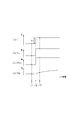
- the block diagram which shows the 1st, 2nd learning process which concerns on 1st Embodiment of this invention.
- the time chart which shows transition of the direct current
- the time chart which shows transition of the voltage between terminals of the battery cell shown in FIG. 1, and electric current based on 1st Embodiment of this invention.
- the time chart which shows the effect of the 1st learning processing concerning a 1st embodiment of the present invention.
- the block diagram which shows the identification process of the charge transfer resistance parameter (beta) and the adaptation coefficients (gamma) v and (gamma) i based on 2nd Embodiment of this invention.
- formula and approximate expression of 0A vicinity based on 2nd Embodiment of this invention The time chart which shows transition of the voltage between terminals when the electric current which flows through the battery cell based on 2nd Embodiment of this invention changes suddenly.
- the flowchart which shows the procedure of the process of the selection part based on 2nd Embodiment of this invention.
- FIG. 1 shows a battery system 10 according to the first embodiment of the present invention.
- the battery system 10 includes a device that estimates parameters representing the state of a secondary battery, that is, an assembled battery (battery pack) 20.
- the battery system 10 can supply the electric power of the assembled battery 20 to an external device (for example, a vehicle including a rotating electrical machine as an in-vehicle main machine such as a motor generator).
- the battery system 10 can also be applied as a battery system in an in-vehicle system that utilizes an auxiliary battery such as an idling stop system.
- the battery system 10 includes the assembled battery 20 and a battery ECU (Electronic Control Unit) 30.
- the assembled battery 20 includes a series connection body of a plurality of battery cells 20a.
- the assembled battery 20 is connected to an electric load (not shown) including a generator such as a motor generator, and exchanges electric power with the electric load.
- an electric load including a generator such as a motor generator, and exchanges electric power with the electric load.
- secondary battery cells such as a lithium ion secondary battery cell, are used as each battery cell 20a.
- each battery cell 20a has a positive electrode, a negative electrode, an electrolyte, and a separator that separates the positive electrode and the negative electrode within the electrolyte. .
- An electric current can be supplied to the electric load connected to the assembled battery 20 by an electrochemical reaction in the electrolyte of each battery cell.
- the battery cell 20a configured as described above essentially has an internal impedance.
- This internal impedance includes, for example, direct current impedance, charge transfer impedance, and diffusion impedance.
- the DC impedance includes the resistance of each of the positive electrode and the negative electrode, and the resistance of the electrolyte in the battery cell 20a.
- the charge transfer impedance includes an RC parallel circuit composed of a pair of charge transfer resistors and electric double layer capacitors connected in parallel to each other.
- the charge transfer resistance and electric double layer capacity are, for example, reactions at the interface between ions in the electrolyte (lithium ions) and charges in the positive electrode, and between ions in the electrolyte and charges in the negative electrode. This is based on the reaction at the interface.
- the diffusion impedance includes an RC parallel circuit composed of a diffusion resistor and a diffusion capacitor connected in parallel with each other.
- the diffusion resistance and diffusion capacity are based on, for example, ion diffusion in the electrolyte and ion diffusion in the active material in each positive and negative electrode.
- the diffusion capacity represents that the diffusion resistance changes with time.
- the battery system 10 includes a plurality of voltage sensors 21, temperature sensors 22, and current sensors 23. These sensors are examples of sensors that can measure various physical characteristics of the battery pack 20.
- the voltage sensor 21 is a voltage detection unit that detects the inter-terminal voltage CCV of the corresponding battery cell 20a and outputs a detection signal representing the inter-terminal voltage CCV of the corresponding battery cell 20a to the battery ECU 30.
- the temperature sensor 22 detects the temperature Ts of the assembled battery 20, that is, the temperature Ts of each battery cell 20a, and sends a detection signal indicating the temperature Ts of the corresponding battery cell 20a (hereinafter referred to as cell temperature Ts) to the battery ECU 30. It is the temperature detection part which outputs.
- the current sensor 23 is a current detection unit that detects a current Is flowing through the assembled battery 20 (each battery cell 20a), that is, a charging current or a discharging current, and outputs a detection signal representing the detected current Is to the battery ECU 30.
- the polarity of the detection current Is becomes negative when the detection current Is is output from the assembled battery 20 and each battery cell 20a is discharged, and the detection current Is is input to the assembled battery 20 and the battery cell 20a. Becomes positive when is charged.
- the battery ECU 30 is configured as a well-known computer including a CPU 30a, a storage device, that is, a memory 31, an I / O (not shown), and other peripheral devices.
- the memory 31 stores information VTI related to various characteristic parameters of the assembled battery 20.
- CPU30a contains the some cell calculating part 32 corresponding to each of the some battery cell 20a. Detection signals from the voltage sensor 21, the temperature sensor 22, and the current sensor 23 are input to the battery ECU 30.
- each calculation unit 32 calculates the charging rate of the corresponding battery cell 20a, and the first and second learning processes that are characteristic configurations according to the first embodiment. And do.
- the charging rate calculation process, the first learning process, and the second learning process will be described in this order.
- Each calculation unit 32 includes an OCV conversion unit 33, a voltage deviation calculation unit 34, a current estimation unit 35, and an SOC calculation unit 36 as a state estimation unit 60 for performing the charging rate calculation process.
- the OCV conversion unit 33 calculates the open-circuit voltage OCV of the battery cell 20a based on the charging rate (State Of Charge, SOC) of the battery cell 20a in the previous calculation cycle calculated by the SOC calculation unit 36 described later.
- the OCV conversion unit 33 calculates the open end voltage OCV of each battery cell 20a using an OCV map in which the SOC and the open end voltage OCV are associated in advance.
- the OCV map is stored in the memory 31 as a part of the information VTI, for example.
- the voltage deviation calculation unit 34 outputs a value obtained by subtracting the open-end voltage OCV calculated by the OCV conversion unit 33 from the inter-terminal voltage CCV of the battery cell 20a detected by the voltage sensor 21.
- the current estimation unit 35 estimates the current flowing through the battery cell 20 a based on the output value of the voltage deviation calculation unit 34 and the temperature of the battery cell 20 a detected by the temperature sensor 22 (hereinafter, battery temperature Ts). Hereinafter, the current estimation method in the current estimation unit 35 will be described.
- the equivalent circuit model (battery model) 38 of the battery cell 20a that is, the internal impedance of the battery cell 20a, and the like used by the current estimation unit 35 to estimate the current flowing through the battery cell 20a is expressed using FIG.
- the battery model 38 that equivalently simulates the electrochemical behavior of the battery cell 20a will be described.
- the battery model 38 is basically expressed as a series connection body of a power source 38a, a DC resistance model 38b, a charge transfer impedance model 38c, and a diffusion impedance model 38d.
- the DC resistance model 38b has the above-described DC resistance Rs (resistance value Rs) in the battery cell 20a, and represents a potential difference (hereinafter referred to as DC resistance voltage) in the DC resistance Rs as Vs.
- the charge transfer impedance model 38c represents a charge transfer resistance (Rr indicating the above-described charge transfer impedance in the battery cell 20a, and a potential difference (hereinafter referred to as a charge transfer resistance voltage) in the charge transfer resistance Rr is expressed as Vbv. 3, the charge transfer impedance model shown in Fig. 3 is represented only by the charge transfer resistance Rr, which is a direct current resistance, and the electric double layer capacitance is ignored, which is the calculation unit 32 in the present embodiment. This is because one calculation cycle of the charging rate calculation process of the battery cell 20a in (CPU 30a) is set sufficiently longer than the time constant of the RC parallel circuit in the charge transfer impedance.
- the diffusion impedance model 38d has the above-described diffusion impedance in the battery cell 20a. That is, the diffusion impedance model 38d includes an RC parallel circuit composed of a diffusion resistance (resistance value Rw) and a diffusion capacitance (capacitance value Cw). The potential difference in the RC parallel circuit 38d is expressed as a polarization voltage Vw.
- the DC resistance model 38b will be described.
- the DC resistance voltage Vs of the DC resistance model 38b is expressed by the following equation (eq1).
- I represents the current flowing through the battery cell 20a.
- the direct current resistance Rs depends on the temperature of the battery cell 20a.
- an Rs map in which the DC resistance Rs and the battery temperature Ts are related in advance is stored in the memory 31 as a part of the information VTI, for example.
- the Rs map is adapted so that the higher the battery temperature Ts, the lower the DC resistance Rs.
- the current estimation unit 35 has a function of calculating the DC resistance Rs based on the battery temperature Ts and the Rs map.
- the Butler-Volmer formula for each battery cell 20a in electrochemistry is represented by the following formula (eq2).
- the above equation (eq9) “ ⁇ ” represents a charge transfer resistance parameter that is a parameter related to the charge transfer resistance Rr, “ ⁇ ” represents a physical constant, and “ ⁇ ” represents the fitness coefficient.
- the above equation (eq9) indicates that the charge / discharge current I flowing through the battery cell 20a and the charge transfer resistance voltage Vbv can be related by the charge transfer resistance parameter ⁇ .
- the detection current Is is the current I flowing through the battery cell 20a.
- the equation (eq9) is an inverse hyperbola in which the charge transfer resistance parameter ⁇ derived from the Butler-Volmer equation has the current I flowing through the battery cell 20a as an independent variable and the charge transfer resistance voltage Vbv as a dependent variable. In the sine function, this represents a coefficient that determines the relationship between the inverse hyperbolic sine function and the charge transfer resistance voltage Vbv.
- the exchange current density io follows the following equation (eq10) with respect to the absolute temperature T of the battery cell 20a.
- equation (eq10) “K t , ia” represents a constant.
- the temperature characteristic of the charge transfer resistance parameter ⁇ can be expressed by the following equation (eq11).
- Equation (eq12a) has the same form as the linear equation represented by the following equation (eq12b).
- A is K t and B is ln ( ⁇ 0).
- the memory 31 uses the linear function LF with respect to the absolute temperature T of the battery cell 20a at the natural logarithm ln ( ⁇ 0) of the charge transfer resistance parameter ⁇ , that is, the set of the y intercept ln ( ⁇ 0) and the slope K t as the information. It is stored as ⁇ map information which is a part of information of VTI. That is, the current estimation unit 35 refers to the ⁇ map based on the value of the absolute temperature T based on the battery temperature Ts detected by the temperature sensor 22, and the natural logarithm of the charge transfer resistance parameter ⁇ corresponding to the reciprocal of the absolute temperature T. The value of ln ( ⁇ 0) is extracted from the ⁇ map. Then, the current estimating unit 35 calculates the value of the charge transfer resistance parameter ⁇ by exponentially expanding the extracted natural logarithm ln ( ⁇ 0) of the charge transfer resistance parameter ⁇ .
- FIG. 5 shows the relationship between the current I and the charge transfer resistance voltage Vbv based on the above equation (eq5), at different temperatures of the battery cell 20a (25 ° C., 10 ° C., 0 ° C., ⁇ 10 ° C., and ⁇ 20 ° C. ) As parameters, respectively.
- the charge transfer resistance voltage Vbv calculated by the above equation (eq5) is when the battery temperature Ts of the battery cell 20a is within a low temperature range, for example, a temperature range of 0 ° C. or less. It changes non-linearly with changes in the current I.
- the charge transfer resistance voltage Vbv using the above equation (eq5), in other words, the charge transfer resistance parameter ⁇ , the actual current I and the charge transfer resistance of the battery cell 20a in a low temperature region of, for example, 0 ° C. or less.
- the charge transfer resistance voltage Vbv having a non-linear current-voltage characteristic that matches the non-linear characteristic between the voltage Vbv and the voltage Vbv can be calculated.
- the diffusion impedance model 38d will be described.
- the polarization voltage Vw of the diffusion impedance model 38d is expressed by the following equation (eq13).
- A is represented by the following equation (eq13A)
- B is represented by the following equation (eq13B).
- the above equation (eq13) is an equation obtained by discretizing the transfer function of the RC parallel circuit 38d by bilinear transformation, and “ ⁇ T” indicates one calculation cycle of the calculation unit 32. Further, (t) given to the polarization voltage Vw and the parameter B ⁇ Is in the above equation (eq13) indicates that the polarization voltage Vw and the parameter B ⁇ Is are values in the current calculation cycle in the calculation unit 32. Show. Further, (t ⁇ 1) added to the parameter ( ⁇ A ⁇ Vw) and the parameter B ⁇ Is in the above equation (eq13) is the value in the previous calculation cycle in the calculation unit 32. It is shown that.
- information regarding each of the resistance value Rw of the resistance component term and the capacitance Cw of the capacitance component term of the RC parallel circuit 38d is the battery temperature Ts detected by the temperature sensor 22. And is stored in the memory 31 as part of the information VTI. Information relating to each of the resistance value Rw of the resistance component term and the capacitance Cw of the capacitance component term is related to the absolute temperature T based on the battery temperature Ts detected by the temperature sensor 22 as diffusion impedance information. This is because each of the resistance value Rw and the capacitance Cw depends on the battery temperature T.
- the current estimation unit 35 determines the resistance value Rw and the capacitance component term of the resistance component term in the diffusion impedance. Has a function of calculating the electrostatic capacitance Cw.
- the output value of the voltage deviation calculation unit 34 is an added value of the DC resistance voltage Vs, the charge transfer resistance voltage Vbv, and the polarization voltage Vw described above.
- the process performed by the current estimation unit 35 is a process of calculating the current that generates the added value “Vs + Vbv + Vw” as the estimated current Ie.
- the current estimation unit 35 first determines the DC resistance Rs, the charge transfer resistance parameter ⁇ , the resistance value Rw of the resistance component term of the RC parallel circuit 38d, and the capacitance Cw of the capacitance component term based on the battery temperature T. Calculate each. Then, the current estimation unit 35 sets, as the estimated current Ie, a current such that the added value on the right side of each of the equations (eq1), (eq9), and (eq13) matches the output value of the voltage deviation calculation unit 34. calculate. In this calculation process, the estimated current Ie calculated in the previous calculation cycle may be used as Is (t ⁇ 1) on the right side of the above equation (eq13).
- the SOC calculation unit 36 calculates the SOC of the battery cell 20a based on the estimated current Ie calculated by the current estimation unit 35.
- the SOC calculation unit 36 may calculate the SOC by, for example, the following equation (eq14).
- the SOC calculation unit 36 may calculate the initial SOC0 as follows, for example. Specifically, the SOC calculation unit 36 detects the voltage between the terminals of the battery cell 20a as the open-circuit voltage OCV by the voltage sensor 21 on the condition that charging / discharging of the assembled battery 20 is stopped. Then, the SOC calculation unit 36 receives the detected open-end voltage OCV as an input, and calculates the initial SOC0 using the OCV map.
- First learning process The 1st learning process about the battery cell 20a which corresponds in each calculating part 32 is demonstrated using FIG.
- This first learning process addresses the possibility that the charge transfer resistance parameter ⁇ may deviate from an appropriate value (for example, a value assumed at the time of design) due to deterioration of the battery cell 20a or the like. That is, the first learning process is a process for learning the charge transfer resistance parameter ⁇ used in the current estimation unit 35. Thereby, even if deterioration or the like occurs in the battery cell 20a, it is possible to avoid a decrease in SOC estimation accuracy due to the processing shown in FIG.
- Each calculation unit 32 includes a Vs calculation unit 40, a Vbv calculation unit 41, and a first learning unit 42 as processing units for performing the first learning process.
- the Vs calculating unit 40 is based on the DC resistance Rs calculated from the battery temperature Ts and the current detected by the current sensor 23 (hereinafter, detected current Is), and the DC resistance voltage represented by the above equation (eq1). Vs is calculated.
- the Vbv calculation unit 41 is based on the charge transfer resistance parameter ⁇ calculated from the battery temperature Ts, the detection current Is, and the correction coefficient ⁇ k calculated in the previous calculation cycle, and the charge transfer represented by the above equation (eq9).
- the resistance voltage Vbv is calculated.
- the correction coefficient ⁇ k is a parameter learned by the first learning unit 42 in order to correct the charge transfer resistance parameter ⁇ deviated from an appropriate value due to deterioration of the corresponding battery cell 20a or the like. eq15).
- ln ( ⁇ k) represents the amount of change in the Y intercept of the Arrhenius plot in FIG.
- the first learning unit 42 corrects the correction coefficient ⁇ k based on the DC resistance voltage Vs calculated by the Vs calculation unit 40, the charge transfer resistance voltage Vbv calculated by the Vbv calculation unit 41, the detection current Is, and the inter-terminal voltage CCV. To learn.
- the first learning unit 42 includes a “first deviation calculation unit 42a”, a “second deviation calculation unit 42b”, and a “first parameter estimation unit 42c”.
- a learning method (learning process) by the first learning unit 42 will be described.
- the 1st learning part 42 may be implement
- the left side of the above equation (eq17) shows the detection current deviation ⁇ Is (t) (“first”) which is the difference between the detection current Is (t) in the current calculation cycle and the detection current Is (t ⁇ 1) in the previous calculation cycle. 1 deviation ”).
- the right side of the above equation (eq17) indicates the estimated current deviation ⁇ F (t) (corresponding to “second deviation”).
- the charge transfer resistance voltage Vbv (t) of the current calculation cycle (t) shown on the right side of the above equation (eq17) is represented by the following equation (eq18).
- CCV (t) is the inter-terminal voltage CCV in the current calculation cycle (t)
- Vs (t) is the DC resistance voltage Vs in the current calculation cycle (t)
- Vw (t) is the current calculation cycle.
- the polarization voltage Vw and OCV (t) at (t) indicate the open-circuit voltage OCV at the current calculation cycle (t), respectively.
- the influence of the polarization voltage Vw and the open-circuit voltage OCV can be reduced to significantly measure the influence of the charge transfer resistance voltage Vbv when the absolute value of the detected current deviation ⁇ Is is large during vehicle acceleration or the like. This is because each of the DC resistance voltage Vs and the charge transfer resistance voltage Vbv changes to a value corresponding to the detected current deviation ⁇ Is, while the amount of change for one calculation period of the polarization voltage Vw has a time constant. This is because it is very small and can be ignored.
- FIG. 8 when the battery cell 20a is not deteriorated and the initial value of the charge transfer resistance parameter ⁇ is an appropriate value, the detection current Is and the terminal at a low temperature (for example, ⁇ 15 ° C.) The measurement result of inter-voltage CCV is shown.
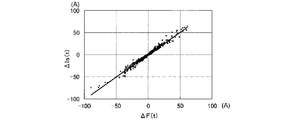
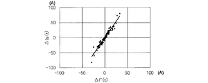
- FIG. 9 is a diagram in which the estimated current deviation ⁇ F and the detected current deviation ⁇ Is calculated based on this measurement result are plotted.
- the estimated current deviation ⁇ F is a value obtained by calculating the right side of the above equation (eq17) using the charge transfer resistance voltage Vbv calculated based on the above equation (eq18).
- the first learning unit 42 learns a correction coefficient ⁇ k for making the estimated current deviation ⁇ F coincide with the detected current deviation ⁇ Is.
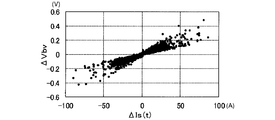
- the detected current deviation ⁇ Is is plotted on the horizontal axis without using the above equation (eq17), and the charge transfer resistance voltage Vbv in one calculation cycle using the above equation (eq18).
- FIG. 11 shows the change ⁇ Vbv plotted on the vertical axis.
- the non-linearity of the current-voltage characteristics of the battery cell 20a becomes strong at low temperatures.
- the linearity of the variation ⁇ Vbv of the charge transfer resistance voltage Vbv with respect to the detected current deviation ⁇ Is is not ensured.
- each parameter is expressed as the following equation (eq19).
- the 1st learning part 42 can calculate 1st parameter estimated value (theta) 1 (t) for every calculation period based on the following Formula (eq20) derived
- the first learning unit 42 calculates the first parameter estimated value ⁇ 1 (t) as the reciprocal “1 / ⁇ k (t)” of the correction coefficient ⁇ k (t). Then, the calculation unit 32 including the Vbv calculation unit 41 calculates the correction coefficient ⁇ k, that is, the correction coefficient calculated based on the correction coefficient ⁇ k, that is, the first parameter estimated value ⁇ 1 (t), on the charge transfer resistance parameter ⁇ of the ⁇ map corresponding to the battery temperature Ts. The charge transfer resistance parameter ⁇ is updated by multiplying ⁇ k (t). Thereby, the updated charge transfer resistance parameter ⁇ is used in the Vbv calculation unit 41 and the current estimation unit 35.
- the calculation unit 32 includes a “first update unit (update unit) 32 a” that performs the update process of the charge transfer resistance parameter ⁇ .
- the calculation unit 32 functions as a “first update unit (update unit) 32a” that performs the update process of the charge transfer resistance parameter ⁇ .
- FIG. 12 shows transitions of the true value and the estimated value of the inter-terminal voltage CCV of the battery cell 20a at a low temperature (for example, ⁇ 15 ° C.).
- the estimated value is the open-circuit voltage OCV calculated by the OCV conversion unit 33, the DC resistance voltage Vs calculated by the Vs calculation unit 40, the charge transfer resistance voltage Vbv calculated by the Vbv calculation unit 41, and This corresponds to the added value of the polarization voltage Vw calculated based on the above equation (eq13).
- the initial value of the charge transfer resistance parameter ⁇ is deviated from an appropriate value representing the charge transfer impedance model. For this reason, the estimated value of the inter-terminal voltage CCV greatly deviates from the true value during a certain period after the first learning process is started. However, thereafter, the charge transfer resistance parameter ⁇ is sequentially updated by the first learning process, so that the estimated value of the inter-terminal voltage CCV matches the true value.
- Second learning process The 2nd learning process about the battery cell 20a corresponding in each calculating part 32 is demonstrated using FIG.
- This second learning process is a process for learning the resistance value Rw of the resistance component term and the capacitance Cw of the capacitance component term in the diffusion impedance model 38d.
- Each computing unit 32 includes a second learning unit 43 in addition to the Vs calculation unit 40 and the Vbv calculation unit 41 as a processing unit for performing the second learning process, as shown in FIG.
- the second learning unit 43 learns the resistance value Rw of the resistance component term and the capacitance Cw of the capacitance component term based on the DC resistance voltage Vs, the charge transfer resistance voltage Vbv, the detection current Is, and the inter-terminal voltage CCV.
- the second learning unit 43 includes a “second parameter estimation unit 43a”.
- a learning method (learning process) by the second learning unit 43 will be described.
- FIG. 13 shows a circuit model LM used in the second learning unit 43 to learn the resistance value Rw of the resistance component term and the capacitance Cw of the capacitance component term according to this embodiment.
- This circuit model LM includes an error resistor directly connected to a parallel connection body of a resistance component term Rw and a capacitance component term Cw.
- the resistance value of the error resistor is indicated by “R E ”.
- the error resistor is provided in view of the fact that each of the charge transfer resistance voltage Vbv and the DC resistance voltage Vs can include an error.
- a change amount (hereinafter, voltage change amount ⁇ Vin) in one calculation cycle of the applied voltage Vin is expressed by the following equation (eq22).
- each parameter is expressed as the following equation (eq24).
- the second learning unit 43 can calculate the second parameter estimated value ⁇ 2 (t) based on the following equation (eq25) derived from the sequential least square method.
- the second learning unit 43 calculates the resistance value Rw of the resistance component term, the capacitance Cw of the capacitance component term, and the resistance of the error resistance based on the calculated second parameter estimated value ⁇ 2 (t) and the following equation (eq26).
- the value R E is calculated.
- the calculation unit 32 calculates diffusion impedance information regarding the resistance value Rw of the resistance component term and the capacitance Cw of the capacitance component term stored in the memory 31 in a state associated with the battery temperature Ts (absolute temperature T). Updating is performed based on the resistance value Rw and the capacitance Cw calculated, that is, learned by the second learning unit 43. The updated information is used in the current estimation unit 35. That is, in the present embodiment, the calculation unit 32 includes a “second update unit 32b” that performs the update process of the diffusion impedance information.
- the calculation unit 32 functions as a “second update unit 32b” that performs the update process of the diffusion impedance information.
- the second learning unit 43 appropriately applies a low-pass filter (LPF) that matches the time constant of the RC parallel circuit to be learned to all of the parameters Vs, Vbv, Is, and CCV input to the second learning unit 43. May be applied. Thereby, the learned resistance value Rw and capacitance Cw can be set to stable values.
- LPF low-pass filter
- SOC calculation unit 36 for example of the arithmetic unit 32, the terminal voltage CCV of the battery cell 20a detected by the voltage sensor 21, the resistance value R multiplied values of E and the detection current Is of the error resistance, DC resistance voltage Vs,
- the open end voltage OCV may be calculated by subtracting the added value of the charge transfer resistance voltage Vbv and the polarization voltage Vw. Then, the SOC calculation unit 36 may calculate the SOC of the battery cell 20a based on the calculated open-end voltage OCV and the OCV map.
- the battery ECU 30 uses a charge transfer impedance model that includes a charge transfer resistance parameter ⁇ that correlates with the battery temperature Ts (or absolute temperature T), which is a parameter corresponding to a Butler-Volmer exchange current density. For this reason, the current-voltage nonlinear characteristic of each battery cell 20a can be accurately represented even at low temperatures. Then, the battery ECU 30 sequentially updates the charge transfer resistance parameter ⁇ by the first learning process using the sequential least square method. For this reason, even if each battery cell 20a deteriorates or the initial value of the charge transfer resistance parameter ⁇ deviates from an appropriate value, it is possible to avoid a decrease in the estimation accuracy of the SOC of the battery cell 20a. it can.
- the battery ECU 30 performs the first learning process when the absolute value of the detected current deviation ⁇ Is is equal to or greater than the predetermined value Ith. For this reason, it is possible to determine when the charge transfer resistance whose nonlinear behavior is dominant in the behavior of the voltage fluctuation of the battery cell 20a, and at this determination, it is possible to calculate the correction coefficient ⁇ k for correcting the charge transfer resistance parameter ⁇ . . As a result, erroneous learning of the correction coefficient K due to the influence of the polarization voltage Vw can be avoided.
- the battery ECU 30 obtains the resistance value Rw of the resistance component term and the capacitance Cw of the capacitance component term in the RC parallel equivalent circuit model 38d by the second learning process using the error resistance connected in series to the RC parallel equivalent circuit model 38d. Updated sequentially. For this reason, it is possible to suppress the influence of errors included in the DC resistance voltage Vs and the charge transfer resistance voltage Vbv on the calculation of the polarization voltage Vw. On the other hand, when no error resistor is provided, the estimated resistance value Rw of the resistance component term includes the influence of the error, and there is a concern that the estimation accuracy of the resistance value Rw may be reduced.
- each calculation unit 32 sequentially identifies the fitness coefficient ⁇ in addition to the charge transfer resistance parameter ⁇ by an adaptive digital filter. Update. This is in view of the possibility that the adaptation coefficient ⁇ may deviate from an appropriate value (for example, a value adapted at the time of design) due to deterioration or the like of the battery cell 20a.
- FIG. 14 shows a processing unit 61 provided in each calculation unit 32 for identifying the charge transfer resistance parameter ⁇ and the fitness coefficient ⁇ .
- the processing unit 61 has a configuration corresponding to the first learning unit 42 described in the first embodiment. That is, the charge transfer resistance parameter ⁇ and the fitness coefficient ⁇ identified by the processing unit 61 are used for calculation of the estimated current Ie in the current estimation unit 35 constituting the state estimation unit 60. Specifically, the current estimation unit 35 updates the parameters ⁇ and ⁇ included in the right side of the above equation (eq9) used for calculating the estimated current Ie with the input parameters ⁇ and ⁇ .
- the processing unit 61 includes a parameter identification unit 50.
- the parameter identification unit 50 includes a first identification unit 51 that identifies the charge transfer resistance parameter ⁇ and a second identification unit 52 that identifies the fitness coefficient ⁇ .
- initial parameter ⁇ map The initial value of the charge transfer resistance parameter (hereinafter referred to as “initial parameter ⁇ map”) is expressed by the following equation (eq27).
- the initial parameter ⁇ map is formulated into a form in which the natural logarithm of the initial parameter ⁇ map is a linear expression with respect to the reciprocal of the battery temperature Ts. It is stored in the memory 31 as part of the VTI. For this reason, if the battery temperature Ts can be grasped, the initial parameter ⁇ map can be determined. Thereby, when the battery ECU 30 is activated, the initial value of the charge transfer resistance parameter ⁇ , that is, the initial parameter ⁇ map can be set accurately.
- the charge transfer resistance parameter ⁇ is defined as in the following equation (eq29).
- each calculation unit 32 receives the battery temperature Ts as an input and calculates a natural logarithm value corresponding to the battery temperature Ts based on the mathematical formula stored in the memory 31 in the form of the above equation (eq28). .
- This calculation function is provided, for example, in the current estimation unit 35 shown in FIG. That is, the current estimation unit 35 functions as a calculation unit.
- the current estimation unit 35 obtains an initial parameter ⁇ map by converting the calculated natural logarithm value ln ( ⁇ map) into an exponential function, and multiplies the initial parameter ⁇ map by a correction coefficient ⁇ k as shown in the above equation (eq29).
- a charge transfer resistance parameter ⁇ is calculated.
- the charge transfer resistance parameter ⁇ is a parameter that changes exponentially with respect to the temperature of the battery cell 20a as shown in the above equation (eq28). As shown in FIG. 4, the digit can be changed so as to change greatly. For this reason, when using an adaptive digital filter, it is desirable not to directly identify the charge transfer resistance parameter ⁇ but to identify the correction coefficient ⁇ k, which is a value obtained by standardizing the charge transfer resistance parameter ⁇ . This is to avoid a reduction in the identification accuracy of the charge transfer resistance parameter ⁇ caused by the minimum operation unit (Least Significant Bit: LSB) in each operation unit 32.
- LSB Minimum Opera unit
- the charge transfer resistance parameter ⁇ is directly identified. Since the charge transfer resistance parameter ⁇ varies greatly depending on the operating temperature of the battery cell 20a, the charge transfer resistance parameter ⁇ varies depending on the temperature during the travel of the vehicle or the time when the charge transfer resistance parameter ⁇ converges depending on the season. There is a concern that the identification accuracy of ⁇ is lowered. On the other hand, since the correction coefficient ⁇ k is normalized, it is possible to calculate a stable correction coefficient ⁇ k. Further, by normalizing the correction coefficient ⁇ k, it is possible to avoid concerns such as a loss of digits, so that it is possible to avoid a decrease in the identification accuracy of the charge transfer resistance parameter ⁇ .
- the initial parameter ⁇ map is stored in the memory 31 in the form expressed by the above equation (eq28). For this reason, the change width of ln ( ⁇ map) in the operating temperature range of the battery cell 20a can be reduced. Thereby, the accuracy of the initial parameter ⁇ map can be increased.
- the initial parameter ⁇ map stored in the memory 31 may deviate from the design-use conformity indicated by the solid line, as indicated by the one-dot chain line in FIG.
- This deviation can be corrected by the correction coefficient ⁇ k.
- the Y-intercept of the Arrhenius plot changes due to deterioration or the like.
- this change is corrected by the correction coefficient ⁇ k.
- K t denotes a constant determined from the physical constants. For this reason, the inclinations of the solid line and the alternate long and short dash line in FIG. 15 do not change before and after the deterioration of the battery cell 20a or the like.
- the above equation (eq32) is an equation that can be approximated around 0 A of the current I flowing through the battery cell 20a, and is a linear equation of the charge transfer resistance voltage Vbv with respect to the current I.
- “ ⁇ ⁇ T ⁇ ⁇ map ⁇ ⁇ k” has a dimension of resistance
- ⁇ is a physical constant
- the difference between the inter-terminal voltage CCV (t) detected by the voltage sensor 21 in the current calculation cycle and the inter-terminal voltage CCV (t ⁇ 1) in the previous calculation cycle is defined as a detected voltage deviation ⁇ V (t).
- the detected voltage deviation ⁇ V (t) is expressed by the following equation (eq33) with reference to the above equation (eq18).
- Each calculation unit 32 sequentially identifies the correction coefficient ⁇ k using the detected voltage deviation ⁇ V (t) and the detected current deviation ⁇ I (t) when the detected current Is greatly changes.
- FIG. 17 (a) the transition of the voltage between the terminals of the battery cell 20a is shown in FIG. 17 (a), and the transition of the current I flowing in the battery cell 20a is shown in the reference (b) of FIG.
- a constant load is applied to the battery cell 20a after the time t1 in the no-load state.
- the voltage drop amount ⁇ Vw having a large time constant is sufficiently smaller than the voltage drop amount “ ⁇ Vs + ⁇ Vbv” having no time constant.
- the change amount ⁇ OCV of the open-circuit voltage OCV is also sufficiently smaller than the voltage drop amount “ ⁇ Vs + ⁇ Vbv”. For this reason, each change amount ⁇ OCV (t), ⁇ Vw (t) in one sufficiently short calculation period can be ignored. Therefore, the above equation (eq30) can be expressed as the following equation (eq34).
- each calculation unit 32 can extract the DC resistance voltage Vs and the charge transfer resistance voltage Vbv from the detected voltage deviation ⁇ V. Further, by ignoring each change amount ⁇ OCV (t), ⁇ Vw (t), the calculation load in each calculation unit 32 can be reduced.
- each parameter is represented as the following equation (eq36).
- ya represents an observed value.
- the model estimated value yaest and the estimation error ⁇ a are expressed by the following equation (eq37).
- Each calculation unit 32 sequentially identifies the parameter estimation value ⁇ a by the sequential least square method based on the following equation (eq38) so as to minimize the estimation error ⁇ a.
- the parameter identification unit 50 receives the observed value ya (t) determined by the detected voltage deviation ⁇ V (t), the detected current deviation ⁇ I (t), and the DC resistance Rs as input, and sequentially minimizes it based on the above equations (eq37) and (eq38).
- the parameter estimation value ⁇ a is sequentially identified by the square method, and the correction coefficient ⁇ k is calculated from the identified parameter estimation value ⁇ a.
- the first identifying unit 51 uses the observation value ya (t) based on the DC resistance Rs calculated from the detected voltage deviation ⁇ V (t), the detected current deviation ⁇ I (t), and the battery temperature Ts. Is calculated.
- the first identification unit 51 receives the observed value ya as input, sequentially identifies the parameter estimated value ⁇ a by the sequential least square method based on the above equations (eq37) and (eq38), and corrects the correction coefficient ⁇ k from the identified parameter estimated value ⁇ a. Is calculated.
- the processing unit 61 includes a current change amount calculation unit 53, a voltage change amount calculation unit 54, and a selection unit 55 in addition to the parameter identification unit 50.
- the detected current deviation ⁇ I (t) is calculated by the current change amount calculation unit 53, and the detected voltage deviation ⁇ V (t) is calculated by the voltage change amount calculation unit 54.
- the DC resistance Rs is calculated based on the Rs map described above.
- the adaptation coefficient ⁇ is a proportionality coefficient that defines the relationship between the charge transfer resistance voltage Vbv and the current I flowing through the battery cell 20a.
- the fitness coefficient ⁇ c when the battery cell 20a is charged may be set separately from the fitness coefficient ⁇ d when the battery cell 20a is discharged.
- the charge-side fitness coefficient ⁇ c is set to 0.25, for example, and the discharge-side fitness coefficient ⁇ d is set to 0.14, for example.
- the processing unit 61 calculates the difference between the detected voltage deviation ⁇ V (t) and the detected current deviation ⁇ I (t) when the current I changes greatly from time t ⁇ 1 to time t.
- the fitness coefficient ⁇ is sequentially identified from the relationship.
- ⁇ v represents a first coefficient that is a fitting coefficient that defines expansion or contraction in the direction of the charge transfer resistance voltage Vbv in the Butler-Volmer equation
- ⁇ i represents the battery cell 20a in the Butler-Volmer equation.
- regulates the expansion or contraction in the direction of the flowing electric current I is shown.
- the processing unit 61 identifies the first coefficient ⁇ v at time t, and applies the first coefficient ⁇ v identified after one calculation cycle to the second coefficient ⁇ i.
- each parameter is expressed as the following equation (eq40).
- yb represents an observed value.
- the model estimated value ybest and the estimation error ⁇ b are expressed by the following equation (eq41).
- the processing unit 61 sequentially identifies the parameter estimated value ⁇ b by the sequential least square method based on the following equation (eq42) so as to minimize the estimation error ⁇ b. Then, the processing unit 61 calculates the first coefficient ⁇ v by taking the reciprocal of the parameter estimated value ⁇ b.
- the second identification unit 52 of the processing unit 61 calculates the observed value yb (t) based on the detected voltage deviation ⁇ V (t), the detected current deviation ⁇ I (t), and the DC resistance Rs.
- the second identification unit 52 receives the observed value yb as input, and sequentially identifies the parameter estimated value ⁇ b by the successive least square method based on the above equations (eq41) and (eq42).
- the second identification unit 52 calculates the first coefficient ⁇ v by taking the reciprocal of the parameter estimated value ⁇ b.
- the second identification unit 52 applies the identified first coefficient ⁇ v to the second coefficient ⁇ i.
- the identification of the correction coefficient ⁇ k in the first identification unit 51 is performed when the current I flowing through the battery cell 20a is small (for example, smaller than a predetermined value).
- the identification of the first and second coefficients ⁇ v and ⁇ i in the second identification unit 52 is performed when the current I flowing through the battery cell 20a is large (for example, larger than the predetermined value). Therefore, in the present embodiment, the calculation unit 32 includes a selection unit 55 that selects which of the charge transfer resistance parameter ⁇ and the adaptation coefficient ⁇ is identified in the current calculation cycle.
- the selection process executed by the processing unit 61 including the selection unit 55 will be described with reference to FIG. This process is repeatedly executed by the processing unit 61 at a predetermined calculation cycle, for example.
- step S10 the selection unit 55 determines whether or not the absolute value of the detected current deviation ⁇ I (t) is equal to or greater than a specified value Id.
- This process is a process for determining whether or not each of the changes ⁇ OCV and ⁇ Vw is in a state that can be ignored, as indicated by the above equation (eq34).
- step S10 the selection process proceeds to step S11.
- step S11 the selection unit 55 sets the first condition that the absolute value of the detection current Is (t) in the current calculation cycle is less than the threshold Ir, and the detection current Is (t-1) in the previous calculation cycle. It is determined whether the logical product of the second condition that the absolute value of is less than the threshold value Ir is true, that is, whether both the first condition and the second condition are satisfied.
- the threshold Ir is 1 ⁇ 2 of the current range SI that can approximate the Butler-Volmer equation represented by the above equation (eq9) with the approximate equation of the above equation (eq31). This value is set larger as the battery temperature Ts is higher.
- the higher the battery temperature Ts the larger the threshold Ir is set because the slope when the current I flowing through the battery cell 20a is in the vicinity of 0 A in the Butler-Volmer equation shown in FIG. 5 is the battery cell 20a. This is because the temperature becomes smaller and the shape becomes more linear.
- step S11 the selection process proceeds to step S12.
- step S12 the first identification unit 51 identifies the correction coefficient ⁇ k.
- step S13 the selection process proceeds to step S13, and the second identification unit 52 identifies the first coefficient ⁇ v and the second coefficient ⁇ i.
- the correction coefficient ⁇ k, the first coefficient ⁇ v, and the second coefficient ⁇ i identified by the parameter identification unit 50 are input to the current estimation unit 35.
- the charge transfer resistance parameter ⁇ is updated based on the correction coefficient ⁇ k.
- the current estimation unit 35 calculates the estimated current Ie based on the updated charge transfer resistance parameter ⁇ , the first coefficient ⁇ v, and the second coefficient ⁇ i.
- the inter-terminal voltage CCV the inter-terminal voltage estimated value Ve
- the estimated value Ve is the open-circuit voltage OCV calculated by the OCV conversion unit 33, the DC resistance voltage Vs calculated by the Vs calculation unit 40, and the charge transfer calculated using the updated charge transfer resistance parameter ⁇ .
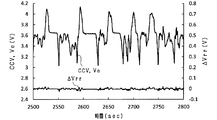
- the predetermined traveling mode in FIG. 20 is the LA # 4 mode (one of traveling patterns for exhaust gas measurement).
- the inter-terminal voltage CCV, the inter-terminal voltage estimated value Ve, and the estimated value Ve and the inter-terminal voltage CCV at a low temperature (for example, ⁇ 20 ° C.) where the error ⁇ Vrr is likely to be large.
- the transition of the error ⁇ Vrr is shown. Even at low temperatures, the error ⁇ Vrr is maintained in a very small state. For this reason, in FIG. 20, the transition of the inter-terminal voltage CCV and the transition of the estimated value Ve are almost overlapped.
- FIG. 21 shows a correlation diagram between the detected current Is, the estimated value of the inter-terminal voltage CCV (indicated by Ve), and the detected value of the inter-terminal voltage CCV (indicated by CCV) in the data period shown in FIG.
- the nonlinear characteristic between the detected current Is and the estimated value Ve of the inter-terminal voltage CCV can be expressed with high accuracy, and the inter-terminal voltage CCV of the battery cell 20a can be estimated with high accuracy. it can.
- the charge transfer impedance model can be appropriately updated. Thereby, the calculation accuracy of the estimated voltage Ve of the inter-terminal voltage CCV can be increased.
- the charge transfer resistance parameter ⁇ may be directly identified without using the correction coefficient ⁇ k based on the following equation (eq44) instead of the above equation (eq17).
- the diffusion resistance model is not limited to an RC equivalent circuit model including one parallel connection body of a resistor and a capacitor, but may be an RC equivalent circuit model in which a plurality of the parallel connection bodies are connected in series.
- the SOC is estimated as the state of the battery cell 20a, but is not limited thereto.
- the maximum power that can be discharged from the battery cell 20a over a specified time may be estimated, or the deterioration state of the battery cell 20a may be estimated.
- the second learning process is not essential.
- the initial parameter ⁇ map may be stored in the memory 31 as a part of the information VTI, for example, according to the above equation (eq27).
- the natural logarithm of the initial parameter ⁇ map is formulated into a linear expression with respect to the reciprocal of the battery temperature Ts and stored in the memory 31 as a part of the information VTI, for example, but is not limited thereto.
- the natural logarithm of the initial parameter ⁇ map may be mapped in the form of a linear expression with respect to the reciprocal of the battery temperature Ts and stored in the memory 31 as a part of the information VTI, for example.
- each calculation unit 32 selects a natural logarithm value corresponding to the battery temperature Ts from the stored natural logarithm values of the initial parameter ⁇ map.
- the battery temperature Ts is measured at least three points, and based on the measured values of at least three battery temperatures Ts.
- the map can be created. For this reason, the adaptation operation
- the threshold Ir may be set to a different value depending on whether the battery cell 20a is charged or discharged if the linearity in the vicinity of 0A is maintained. Further, in the case where the discharge current and the charge current are different depending on how the battery cell 20a is used, the first embodiment and the second embodiment are also established even in a region where the linearity near 0A is not maintained. A mode in which the two identification units 52 are combined may be employed. Furthermore, since the fitness coefficient ⁇ c when the battery cell 20a is generally charged and the fitness coefficient ⁇ d when the battery cell 20a is discharged are often different, ⁇ c and ⁇ d are different during charging and discharging, respectively. It is effective to improve the accuracy by separating and identifying.
- an opportunity to identify the first and second coefficients ⁇ v and ⁇ i may be secured even when an affirmative determination is made in step S11 in FIG.
- the resistance value Rw of the resistance component term and the capacitance Cw of the capacitance component term used in the current estimation unit 35 are learned by the second learning unit 43 described in FIG. 6 of the first embodiment. May be.
- the battery cell 20a is not limited to a lithium ion secondary battery, but may be another secondary battery such as a nickel metal hydride battery.
- the battery temperature used for each process is not limited to the detection value of the temperature sensor 22, but may be a battery temperature estimated by h using any of various known battery temperature estimation methods. Good.
- the application target of the present invention is not limited to vehicles.
Landscapes
- Engineering & Computer Science (AREA)
- Manufacturing & Machinery (AREA)
- Chemical & Material Sciences (AREA)
- Chemical Kinetics & Catalysis (AREA)
- Electrochemistry (AREA)
- General Chemical & Material Sciences (AREA)
- Physics & Mathematics (AREA)
- General Physics & Mathematics (AREA)
- Power Engineering (AREA)
- Secondary Cells (AREA)
Priority Applications (2)
| Application Number | Priority Date | Filing Date | Title |
|---|---|---|---|
| DE112016001065.6T DE112016001065B4 (de) | 2015-03-06 | 2016-03-07 | Batteriezustandsschätzvorrichtung |
| US15/556,138 US10663524B2 (en) | 2015-03-06 | 2016-03-07 | Battery state estimating apparatus |
Applications Claiming Priority (4)
| Application Number | Priority Date | Filing Date | Title |
|---|---|---|---|
| JP2015045161 | 2015-03-06 | ||
| JP2015-045161 | 2015-03-06 | ||
| JP2015231112A JP6455409B2 (ja) | 2015-03-06 | 2015-11-26 | 電池状態推定装置 |
| JP2015-231112 | 2015-11-26 |
Publications (1)
| Publication Number | Publication Date |
|---|---|
| WO2016143728A1 true WO2016143728A1 (ja) | 2016-09-15 |
Family
ID=56880208
Family Applications (1)
| Application Number | Title | Priority Date | Filing Date |
|---|---|---|---|
| PCT/JP2016/056932 WO2016143728A1 (ja) | 2015-03-06 | 2016-03-07 | 電池状態推定装置 |
Country Status (2)
| Country | Link |
|---|---|
| DE (1) | DE112016001065B4 (de) |
| WO (1) | WO2016143728A1 (de) |
Cited By (2)
| Publication number | Priority date | Publication date | Assignee | Title |
|---|---|---|---|---|
| CN107037365A (zh) * | 2016-11-16 | 2017-08-11 | 上海中兴派能能源科技股份有限公司 | 一种动力锂电池电芯的测量方法 |
| CN112114255A (zh) * | 2020-09-18 | 2020-12-22 | 中国计量大学 | 一种基于联合集合卡尔曼滤波的锂电池荷电状态估计方法 |
Citations (3)
| Publication number | Priority date | Publication date | Assignee | Title |
|---|---|---|---|---|
| JP2008058278A (ja) * | 2006-09-04 | 2008-03-13 | Toyota Motor Corp | 二次電池の内部状態推定装置、二次電池の内部状態推定方法、プログラム、および記録媒体 |
| WO2011118080A1 (ja) * | 2010-03-23 | 2011-09-29 | 古河電気工業株式会社 | 電池内部状態推定装置および電池内部状態推定方法 |
| US20160039419A1 (en) * | 2014-05-12 | 2016-02-11 | GM Global Technology Operations LLC | Battery state estimation systems and methods using a nonlinear resistance element |
Family Cites Families (2)
| Publication number | Priority date | Publication date | Assignee | Title |
|---|---|---|---|---|
| DE10126891A1 (de) | 2001-06-01 | 2002-12-05 | Vb Autobatterie Gmbh | Verfahren zur Vorhersage der Belastbarkeit eines elektrochemischen Elementes |
| JP3747826B2 (ja) | 2001-09-05 | 2006-02-22 | 日産自動車株式会社 | 二次電池の充電率推定装置 |
-
2016
- 2016-03-07 WO PCT/JP2016/056932 patent/WO2016143728A1/ja active Application Filing
- 2016-03-07 DE DE112016001065.6T patent/DE112016001065B4/de active Active
Patent Citations (3)
| Publication number | Priority date | Publication date | Assignee | Title |
|---|---|---|---|---|
| JP2008058278A (ja) * | 2006-09-04 | 2008-03-13 | Toyota Motor Corp | 二次電池の内部状態推定装置、二次電池の内部状態推定方法、プログラム、および記録媒体 |
| WO2011118080A1 (ja) * | 2010-03-23 | 2011-09-29 | 古河電気工業株式会社 | 電池内部状態推定装置および電池内部状態推定方法 |
| US20160039419A1 (en) * | 2014-05-12 | 2016-02-11 | GM Global Technology Operations LLC | Battery state estimation systems and methods using a nonlinear resistance element |
Cited By (3)
| Publication number | Priority date | Publication date | Assignee | Title |
|---|---|---|---|---|
| CN107037365A (zh) * | 2016-11-16 | 2017-08-11 | 上海中兴派能能源科技股份有限公司 | 一种动力锂电池电芯的测量方法 |
| CN112114255A (zh) * | 2020-09-18 | 2020-12-22 | 中国计量大学 | 一种基于联合集合卡尔曼滤波的锂电池荷电状态估计方法 |
| CN112114255B (zh) * | 2020-09-18 | 2023-02-28 | 中国计量大学 | 一种基于联合集合卡尔曼滤波的锂电池荷电状态估计方法 |
Also Published As
| Publication number | Publication date |
|---|---|
| DE112016001065B4 (de) | 2021-12-23 |
| DE112016001065T5 (de) | 2018-01-04 |
Similar Documents
| Publication | Publication Date | Title |
|---|---|---|
| JP6455409B2 (ja) | 電池状態推定装置 | |
| US10890625B2 (en) | Battery state estimating device | |
| JP4692246B2 (ja) | 二次電池の入出力可能電力推定装置 | |
| JP5616464B2 (ja) | 二次電池の充電状態推定装置 | |
| CN108369258B (zh) | 状态估计装置、状态估计方法 | |
| US10048319B2 (en) | Estimating of the state of charge of a battery | |
| JP6409721B2 (ja) | 電池状態推定装置 | |
| CN109669131B (zh) | 一种工况环境下动力电池soc估算方法 | |
| WO2016067587A1 (ja) | バッテリのパラメータ推定装置 | |
| WO2013168349A1 (ja) | バッテリの充電率推定装置 | |
| WO1999061929A1 (en) | Means for estimating charged state of battery and method for estimating degraded state of battery | |
| CN105283773A (zh) | 电池的健康度估计装置以及健康度估计方法 | |
| JP6428402B2 (ja) | 電池エネルギ予測装置 | |
| KR20130061719A (ko) | 전지 상태 추정 장치 및 전지 상태 추정 방법 | |
| JP5163542B2 (ja) | 二次電池の入出力可能電力推定装置 | |
| WO2017179175A1 (ja) | 推定装置、推定プログラムおよび充電制御装置 | |
| WO2019116815A1 (ja) | 二次電池監視装置、二次電池状態演算装置および二次電池状態推定方法 | |
| JP2017223536A (ja) | 電池状態推定装置および電池状態推定方法 | |
| WO2018025350A1 (ja) | 推定装置、推定プログラムおよび充電制御装置 | |
| WO2016143728A1 (ja) | 電池状態推定装置 | |
| CN112189143B (zh) | 用于估计电池的充电状态的设备 | |
| WO2018025306A1 (ja) | 推定装置、推定プログラムおよび充電制御装置 | |
| JP6428494B2 (ja) | 電池状態推定装置 | |
| JP4720364B2 (ja) | 二次電池の内部抵抗推定装置 | |
| JP7251737B2 (ja) | 推定装置 |
Legal Events
| Date | Code | Title | Description |
|---|---|---|---|
| 121 | Ep: the epo has been informed by wipo that ep was designated in this application |
Ref document number: 16761696 Country of ref document: EP Kind code of ref document: A1 |
|
| WWE | Wipo information: entry into national phase |
Ref document number: 112016001065 Country of ref document: DE Ref document number: 15556138 Country of ref document: US |
|
| 122 | Ep: pct application non-entry in european phase |
Ref document number: 16761696 Country of ref document: EP Kind code of ref document: A1 |