WO2016143259A1 - 操作装置 - Google Patents
操作装置 Download PDFInfo
- Publication number
- WO2016143259A1 WO2016143259A1 PCT/JP2016/000711 JP2016000711W WO2016143259A1 WO 2016143259 A1 WO2016143259 A1 WO 2016143259A1 JP 2016000711 W JP2016000711 W JP 2016000711W WO 2016143259 A1 WO2016143259 A1 WO 2016143259A1
- Authority
- WO
- WIPO (PCT)
- Prior art keywords
- defining
- shaft portion
- shaft
- operating device
- axis
- Prior art date
- Legal status (The legal status is an assumption and is not a legal conclusion. Google has not performed a legal analysis and makes no representation as to the accuracy of the status listed.)
- Ceased
Links
Images





Classifications
-
- H—ELECTRICITY
- H01—ELECTRIC ELEMENTS
- H01H—ELECTRIC SWITCHES; RELAYS; SELECTORS; EMERGENCY PROTECTIVE DEVICES
- H01H25/00—Switches with compound movement of handle or other operating part
- H01H25/04—Operating part movable angularly in more than one plane, e.g. joystick
- H01H25/041—Operating part movable angularly in more than one plane, e.g. joystick having a generally flat operating member depressible at different locations to operate different controls
-
- H—ELECTRICITY
- H01—ELECTRIC ELEMENTS
- H01H—ELECTRIC SWITCHES; RELAYS; SELECTORS; EMERGENCY PROTECTIVE DEVICES
- H01H21/00—Switches operated by an operating part in the form of a pivotable member acted upon directly by a solid body, e.g. by a hand
- H01H21/02—Details
- H01H21/18—Movable parts; Contacts mounted thereon
- H01H21/22—Operating parts, e.g. handle
-
- H—ELECTRICITY
- H01—ELECTRIC ELEMENTS
- H01H—ELECTRIC SWITCHES; RELAYS; SELECTORS; EMERGENCY PROTECTIVE DEVICES
- H01H13/00—Switches having rectilinearly-movable operating part or parts adapted for pushing or pulling in one direction only, e.g. push-button switch
- H01H13/70—Switches having rectilinearly-movable operating part or parts adapted for pushing or pulling in one direction only, e.g. push-button switch having a plurality of operating members associated with different sets of contacts, e.g. keyboard
-
- H—ELECTRICITY
- H01—ELECTRIC ELEMENTS
- H01H—ELECTRIC SWITCHES; RELAYS; SELECTORS; EMERGENCY PROTECTIVE DEVICES
- H01H21/00—Switches operated by an operating part in the form of a pivotable member acted upon directly by a solid body, e.g. by a hand
-
- H—ELECTRICITY
- H01—ELECTRIC ELEMENTS
- H01H—ELECTRIC SWITCHES; RELAYS; SELECTORS; EMERGENCY PROTECTIVE DEVICES
- H01H25/00—Switches with compound movement of handle or other operating part
- H01H25/008—Operating part movable both angularly and rectilinearly, the rectilinear movement being perpendicular to the axis of angular movement
-
- H—ELECTRICITY
- H01—ELECTRIC ELEMENTS
- H01H—ELECTRIC SWITCHES; RELAYS; SELECTORS; EMERGENCY PROTECTIVE DEVICES
- H01H21/00—Switches operated by an operating part in the form of a pivotable member acted upon directly by a solid body, e.g. by a hand
- H01H21/02—Details
- H01H21/04—Cases; Covers
-
- H—ELECTRICITY
- H01—ELECTRIC ELEMENTS
- H01H—ELECTRIC SWITCHES; RELAYS; SELECTORS; EMERGENCY PROTECTIVE DEVICES
- H01H2217/00—Facilitation of operation; Human engineering
- H01H2217/028—Facilitation of operation; Human engineering on planes with different or alterable inclination, e.g. convex plane
-
- H—ELECTRICITY
- H01—ELECTRIC ELEMENTS
- H01H—ELECTRIC SWITCHES; RELAYS; SELECTORS; EMERGENCY PROTECTIVE DEVICES
- H01H2217/00—Facilitation of operation; Human engineering
- H01H2217/028—Facilitation of operation; Human engineering on planes with different or alterable inclination, e.g. convex plane
- H01H2217/03—Concave plane
-
- H—ELECTRICITY
- H01—ELECTRIC ELEMENTS
- H01H—ELECTRIC SWITCHES; RELAYS; SELECTORS; EMERGENCY PROTECTIVE DEVICES
- H01H2221/00—Actuators
- H01H2221/008—Actuators other then push button
- H01H2221/016—Lever; Rocker
-
- H—ELECTRICITY
- H01—ELECTRIC ELEMENTS
- H01H—ELECTRIC SWITCHES; RELAYS; SELECTORS; EMERGENCY PROTECTIVE DEVICES
- H01H2223/00—Casings
-
- H—ELECTRICITY
- H01—ELECTRIC ELEMENTS
- H01H—ELECTRIC SWITCHES; RELAYS; SELECTORS; EMERGENCY PROTECTIVE DEVICES
- H01H2229/00—Manufacturing
- H01H2229/064—Eliminating tolerances
-
- H—ELECTRICITY
- H01—ELECTRIC ELEMENTS
- H01H—ELECTRIC SWITCHES; RELAYS; SELECTORS; EMERGENCY PROTECTIVE DEVICES
- H01H2231/00—Applications
- H01H2231/026—Car
Definitions
- the present disclosure relates to an operation device including an operation unit that rotates around a predetermined axis.
- an operation device having an operation unit that rotates around a predetermined axis, the operation unit is rotated by being pressed by an operator, and the operation unit is a switch that opens and closes an electrical contact.
- a linked one has been proposed.
- an insertion hole is provided in the upper end of the key switch body as the operation unit, and the key switch body is pressed and rotated by a finger by passing a hinge shaft through the insertion hole.
- An operation device that presses a micro switch via the touch panel has been proposed (see, for example, Patent Document 1).
- An object of the present disclosure is to provide an operation device including an operation unit that rotates about a predetermined axis, and suppresses the generation of friction associated with the rotation of the operation unit, while the backlash of the operation unit in the thrust direction is reduced. Reduce.
- the operation device is provided along the axis and protrudes in a direction opposite to the operation unit that rotates around a predetermined axis when pressed by the operator.
- the shaft portion having the first end portion and the second end portion, which operates integrally with the operation portion, and a part of the shaft portion is inserted in a specific direction, and the inserted shaft portion is moved in the radial direction.
- the guide to be regulated, the first defining portion that abuts the first end portion of the shaft portion inserted into the guide from the thrust direction and defines the position of the shaft portion in the thrust direction, and elastic deformation when the shaft portion is inserted into the guide
- a second defining portion that is brought into pressure contact with the second end portion of the shaft portion from the thrust direction by a restoring force from the elastic deformation and abuts the first end portion of the shaft portion against the first defining portion
- a part of the shaft portion provided along the axis of rotation in the operation portion is inserted into the guide in a specific direction, and the guide is in the radial direction of the inserted shaft portion.
- the movement in the direction (that is, the direction orthogonal to the axis) is restricted.
- the second defining portion is elastically deformed when inserted into the part of the guides, and is thereby brought into pressure contact with the second end portion of the shaft portion from the thrust direction by a restoring force from the elastic deformation. Then, the first end portion of the shaft portion is in good contact with the first defining portion. For this reason, the position of the shaft portion in the thrust direction is stably maintained at a position where the first end portion contacts the first defining portion. For this reason, the operation part which operates integrally with the shaft part can also reduce backlash in the thrust direction.
- the locking portion provided integrally with the second defining portion abuts on the second end portion of the shaft portion after being inserted into the guide, so that the shaft portion moves from the guide in a direction opposite to the specific direction. To suppress the withdrawal. For this reason, the configuration for reducing the backlash in the thrust direction of the operation unit as described above is stably maintained. In addition, since the play in the thrust direction is reduced by using the restoring force from the elastic deformation of the second defining portion, it is also possible to prevent the operation portion from becoming difficult to rotate due to friction. Furthermore, since the locking portion is configured integrally with the second defining portion, the device configuration can be simplified.
- FIG. 4 is a diagram schematically showing a cross section taken along line IV-IV in FIG. 3. It is a disassembled perspective view which shows an operating device.
- FIG. 6 is a cross-sectional view taken along line VI-VI in FIG. 5.
- FIG. 6 is a cross-sectional view taken along line VII-VII in FIG. 5.
- FIG. 6 is a view taken in the direction of arrow IIX in FIG. FIG.
- FIG. 6 is a view taken in the direction of arrow IIX in FIG. It is an expansion perspective view which shows the 2nd bearing part of an operating device. It is explanatory drawing which shows the effect of the latching
- FIG. 6 is a cross-sectional view taken along line XII-XII in FIG. 5.
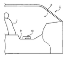
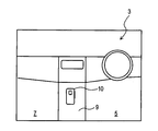
- the vehicle 1 provided with the operation device 10 includes a console 9 between a driver seat 5 and a passenger seat 7 provided inside the passenger compartment 3. .
- the operating device 10 is provided on the upper surface of the console 9.
- the controller device 10 includes an operation unit 13 that protrudes from the right side surface of the housing 11.
- the operation unit 13 can be pushed inward by the driver (not shown in the figure: an example of an operator) seated in the driver's seat 5 with the thumb F of the left hand H as indicated by the arrow P.
- front, rear, left, right, and up and down directions of the vehicle 1 when the operating device 10 is installed in this way may be referred to as front and rear, right and left, up and down in the operating device 10.
- each of these directions is only a direction defined in order to briefly explain the relative positional relationship between the respective parts constituting the controller device 10.
- the direction in which the operating device 10 is directed is arbitrary.
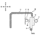
- a circuit board 17 on which a tactile switch 15 is mounted is disposed inside the housing 11.
- the plate portion 31 to which the operation portion 13 is connected is configured to be rotatable about the axis of the shaft portions 33 and 34.
- the plate portion 31 is provided with a protrusion 36 at a position facing the tactile switch 15 (strictly speaking, a position facing the push button of the tactile switch 15). For this reason, when the operation part 13 is pushed in as described above, the plate part 31 and the projecting part 36 rotate about the axis of the shaft parts 33 and 34, and the push button of the tactile switch 15 is pressed by the projecting part 36.
- the 4 to 6, only the push button of the tactile switch 15 is illustrated and denoted by reference numeral 15.
- FIG. 5 is an exploded perspective view showing the configuration of the support mechanism for the circuit board 17 and the operation unit 13. As shown in FIG. 5, the support mechanism is configured around the case 20.
- a rectangular recess 21 for receiving the circuit board 17 is formed on the right side surface of the case 20 from the upper end of the case 20.
- the recess 21 has a length in the left-right direction (ie, depth) longer than a length in the left-right direction (ie, thickness) of the circuit board 17, and a length in the up-down direction is longer than a length in the up-down direction of the circuit board 17.
- the length in the front-rear direction is shorter than the length in the front-rear direction of the circuit board 17.
- a rectangular groove 22 having the same width as the thickness of the circuit board 17 is formed in both the front and rear inner wall surfaces of the recess 21 in the vertical direction.
- the total length of the depth of the two grooves 22 and the length of the recess 21 in the front-rear direction is slightly longer than the length of the circuit board 17 in the front-rear direction. For this reason, the circuit board 17 can be inserted into the recess 21 from above with the front and rear end edges fitted into the groove 22.
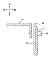
- the recess 21 is formed with a hook 23 that engages with the upper end portion of the circuit board 17 as shown in FIG. 6 when the circuit board 17 is inserted to the bottom of the recess 21.
- 6 is a cross-sectional view taken along the line VI-VI in FIG. 5, but is drawn with the configuration ahead of the hook 23 omitted.
- the hook 23 is provided at the tip of a leaf spring portion 24 formed by making a cut 25 in the case 20 so as to protrude rightward in a hook shape.
- a flat plate-like support portion 27 that is orthogonal to the vertical direction protrudes from the lower right side of the case 20.
- a second bearing portion 50 that receives a shaft portion 33 that protrudes forward from the plate portion 31 and a first bearing portion 40 that receives a shaft portion 34 that protrudes rearward from the plate portion 31 are provided. It has been.
- the plate portion 31 is configured as a rectangular plate having a long shape in the front-rear direction, and rectangular cutout portions 31B are formed at both ends of one long side (the lower long side in FIG. 5). Is formed.
- a shaft portion 33 is formed in the front cutout portion 31B so as to protrude forward along the long side.
- a shaft part 34 is formed in the rear cutout 31B so as to protrude rearward along the long side.
- Each of the shaft portions 33 and 34 is configured as a series of shaft portions in which the respective axis lines are arranged in the same straight line, and is configured in a cylindrical shape having the same diameter as the thickness of the plate portion 31 except for the end portions. Yes.
- the tip vicinity portion 33A of the shaft portion 33 is notched from both sides in the diametrical direction and is formed in a flat plate shape, but the tip portion 33B (an example of the second end portion) of the shaft portion 33 is a hemisphere without being cut out. Configured.
- the tip end portion 34A and the tip end portion 34B (an example of the first end portion) of the shaft portion 34 are notched from both sides in the diametrical direction and are formed in a series of flat plate shapes. It has a flat plate shape (so-called SR shape) cut out from both sides in the direction.
- the tip vicinity portion 33A of the shaft portion 33 and the tip vicinity portion 34A and the tip portion 34B of the shaft portion 34 are configured in a flat plate shape, and the normal direction of the flat plate is the normal line of the plate portion 31.
- the direction is orthogonal to the direction.
- subjected the reference number of the 40th series or the 50th series demonstrated below is integrally molded with the case 20, the support part 27, and resin.
- this resin is made of a material different from the resin in which the plate portion 31 and the shaft portions 33 and 34 are integrally formed in order to reduce the frictional noise between them.
- the first bearing portion 40 includes a slit 41, a first defining portion 42, and a guide surface 43.
- the slit 41 is narrower than the diameter of the shaft portion 34, and has a width in which the tip vicinity portion 34A and the tip portion 34B can be inserted when the normal direction of the tip vicinity portion 34A and the tip portion 34B is directed in the left-right direction. have.
- regulation part 42 is arrange
- the guide surface 43 is formed in a cylindrical surface below the slit 41, and supports the tip vicinity portion 34A and the tip portion 34B so as to be rotatable around the axis. Further, a pedestal 47 protruding in a rectangular parallelepiped shape is formed on the upper surface of the support portion 27 in front of the slit 41 and the guide surface 43.
- the first bearing portion 40 configured in this way has the tip vicinity portion 34A and the tip portion 34B in a state where the normal direction of the tip vicinity portion 34A and the tip portion 34B is directed in the left-right direction as shown in FIG. It is inserted into the slit 41. Subsequently, when the shaft portion 34 is rotated around the axis, the first bearing portion 40 can support the shaft portion 34. At this time, as shown in FIG. 9, the cylindrical portion of the shaft portion 34 in front of the tip vicinity portion 34 ⁇ / b> A comes into contact with the pedestal 47, whereby the position of the axis of the shaft portion 34 in the guide surface 43 (in the radial direction). Position) is defined.
- the tip end portion 34B comes into contact with the front surface of the first defining portion 42, and the position of the shaft portion 34 in the front-rear direction (that is, the thrust direction) is defined. .
- the second bearing portion 50 is also provided with a slit 51 and a guide surface 53 like the first bearing portion 40, but instead of the first defining portion 42, a second defining portion is provided. 52.
- the slit 51 is narrower than the diameter of the shaft portion 33 and has a width in which the tip vicinity portion 33A can be inserted when the normal direction of the tip vicinity portion 33A is directed in the left-right direction.
- the guide surface 53 is formed in a cylindrical surface below the slit 51, and supports the tip vicinity portion 33A so as to be rotatable around the axis.
- a pedestal 57 protruding in a rectangular parallelepiped shape is formed on the upper surface of the support portion 27 behind the slit 51 and the guide surface 53. The front of the pedestal 57 is a space in which the support portion 27 is vertically penetrated, and a second defining portion 52 that urges the distal end portion 33B rearward as described below is disposed at the front end of the portion. Has been.
- the second defining portion 52 includes a first portion 52A extending upward along the front end of the case 20, a second portion 52B extending while curving downward and obliquely downward from the upper end of the first portion 52A, and the rear of the second portion 52B. And a third portion 52C extending downward from the end.
- the connecting portion between the second portion 52B and the first portion 52A or the third portion 52C, and the second portion 52B itself are elastically deformed.
- the third portion 52C is configured in a flat plate shape orthogonal to the front-rear direction.
- the distance between the front surface of the first defining portion 42 and the rear surface of the third portion 52C is slightly smaller than the distance between both ends of the tip portions 33B and 34B. Designed.
- the insertion elastically deforms the second defining portion 52. It is made while. Then, after the insertion, the distal end portion 33 ⁇ / b> B of the shaft portion 33 receives a backward biasing force from the third portion 52 ⁇ / b> C of the second defining portion 52. As a result, the distal end portion 34B of the shaft portion 34 comes into contact with the front surface of the first defining portion 42.
- the cylindrical portion of the shaft portion 33 on the rear side of the tip vicinity portion 33 ⁇ / b> A contacts the pedestal 57, thereby defining the position of the axis of the shaft portion 33 in the guide surface 53 (position in the radial direction). Is done.
- the shaft portions 33 and 34 can move in the radial direction.
- the portion 33, 34 is turned upward around the axis, movement in the radial direction is restricted. That is, the guide surfaces 43 and 53 and the bases 47 and 57 correspond to an example of a guide.
- a pair of locking portions 55 are formed integrally with the third portion 52C immediately above the contact portion of the third portion 52C with the tip portion 33B in that state.
- the locking portion 55 is provided at a symmetrical position with respect to a surface extending upward from the axis of the shaft portions 33 and 34, and is configured in a rib shape extending in the vertical direction.
- the upper and lower end surfaces of each locking portion 55 are chamfered in an arc shape when viewed in the front-rear direction. Therefore, when the tip vicinity portion 33A is inserted into the slit 51, the tip portion 33B is guided between the two while pressing the pair of locking portions 55 forward, and the tip vicinity portion 33A passes through the slit 51. After that, as shown in FIG. 11, the locking portion 55 comes into contact with the tip portion 33B from the upper right and upper left, respectively.
- a locking piece 59 configured in a flat plate shape perpendicular to the front-rear direction protrudes.
- the locking piece 59 protrudes to a height that crosses the axis of the shaft portions 33 and 34, and the plate portion 31 is formed with a notch 39 that receives the locking piece 59.
- the notch 39 is locked regardless of the position where the plate 31 rotates about the axis when the shafts 33 and 34 are in contact with the third portion 52C and the first defining portion 42.
- the piece 59 is configured to be in a non-contact size.
- the cutout portion 39 causes the elastic deformation to occur in the second defining portion 52. It is configured to have a size that interferes with the locking piece 59 before exceeding the allowable range.
- the operation portion 13 is mounted on the plate portion 31 on the side closer to the free end than the notch portion 31 ⁇ / b> B from the side opposite to the side from which the protruding portion 36 protrudes.
- a pair of square holes 32 is formed in the portion, and the pair of hooks 13 ⁇ / b> A formed in the operation portion 13 are engaged with the square holes 32 while being elastically deformed, whereby the operation portion 13 is attached to the plate portion 31. Is done.
- the peripheral edge 13B of the operating portion 13 protrudes in the same direction as the protruding direction of the hook 13A, and the peripheral edge 13B engages with the front and rear end edges 31A of the plate portion 31 from the outer periphery.
- each square hole 32 has a large-diameter portion 32A on the back side with respect to the insertion direction of the hook 13A, and a hook-shaped head in each hook 13A engages with each large-diameter portion 32A.
- the operation portion 13 is connected to the plate portion 31 without a gap, and the operations of both are integrated.
- the shaft portions 33 and 34 and the operation unit 13 operate integrally, and the operation on the tactile switch 15 as described above becomes possible.
- the distal end portion 33B of the shaft portion 33 receives a backward biasing force from the third portion 52C of the second defining portion 52, and as a result, the distal end portion 34B of the shaft portion 34 is obtained. Comes into contact with the front surface of the first defining portion 42. For this reason, the position in the thrust direction of the shaft portions 33 and 34 is stably maintained at a position where the tip end portion 34 ⁇ / b> B contacts the front surface of the first defining portion 42. For this reason, the operation part 13 which operates integrally with the shaft parts 33 and 34 can also reduce the play in the thrust direction.
- the urging force is applied by a spring or the like
- the urging force is applied by a second defining portion 52 integrally formed with the first bearing portion 40 and the second bearing portion 50 or the like. is doing.
- a so-called resin spring the spring force (that is, the biasing force) can be easily adjusted in the present embodiment.
- the radial position of the shaft portion 33 is defined by the guide surface 53 and the pedestal 57, and the radial position of the shaft portion 34 is defined by the guide surface 43 and the pedestal 47. Further, the pair of locking portions 55 abut on the tip portion 33B from above to below (in a specific direction), so that the shaft portion 33 moves upward (in a direction opposite to the specific direction) from the guide surface 53. Suppresses withdrawal. For this reason, the structure for reducing the play in the thrust direction in the operation unit 13 as described above is stably maintained.
- the operating device 10 reduces the backlash in the thrust direction by using the restoring force from the elastic deformation of the second defining portion 52. For this reason, for example, compared with the case where the backlash is reduced by the case or the like coming into contact with the front and rear ends (thrust direction end surfaces) of the operation unit 13, it is also suppressed that the operation unit 13 is difficult to rotate due to friction. .
- the pair of locking portions 55 are in contact with the tip 33B from the upper right and upper left at two points across a surface extending upward (opposite to the specific direction) from the axis. For this reason, the center position of the front end portion 33B is defined by the pair of locking portions 55, and the configuration for reducing the play in the thrust direction can be more stably maintained. Further, since the shaft portion 33 abuts against the pedestal 57 at the lower side, the shaft portion 33 is supported from three different directions around the axis, and the center position is further stabilized. Since the locking portion 55 is integrally formed with the third portion 52C, the device configuration can be simplified.
- the cutout portion 39 causes the elastic deformation to occur in the second defining portion. It interferes with the locking piece 59 until the allowable range at 52 is exceeded. For this reason, even if a forward external force is applied to the operation unit 13, it is favorable that the plate part 31 moves forward beyond the elastic deformation allowable range in the second defining part 52 and the second defining part 52 is damaged. Can be suppressed. Further, the notch portion 39 is different from the plate portion 31 in a state where the shaft portions 33 and 34 are sandwiched between the second defining portion 52 and the first defining portion 42 regardless of the rotating state of the plate portion 31. Since the contact pieces 59 are not in contact with each other, it is also possible to prevent the locking pieces 59 from inhibiting the rotation of the plate portion 31 and the operation portion 13.
- the guide surface 43 and the pedestal 47 are provided at a position closer to the first defining portion 42 than an intermediate point between the first defining portion 42 and the second defining portion 52, and the guide surface 53 and the pedestal 57 are arranged in the middle. It is provided at a position closer to the second defining portion 52 than the point. For this reason, the radial position of both ends (that is, the tip portion 33B and the tip portion 34B) of the shaft portions 33 and 34 as the shaft portions in the embodiment is well defined, and the play in the thrust direction is reduced. The configuration can be maintained more stably.
- each part constituting the first bearing part 40, each part constituting the second bearing part 50, pedestals 47 and 57, and the locking piece 59 are made of resin integrally with the case 20 via the support part 27. It is molded with. For this reason, in the operating device 10, the effect of maintaining the axis line in a desired position while maintaining the positional relationship of the respective parts well and reducing the play is stably exhibited. Moreover, the accuracy of the relative position of each part can be easily improved by being integrally molded in this way.
- the operation device 10 is mounted on the vehicle 1, and the operation unit 13 rotates around an axis line that coincides with the front-rear direction of the vehicle 1. If backlash in the front-rear direction is present in the operation unit mounted on the vehicle 1, the position of the operation unit may fluctuate during acceleration / deceleration of the vehicle 1, and the operability and feeling of the operation unit may be reduced. In the operation device 10, it is possible to reduce the play in the thrust direction (that is, the front-rear direction of the vehicle 1) of the operation unit 13 while suppressing the operation unit 13 from being difficult to rotate due to friction. While maintaining the smoothness of the movement, it is possible to suppress the decrease in the operability or feeling as described above.
- the operating device 10 of the present embodiment is provided on the upper surface of the console 9 so that the driver can keep his left hand H during driving, it suppresses backlash in the thrust direction as described above.
- the effect of suppressing the decrease in feeling appears more remarkably. Further, such an effect becomes more prominent in a high-class vehicle with little vibration inside the passenger compartment 3.
- Such an effect may occur even if the direction of the axis and the longitudinal direction of the vehicle 1 do not completely match.
- the direction of the axis is disposed within a cone whose angle with the longitudinal direction of the vehicle 1 is within 45 °, the above-described effect may occur in the same manner. That is, if the axis is arranged so that the direction of the axis substantially coincides with the front-rear direction of the vehicle 1, the above-described effect may occur in the same manner.
- the portion of the tip 34B that contacts the first defining portion 42 is spherical, and the front surface of the first defining portion 42 that contacts the first defining portion 42 is planar. Further, a portion of the tip end portion 33B that contacts the third portion 52C is spherical, and a rear surface of the third portion 52C that contacts the third portion 52C is planar. Accordingly, the contact between the two contacting each other becomes a point contact, and the friction is reduced, so that the operation portion 13 can be rotated more smoothly.
- the pair of locking portions 55 abut on the tip end portion 33B at two points from the upper right and upper left, but is not limited thereto.
- the locking portion may be provided on the third portion 52C as a substantially rectangular parallelepiped protrusion including the pair of locking portions 55 in the embodiment.
- the locking portion comes into contact with the tip portion 33B at one upper point.
- the center position of the distal end portion 33B can be stabilized when the locking portion 55 contacts at two points as in the embodiment.
- the pair of shaft portions 33 and 34 are protruded from the front and rear ends of the plate portion 31, but the present invention is not limited to this.
- the shaft portion may be a single metal rod or the like, and in that case, the plate portion 31 may be connected to the metal rod with a screw or the like.
- the operation device 10 is applied to the operation unit 13 that is mounted on a vehicle and presses the tactile switch 15, but is not limited thereto.
- the operation device can be applied to a rotary operation unit or the like that is provided in a trunk or the like to release the lock.
Landscapes
- Rotary Switch, Piano Key Switch, And Lever Switch (AREA)
Abstract
操作装置は、所定の軸線を中心に回動する操作部(13)と、前記軸線に沿って相反する方向に突出した第1端部(34B)と第2端部(33B)とを有し、前記操作部と一体に動作する軸部(33,34)と、を備える。ガイド(43,47,53,57)は、前記軸部のラジアル方向への移動を規制する。第1規定部(42)は、前記軸部の前記第1端部に当接してスラスト方向の位置を規定する。第2規定部(52)は、前記第2端部に圧接され、前記第1端部を前記第1規定部に当接させる。係止部(55)は、前記第2規定部に一体に設けられ、前記第2端部に当接して前記軸部が前記ガイドから離脱することを抑制する。
Description
本出願は、2015年3月6日に出願された日本特許出願2015-44794号に基づくもので、ここにその記載内容を援用する。
本開示は、所定の軸線を中心に回動する操作部を備えた操作装置に関する。
従来、所定の軸線を中心に回動する操作部を備えた操作装置として、当該操作部が操作者によって押圧されることによって回動し、かつ、その操作部が電気的接点を開閉するスイッチに連動したものが提案されている。例えば、操作部としてのキースイッチ本体の上端に挿通孔を設け、その挿通孔にヒンジ軸を通すことで前記キースイッチ本体を指で押圧して回動させられるようにして、前記キースイッチ本体を介してマイクロスイッチを押圧する操作装置が提案されている(例えば、特許文献1参照)。
特許文献1に記載の操作装置では、操作部としてのキースイッチ本体が、ヒンジ軸の中心を通る軸線を中心に回動する。しかしながら、この種のスイッチに係る操作装置では、操作部がスラスト方向(すなわち、軸線に平行な方向)に不必要に移動してしまういわゆるガタを軽減する試みがなされてこなかった。このようなガタを軽減するためには、操作部のスラスト方向両端面にケーシング等の端面を密接させることが考えられるが、あまり密接させすぎると摩擦により操作部が回動しにくくなる。一方、前記密接の度合いが緩すぎると、前記ガタは十分に軽減されない場合がある。
このように、従来の操作装置では、操作部の回動に伴う摩擦の発生を抑制しつつ、前記操作部のスラスト方向のガタを軽減する必要が生じ得る。また、電気的接点を開閉するスイッチとは関連のない他の用途の操作装置においても、同様の必要が生じ得る。
本開示は、所定の軸線を中心に回動する操作部を備えた操作装置の提供を目的としており、操作部の回動に伴う摩擦の発生を抑制しつつ、前記操作部のスラスト方向のガタを軽減する。
本開示の一態様において、操作装置は、操作者によって押圧されることにより、所定の軸線を中心に回動する操作部と、軸線に沿って設けられ、当該軸線に沿って相反する方向に突出した第1端部と第2端部とを有し、操作部と一体に動作する軸部と、軸部の一部を特定方向に挿入され、挿入された軸部のラジアル方向への移動を規制するガイドと、ガイドに挿入された軸部の第1端部にスラスト方向から当接し、軸部のスラスト方向の位置を規定する第1規定部と、ガイドへの軸部の挿入時に弾性変形することによって、当該弾性変形からの復元力により軸部の第2端部にスラスト方向から圧接され、軸部の第1端部を第1規定部に当接させる第2規定部と、第2規定部に一体に設けられ、挿入後の軸部の第2端部に当接することにより、軸部がガイドから特定方向とは逆方向に移動して離脱するのを抑制する係止部と、を備える。
このように構成された操作装置では、操作部における回動の軸線に沿って設けられた軸部の一部は、特定方向にガイドへ挿入され、そのガイドは、挿入された軸部のラジアル方向(すなわち、軸線に直交する方向)への移動を規制する。このとき、第1規定部は、ガイドに挿入された軸部の第1端部にスラスト方向から当接し、軸部のスラスト方向の位置を規定する。また、このとき、第2規定部は、前記一部のガイドへの挿入時に弾性変形することによって、当該弾性変形からの復元力により軸部の第2端部にスラスト方向から圧接される。すると、軸部の第1端部は第1規定部に良好に当接される。このため、軸部のスラスト方向の位置は、第1端部が第1規定部に当接する位置に安定して維持される。このため、軸部と一体に動作する操作部も、スラスト方向のガタを軽減される。
また、第2規定部に一体に設けられた係止部は、ガイドへの挿入後の軸部の第2端部に当接することにより、軸部がガイドから特定方向とは逆方向に移動して離脱するのを抑制する。このため、前述のように操作部のスラスト方向のガタを軽減するための構成が、安定して維持される。しかも、第2規定部の弾性変形からの復元力を利用してスラスト方向のガタを軽減しているので、摩擦によって操作部が回動しにくくなることも抑制される。更に、係止部が第2規定部と一体に構成されたことにより、装置構成も簡略化することができる。
本開示についての上記およびその他の目的、特徴や利点は、添付の図面を参照しながら下記の詳細な記述により、より明確になる。
実施形態にかかる操作装置を車室内側方から示す説明図である。
操作装置の配置を上方から示す説明図である。
操作装置の操作方法を概略的に示す説明図である。
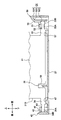
図3のIV-IV線における断面を概略的に示す図である。
操作装置を示す分解斜視図である。
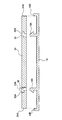
図5のVI-VI線における断面図である。
図5のVII-VII線における断面図である。
第1軸受け部の軸部装着時の状態を示す図5のIIX方向矢視図である。
第1軸受け部の軸部装着後の状態を示す図5のIIX方向矢視図である。
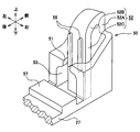
操作装置の第2軸受け部を示す拡大斜視図である。
第2軸受け部の係止部の効果を示す説明図である。
図5のXII-XII線における断面図である。
実施形態について、図面を用いて説明する。
図1,図2に示すように、実施形態の操作装置10が設けられた車両1は、車室3の内部に設けられた運転席5と助手席7との間にコンソール9を備えている。操作装置10は、コンソール9の上面に設けられている。図3に示すように、操作装置10は、筐体11の右側面から突出した操作部13を備えている。操作部13は、運転席5に着座した運転者(図示省略:操作者の一例)が、左手Hの親指Fにより、矢印Pで示すように筐体11の内側方向に押し込むことができる。
以下、操作装置10がこのように設置された場合における車両1の前後左右上下を、便宜上、操作装置10における前後左右上下と呼ぶ場合がある。但し、これらの各方向は、操作装置10を構成する各部の相対的な位置関係を簡潔に説明するために規定した方向にすぎない。実際に操作装置10が利用されるに当たって、それがどのような方向に向けられるかは任意である。
図4に概略的に示すように、筐体11の内部には、タクタイルスイッチ15が実装された回路基板17が配設されている。また、操作部13が接続された板部31は、軸部33,34の軸線を中心に回動可能に構成されている。板部31には、タクタイルスイッチ15との対向位置(厳密には、タクタイルスイッチ15の押しボタンとの対向位置)に、突部36が設けられている。このため、操作部13が前述のように押し込まれると、板部31及び突部36が軸部33,34の軸線を中心に回動し、突部36によってタクタイルスイッチ15の押しボタンが押圧される。なお、図4~図6では、タクタイルスイッチ15のうち、押しボタンのみを図示して参照符号15を付している。
また、親指Fが操作部13から離れるなどして、前述のように操作部13を押し込んでいる親指Fからの押圧力がなくなると、タクタイルスイッチ15において押しボタンに加わる復元力により、操作部13も押圧前の位置へ戻る。
図5は、回路基板17及び操作部13の支持機構の構成を表す分解斜視図である。図5に示すように、この支持機構は、ケース20を中心に構成されている。ケース20の右側面には、回路基板17を受け入れる矩形の凹部21が、ケース20の上端部から形成されている。凹部21は、左右方向の長さ(すなわち深さ)は回路基板17の左右方向の長さ(すなわち厚さ)よりも長く、上下方向の長さは回路基板17の上下方向の長さよりも長いが、前後方向の長さは回路基板17の前後方向の長さよりも短い。凹部21の前後両内壁面には、回路基板17の厚さと同じ幅の矩形の溝22が、それぞれ上下方向に形成されている。この2つの溝22の深さと凹部21の前後方向の長さとを合わせた長さが、回路基板17の前後方向の長さよりも若干長くなっている。このため、回路基板17は、前後端縁を溝22に嵌合させて凹部21に上方から挿入することができる。
また、凹部21には、回路基板17が凹部21の最下部まで挿入されたときに、図6に示すように回路基板17の上端部に係合するフック23が形成されている。なお、図6は図5のVI-VI線断面図であるが、フック23よりも前方の構成を省略して描かれている。このフック23は、ケース20に切り込み25を入れて構成された板バネ部24の先端に、右方に鉤状に突出して設けられている。回路基板17が凹部21へ挿入される際には、板バネ部24を弾性変形させることによってフック23を後退(すなわち左へ変位)させながら挿入がなされ、挿入完了後に、図6に示すようにフック23が回路基板17の上端部に係合する。この係合によって、回路基板17及びその回路基板17に設けられたタクタイルスイッチ15は、ケース20に対して良好に位置決めされる。
図5に戻って、ケース20の下端右辺からは、上下方向に対して直交する平板状の支持部27が突出して設けられている。この支持部27の上面には、板部31から前方に突出した軸部33を受ける第2軸受け部50と、板部31から後方に突出した軸部34を受ける第1軸受け部40とが設けられている。
ここで、板部31は、概略的な形状が前後方向に長辺を有する長方形板状に構成され、1つの長辺(図5における下方の長辺)の両端部に矩形の切欠部31Bを形成されている。前側の切欠部31Bには、前記長辺に沿って軸部33が前方に突出して形成されている。後側の切欠部31Bには、前記長辺に沿って軸部34が後方に突出して形成されている。各軸部33,34は、互いの軸線が同一直線状に配設される一連の軸部として構成され、端部を除いて、板部31の厚さと同じ直径を有する円柱状に構成されている。
軸部33の先端近傍部33Aは、直径方向両側から切り欠かれて平板状に構成されているが、軸部33の先端部33B(第2端部の一例)は、切り欠かれることなく半球状に構成されている。軸部34の先端近傍部34A及び先端部34B(第1端部の一例)は直径方向両側から切り欠かれて一連の平板状に構成され、そのうち先端部34Bは、半球状の部材を前記直径方向両側から切り欠いて平板状にした形状(いわゆるSR形状)を有している。このように、軸部33の先端近傍部33Aと軸部34の先端近傍部34A及び先端部34Bとは、平板状に構成されているが、その平板の法線方向は板部31の法線方向と直交する方向とされている。
次に、第1軸受け部40,第2軸受け部50等の構成を説明する。なお、以下に説明する40番台又は50番台の参照符号を付した各構成は、ケース20及び支持部27と樹脂にて一体成形されている。但し、この樹脂は、板部31及び軸部33,34を一体成形している樹脂とは異なる素材であった方が、両者の摩擦音を軽減する上で好ましい。
図7,図8に示すように、第1軸受け部40は、スリット41と第1規定部42とガイド面43とを備えている。スリット41は、軸部34の直径よりも狭く、かつ、先端近傍部34A及び先端部34Bの前記法線方向を左右方向に向けたときに当該先端近傍部34A及び先端部34Bを挿入可能な幅を有している。第1規定部42は、スリット41の後方に配設され、前後方向に対して直交する平板状に構成されている。ガイド面43は、スリット41の下方において円筒面状に構成され、先端近傍部34A及び先端部34Bを前記軸線回りに回転可能に支持する。更に、スリット41及びガイド面43の前方における支持部27の上面には、直方体状に突出した台座47が形成されている。
このように構成された第1軸受け部40は、先端近傍部34A及び先端部34Bの前記法線方向を図8に示すように左右方向に向けた状態で当該先端近傍部34A及び先端部34Bがスリット41に挿入される。続いて軸部34が軸線回りに回転されることにより、第1軸受け部40は、軸部34を支持可能となる。このとき、図9に示すように、先端近傍部34Aよりも前側の軸部34における円筒状部分が台座47に当接することにより、ガイド面43内における軸部34の軸線の位置(ラジアル方向の位置)が規定される。また、軸部34が後述のように後方に付勢されると、先端部34Bが第1規定部42の前面に当接し、軸部34の前後方向(すなわちスラスト方向)の位置が規定される。
図7,図10に示すように、第2軸受け部50も、第1軸受け部40と同様にスリット51とガイド面53とを備えているが、第1規定部42に代えて第2規定部52を備えている。スリット51は、軸部33の直径よりも狭く、かつ、先端近傍部33Aの前記法線方向を左右方向に向けたときに当該先端近傍部33Aを挿入可能な幅を有している。ガイド面53は、スリット51の下方において円筒面状に構成され、先端近傍部33Aを前記軸線回りに回転可能に支持する。スリット51及びガイド面53の後方における支持部27の上面には、直方体状に突出した台座57が形成されている。台座57の前方は、支持部27が上下に貫通された空間となっており、その部分の前端に、以下に説明するように先端部33Bを後方に付勢する第2規定部52が配設されている。
第2規定部52は、ケース20の前端に沿って上方へ延びる第1部分52Aと、第1部分52Aの上端から後斜め下方へ湾曲しながら延びる第2部分52Bと、第2部分52Bの後端から下方へ延びる第3部分52Cとを備えている。この第2規定部52は、第2部分52Bと第1部分52A又は第3部分52Cとの連接部、並びに、当該第2部分52B自身が弾性変形する。第3部分52Cは、前後方向に対して直交する平板状に構成されている。また、第2規定部52に外力が加わっていない状態では、第1規定部42の前面と第3部分52Cの後面との間隔が先端部33B,34Bの両端の間隔よりも若干小さくなるように設計されている。
このため、先端部34B及び先端近傍部34A,33Aの前記法線方向を左右方向に向けた状態でそれらがスリット41,51に挿入されると、その挿入は第2規定部52を弾性変形させながらなされる。すると、当該挿入後に、軸部33の先端部33Bは第2規定部52の第3部分52Cから後方への付勢力を受ける。その結果、軸部34の先端部34Bが第1規定部42の前面に当接する。また、このとき、先端近傍部33Aよりも後側の軸部33における円筒状部分が台座57に当接することにより、ガイド面53内における軸部33の軸線の位置(ラジアル方向の位置)が規定される。なお、先端部34B及び先端近傍部34A,33Aがスリット41,51に挿入された状態では、軸部33,34はラジアル方向へ移動可能であるが、当該挿入後に板部31が多少なりとも軸部33,34の軸線回りに上方へ回動されると、前記ラジアル方向への移動が規制される。すなわち、ガイド面43,53及び台座47,57がガイドの一例に相当する。
また、その状態における第3部分52Cの先端部33Bへの当接箇所直上には、一対の係止部55が当該第3部分52Cと一体に形成されている。この係止部55は、軸部33,34の軸線から上方に伸ばした面に対して対称の位置に設けられ、上下方向に延びるリブ状に構成されている。各係止部55の上下の端面は、前後方向に見て円弧状に面取りされている。このため、先端近傍部33Aがスリット51に挿入される際には、先端部33Bは一対の係止部55を前方に押圧しながら両者の間を案内され、先端近傍部33Aがスリット51を通過した後は、図11に示すように、係止部55は先端部33Bに右上方及び左上方からそれぞれ当接する。
図5,図7に示すように、支持部27の上面における台座47と台座57との間には、前後方向に対して直交する平板状に構成された係止片59が突出している。この係止片59は、軸部33,34の軸線を横切る高さまで突出し、板部31には、その係止片59を受け入れる切欠部39が形成されている。切欠部39は、軸部33,34が第3部分52Cと第1規定部42とに接触している状態では、板部31が前記軸線を中心にしてどの位置へ回動しても係止片59とは非接触となる大きさに構成されている。また、切欠部39は、板部31が第2規定部52を弾性変形させながら前方に移動して、第1規定部42から先端部34Bが離れた場合、前記弾性変形が第2規定部52における許容範囲を超えるまでに係止片59と干渉する大きさに構成されている。
板部31における切欠部31Bよりも自由端側の部分には、図5,図12に示すように、突部36が突出した側とは反対側から操作部13が装着されている。当該部分には一対の角穴32が形成され、操作部13に形成された一対のフック13Aが弾性変形しながら当該角穴32にそれぞれ係合することにより、操作部13は板部31に装着される。また、図12に示すように、操作部13の周縁部13Bはフック13Aの突出方向と同方向に突出しており、板部31における前後側の端縁31Aに周縁部13Bが外周から係合する。更に、各角穴32はフック13Aの挿入方向に対して奥側が大径部32Aとなっており、各フック13Aにおける鉤状の頭部が各大径部32Aに係合する。このような係合がなされると、操作部13は板部31に隙間なく接続され、両者の動作が一体になる。その結果、軸部33,34と操作部13とも一体に動作し、前述のようなタクタイルスイッチ15に対する操作が可能となる。
実施形態によれば、以下の効果が得られる。
[1A]前述のように、操作装置10では、軸部33の先端部33Bは第2規定部52の第3部分52Cから後方への付勢力を受け、その結果、軸部34の先端部34Bが第1規定部42の前面に当接する。このため、軸部33,34のスラスト方向の位置は、先端部34Bが第1規定部42の前面に当接する位置に安定して維持される。このため、軸部33,34と一体に動作する操作部13も、スラスト方向のガタを軽減される。
また、前記付勢力はスプリング等によって付与することも考えられるが、本実施形態では、第1軸受け部40及び第2軸受け部50等と一体成形された第2規定部52によって前記付勢力を付与している。このため、スプリング等を利用する場合に比べて、装置構成を簡略化して部品点数及び製造コストを低減することができる。また、このようないわゆる樹脂バネを利用することにより、本実施形態ではバネ力(すなわち前記付勢力)の調整が容易になる。
[1B]また、ガイド面53及び台座57によって軸部33のラジアル方向の位置が規定され、ガイド面43及び台座47によって軸部34のラジアル方向の位置が規定される。更に、一対の係止部55は、先端部33Bに上方から下方に(特定方向に)当接することにより、軸部33が上方向(特定方向とは逆方向)に移動してガイド面53から離脱するのを抑制する。このため、前述のように操作部13におけるスラスト方向のガタを軽減するための構成が、安定して維持される。
[1C]しかも、操作装置10では、第2規定部52の弾性変形からの復元力を利用して前記スラスト方向のガタを軽減している。このため、例えば操作部13の前後端(スラスト方向端面)に筐体等が当接することによってガタが軽減される場合に比べて、摩擦によって操作部13が回動しにくくなることも抑制される。
[1D]一対の係止部55は、前記軸線から上方(特定方向とは逆方向)に延ばした面を挟んだ2点で、先端部33Bに右上方及び左上方からそれぞれ当接する。このため、先端部33Bの中心位置は一対の係止部55によって規定され、前記スラスト方向のガタを軽減するための構成を一層安定して維持することができる。更に、軸部33は下方で台座57に当接するので、軸部33は軸線回りの異なる三方から支持され、前記中心位置は一層安定する。係止部55が第3部分52Cと一体に構成されたことにより、装置構成も簡略化することができる。
[1E]また、操作装置10では、操作部13が押圧されなくなるとタクタイルスイッチ15において押しボタンに加わる復元力により操作部13も押圧前の位置へ戻る。このため、操作装置10の全体としての構成を簡略化し、その製造コストを低減することができる。
[1F]切欠部39は、板部31が第2規定部52を弾性変形させながら前方に移動して、第1規定部42から先端部34Bが離れた場合、前記弾性変形が第2規定部52における許容範囲を超えるまでに係止片59と干渉する。このため、操作部13に前向きの外力が加わっても、板部31が第2規定部52における弾性変形の許容範囲を超えて前方に移動して第2規定部52が破損するのを、良好に抑制することができる。また、切欠部39は、軸部33,34が第2規定部52と第1規定部42との間に挟まれている状態では、板部31の回動状態に拘わらず板部31とは非接触となるので、係止片59が板部31及び操作部13の回動を阻害することも抑制される。
[1G]ガイド面43及び台座47は、第1規定部42と第2規定部52との中間点よりも第1規定部42に近い位置に設けられ、ガイド面53及び台座57は、前記中間点よりも第2規定部52に近い位置に設けられている。このため、前記実施形態における軸部としての軸部33,34の両端(すなわち、先端部33B,先端部34B)のラジアル方向の位置が良好に規定され、前記スラスト方向のガタを軽減するための構成を一層安定して維持することができる。
[1H]第1軸受け部40を構成する各部と、第2軸受け部50を構成する各部と、台座47,57と、係止片59とは、支持部27を介してケース20と一体に樹脂にて成形されている。このため、操作装置10では、前記各部の位置関係を良好に維持して、前記ガタを軽減しつつ前記軸線を所望の位置に維持する効果が安定して発揮される。また、このように一体成形されたことにより、各部の相対位置の精度も容易に向上させることができる。
[1I]操作装置10は、車両1に搭載され、操作部13は、車両1の前後方向と一致する軸線を中心に回動する。車両1に搭載される操作部において前後方向のガタが存在すると、車両1の加減速時に当該操作部の位置が変動して当該操作部の操作性やフィーリングが低下する可能性がある。操作装置10では、摩擦によって操作部13が回動しにくくなるのを抑制しつつ当該操作部13の前記スラスト方向(すなわち車両1の前後方向)のガタを軽減することができるので、操作部13の動きの円滑性を保持したままで前述のような操作性又はフィーリングの低下を抑制することができる。
特に、本実施形態の操作装置10は、運転者が運転の最中もずっと左手Hを置いておけるようにコンソール9の上面に設けられているので、前述のようにスラスト方向のガタを抑制してフィーリングの低下を抑制する効果が一層顕著に表れる。そして、更に、このような効果は、車室3の内部における振動の少ない高級車であれば一層顕著に表れる。
なお、このような効果は、前記軸線の方向と車両1の前後方向とが完全に一致していなくても生じる場合がある。例えば、前記軸線の方向は、車両1の前後方向となす角度が45°以内の円錐内に配設されていれば、前記効果が同様に生じる場合がある。すなわち、前記軸線の方向が車両1の前後方向とほぼ一致するように配設されていれば、前記効果が同様に生じる場合がある。
[1J]先端部34Bにおける第1規定部42と当接する部分は球面状で、それに当接する第1規定部42の前面は平面状である。また、先端部33Bにおける第3部分52Cと当接する部分は球面状で、それに当接する第3部分52Cの後面は平面状である。従って、前記当接し合う両者の接触がそれぞれ点接触となって摩擦が少なくなるため、操作部13は一層円滑に回動することができる。
以上、実施形態について説明したが、本開示は前記実施形態に限定されることなく、種々の形態を採り得る。
[2A]前記実施形態では、一対の係止部55は、先端部33Bに右上方及び左上方から2点で当接するが、これに限定されるものではない。例えば、係止部は、前記実施形態における一対の係止部55を包含する略直方体状の突起として、第3部分52Cに設けられてもよい。但し、この場合、係止部が先端部33Bに上方の1点で接触することになる。前記実施形態のように係止部55が2点で接触した方が、先端部33Bの中心位置を安定させることができる。
[2B]前記実施形態では、一対の軸部33,34を板部31の前後両端から突出させているが、これに限定されるものではない。例えば、軸部は1本の金属棒等であってもよく、その場合、板部31はビス等で当該金属棒に接続されてもよい。
[2C]前記実施形態では、操作装置10を、車両に搭載されてタクタイルスイッチ15を押圧するための操作部13に適用しているが、これに限定されるものではない。例えば、操作装置は、トランク等に設けられてロックの解除を行うための回動型の操作部等に対しても適用することができる。
[2D]また、前記実施形態における係止片59及び切欠部39は省略されてもよく、その場合も、前述の[1A]~[1E]及び[1G]~[1J]の効果は同様に生じる。
[2E]前記実施形態における1つの構成要素が有する機能を複数の構成要素として分散させたり、複数の構成要素が有する機能を1つの構成要素に統合させたりしてもよい。また、前記実施形態の構成の一部を省略してもよい。また、前記実施形態の構成の少なくとも一部を、他の実施形態の構成に対して付加又は置換してもよい。なお、特許請求の範囲に記載した文言のみによって特定される技術思想に含まれるあらゆる態様が本開示に包含される。
Claims (9)
- 操作者によって押圧されることにより、所定の軸線を中心に回動する操作部(13)と、
前記軸線に沿って設けられ、当該軸線に沿って相反する方向に突出した第1端部(34B)と第2端部(33B)とを有し、前記操作部と一体に動作する軸部(33,34)と、
前記軸部の一部を特定方向に挿入され、挿入された前記軸部のラジアル方向への移動を規制するガイド(43,47,53,57)と、
前記ガイドに挿入された前記軸部の前記第1端部にスラスト方向から当接し、前記軸部のスラスト方向の位置を規定する第1規定部(42)と、
前記ガイドへの前記軸部の挿入時に弾性変形し、当該弾性変形からの復元力により前記軸部の前記第2端部にスラスト方向から圧接され、前記軸部の前記第1端部を前記第1規定部に当接させる第2規定部(52)と、
前記第2規定部に一体に設けられ、挿入された前記軸部の前記第2端部に当接することにより、前記軸部が前記ガイドから前記特定方向とは逆方向に移動して離脱するのを抑制する係止部(55)と、
を備えた操作装置。 - 前記係止部は、前記軸線から前記特定方向とは逆方向に延ばした面を挟んだ2点で前記第2端部に当接する請求項1に記載の操作装置。
- 前記操作部は、電気的接点を開閉するスイッチ(15)に連動している請求項1又は2に記載の操作装置。
- 前記スイッチは、タクタイルスイッチであり、
前記操作部が操作者によって押圧されるとそれに連動して前記タクタイルスイッチの押しボタンが押圧され、
前記操作部が前記操作者によって押圧されなくなると、前記タクタイルスイッチにおいて前記押しボタンに加わる復元力により前記操作部も押圧前の位置へ戻る請求項3に記載の操作装置。 - 前記軸線を横切るように突出し、前記第1規定部に対する相対位置が固定された平板状の係止片(59)と、
前記軸部、前記操作部、若しくはそれらと一体に動作する部材の、いずれか1つ又はそれらのうちの複数に跨って形成され、前記第1端部が前記第1規定部に当接した状態で前記軸線の回りを前記軸部及び前記操作部が回動するとき、前記係止片を当該係止片と接触しないように受け入れる切欠部(39)と、
を備え、
前記軸部が前記第2規定部に向かって前記弾性変形の許容範囲を超えて移動しようとするとき、前記切欠部と前記係止片とが干渉する請求項1~4のいずれか1項に記載の操作装置。 - 前記ガイドは、前記第1規定部と前記第2規定部との中間点よりも前記第1規定部に近い位置と、前記中間点よりも前記第2規定部に近い位置とに、それぞれ設けられた請求項1~5のいずれか1項に記載の操作装置。
- 前記ガイド、前記第1規定部、前記第2規定部、及び、前記係止部は、樹脂にて一体成形された請求項1~6のいずれか1項に記載の操作装置。
- 前記第1端部と前記第1規定部との接触、並びに、前記第2端部と前記第2規定部との接触は、それぞれ点接触である請求項1~7のいずれか1項に記載の操作装置。
- 前記操作部は、車両(1)に搭載され、
前記操作部は、前記軸線が前記車両の前後方向と一致するように配設された請求項1~7のいずれか1項に記載の操作装置。
Priority Applications (1)
| Application Number | Priority Date | Filing Date | Title |
|---|---|---|---|
| US15/520,500 US10181386B2 (en) | 2015-03-06 | 2016-02-11 | Operating device |
Applications Claiming Priority (2)
| Application Number | Priority Date | Filing Date | Title |
|---|---|---|---|
| JP2015-044794 | 2015-03-06 | ||
| JP2015044794A JP6387867B2 (ja) | 2015-03-06 | 2015-03-06 | 操作装置 |
Publications (1)
| Publication Number | Publication Date |
|---|---|
| WO2016143259A1 true WO2016143259A1 (ja) | 2016-09-15 |
Family
ID=56876214
Family Applications (1)
| Application Number | Title | Priority Date | Filing Date |
|---|---|---|---|
| PCT/JP2016/000711 Ceased WO2016143259A1 (ja) | 2015-03-06 | 2016-02-11 | 操作装置 |
Country Status (3)
| Country | Link |
|---|---|
| US (1) | US10181386B2 (ja) |
| JP (1) | JP6387867B2 (ja) |
| WO (1) | WO2016143259A1 (ja) |
Citations (2)
| Publication number | Priority date | Publication date | Assignee | Title |
|---|---|---|---|---|
| JP2003242860A (ja) * | 2002-02-13 | 2003-08-29 | Sumitomo Wiring Syst Ltd | スイッチ装置 |
| JP2004031156A (ja) * | 2002-06-26 | 2004-01-29 | Matsushita Electric Ind Co Ltd | スイッチ装置 |
Family Cites Families (5)
| Publication number | Priority date | Publication date | Assignee | Title |
|---|---|---|---|---|
| JPH0547268A (ja) | 1991-08-08 | 1993-02-26 | Matsushita Electric Ind Co Ltd | 操作釦の取付装置 |
| US5914468A (en) * | 1996-08-23 | 1999-06-22 | Oki Electric Industry Co. Ltd. | Keyboard unit and key switch |
| JP2000251575A (ja) | 1999-02-26 | 2000-09-14 | Yazaki Corp | プッシュスイッチ構造 |
| JP5649484B2 (ja) * | 2011-03-07 | 2015-01-07 | 富士通コンポーネント株式会社 | 押釦式スイッチ装置 |
| TWM416131U (en) * | 2011-03-30 | 2011-11-11 | Wistron Corp | Press button and portable electronic device |
-
2015
- 2015-03-06 JP JP2015044794A patent/JP6387867B2/ja not_active Expired - Fee Related
-
2016
- 2016-02-11 WO PCT/JP2016/000711 patent/WO2016143259A1/ja not_active Ceased
- 2016-02-11 US US15/520,500 patent/US10181386B2/en not_active Expired - Fee Related
Patent Citations (2)
| Publication number | Priority date | Publication date | Assignee | Title |
|---|---|---|---|---|
| JP2003242860A (ja) * | 2002-02-13 | 2003-08-29 | Sumitomo Wiring Syst Ltd | スイッチ装置 |
| JP2004031156A (ja) * | 2002-06-26 | 2004-01-29 | Matsushita Electric Ind Co Ltd | スイッチ装置 |
Also Published As
| Publication number | Publication date |
|---|---|
| US20170316903A1 (en) | 2017-11-02 |
| JP2016164844A (ja) | 2016-09-08 |
| US10181386B2 (en) | 2019-01-15 |
| JP6387867B2 (ja) | 2018-09-12 |
Similar Documents
| Publication | Publication Date | Title |
|---|---|---|
| EP3127744B1 (en) | Vehicle seat slide device | |
| JP4668439B2 (ja) | シフトレバー装置 | |
| JP6118219B2 (ja) | ロック機構 | |
| JP4724071B2 (ja) | スイッチ装置及び、その組立方法 | |
| US20170146115A1 (en) | Control element, in particular for a motor vehicle | |
| US20190001843A1 (en) | Vehicle seat sliding device | |
| US12109979B2 (en) | Locking device for opening/closing body | |
| JP6387867B2 (ja) | 操作装置 | |
| KR101575043B1 (ko) | 글로브박스용 개폐장치 | |
| CN118462001A (zh) | 锁定装置及收纳装置 | |
| JP5909056B2 (ja) | シフトレバーユニット | |
| JP6412823B2 (ja) | 車載用電子機器 | |
| JP5686591B2 (ja) | シフトレバーユニット | |
| JP7620375B2 (ja) | 入力装置 | |
| US11959544B2 (en) | Shift device | |
| JP2012025334A (ja) | シフト装置 | |
| WO2018147206A1 (ja) | スイッチ装置 | |
| JP2024004746A (ja) | コンソールボックス | |
| JP4694384B2 (ja) | ステアリングロック装置 | |
| JP2016097755A (ja) | ストライカー、車両用シートのロック構造 | |
| JP6649003B2 (ja) | ドアハンドル装置 | |
| JP6853754B2 (ja) | シフトレバーユニット | |
| JP6643826B2 (ja) | ドアハンドル装置 | |
| JP4634947B2 (ja) | シフトレバーロック装置 | |
| JP6727430B2 (ja) | プッシュ式ボタン構造および電子機器 |
Legal Events
| Date | Code | Title | Description |
|---|---|---|---|
| 121 | Ep: the epo has been informed by wipo that ep was designated in this application |
Ref document number: 16761238 Country of ref document: EP Kind code of ref document: A1 |
|
| WWE | Wipo information: entry into national phase |
Ref document number: 15520500 Country of ref document: US |
|
| NENP | Non-entry into the national phase |
Ref country code: DE |
|
| 122 | Ep: pct application non-entry in european phase |
Ref document number: 16761238 Country of ref document: EP Kind code of ref document: A1 |