WO2016143245A1 - 画像表示装置 - Google Patents
画像表示装置 Download PDFInfo
- Publication number
- WO2016143245A1 WO2016143245A1 PCT/JP2016/000496 JP2016000496W WO2016143245A1 WO 2016143245 A1 WO2016143245 A1 WO 2016143245A1 JP 2016000496 W JP2016000496 W JP 2016000496W WO 2016143245 A1 WO2016143245 A1 WO 2016143245A1
- Authority
- WO
- WIPO (PCT)
- Prior art keywords
- image
- light
- optical system
- observer
- intermediate image
- Prior art date
Links
- 230000003287 optical effect Effects 0.000 claims abstract description 102
- 210000001508 eye Anatomy 0.000 claims description 22
- 230000004075 alteration Effects 0.000 abstract description 4
- 208000013057 hereditary mucoepithelial dysplasia Diseases 0.000 description 31
- 210000001747 pupil Anatomy 0.000 description 17
- 230000004304 visual acuity Effects 0.000 description 6
- 206010020675 Hypermetropia Diseases 0.000 description 5
- 238000010586 diagram Methods 0.000 description 5
- 208000001491 myopia Diseases 0.000 description 5
- 239000004065 semiconductor Substances 0.000 description 5
- 239000011521 glass Substances 0.000 description 4
- 230000004379 myopia Effects 0.000 description 4
- 239000013307 optical fiber Substances 0.000 description 4
- 238000001514 detection method Methods 0.000 description 3
- 230000004438 eyesight Effects 0.000 description 3
- 230000004305 hyperopia Effects 0.000 description 3
- 201000006318 hyperopia Diseases 0.000 description 3
- 238000013459 approach Methods 0.000 description 2
- 210000003128 head Anatomy 0.000 description 2
- 238000000034 method Methods 0.000 description 2
- 210000001525 retina Anatomy 0.000 description 2
- 201000009310 astigmatism Diseases 0.000 description 1
- 230000005540 biological transmission Effects 0.000 description 1
- 210000005252 bulbus oculi Anatomy 0.000 description 1
- 238000005401 electroluminescence Methods 0.000 description 1
- 239000004973 liquid crystal related substance Substances 0.000 description 1
- 238000012986 modification Methods 0.000 description 1
- 230000004048 modification Effects 0.000 description 1
- 229920003023 plastic Polymers 0.000 description 1
- 230000000750 progressive effect Effects 0.000 description 1
- 239000007787 solid Substances 0.000 description 1
- 230000000007 visual effect Effects 0.000 description 1
Images
Classifications
-
- G—PHYSICS
- G02—OPTICS
- G02B—OPTICAL ELEMENTS, SYSTEMS OR APPARATUS
- G02B27/00—Optical systems or apparatus not provided for by any of the groups G02B1/00 - G02B26/00, G02B30/00
- G02B27/02—Viewing or reading apparatus
- G02B27/022—Viewing apparatus
- G02B27/024—Viewing apparatus comprising a light source, e.g. for viewing photographic slides, X-ray transparancies
- G02B27/026—Viewing apparatus comprising a light source, e.g. for viewing photographic slides, X-ray transparancies and a display device, e.g. CRT, LCD, for adding markings or signs or to enhance the contrast of the viewed object
-
- G—PHYSICS
- G02—OPTICS
- G02B—OPTICAL ELEMENTS, SYSTEMS OR APPARATUS
- G02B13/00—Optical objectives specially designed for the purposes specified below
- G02B13/001—Miniaturised objectives for electronic devices, e.g. portable telephones, webcams, PDAs, small digital cameras
- G02B13/0015—Miniaturised objectives for electronic devices, e.g. portable telephones, webcams, PDAs, small digital cameras characterised by the lens design
- G02B13/002—Miniaturised objectives for electronic devices, e.g. portable telephones, webcams, PDAs, small digital cameras characterised by the lens design having at least one aspherical surface
- G02B13/0035—Miniaturised objectives for electronic devices, e.g. portable telephones, webcams, PDAs, small digital cameras characterised by the lens design having at least one aspherical surface having three lenses
-
- G—PHYSICS
- G02—OPTICS
- G02B—OPTICAL ELEMENTS, SYSTEMS OR APPARATUS
- G02B17/00—Systems with reflecting surfaces, with or without refracting elements
- G02B17/08—Catadioptric systems
-
- G—PHYSICS
- G02—OPTICS
- G02B—OPTICAL ELEMENTS, SYSTEMS OR APPARATUS
- G02B27/00—Optical systems or apparatus not provided for by any of the groups G02B1/00 - G02B26/00, G02B30/00
- G02B27/01—Head-up displays
- G02B27/017—Head mounted
- G02B27/0172—Head mounted characterised by optical features
-
- G—PHYSICS
- G02—OPTICS
- G02B—OPTICAL ELEMENTS, SYSTEMS OR APPARATUS
- G02B27/00—Optical systems or apparatus not provided for by any of the groups G02B1/00 - G02B26/00, G02B30/00
- G02B27/02—Viewing or reading apparatus
- G02B27/06—Viewing or reading apparatus with moving picture effect
-
- G—PHYSICS
- G02—OPTICS
- G02B—OPTICAL ELEMENTS, SYSTEMS OR APPARATUS
- G02B5/00—Optical elements other than lenses
- G02B5/08—Mirrors
- G02B5/09—Multifaceted or polygonal mirrors, e.g. polygonal scanning mirrors; Fresnel mirrors
-
- G—PHYSICS
- G02—OPTICS
- G02B—OPTICAL ELEMENTS, SYSTEMS OR APPARATUS
- G02B5/00—Optical elements other than lenses
- G02B5/08—Mirrors
- G02B5/10—Mirrors with curved faces
-
- G—PHYSICS
- G02—OPTICS
- G02B—OPTICAL ELEMENTS, SYSTEMS OR APPARATUS
- G02B27/00—Optical systems or apparatus not provided for by any of the groups G02B1/00 - G02B26/00, G02B30/00
- G02B27/01—Head-up displays
- G02B27/0149—Head-up displays characterised by mechanical features
- G02B2027/0154—Head-up displays characterised by mechanical features with movable elements
-
- G—PHYSICS
- G02—OPTICS
- G02B—OPTICAL ELEMENTS, SYSTEMS OR APPARATUS
- G02B27/00—Optical systems or apparatus not provided for by any of the groups G02B1/00 - G02B26/00, G02B30/00
- G02B27/01—Head-up displays
- G02B27/017—Head mounted
- G02B27/0172—Head mounted characterised by optical features
- G02B2027/0174—Head mounted characterised by optical features holographic
-
- G—PHYSICS
- G02—OPTICS
- G02B—OPTICAL ELEMENTS, SYSTEMS OR APPARATUS
- G02B27/00—Optical systems or apparatus not provided for by any of the groups G02B1/00 - G02B26/00, G02B30/00
- G02B27/01—Head-up displays
- G02B27/017—Head mounted
- G02B2027/0178—Eyeglass type
-
- G—PHYSICS
- G02—OPTICS
- G02B—OPTICAL ELEMENTS, SYSTEMS OR APPARATUS
- G02B27/00—Optical systems or apparatus not provided for by any of the groups G02B1/00 - G02B26/00, G02B30/00
- G02B27/02—Viewing or reading apparatus
- G02B27/028—Viewing or reading apparatus characterised by the supporting structure
Definitions
- the present invention relates to an image display device.
- diopter adjustment for the virtual image (adjustment of the position of the virtual image in the depth direction) is also required.
- diopter adjustment for a virtual image is not considered. Therefore, it has been desired to provide a new technique capable of easily adjusting the diopter for a virtual image.
- the present invention has been made in view of such circumstances, and an object thereof is to provide an image display device capable of easily adjusting the diopter for a virtual image.
- an image generation unit that emits image light including image information
- a first optical system that collects the image light to form an intermediate image, and light from the intermediate image
- the second optical system that guides the virtual image to the observer's eye by deflecting the light and transmits the external light to the observer's eye, and the depth direction of the virtual image by changing the position of the intermediate image
- an intermediate image position changing means for adjusting the position of the image display device.
- diopter adjustment for a virtual image can be performed with a simple configuration such as changing the position of the intermediate image.
- the image generation unit includes an optical scanning device that scans the light emitted from the light source unit, and an enlarging element that expands the light from the optical scanning device and emits the light as the image light.
- the intermediate image position changing means may be configured to move at least a part of the first optical system in the direction of the central ray of the image light. According to this configuration, the image generation unit is downsized. Further, since the intermediate image position changing means moves at least a part of the first optical system, the apparatus configuration is simplified and the apparatus becomes small. Therefore, the whole apparatus can be reduced in size.
- the image generation unit includes an electro-optical device that generates the image light
- the intermediate image position changing unit uses at least a part of the first optical system as a direction of a central ray of the image light. It is good also as a structure moved to. According to this configuration, the intermediate image position changing unit moves at least a part of the first optical system, so that the apparatus configuration is simplified and the apparatus becomes small. Therefore, the whole apparatus can be reduced in size.
- an image generation unit that emits image light including image information, a first optical system that collects the image light to form an intermediate image, and light from the intermediate image
- a second optical system that guides the virtual image to the eyes of the observer by deflecting the light and transmits the external light to the eyes of the observer, and a diopter adjusting means that adjusts the diopter for the external light
- an image display device comprising intermediate image position changing means for adjusting the position of the virtual image in the depth direction by changing the position of the intermediate image.
- the position of the virtual image in the depth direction can be adjusted with a simple configuration such as changing the position of the intermediate image. Furthermore, diopter adjustment with respect to external light can also be performed.
- the intermediate image position changing means may be configured to move the image generation unit and at least a part of the first optical system integrally in the direction of the central ray of the image light. According to this configuration, the position of the intermediate image can be changed easily and reliably.
- the intermediate image position changing unit may be configured to move at least a part of the first optical system in a direction of a central ray of the image light. According to this configuration, the intermediate image position changing unit moves at least a part of the first optical system, so that the apparatus configuration is simplified and the apparatus becomes small. Therefore, the whole apparatus can be reduced in size.
- the diopter adjusting means may be configured by a lens formed by an external light side surface of the second optical system and an eye side surface of the observer. According to this configuration, the diopter adjusting means and the second optical system can be used together. Therefore, the number of parts can be reduced, and downsizing of the apparatus can be realized.
- the diopter adjusting means may be configured by a spectacle lens disposed between the second optical system and the eyes of the observer. According to this configuration, since the spectacle lens is used, the diopter adjustment of outside light can be performed in a small and simple manner.
- the intermediate image position changing unit may adjust the position of the virtual image in the depth direction in accordance with the diopter adjustment of the external light by the diopter adjustment unit. According to this configuration, the diopter for the external light and the virtual image is adjusted with a good balance, so that an image display device with excellent visibility can be provided.
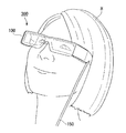
- FIG. 1 is a diagram illustrating a state in which a user wears the HMD of the present embodiment.
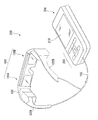
- FIG. 2 is a perspective view of the HMD of this embodiment.
- the HMD 300 of the present embodiment is used by being worn on the head as if the user is wearing glasses.
- the HMD 300 of this embodiment is a see-through type (transmission type) HMD.
- the user can visually recognize an image generated by the image display unit, and can also visually recognize an external image such as a scenery outside the HMD 300.
- the HMD 300 includes a display device 100 having a shape similar to glasses, and a control device (controller) 200 having a size that can be held by a user's hand. .
- the display device 100 and the control device 200 are connected so that they can communicate with each other by wire or wirelessly.
- each of the left-eye image display unit 110A and the right-eye image display unit 110B constituting the display device 100 and the control device 200 are connected to each other via a cable 150 so as to be able to communicate with each other via an image signal. And communicate control signals.
- the display device 100 includes a main frame 120, a left-eye image display unit 110A, and a right-eye image display unit 110B.
- the control device 200 includes a display unit 210 and an operation button unit 250.
- the display unit 210 displays various information and instructions given to the user, for example.
- the main frame 120 includes a pair of temple portions 122A and 122B for a user to put on his ear.
- the main frame 120 is a member that supports the left-eye image display unit 110A and the right-eye image display unit 110B.
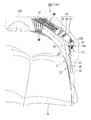
- FIG. 3 is a plan view showing the configuration of each part of the display device 100. Further, FIG. 3 illustrates a state in which the user wearing the display device 100 is viewed from above.
- the right-eye image display unit 110B and the left-eye image display unit 110A have the same configuration, and the components in both the image display units are arranged symmetrically. Therefore, in the following, the right-eye image display unit 110B will be described in detail as simply the image display unit 110, and the description of the left-eye image display unit 110A will be omitted.
- the image display unit 110 includes an image generation unit 11, a pupil enlarging element 12, a first optical system 13, and a second optical system 14.
- the image generation unit 11 emits light including image information.
- the pupil enlarging element 12 expands the beam diameter of light emitted from the optical scanning device 17 described later.
- the image generation unit 11 includes a light source optical system 15, a mirror 16, and an optical scanning device 17.
- the light source optical system 15 emits light generated by an internal semiconductor laser.
- the mirror 16 reflects the light emitted from the light source optical system 15 and turns back the optical path of the light.
- the optical scanning device 17 scans the light reflected by the mirror 16.
- the light source optical system 15 includes a light source unit 25, a pickup lens 26, an optical fiber 27, and a collimator lens 28.
- the light source unit 25 includes a plurality of solid light sources (not shown) including, for example, a semiconductor laser that emits red light, a semiconductor laser that emits green light, and a semiconductor laser that emits blue light. Each color light emitted from each semiconductor laser is modulated in accordance with an image signal, and each modulated color light is synthesized and emitted from the light source unit 25 as image light.
- the pickup lens 26 transmits the light emitted from the light source unit 25 to a subsequent optical fiber 27.
- the optical fiber 27 guides light incident from the light source unit 25 through the pickup lens 26 to the subsequent optical system.
- the collimator lens 28 collimates the light incident from the optical fiber 27.
- the light emitted from the light source optical system 15 is reflected by the mirror 16 so that the optical path is turned back and guided to the optical scanning device 17.
- the optical scanning device 17 includes, for example, a MEMS mirror (not shown).
- the optical scanning device 17 changes the attitude of the MEMS mirror in accordance with the modulation operation of the light source optical system 15 to scan light two-dimensionally. In this way, the optical scanning device 17 emits image light including image information.
- the light emitted from the light source optical system 15 is collimated by the collimator lens 28 to become parallel light.
- the collimated light constitutes image light by changing the angle by the MEMS mirror 18 of the optical scanning device 17.
- the image light whose angle has been converted by the MEMS mirror 18 enters the pupil enlarging element 12.
- the size of the exit pupil is required to be about 6 to 8 mm in consideration of the size of the pupil of the pupil of the eye of the observer H, the movement of the eyeball, and individual differences in eye width.
- the light (image light) from the MEMS mirror 18 is expanded to 6 mm or more by the pupil expansion element 12. Thereby, even if the pupil position of the observer H is slightly deviated, the virtual image G1 can be viewed well, and it is very easy to use.
- the pupil enlarging element 12 has a plurality of parallel flat plates (not shown) and a plurality of half mirrors (not shown). The plurality of parallel flat plates are joined via a half mirror.
- the pupil enlarging element 12 is cut so that a pair of end faces are inclined with respect to the thickness direction of the plane-parallel plate, and the end faces respectively enter a light incident end face 12a and an image on which image light from the optical scanning device 17 is incident.
- a light emitting end face 12b that emits light after being enlarged is configured.
- the horizontal cross-sectional shape of the pupil enlarging element 12 is a trapezoid.
- the image light incident from the light incident end face 12a is repeatedly transmitted and reflected by a plurality of half mirrors, and then emitted from the light exit end face 12b.
- the width of the image light emitted from the light exit end face 12b is enlarged relative to the width of the image light incident on the light incident end face 12a.
- the incident angle of the image light on the light incident end face 12a matches the emission angle of the image light from the light emitting end face 12b.
- image light incident perpendicularly to the light incident end face 12a is emitted perpendicularly from the light exit end face 12b, and image light incident at a predetermined incident angle on the light incident end face 12a is emitted from the light exit end face 12b.
- the light is emitted at an emission angle equal to the incident angle. Accordingly, in FIG. 3, when the image light passes through the pupil enlarging element 12, the optical path is bent toward the shorter side of the trapezoid.
- the first optical system 13 functions as a correction optical system that corrects aberrations and distortion of an image caused by the second optical system 14 when light emitted from the pupil enlarging element 12 enters.
- the first optical system 13 is an optical system including at least positive power and negative power, and has positive power as a whole.
- the first optical system 13 includes a first lens 21, a second lens 22, and a third lens 23 in order from the light incident side.
- the first optical system 13 includes three lenses, ie, the first lens 21, the second lens 22, and the third lens 23, but the number of lenses is not particularly limited.
- the first optical system 13 has a positive power as a whole. Therefore, the light emitted from the pupil enlarging element 12 is collected, and the intermediate image GM is placed in front of the second optical system 14. Can be formed.
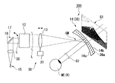
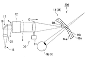
- FIG. 4 is a diagram schematically showing the configuration of the HMD 300 of this embodiment.
- the first optical system 13 is shown as a single lens in order to make the drawing easier to see.
- the second optical system 14 reflects light from the intermediate image GM to guide the virtual image G1 to the eye ME of the observer H and transmits a part of the external light.
- the second optical system 14 for example, a concave mirror with a semi-transparent film deposited thereon, a Fresnel concave mirror, or a reflection hologram formed on an aspherical surface is used.
- a translucent concave mirror (reflective surface) 36a is installed in a lens 36 (transparent plastic) formed by an eye side surface 14a and an external light side surface 14b. It has a structure.
- the visual acuity of the observer using the HMD varies from person to person.
- an observer other than normal vision such as myopia and astigmatism uses the HMD, it is required to adjust diopter for external light and virtual images in order to obtain good image visibility.
- the HMD 300 of the present embodiment can easily perform diopter adjustment for external light and virtual images as will be described later.
- the HMD 300 of this embodiment includes a diopter adjustment means 35 that adjusts the diopter for external light.
- the diopter adjustment means 35 includes a lens 36 formed by the eye side surface 14a and the external light side surface 14b of the second optical system 14.
- the lens 36 constitutes a diopter adjusting means described in the claims that adjusts the diopter for external light by adjusting the shape according to the visual acuity of the observer. to correct.
- the arrangement, refractive index, and shape of the first optical system 13 and the second optical system 14 are determined so that the aberration of the virtual image G1 is reduced.
- the shape of the second optical system 14 (lens 36) is generally a free-form surface, so that aberration can be corrected better.
- the curved surface shape of the external light-side surface 14b is determined so that necessary diopter correction can be performed.
- the diopter adjustment amount of outside light may be set to zero. That is, the shape of the eye-side surface 14a and the external light-side surface 14b is adjusted so as not to have refractive power with respect to external light. That is, the average curvature radius of the eye-side surface 14a is set to be slightly larger than the average curvature radius of the external light-side surface 14b.
- the lens 36 having negative power as a whole is used by setting the average radius of curvature of the external light side surface 14b to be larger than the average radius of curvature of the eye side surface 14a. That's fine.
- the lens 36 having positive power as a whole is used.
- the lens 36 can be a bifocal lens as a progressive focus lens. Diopter adjustment of external light is possible independently of the diopter and position of a virtual image G1, which will be described later.
- the lens 36 (second optical system 14) is detachable from the main frame 120 (see FIG. 3). Therefore, by exchanging the lens 36 according to the visual acuity, the observer H having various visual acuities can visually recognize the external light satisfactorily.
- the HMD 300 of the present embodiment includes intermediate image position changing means 30 that adjusts the position in the depth direction of the virtual image G1 by changing the position of the intermediate image GM to adjust the diopter for the virtual image G1.
- the intermediate image position changing unit 30 includes a moving device 31 that moves the first optical system 13 in the direction of the central ray of the light (image light L) emitted from the pupil enlarging element 12.
- the first optical system 13 can be moved by using a screw or an eccentric pin along a guide, or the first optical system can be automatically used by using a motor, an actuator, or the like. The thing which moves the system
- strain 13 can be illustrated.
- the first optical system 13 is composed of a plurality of lenses (first lens 21, second lens 22, and third lens 23).
- the intermediate image position changing unit 30 may move the entire first optical system 13 (three lenses), or may move only one of the three lenses.
- the diopter adjustment function for the virtual image G1 will be described.
- the diopter adjustment of the virtual image is performed according to the diopter adjustment of the external light by the diopter adjustment means 35. That is, when adjusting the position of the virtual image corresponding to the myopic observer H, the myopia lens 36 corresponding to the myopic observer H may be used.
- FIG. 5 is a diagram for explaining a case where diopter adjustment is performed for a nearsighted observer H.
- FIG. 4 shows only the light beam at the center of the image (virtual image G1).
- the moving device 31 moves the first optical system 13 so as to approach the second optical system 14 side.
- the position of the intermediate image GM approaches the second optical system 14.
- the divergent light L1 forms an image on the retina of the myopic observer H.
- the first optical system 13 may be moved closer to the second optical system 14 by the moving device 31.
- diopter adjustment is performed for a hyperopic observer H.
- the diopter adjustment of the virtual image is performed according to the diopter adjustment of the external light by the diopter adjustment means 35.
- the above-mentioned lens 36 for hyperopia corresponding to the hyperopic observer H may be used.
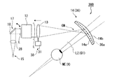
- FIG. 6 is a diagram for explaining a case where diopter adjustment is performed for a hyperopic observer H.
- FIG. 6 shows only the light beam at the center of the image (virtual image G1).
- the moving device 31 moves the first optical system 13 so as to be away from the second optical system 14.
- the position of the intermediate image GM is separated from the second optical system 14.
- the light from the intermediate image GM reflected by the second optical system 14 becomes the convergent light L2.
- the convergent light L2 forms an image on the retina of the far-sighted observer H.
- the intermediate image position changing means 30 may be used to adjust the position of the virtual image G1 in the depth direction with respect to the observer H with normal vision.
- the intermediate image GM may be brought closer to the second optical system 14 as shown in FIG.
- the intermediate image GM may be moved away from the second optical system 14 as shown in FIG.
- the position of the virtual image G1 in the depth direction can be adjusted with a simple configuration in which the intermediate image position changing unit 30 changes the position of the intermediate image GM. Adjustment). Moreover, since the diopter adjustment means 35 is provided, diopter adjustment with respect to external light can be performed. Therefore, since the diopter for the external light and the virtual image is adjusted with a good balance, the HMD 300 having excellent visibility is provided.
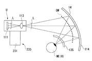
- FIG. 7 is a diagram showing a schematic configuration in the HMD 301 of the present embodiment.
- FIG. 7 shows only the central rays of the center of the image (virtual image) and the angle of view at both ends.
- the HMD 301 of this embodiment includes an image generation unit 111, a lens (first condensing optical system) 113, a second optical system 114, an intermediate image position changing unit 230, and a diopter adjustment unit 135. Have.
- the image generation unit 111 includes a display panel (electro-optical device) 112.
- the display panel 112 includes a backlight (not shown) and a light modulation element (not shown).
- the backlight is composed of a set of light sources for each emission color such as red, green and blue.
- each light source for example, a light emitting diode (LED) or a laser light source can be used.
- As the light modulation element for example, a liquid crystal display device which is a display element can be used.
- an organic electroluminescence device organic EL device or the like can also be employed.
- the lens 113 has positive power, collects light emitted from the display panel 112, and forms an intermediate image GM in front of the second optical system 114.
- the second optical system 114 includes a concave mirror that reflects light from the intermediate image GM to guide the virtual image G1 to the eyes of the observer H and transmits part of the external light.
- the image generation unit 111 and the lens 113 are integrated to form an image unit U.
- the intermediate image position changing unit 230 includes a moving device 231 that moves the image unit U in the direction of the central ray of the light (image light L) emitted from the image unit U (left-right direction in FIG. 7).
- the lens 113 may be comprised from the some lens similarly to 1st Embodiment.
- the image unit U only needs to include at least one of a plurality of lenses, and the intermediate image position changing unit 230 moves only the lens included in the image unit U (a part of the lens 113). You may do it.
- the diopter adjusting means 135 is composed of a spectacle lens (inner lens).
- the diopter adjustment means 135 is supported by a support member (not shown) provided on the main frame 120, is a position that avoids the optical path of image light from the lens 113 to the second optical system 114, and It is detachably disposed between the second optical system 114 and the eyes of the observer H.
- the external light visibility in the observer H of various visual acuity can be improved by replacing
- the position of the intermediate image GM is changed by moving the image unit U in the optical axis direction of the image light, and the visual image G1 is viewed together with the diopter adjustment means 135 (glasses lens).
- the degree adjustment and the position adjustment of the virtual image G1 can be easily and reliably performed.
- the position of the virtual image G1 in the depth direction (virtual image diopter adjustment) can be adjusted with a simple configuration in which the position of the intermediate image GM is changed by the intermediate image position changing unit 230. it can.
- the diopter adjustment unit 135 is provided, diopter adjustment with respect to external light can be performed. Therefore, since the diopter for the external light and the virtual image is adjusted with a good balance, the HMD 300 having excellent visibility is provided.
- the HMDs 300 and 301 including the intermediate image position changing units 30 and 120 and the diopter adjustment units 35 and 135 have been described as examples, but the present invention is not limited thereto.
- the HMD of the present invention only needs to include at least the intermediate image position changing means 30 and 120. According to this, the position of the virtual image G1 in the depth direction can be changed with a simple configuration such as changing the position of the intermediate image GM. Can be adjusted.
- the position of the intermediate image GM is changed by moving the first optical system 13 and the lens 113 to adjust the position of the virtual image G1 in the depth direction is described as an example.
- the invention is not limited to this, and the position of the intermediate image GM may be changed by moving the second optical systems 14 and 114.
- the optimal position in the depth direction of the virtual image changes depending on whether you are looking at a distant view (external light) or a close view (external light). That is, if the position of the virtual image in the depth direction is deviated from the optimum position, the viewer feels uncomfortable when viewing the external light and the virtual image at the same time.
- the intermediate image position changing means 30 and 230 may adjust the position of the virtual image G1 in the depth direction according to the external light visually recognized by the observer H, for example.
- a detection unit for example, a CCD camera
- the intermediate image position changing units 30 and 230 are controlled based on the detection result of the detection unit.
- the position of the image GM may be changed. In this way, the position of the virtual image in the depth direction can be optimized when viewing a distant view (external light) and when viewing a close view (external light).
- the position of the virtual image in the depth direction is optimal as the line of sight moves, even if the line of sight moves from a distant view to a close view. Therefore, it is possible to obtain a good image visibility without causing a sense of incongruity.
- H observer, ME ... eye, G1 ... virtual image, L ... image light, MG ... intermediate image, 11, 111 ... image generation unit, 12 ... pupil magnifying element (magnifying element), 13 ... first optical system, 14 , 114 ... second optical system, 17 ... optical scanning device, 30, 230 ... intermediate image position changing means, 35, 135 ... movement adjusting means, 36 ... lens, 112 ... display panel (electro-optical device), 300, 301 ... HMD (image display device).
Abstract
虚像に対する視度を簡便に調整できる、画像表示装置を提供する。 本発明の画像表示装置は、画像情報を含む画像光を射出する画像生成部と、画像光を集光して中間像を形成する第1の光学系と、中間像からの光を偏向して虚像を観察者の眼に導くとともに、外光を透過させることで観察者の眼に導く第2の光学系と、中間像の位置を変更することで虚像の奥行方向の位置を調整する中間像位置変更手段と、を備えることを特徴とする。
Description
本発明は、画像表示装置に関するものである。
近年、ヘッドマウントディスプレイ等の装着型の画像表示装置が注目されている。このようなヘッドマウントディスプレイとして、表示素子からの映像(虚像)に加えて外界の像(外光)を同時に視認できる、シースルー方式のものが知られている(例えば、特許文献1参照)。
このシースルー方式の画像表示装置では、近視や遠視等の装着者であっても、外光の視度調整を行うことで外光の視認性を高めている。
近視や遠視等の装着者がシースルー方式の画像表示装置を利用する場合、虚像に対する視度調整(虚像の奥行方向の位置の調整)も必要となる。しかしながら、上記従来技術では、虚像に対する視度調整が考慮されていなかった。そこで、虚像に対する視度調整を簡便に行うことが可能な新たな技術の提供が望まれていた。
本発明はこのような事情に鑑みてなされたものであって、虚像に対する視度を簡便に調整できる、画像表示装置を提供することを目的とする。
本発明の第1態様に従えば、画像情報を含む画像光を射出する画像生成部と、前記画像光を集光して中間像を形成する第1の光学系と、前記中間像からの光を偏向して虚像を観察者の眼に導くとともに、外光を透過させることで前記観察者の眼に導く第2の光学系と、前記中間像の位置を変更することで前記虚像の奥行方向の位置を調整する中間像位置変更手段と、を備える画像表示装置が提供される。
第1態様に係る画像表示装置によれば、中間像の位置を変更するといった簡便な構成により、虚像に対する視度調整を行うことができる。
上記第1態様において、前記画像生成部は、光源部から射出された光を走査する光走査デバイスと、前記光走査デバイスからの光を拡大して前記画像光として射出する拡大素子と、を含み、中間像位置変更手段は、前記第1の光学系の少なくとも一部を前記画像光の中心光線の方向に移動させる構成としてもよい。
この構成によれば、画像生成部が小型化される。また、中間像位置変更手段は、第1の光学系の少なくとも一部を移動させるので、装置構成が単純化されて小型なものとなる。よって、装置全体を小型化できる。
この構成によれば、画像生成部が小型化される。また、中間像位置変更手段は、第1の光学系の少なくとも一部を移動させるので、装置構成が単純化されて小型なものとなる。よって、装置全体を小型化できる。
上記第1態様において、前記画像生成部は、前記画像光を生成する電気光学装置を含み、中間像位置変更手段は、前記第1の光学系の少なくとも一部を前記画像光の中心光線の方向に移動させる構成としてもよい。
この構成によれば、中間像位置変更手段が第1の光学系の少なくとも一部を移動させるので、装置構成が単純化されて小型なものとなる。よって、装置全体を小型化できる。
この構成によれば、中間像位置変更手段が第1の光学系の少なくとも一部を移動させるので、装置構成が単純化されて小型なものとなる。よって、装置全体を小型化できる。
本発明の第2態様に従えば、画像情報を含む画像光を射出する画像生成部と、前記画像光を集光して中間像を形成する第1の光学系と、前記中間像からの光を偏向して虚像を観察者の眼に導くとともに、外光を透過させることで前記観察者の眼に導く第2の光学系と、前記外光に対する視度を調整する視度調整手段と、前記中間像の位置を変更することで前記虚像の奥行方向の位置を調整する中間像位置変更手段と、を備える画像表示装置が提供される。
第21態様に係る画像表示装置によれば、中間像の位置を変更するといった簡便な構成により、虚像の奥行方向の位置の調整(虚像の視度調整)を行うことができる。さらに、外光に対する視度調整も行うことができる。
上記第2態様において、前記中間像位置変更手段は、前記画像生成部と前記第1の光学系の少なくとも一部とを一体で前記画像光の中心光線の方向に移動させる構成としてもよい。
この構成によれば、中間像の位置を簡便且つ確実に変更することができる。
この構成によれば、中間像の位置を簡便且つ確実に変更することができる。
上記第2態様において、前記中間像位置変更手段は、前記第1の光学系の少なくとも一部を前記画像光の中心光線の方向に移動させる構成としてもよい。
この構成によれば、中間像位置変更手段が第1の光学系の少なくとも一部を移動させるので、装置構成が単純化されて小型なものとなる。よって、装置全体を小型化できる。
この構成によれば、中間像位置変更手段が第1の光学系の少なくとも一部を移動させるので、装置構成が単純化されて小型なものとなる。よって、装置全体を小型化できる。
上記第2態様において、前記視度調整手段は、前記第2の光学系の外光側表面と前記観察者の眼側表面とで形成するレンズから構成される構成としてもよい。
この構成によれば、視度調整手段と第2の光学系とを兼用することができる。よって、部品点数を削減することができ、装置の小型化を実現できる。
この構成によれば、視度調整手段と第2の光学系とを兼用することができる。よって、部品点数を削減することができ、装置の小型化を実現できる。
上記第2態様において、前記視度調整手段は、前記第2の光学系と前記観察者の眼の間に配置された眼鏡レンズから構成される構成としてもよい。
この構成によれば、眼鏡レンズを用いるので、小型且つ簡便に外光の視度調整を行うことができる。
この構成によれば、眼鏡レンズを用いるので、小型且つ簡便に外光の視度調整を行うことができる。
上記第2態様において、前記中間像位置変更手段は、前記視度調整手段による前記外光の視度調整に応じて、前記虚像の奥行方向の位置を調整する構成としてもよい。
この構成によれば、外光および虚像に対する視度がバランス良く調整されるので、視認性に優れた画像表示装置を提供できる。
この構成によれば、外光および虚像に対する視度がバランス良く調整されるので、視認性に優れた画像表示装置を提供できる。
以下、本発明の実施の形態について、図面を参照して詳細に説明する。
なお、以下の説明で用いる図面は、特徴をわかりやすくするために、便宜上特徴となる部分を拡大して示している場合があり、各構成要素の寸法比率などが実際と同じであるとは限らない。
なお、以下の説明で用いる図面は、特徴をわかりやすくするために、便宜上特徴となる部分を拡大して示している場合があり、各構成要素の寸法比率などが実際と同じであるとは限らない。
以下、本発明の一実施形態について、図面を参照しつつ説明する。
本実施形態の画像表示装置は、使用者が頭に装着して使用するヘッドマウントディスプレイの一例である。
以下の説明では、ヘッドマウントディスプレイ(Head Mounted Display)を、HMDと略記する。
図1は、使用者が本実施形態のHMDを装着した状態を示す図である。
図2は、本実施形態のHMDの斜視図である。
本実施形態の画像表示装置は、使用者が頭に装着して使用するヘッドマウントディスプレイの一例である。
以下の説明では、ヘッドマウントディスプレイ(Head Mounted Display)を、HMDと略記する。
図1は、使用者が本実施形態のHMDを装着した状態を示す図である。
図2は、本実施形態のHMDの斜視図である。
図1に示すように、本実施形態のHMD300は、使用者が眼鏡を掛ける感覚で頭部に装着して使用するものである。本実施形態のHMD300は、シースルー型(透過型)のHMDである。本実施形態のHMD300によれば、使用者は画像表示部により生成された画像を視認でき、かつ、HMD300の外部の景色等の外界の像も視認できる。
図2に示すように、HMD300は、眼鏡に類似した形状を有する表示装置100と、使用者が手で持つことが可能な程度の大きさを有する制御装置(コントローラー)200と、を備えている。表示装置100と制御装置200とは、有線または無線で通信可能に接続される。本実施形態では、表示装置100を構成する左眼用画像表示部110Aおよび右眼用画像表示部110Bの各々と制御装置200とは、ケーブル150を介して有線で通信可能に接続され、画像信号や制御信号を通信する。
表示装置100は、メインフレーム120と、左眼用画像表示部110Aと、右眼用画像表示部110Bと、を備えている。制御装置200は、表示部210と、操作ボタン部250と、を備えている。表示部210は、例えば使用者に与える各種の情報や指示等を表示する。メインフレーム120は、使用者が耳に掛けるための一対のテンプル部122A,122Bを備えている。メインフレーム120は、左眼用画像表示部110Aと、右眼用画像表示部110Bと、を支持する部材である。
図3は、表示装置100の各部の構成を示す平面図である。さらに、図3では、表示装置100を装着する使用者を頭上から見た状態を図示している。
右眼用画像表示部110Bと左眼用画像表示部110Aとは、同様の構成を有しており、双方の画像表示部内の各構成要素は左右対称に配置されている。そのため、以下では、右眼用画像表示部110Bを単に画像表示部110として詳細に説明し、左眼用画像表示部110Aの説明を省略する。
右眼用画像表示部110Bと左眼用画像表示部110Aとは、同様の構成を有しており、双方の画像表示部内の各構成要素は左右対称に配置されている。そのため、以下では、右眼用画像表示部110Bを単に画像表示部110として詳細に説明し、左眼用画像表示部110Aの説明を省略する。
図3に示すように、画像表示部110は、画像生成部11と、瞳拡大素子12と、第1の光学系13と、第2の光学系14と、を備えている。画像生成部11は、画像情報を含む光を射出する。瞳拡大素子12は、後述する光走査デバイス17から射出された光のビーム径を拡大する。
画像生成部11は、光源光学系15と、ミラー16と、光走査デバイス17と、を備えている。光源光学系15は、内部の半導体レーザーで生成された光を射出する。ミラー16は、光源光学系15から射出された光を反射し、光の光路を折り返す。光走査デバイス17は、ミラー16で反射した光を走査する。
光源光学系15は、光源部25と、ピックアップレンズ26と、光ファイバー27と、コリメーターレンズ28と、を備えている。光源部25は、例えば赤色光を射出する半導体レーザー、緑色光を射出する半導体レーザー、および青色光を射出する半導体レーザーを含む複数の固体光源(図示略)を備えている。各半導体レーザーから射出される各色光は、画像信号に応じて変調され、変調された各色光が合成され、画像光として光源部25から射出される。ピックアップレンズ26は、光源部25から射出した光を後段の光ファイバー27に伝達する。光ファイバー27は、光源部25からピックアップレンズ26を経て入射した光を後段の光学系に導く。コリメーターレンズ28は、光ファイバー27から入射した光を平行化する。
光源光学系15から射出された光は、ミラー16で反射することで光路が折り返され、光走査デバイス17に導かれる。光走査デバイス17は、例えばMEMSミラー(図示略)を備えている。光走査デバイス17は、光源光学系15の変調動作に合わせてMEMSミラーの姿勢を変化させ、光を2次元的に走査する。このようにして、光走査デバイス17は、画像情報を含む画像光を射出する。
光源光学系15から射出された光は、コリメーターレンズ28により平行化されて平行光となる。平行化された光は、光走査デバイス17のMEMSミラー18により角度が変換されたことで画像光を構成する。MEMSミラー18により角度が変換された画像光は、瞳拡大素子12に入射する。
一般に、観察者Hの眼の瞳の瞳孔の大きさや、眼球の動き、眼幅の個人差などを考慮すると射出瞳の大きさは6~8mm程度必要と考えられる。本実施形態のHMD300では、MEMSミラー18からの光(画像光)を瞳拡大素子12により6mm以上まで拡大している。これにより、観察者Hの瞳位置が多少ずれたとしても虚像G1を良好に視認することが可能であり、非常に使い勝手に優れたものとしている。
瞳拡大素子12は、複数の平行平面板(不図示)と、複数のハーフミラー(不図示)と、を有している。複数の平行平面板は、ハーフミラーを介して接合されている。瞳拡大素子12は、一対の端面が平行平面板の厚さ方向に対して傾斜するようにカットされており、該端面がそれぞれ光走査デバイス17からの画像光を入射させる光入射端面12aおよび画像光を拡大して射出される光射出端面12bを構成する。このように、瞳拡大素子12の水平断面形状は台形となっている。
瞳拡大素子12においては、光入射端面12aから入射した画像光が複数のハーフミラーで透過および反射を繰り返した後、光射出端面12bから射出される。光射出端面12bから射出された画像光の幅は、光入射端面12aに入射した画像光の幅に対して拡大される。また、光入射端面12aへの画像光の入射角度と光射出端面12bからの画像光の射出角度とは一致する。
したがって、例えば光入射端面12aに対して垂直に入射した画像光は光射出端面12bから垂直に射出され、光入射端面12aに対して所定の入射角度で入射した画像光は、光射出端面12bから入射角度と等しい射出角度で射出される。これにより、図3においては、画像光が瞳拡大素子12を透過する際、光路は台形の短辺側に曲がっている。
第1の光学系13は、瞳拡大素子12から射出された光が入射され、第2の光学系14に起因して生じる像の収差や歪曲を補正する補正光学系として機能する。第1の光学系13は、少なくとも正のパワーと負のパワーとを含む光学系であり、全体として正のパワーを有する。本実施形態において、第1の光学系13は、光入射側から順に、第1レンズ21と、第2レンズ22と、第3レンズ23と、を有している。なお、本実施形態では、第1の光学系13は、第1レンズ21、第2レンズ22および第3レンズ23の3枚のレンズで構成されているが、レンズの枚数は特に限定されない。
このような構成に基づき、第1の光学系13は全体として正のパワーを有するため、瞳拡大素子12から射出された光を集光して、第2の光学系14の手前に中間像GMを形成することが可能である。
図4は本実施形態のHMD300の構成を模式化した図である。なお、図4において、第1の光学系13は図を見易くするため、1枚のレンズとして図示している。
図4に示すように、第2の光学系14は、中間像GMからの光を反射して虚像G1を観察者Hの眼MEに導くとともに、外光の一部を透過させる。第2の光学系14としては、例えば、半透明膜を蒸着した凹面鏡、フレネル凹面鏡、非球面に反射型ホログラムを形成したもの等が用いられる。本実施形態の第2の光学系14は、例えば、眼側表面14aと外光側表面14bとで形成されるレンズ36(透明プラスチック)中に半透明の凹面鏡(反射面)36aが設置された構造を有する。
図4に示すように、第2の光学系14は、中間像GMからの光を反射して虚像G1を観察者Hの眼MEに導くとともに、外光の一部を透過させる。第2の光学系14としては、例えば、半透明膜を蒸着した凹面鏡、フレネル凹面鏡、非球面に反射型ホログラムを形成したもの等が用いられる。本実施形態の第2の光学系14は、例えば、眼側表面14aと外光側表面14bとで形成されるレンズ36(透明プラスチック)中に半透明の凹面鏡(反射面)36aが設置された構造を有する。
ところで、HMDを利用する観察者の視力は人によって様々である。例えば、近視や乱視等の通常視力以外の観察者がHMDを使用する場合において、良好な画像視認性を得るべく、外光および虚像に対する視度調整を行うことが要求される。
本実施形態のHMD300は、後述のように外光および虚像に対する視度調整を簡便に行うことが可能となっている。
本実施形態のHMD300は、後述のように外光および虚像に対する視度調整を簡便に行うことが可能となっている。
本実施形態のHMD300は、外光に対する視度を調整する視度調整手段35を備えている。視度調整手段35は、第2の光学系14の眼側表面14aと外光側表面14bとで形成するレンズ36によって構成されている。レンズ36は、観察者の視力に応じて形状を調整する事により、外光に対して視度を調整する特許請求の範囲に記載の視度調整手段を構成する。補正する。
以下、レンズ36の形状決定方法について説明する。
まず、虚像G1の収差が少なくなるように第1の光学系13および第2の光学系14の配置、屈折率、形状を決定する。この時、第2の光学系14(レンズ36)の形状は、一般に自由曲面とする事により、より良く収差を補正できる。眼側表面14aおよび凹面鏡37の各曲面の形状を決定したのち、必要な視度補正ができるように外光側表面14bの曲面形状を決定する。
まず、虚像G1の収差が少なくなるように第1の光学系13および第2の光学系14の配置、屈折率、形状を決定する。この時、第2の光学系14(レンズ36)の形状は、一般に自由曲面とする事により、より良く収差を補正できる。眼側表面14aおよび凹面鏡37の各曲面の形状を決定したのち、必要な視度補正ができるように外光側表面14bの曲面形状を決定する。
例えば、通常視力の観察者Hに対しては、外光の視度調整量を0とすればよい。すなわち、眼側表面14aおよび外光側表面14bの形状を調整して外光に対して屈折力を持たないようにする。すなわち、外光側表面14bの平均的な曲率半径よりも眼側表面14aの平均的な曲率半径をわずかに大きな値とする。
また、近視の観察者Hに対しては、外光側表面14bの平均的な曲率半径を眼側表面14aの平均的な曲率半径よりさらに大きな値として全体として負のパワーを有するレンズ36を用いればよい。
また、遠視の観察者Hに対しては、外光側表面14bの平均的な曲率半径を眼側表面14aの平均的な曲率半径より小さくして全体として正のパワーを有するレンズ36を用いればよい。なお、レンズ36としては、累進焦点レンズとして遠近両用レンズとする事も可能である。外光の視度調整は、後述する虚像G1の視度や位置とは独立に可能である。
また、レンズ36(第2の光学系14)は、メインフレーム120(図3参照)に対して着脱可能とされている。そのため、視力に応じたレンズ36に交換することで、様々な視力の観察者Hが外光を良好に視認することが可能となっている。
また、本実施形態のHMD300は、中間像GMの位置を変更することで虚像G1の奥行方向の位置を調整して虚像G1に対する視度を調整する中間像位置変更手段30を備えている。中間像位置変更手段30は、第1の光学系13を瞳拡大素子12から射出される光(画像光L)の中心光線の方向に移動する移動装置31を備えている。
移動装置31としては、例えば、ガイドに沿ってネジや偏芯ピンを使用することで第1の光学系13を移動させるものや、モーターやアクチュエーター等を使用することで自動的に第1の光学系13を移動させるものを例示できる。
本実施形態では、第1の光学系13が複数のレンズ(第1レンズ21、第2レンズ22および第3レンズ23)から構成されている。中間像位置変更手段30は、第1の光学系13の全体(3つのレンズ)を移動しても良いし、3枚のレンズのうち、いずれか1枚だけを移動させるようにしてもよい。
以下、虚像G1に対する視度調整機能について説明する。
まず、近視の観察者Hに対して虚像の視度調整を行う場合について説明する。なお、視度調整手段35による外光の視度調整に応じて、虚像の視度調整を行うようにしている。すなわち、近視の観察者Hに対応して虚像の位置調整を行う場合、近視の観察者Hに対応した近視用の上記レンズ36を用いればよい。
まず、近視の観察者Hに対して虚像の視度調整を行う場合について説明する。なお、視度調整手段35による外光の視度調整に応じて、虚像の視度調整を行うようにしている。すなわち、近視の観察者Hに対応して虚像の位置調整を行う場合、近視の観察者Hに対応した近視用の上記レンズ36を用いればよい。
図5は近視の観察者Hに対して視度調整を行う場合を説明する図である。なお、図4には画像(虚像G1)の中央の光束のみを図示している。
図5に示すように、移動装置31は、第1の光学系13を第2の光学系14側に近づけるように移動させる。これにより、中間像GMの位置が第2の光学系14に近づく。これにより、第2の光学系14で反射された中間像GMからの光は、発散光となる。発散光L1は、近視の観察者Hの網膜上で結像する。なお、虚像G1の位置をより手前に近づけたい場合、移動装置31により第1の光学系13を第2の光学系14にさらに近づけるように移動させれば良い。
続いて、遠視の観察者Hに対して視度調整を行う場合について説明する。なお、視度調整手段35による外光の視度調整に応じて、虚像の視度調整を行うようにしている。すなわち、遠視の観察者Hに対応して虚像の位置調整を行う場合、遠視の観察者Hに対応した遠視用の上記レンズ36を用いればよい。
図6は遠視の観察者Hに対して視度調整を行う場合を説明する図である。なお、図6には画像(虚像G1)の中央の光束のみを図示している。
図6に示すように、移動装置31は、第1の光学系13を第2の光学系14から遠ざけるように移動させる。これにより、中間像GMの位置が第2の光学系14から離れる。これにより、第2の光学系14で反射された中間像GMからの光は収束光L2となる。収束光L2は、遠視の観察者Hの網膜上で結像する。
なお、中間像位置変更手段30を用いて、通常視力の観察者Hに対して虚像G1の奥行方向の位置を調整するようにしてもよい。この場合において、例えば、虚像G1の位置を奥行方向手前に近づける際には、図5に示したように、中間像GMを第2の光学系14に近づけるようにすればよい。あるいは、虚像G1の位置を奥行方向に遠ざけるには、図6に示したように、中間像GMを第2の光学系14から遠ざけるようにすればよい。
以上述べたように、本実施形態のHMD300によれば、中間像位置変更手段30により中間像GMの位置を変更するといった簡便な構成により、虚像G1の奥行方向の位置の調整(虚像の視度調整)を行うことができる。また、視度調整手段35を備えるので、外光に対する視度調整を行うことができる。よって、外光および虚像に対する視度がバランス良く調整されるので、視認性に優れたHMD300が提供される。
(第2実施形態)
続いて、本発明の第2実施形態について説明する。本実施形態と第1実施形態との違いは画像生成部および中間像位置変更手段の構造であり、それ以外の構成は共通であるため、共通の構成については同じ符号を付し、その詳細な説明については省略する。
続いて、本発明の第2実施形態について説明する。本実施形態と第1実施形態との違いは画像生成部および中間像位置変更手段の構造であり、それ以外の構成は共通であるため、共通の構成については同じ符号を付し、その詳細な説明については省略する。
図7は、本実施形態のHMD301における概略構成を示す図である。なお、図7には画像(虚像)の中央と両端の画角の中心光線のみを図示している。
本実施形態のHMD301は、画像生成部111と、レンズ(第1の集光光学系)113と、第2の光学系114と、中間像位置変更手段230と、視度調整手段135と、を有している。
本実施形態のHMD301は、画像生成部111と、レンズ(第1の集光光学系)113と、第2の光学系114と、中間像位置変更手段230と、視度調整手段135と、を有している。
本実施形態の画像生成部111は、表示パネル(電気光学装置)112から構成される。
表示パネル112は、バックライト(不図示)と光変調素子(不図示)とを含む。バックライトは、例えば赤色、緑色および青色といった発光色ごとの光源の集合から構成されている。各光源としては、例えば、発光ダイオード(LED:Light Emitting Diode)やレーザー光源などを用いることができる。光変調素子としては、例えば、表示素子である液晶表示デバイスなどを用いることができる。なお、表示パネル112としては、他にも、有機エレクトロルミネッセンス装置(有機EL装置)等を採用することもできる。
表示パネル112は、バックライト(不図示)と光変調素子(不図示)とを含む。バックライトは、例えば赤色、緑色および青色といった発光色ごとの光源の集合から構成されている。各光源としては、例えば、発光ダイオード(LED:Light Emitting Diode)やレーザー光源などを用いることができる。光変調素子としては、例えば、表示素子である液晶表示デバイスなどを用いることができる。なお、表示パネル112としては、他にも、有機エレクトロルミネッセンス装置(有機EL装置)等を採用することもできる。
レンズ113は正のパワーを有し、表示パネル112から射出された光を集光して、第2の光学系114の手前に中間像GMを形成する。第2の光学系114は、中間像GMからの光を反射して虚像G1を観察者Hの眼に導くとともに、外光の一部を透過させる凹面鏡から構成されている。本実施形態において、画像生成部111およびレンズ113は一体化されることで画像ユニットUを構成している。
中間像位置変更手段230は、画像ユニットUから射出される光(画像光L)の中心光線の方向(図7中の左右方向)に該画像ユニットUを移動させる移動装置231を備えている。
なお、レンズ113が第1実施形態と同様、複数のレンズから構成されていてもよい。この場合において、画像ユニットUは、複数のレンズのうちの少なくとも1枚を含んでいればよく、中間像位置変更手段230は画像ユニットUに含まれるレンズのみ(レンズ113の一部)を移動させるようにしてもよい。
本実施形態のHMD301では、視度調整手段135により外光に対する視度調整を行う。視度調整手段135は眼鏡レンズ(インナーレンズ)から構成されている。視度調整手段135は、メインフレーム120に設けられた不図示の支持部材に支持されることで、レンズ113から第2の光学系114への画像光の光路を避けた位置であり、且つ、第2の光学系114と観察者Hの眼の間に着脱可能に配置されている。なお、観察者Hの視力に対応した視度調整手段135(眼鏡レンズ)に交換することで、種々な視力の観察者Hにおける外光視認性を高めることができる。
また、本実施形態のHMD301では、画像ユニットUを画像光の光軸方向に移動させることにより中間像GMの位置を変化させて、視度調整手段135(眼鏡レンズ)と合わせて虚像G1の視度調整および虚像G1の位置調整を簡便且つ確実に行うことができる。
本実施形態のHMD301によれば、中間像位置変更手段230により中間像GMの位置を変更するといった簡便な構成により、虚像G1の奥行方向の位置の調整(虚像の視度調整)を行うことができる。また、視度調整手段135を備えるので、外光に対する視度調整を行うことができる。よって、外光および虚像に対する視度がバランス良く調整されるので、視認性に優れたHMD300が提供される。
なお、本発明の技術範囲は上記実施形態に限定されるものではなく、本発明の趣旨を逸脱しない範囲において種々の変更を加えることが可能である。
例えば、上記実施形態では、中間像位置変更手段30,120および視度調整手段35,135をそれぞれ備えたHMD300,301を例に挙げて説明したが、本発明はこれに限定されない。本発明のHMDは、少なくとも中間像位置変更手段30,120のみを備えていればよく、これによれば、中間像GMの位置を変更するといった簡便な構成により、虚像G1の奥行方向の位置の調整することができる。
例えば、上記実施形態では、中間像位置変更手段30,120および視度調整手段35,135をそれぞれ備えたHMD300,301を例に挙げて説明したが、本発明はこれに限定されない。本発明のHMDは、少なくとも中間像位置変更手段30,120のみを備えていればよく、これによれば、中間像GMの位置を変更するといった簡便な構成により、虚像G1の奥行方向の位置の調整することができる。
また、上記実施形態では、第1の光学系13およびレンズ113を移動させることで中間像GMの位置を変更して、虚像G1の奥行方向の位置を調整する場合を例に挙げたが、本発明はこれに限定されず、第2の光学系14および114を移動させることで中間像GMの位置を変更するようにしてもよい。
ところで、遠くの景色(外光)を見ている場合と近くの景色(外光)を見ている場合とで、虚像の奥行方向における最適位置が変化する。すなわち、虚像の奥行方向の位置が最適位置からずれると、外光と虚像とを同時に視認する際に観察者には違和感が生じてしまう。
これに対し、中間像位置変更手段30、230は、例えば、観察者Hが視認している外光に応じて、虚像G1の奥行方向の位置を調整するようにしてもよい。
この場合、観察者Hが視認している外光を検出する検出手段(例えば、CCDカメラ等)を用い、該検出手段の検出結果に基づいて中間像位置変更手段30、230を制御して中間像GMの位置を変更するようにすればよい。
このようにすれば、遠くの景色(外光)を見ている場合と近くの景色(外光)を見ている場合とで、虚像の奥行方向における位置を最適化することができる。よって、観察者は、外光(景色)と虚像とを同時に視認する際、遠くの景色から近くの景色に視線を移動した場合でも、該視線の移動に伴って虚像の奥行方向の位置が最適な位置に調整されるので、違和感を生じることなく、良好な画像視認性を得ることができる。
この場合、観察者Hが視認している外光を検出する検出手段(例えば、CCDカメラ等)を用い、該検出手段の検出結果に基づいて中間像位置変更手段30、230を制御して中間像GMの位置を変更するようにすればよい。
このようにすれば、遠くの景色(外光)を見ている場合と近くの景色(外光)を見ている場合とで、虚像の奥行方向における位置を最適化することができる。よって、観察者は、外光(景色)と虚像とを同時に視認する際、遠くの景色から近くの景色に視線を移動した場合でも、該視線の移動に伴って虚像の奥行方向の位置が最適な位置に調整されるので、違和感を生じることなく、良好な画像視認性を得ることができる。
H…観察者、ME…眼、G1…虚像、L…画像光、MG…中間像、11,111…画像生成部、12…瞳拡大素子(拡大素子)、13…第1の光学系、14,114…第2の光学系、17…光走査デバイス、30,230…中間像位置変更手段、35,135…移動調整手段、36…レンズ、112…表示パネル(電気光学装置)、300,301…HMD(画像表示装置)。
Claims (11)
- 画像情報を含む画像光を射出する画像生成部と、
前記画像光を集光して中間像を形成する第1の光学系と、
前記中間像からの光を偏向して虚像を観察者の眼に導くとともに、外光を透過させることで前記観察者の眼に導く第2の光学系と、
前記中間像の位置を変更することで前記虚像の奥行方向の位置を調整する中間像位置変更手段と、を備える
ことを特徴とする画像表示装置。 - 前記画像生成部は、光源部から射出された光を走査する光走査デバイスと、前記光走査デバイスからの光を拡大して前記画像光として射出する拡大素子と、を含み、
中間像位置変更手段は、前記第1の光学系の少なくとも一部を前記画像光の中心光線の方向に移動させる
ことを特徴とする請求項1に記載の画像表示装置。 - 前記画像生成部は、前記画像光を生成する電気光学装置を含み、
中間像位置変更手段は、前記第1の光学系の少なくとも一部を前記画像光の中心光線の方向に移動させる
ことを特徴とする請求項1に記載の画像表示装置。 - 画像情報を含む画像光を射出する画像生成部と、
前記画像光を集光して中間像を形成する第1の光学系と、
前記中間像からの光を偏向して虚像を観察者の眼に導くとともに、外光を透過させることで前記観察者の眼に導く第2の光学系と、
前記外光に対する視度を調整する視度調整手段と、
前記中間像の位置を変更することで前記虚像の奥行方向の位置を調整する中間像位置変更手段と、を備える
ことを特徴とする画像表示装置。 - 前記中間像位置変更手段は、前記画像生成部と前記第1の光学系の少なくとも一部とを一体で前記画像光の中心光線の方向に移動させる
ことを特徴とする請求項4に記載の画像表示装置。 - 前記中間像位置変更手段は、前記第1の光学系の少なくとも一部を前記画像光の中心光線の方向に移動させる
ことを特徴とする請求項4に記載の画像表示装置。 - 前記視度調整手段は、前記第2の光学系の外光側表面と前記観察者の眼側表面とで形成するレンズから構成される
ことを特徴とする請求項4~6のいずれか一項に記載の画像表示装置。 - 前記視度調整手段は、前記第2の光学系と前記観察者の眼の間に配置された眼鏡レンズから構成される
ことを特徴とする請求項4~6のいずれか一項に記載の画像表示装置。 - 前記中間像位置変更手段は、前記視度調整手段による前記外光の視度調整に応じて、前記虚像の奥行方向の位置を調整する
ことを特徴とする請求項4~8のいずれか一項に記載の画像表示装置。 - 前記画像生成部は、光源部から射出された光を走査する光走査デバイスと、前記光走査デバイスからの光を拡大して前記画像光として射出する拡大素子と、を含む
ことを特徴とする請求項4~9のいずれか一項に記載の画像表示装置。 - 前記画像生成部は、前記画像光を生成する電気光学装置を含む
ことを特徴とする請求項4~9のいずれか一項に記載の画像表示装置。
Priority Applications (2)
| Application Number | Priority Date | Filing Date | Title |
|---|---|---|---|
| CN201680013611.7A CN107407812B (zh) | 2015-03-09 | 2016-02-01 | 图像显示装置 |
| US15/557,073 US10495888B2 (en) | 2015-03-09 | 2016-02-01 | Image display device capable of adjusting image position in depth direction |
Applications Claiming Priority (2)
| Application Number | Priority Date | Filing Date | Title |
|---|---|---|---|
| JP2015-045901 | 2015-03-09 | ||
| JP2015045901A JP6661885B2 (ja) | 2015-03-09 | 2015-03-09 | 画像表示装置 |
Publications (1)
| Publication Number | Publication Date |
|---|---|
| WO2016143245A1 true WO2016143245A1 (ja) | 2016-09-15 |
Family
ID=56879408
Family Applications (1)
| Application Number | Title | Priority Date | Filing Date |
|---|---|---|---|
| PCT/JP2016/000496 WO2016143245A1 (ja) | 2015-03-09 | 2016-02-01 | 画像表示装置 |
Country Status (4)
| Country | Link |
|---|---|
| US (1) | US10495888B2 (ja) |
| JP (1) | JP6661885B2 (ja) |
| CN (1) | CN107407812B (ja) |
| WO (1) | WO2016143245A1 (ja) |
Cited By (2)
| Publication number | Priority date | Publication date | Assignee | Title |
|---|---|---|---|---|
| JP6227177B1 (ja) * | 2017-01-20 | 2017-11-08 | 株式会社Qdレーザ | 画像投影装置 |
| TWI681210B (zh) * | 2017-03-13 | 2020-01-01 | 宏達國際電子股份有限公司 | 頭戴式顯示裝置 |
Families Citing this family (16)
| Publication number | Priority date | Publication date | Assignee | Title |
|---|---|---|---|---|
| GB2548150B (en) * | 2016-03-11 | 2020-02-19 | Sony Interactive Entertainment Europe Ltd | Head-mountable display system |
| JP6794738B2 (ja) * | 2016-09-26 | 2020-12-02 | セイコーエプソン株式会社 | 頭部装着型表示装置 |
| WO2019069578A1 (ja) * | 2017-10-05 | 2019-04-11 | 株式会社Qdレーザ | 視覚検査装置 |
| US11543648B2 (en) * | 2017-12-01 | 2023-01-03 | Hitachi-Lg Data Storage, Inc. | Virtual image projection device |
| CN107861247B (zh) * | 2017-12-22 | 2020-08-25 | 联想(北京)有限公司 | 光学部件及增强现实设备 |
| CN109239924A (zh) * | 2018-06-30 | 2019-01-18 | 李迪朋 | 一种增强现实眼镜装置 |
| US20210396978A1 (en) * | 2018-11-09 | 2021-12-23 | Sony Group Corporation | Observation optical system and image display apparatus |
| JP2020076935A (ja) * | 2018-11-09 | 2020-05-21 | ソニー株式会社 | 観察光学系および画像表示装置 |
| CN111273442A (zh) * | 2018-12-05 | 2020-06-12 | 北京耐德佳显示技术有限公司 | 一种超薄光学组件、该光学组件的虚像成像方法及使用其的显示装置 |
| CN109633905B (zh) * | 2018-12-29 | 2020-07-24 | 华为技术有限公司 | 多焦平面显示系统以及设备 |
| JP7250582B2 (ja) * | 2019-03-26 | 2023-04-03 | 京セラ株式会社 | 画像表示モジュール、移動体、及び光学系 |
| JP2021056278A (ja) * | 2019-09-27 | 2021-04-08 | セイコーエプソン株式会社 | 表示装置 |
| JP7282437B2 (ja) * | 2019-09-30 | 2023-05-29 | エルジー・ケム・リミテッド | ヘッドマウントディスプレイ |
| KR102412293B1 (ko) * | 2019-10-31 | 2022-06-22 | 이성민 | 근안 디스플레이 광학 시스템 |
| DE102021206073A1 (de) | 2021-06-15 | 2022-12-15 | Robert Bosch Gesellschaft mit beschränkter Haftung | Optisches System für eine virtuelle Netzhautanzeige (Retinal Scan Display), Datenbrille und Verfahren zum Projizieren von Bildinhalten auf die Netzhaut eines Nutzers |
| CN114815241B (zh) * | 2021-12-16 | 2022-12-16 | 北京灵犀微光科技有限公司 | 抬头显示系统、方法及车载系统 |
Citations (4)
| Publication number | Priority date | Publication date | Assignee | Title |
|---|---|---|---|---|
| JP2004021078A (ja) * | 2002-06-19 | 2004-01-22 | Nikon Corp | コンバイナ光学系、及び情報表示装置 |
| JP2006153967A (ja) * | 2004-11-25 | 2006-06-15 | Olympus Corp | 情報表示装置 |
| JP2012063627A (ja) * | 2010-09-16 | 2012-03-29 | Olympus Corp | 頭部装着型表示装置 |
| JP2013186230A (ja) * | 2012-03-07 | 2013-09-19 | Seiko Epson Corp | 虚像表示装置 |
Family Cites Families (12)
| Publication number | Priority date | Publication date | Assignee | Title |
|---|---|---|---|---|
| JP4362860B2 (ja) | 2003-01-31 | 2009-11-11 | 株式会社ニコン | ヘッドマウントディスプレイ装置 |
| WO2004061519A1 (ja) | 2002-12-24 | 2004-07-22 | Nikon Corporation | ヘッドマウントディスプレイ |
| US8446676B2 (en) | 2010-09-16 | 2013-05-21 | Olympus Corporation | Head-mounted display device |
| NZ725592A (en) * | 2010-12-24 | 2018-05-25 | Magic Leap Inc | An ergonomic head mounted display device and optical system |
| US9321787B2 (en) * | 2011-07-07 | 2016-04-26 | Sanofi | Carboxylic acid derivatives having an oxazolo[5,4-d]pyrimidine ring |
| JP6111635B2 (ja) * | 2012-02-24 | 2017-04-12 | セイコーエプソン株式会社 | 虚像表示装置 |
| JP5831305B2 (ja) * | 2012-03-12 | 2015-12-09 | セイコーエプソン株式会社 | 頭部装着型表示装置および頭部装着型表示装置の制御方法 |
| JP6019918B2 (ja) * | 2012-08-17 | 2016-11-02 | セイコーエプソン株式会社 | 虚像表示装置 |
| JP6330258B2 (ja) * | 2013-05-15 | 2018-05-30 | セイコーエプソン株式会社 | 虚像表示装置 |
| JP6295640B2 (ja) * | 2013-09-03 | 2018-03-20 | セイコーエプソン株式会社 | 虚像表示装置 |
| JP6221732B2 (ja) * | 2013-09-03 | 2017-11-01 | セイコーエプソン株式会社 | 虚像表示装置 |
| JP6221731B2 (ja) * | 2013-09-03 | 2017-11-01 | セイコーエプソン株式会社 | 虚像表示装置 |
-
2015
- 2015-03-09 JP JP2015045901A patent/JP6661885B2/ja active Active
-
2016
- 2016-02-01 US US15/557,073 patent/US10495888B2/en active Active
- 2016-02-01 CN CN201680013611.7A patent/CN107407812B/zh active Active
- 2016-02-01 WO PCT/JP2016/000496 patent/WO2016143245A1/ja active Application Filing
Patent Citations (4)
| Publication number | Priority date | Publication date | Assignee | Title |
|---|---|---|---|---|
| JP2004021078A (ja) * | 2002-06-19 | 2004-01-22 | Nikon Corp | コンバイナ光学系、及び情報表示装置 |
| JP2006153967A (ja) * | 2004-11-25 | 2006-06-15 | Olympus Corp | 情報表示装置 |
| JP2012063627A (ja) * | 2010-09-16 | 2012-03-29 | Olympus Corp | 頭部装着型表示装置 |
| JP2013186230A (ja) * | 2012-03-07 | 2013-09-19 | Seiko Epson Corp | 虚像表示装置 |
Cited By (6)
| Publication number | Priority date | Publication date | Assignee | Title |
|---|---|---|---|---|
| JP6227177B1 (ja) * | 2017-01-20 | 2017-11-08 | 株式会社Qdレーザ | 画像投影装置 |
| WO2018135046A1 (ja) * | 2017-01-20 | 2018-07-26 | 株式会社Qdレーザ | 画像投影装置 |
| JP2018116219A (ja) * | 2017-01-20 | 2018-07-26 | 株式会社Qdレーザ | 画像投影装置 |
| EP3572864A4 (en) * | 2017-01-20 | 2020-01-01 | QD Laser, Inc. | IMAGE PROJECTION DEVICE |
| US11586038B2 (en) | 2017-01-20 | 2023-02-21 | Qd Laser, Inc. | Image projection device |
| TWI681210B (zh) * | 2017-03-13 | 2020-01-01 | 宏達國際電子股份有限公司 | 頭戴式顯示裝置 |
Also Published As
| Publication number | Publication date |
|---|---|
| US20180067326A1 (en) | 2018-03-08 |
| CN107407812A (zh) | 2017-11-28 |
| CN107407812B (zh) | 2020-11-06 |
| JP2016166931A (ja) | 2016-09-15 |
| JP6661885B2 (ja) | 2020-03-11 |
| US10495888B2 (en) | 2019-12-03 |
Similar Documents
| Publication | Publication Date | Title |
|---|---|---|
| WO2016143245A1 (ja) | 画像表示装置 | |
| CN108064351B (zh) | 光学装置 | |
| JP4155343B2 (ja) | 二つの光景からの光を観察者の眼へ代替的に、あるいは同時に導くための光学系 | |
| US9519146B2 (en) | Virtual image display apparatus | |
| JP5475083B2 (ja) | 表示装置 | |
| US7992996B2 (en) | Spectacles-type image display device | |
| JP2016212177A (ja) | 透過型表示装置 | |
| JP6812649B2 (ja) | 画像表示装置 | |
| JP2010139589A (ja) | 映像表示装置およびヘッドマウントディスプレイ | |
| WO2020079906A1 (ja) | ヘッドマウントディスプレイおよびこれに用いられる広焦点レンズの設計方法 | |
| KR102386259B1 (ko) | 시력 보정 기능을 구비하는 증강 현실용 광학 장치 | |
| CN113341567A (zh) | 一种双焦面光波导近眼显示光学系统 | |
| JP2019144515A (ja) | 虚像表示装置 | |
| JP2023526272A (ja) | アイウェアデバイス及び方法 | |
| KR102438997B1 (ko) | 시력 보정 기능을 구비하는 증강 현실용 광학 장치 | |
| KR102353010B1 (ko) | 시력 보정 기능을 구비하는 증강 현실용 광학 장치 | |
| EP3958042B1 (en) | Optical device for augmented reality with improved light transmittance | |
| CN116997845A (zh) | 光源设备和图像显示设备 | |
| JP2021086074A (ja) | 透過型画像表示装置 |
Legal Events
| Date | Code | Title | Description |
|---|---|---|---|
| 121 | Ep: the epo has been informed by wipo that ep was designated in this application |
Ref document number: 16761224 Country of ref document: EP Kind code of ref document: A1 |
|
| WWE | Wipo information: entry into national phase |
Ref document number: 15557073 Country of ref document: US |
|
| NENP | Non-entry into the national phase |
Ref country code: DE |
|
| 122 | Ep: pct application non-entry in european phase |
Ref document number: 16761224 Country of ref document: EP Kind code of ref document: A1 |