WO2016140269A1 - 回転位相検出装置の異常診断装置及び方法とそれを用いた回転位置制御装置 - Google Patents
回転位相検出装置の異常診断装置及び方法とそれを用いた回転位置制御装置 Download PDFInfo
- Publication number
- WO2016140269A1 WO2016140269A1 PCT/JP2016/056432 JP2016056432W WO2016140269A1 WO 2016140269 A1 WO2016140269 A1 WO 2016140269A1 JP 2016056432 W JP2016056432 W JP 2016056432W WO 2016140269 A1 WO2016140269 A1 WO 2016140269A1
- Authority
- WO
- WIPO (PCT)
- Prior art keywords
- rotation
- detection unit
- detected
- rotational phase
- phase
- Prior art date
- Legal status (The legal status is an assumption and is not a legal conclusion. Google has not performed a legal analysis and makes no representation as to the accuracy of the status listed.)
- Ceased
Links
Images






Classifications
-
- F—MECHANICAL ENGINEERING; LIGHTING; HEATING; WEAPONS; BLASTING
- F02—COMBUSTION ENGINES; HOT-GAS OR COMBUSTION-PRODUCT ENGINE PLANTS
- F02D—CONTROLLING COMBUSTION ENGINES
- F02D41/00—Electrical control of supply of combustible mixture or its constituents
- F02D41/22—Safety or indicating devices for abnormal conditions
- F02D41/222—Safety or indicating devices for abnormal conditions relating to the failure of sensors or parameter detection devices
-
- F—MECHANICAL ENGINEERING; LIGHTING; HEATING; WEAPONS; BLASTING
- F01—MACHINES OR ENGINES IN GENERAL; ENGINE PLANTS IN GENERAL; STEAM ENGINES
- F01L—CYCLICALLY OPERATING VALVES FOR MACHINES OR ENGINES
- F01L1/00—Valve-gear or valve arrangements, e.g. lift-valve gear
- F01L1/34—Valve-gear or valve arrangements, e.g. lift-valve gear characterised by the provision of means for changing the timing of the valves without changing the duration of opening and without affecting the magnitude of the valve lift
- F01L1/344—Valve-gear or valve arrangements, e.g. lift-valve gear characterised by the provision of means for changing the timing of the valves without changing the duration of opening and without affecting the magnitude of the valve lift changing the angular relationship between crankshaft and camshaft, e.g. using helicoidal gear
- F01L1/352—Valve-gear or valve arrangements, e.g. lift-valve gear characterised by the provision of means for changing the timing of the valves without changing the duration of opening and without affecting the magnitude of the valve lift changing the angular relationship between crankshaft and camshaft, e.g. using helicoidal gear using bevel or epicyclic gear
-
- F—MECHANICAL ENGINEERING; LIGHTING; HEATING; WEAPONS; BLASTING
- F02—COMBUSTION ENGINES; HOT-GAS OR COMBUSTION-PRODUCT ENGINE PLANTS
- F02D—CONTROLLING COMBUSTION ENGINES
- F02D13/00—Controlling the engine output power by varying inlet or exhaust valve operating characteristics, e.g. timing
- F02D13/02—Controlling the engine output power by varying inlet or exhaust valve operating characteristics, e.g. timing during engine operation
- F02D13/0203—Variable control of intake and exhaust valves
- F02D13/0215—Variable control of intake and exhaust valves changing the valve timing only
- F02D13/0219—Variable control of intake and exhaust valves changing the valve timing only by shifting the phase, i.e. the opening periods of the valves are constant
-
- F—MECHANICAL ENGINEERING; LIGHTING; HEATING; WEAPONS; BLASTING
- F02—COMBUSTION ENGINES; HOT-GAS OR COMBUSTION-PRODUCT ENGINE PLANTS
- F02D—CONTROLLING COMBUSTION ENGINES
- F02D13/00—Controlling the engine output power by varying inlet or exhaust valve operating characteristics, e.g. timing
- F02D13/02—Controlling the engine output power by varying inlet or exhaust valve operating characteristics, e.g. timing during engine operation
- F02D13/0223—Variable control of the intake valves only
- F02D13/0234—Variable control of the intake valves only changing the valve timing only
- F02D13/0238—Variable control of the intake valves only changing the valve timing only by shifting the phase, i.e. the opening periods of the valves are constant
-
- F—MECHANICAL ENGINEERING; LIGHTING; HEATING; WEAPONS; BLASTING
- F02—COMBUSTION ENGINES; HOT-GAS OR COMBUSTION-PRODUCT ENGINE PLANTS
- F02D—CONTROLLING COMBUSTION ENGINES
- F02D41/00—Electrical control of supply of combustible mixture or its constituents
- F02D41/009—Electrical control of supply of combustible mixture or its constituents using means for generating position or synchronisation signals
-
- F—MECHANICAL ENGINEERING; LIGHTING; HEATING; WEAPONS; BLASTING
- F02—COMBUSTION ENGINES; HOT-GAS OR COMBUSTION-PRODUCT ENGINE PLANTS
- F02D—CONTROLLING COMBUSTION ENGINES
- F02D41/00—Electrical control of supply of combustible mixture or its constituents
- F02D41/02—Circuit arrangements for generating control signals
- F02D41/04—Introducing corrections for particular operating conditions
- F02D41/06—Introducing corrections for particular operating conditions for engine starting or warming up
- F02D41/062—Introducing corrections for particular operating conditions for engine starting or warming up for starting
-
- F—MECHANICAL ENGINEERING; LIGHTING; HEATING; WEAPONS; BLASTING
- F01—MACHINES OR ENGINES IN GENERAL; ENGINE PLANTS IN GENERAL; STEAM ENGINES
- F01L—CYCLICALLY OPERATING VALVES FOR MACHINES OR ENGINES
- F01L1/00—Valve-gear or valve arrangements, e.g. lift-valve gear
- F01L1/34—Valve-gear or valve arrangements, e.g. lift-valve gear characterised by the provision of means for changing the timing of the valves without changing the duration of opening and without affecting the magnitude of the valve lift
- F01L1/344—Valve-gear or valve arrangements, e.g. lift-valve gear characterised by the provision of means for changing the timing of the valves without changing the duration of opening and without affecting the magnitude of the valve lift changing the angular relationship between crankshaft and camshaft, e.g. using helicoidal gear
-
- F—MECHANICAL ENGINEERING; LIGHTING; HEATING; WEAPONS; BLASTING
- F01—MACHINES OR ENGINES IN GENERAL; ENGINE PLANTS IN GENERAL; STEAM ENGINES
- F01L—CYCLICALLY OPERATING VALVES FOR MACHINES OR ENGINES
- F01L1/00—Valve-gear or valve arrangements, e.g. lift-valve gear
- F01L1/02—Valve drive
- F01L1/04—Valve drive by means of cams, camshafts, cam discs, eccentrics or the like
- F01L1/047—Camshafts
- F01L1/053—Camshafts overhead type
- F01L2001/0537—Double overhead camshafts [DOHC]
-
- F—MECHANICAL ENGINEERING; LIGHTING; HEATING; WEAPONS; BLASTING
- F01—MACHINES OR ENGINES IN GENERAL; ENGINE PLANTS IN GENERAL; STEAM ENGINES
- F01L—CYCLICALLY OPERATING VALVES FOR MACHINES OR ENGINES
- F01L13/00—Modifications of valve-gear to facilitate reversing, braking, starting, changing compression ratio, or other specific operations
- F01L2013/10—Auxiliary actuators for variable valve timing
- F01L2013/103—Electric motors
-
- F—MECHANICAL ENGINEERING; LIGHTING; HEATING; WEAPONS; BLASTING
- F01—MACHINES OR ENGINES IN GENERAL; ENGINE PLANTS IN GENERAL; STEAM ENGINES
- F01L—CYCLICALLY OPERATING VALVES FOR MACHINES OR ENGINES
- F01L13/00—Modifications of valve-gear to facilitate reversing, braking, starting, changing compression ratio, or other specific operations
- F01L2013/11—Sensors for variable valve timing
- F01L2013/111—Camshafts position or phase
-
- F—MECHANICAL ENGINEERING; LIGHTING; HEATING; WEAPONS; BLASTING
- F01—MACHINES OR ENGINES IN GENERAL; ENGINE PLANTS IN GENERAL; STEAM ENGINES
- F01L—CYCLICALLY OPERATING VALVES FOR MACHINES OR ENGINES
- F01L13/00—Modifications of valve-gear to facilitate reversing, braking, starting, changing compression ratio, or other specific operations
- F01L2013/11—Sensors for variable valve timing
- F01L2013/113—Sensors for variable valve timing crankshafts position
-
- F—MECHANICAL ENGINEERING; LIGHTING; HEATING; WEAPONS; BLASTING
- F01—MACHINES OR ENGINES IN GENERAL; ENGINE PLANTS IN GENERAL; STEAM ENGINES
- F01L—CYCLICALLY OPERATING VALVES FOR MACHINES OR ENGINES
- F01L2250/00—Camshaft drives characterised by their transmission means
- F01L2250/02—Camshaft drives characterised by their transmission means the camshaft being driven by chains
-
- F—MECHANICAL ENGINEERING; LIGHTING; HEATING; WEAPONS; BLASTING
- F01—MACHINES OR ENGINES IN GENERAL; ENGINE PLANTS IN GENERAL; STEAM ENGINES
- F01L—CYCLICALLY OPERATING VALVES FOR MACHINES OR ENGINES
- F01L2800/00—Methods of operation using a variable valve timing mechanism
- F01L2800/11—Fault detection, diagnosis
-
- F—MECHANICAL ENGINEERING; LIGHTING; HEATING; WEAPONS; BLASTING
- F01—MACHINES OR ENGINES IN GENERAL; ENGINE PLANTS IN GENERAL; STEAM ENGINES
- F01L—CYCLICALLY OPERATING VALVES FOR MACHINES OR ENGINES
- F01L2800/00—Methods of operation using a variable valve timing mechanism
- F01L2800/14—Determining a position, e.g. phase or lift
-
- F—MECHANICAL ENGINEERING; LIGHTING; HEATING; WEAPONS; BLASTING
- F01—MACHINES OR ENGINES IN GENERAL; ENGINE PLANTS IN GENERAL; STEAM ENGINES
- F01L—CYCLICALLY OPERATING VALVES FOR MACHINES OR ENGINES
- F01L2820/00—Details on specific features characterising valve gear arrangements
- F01L2820/03—Auxiliary actuators
- F01L2820/032—Electric motors
-
- F—MECHANICAL ENGINEERING; LIGHTING; HEATING; WEAPONS; BLASTING
- F01—MACHINES OR ENGINES IN GENERAL; ENGINE PLANTS IN GENERAL; STEAM ENGINES
- F01L—CYCLICALLY OPERATING VALVES FOR MACHINES OR ENGINES
- F01L2820/00—Details on specific features characterising valve gear arrangements
- F01L2820/04—Sensors
- F01L2820/041—Camshafts position or phase sensors
-
- F—MECHANICAL ENGINEERING; LIGHTING; HEATING; WEAPONS; BLASTING
- F01—MACHINES OR ENGINES IN GENERAL; ENGINE PLANTS IN GENERAL; STEAM ENGINES
- F01L—CYCLICALLY OPERATING VALVES FOR MACHINES OR ENGINES
- F01L2820/00—Details on specific features characterising valve gear arrangements
- F01L2820/04—Sensors
- F01L2820/042—Crankshafts position
-
- F—MECHANICAL ENGINEERING; LIGHTING; HEATING; WEAPONS; BLASTING
- F02—COMBUSTION ENGINES; HOT-GAS OR COMBUSTION-PRODUCT ENGINE PLANTS
- F02D—CONTROLLING COMBUSTION ENGINES
- F02D13/00—Controlling the engine output power by varying inlet or exhaust valve operating characteristics, e.g. timing
- F02D13/02—Controlling the engine output power by varying inlet or exhaust valve operating characteristics, e.g. timing during engine operation
- F02D2013/0292—Controlling the engine output power by varying inlet or exhaust valve operating characteristics, e.g. timing during engine operation in the start-up phase, e.g. for warming-up cold engine or catalyst
-
- F—MECHANICAL ENGINEERING; LIGHTING; HEATING; WEAPONS; BLASTING
- F02—COMBUSTION ENGINES; HOT-GAS OR COMBUSTION-PRODUCT ENGINE PLANTS
- F02D—CONTROLLING COMBUSTION ENGINES
- F02D41/00—Electrical control of supply of combustible mixture or its constituents
- F02D41/0002—Controlling intake air
- F02D2041/001—Controlling intake air for engines with variable valve actuation
-
- F—MECHANICAL ENGINEERING; LIGHTING; HEATING; WEAPONS; BLASTING
- F02—COMBUSTION ENGINES; HOT-GAS OR COMBUSTION-PRODUCT ENGINE PLANTS
- F02D—CONTROLLING COMBUSTION ENGINES
- F02D2200/00—Input parameters for engine control
- F02D2200/02—Input parameters for engine control the parameters being related to the engine
- F02D2200/10—Parameters related to the engine output, e.g. engine torque or engine speed
- F02D2200/101—Engine speed
-
- F—MECHANICAL ENGINEERING; LIGHTING; HEATING; WEAPONS; BLASTING
- F02—COMBUSTION ENGINES; HOT-GAS OR COMBUSTION-PRODUCT ENGINE PLANTS
- F02D—CONTROLLING COMBUSTION ENGINES
- F02D41/00—Electrical control of supply of combustible mixture or its constituents
- F02D41/02—Circuit arrangements for generating control signals
- F02D41/04—Introducing corrections for particular operating conditions
- F02D41/042—Introducing corrections for particular operating conditions for stopping the engine
-
- F—MECHANICAL ENGINEERING; LIGHTING; HEATING; WEAPONS; BLASTING
- F02—COMBUSTION ENGINES; HOT-GAS OR COMBUSTION-PRODUCT ENGINE PLANTS
- F02D—CONTROLLING COMBUSTION ENGINES
- F02D41/00—Electrical control of supply of combustible mixture or its constituents
- F02D41/02—Circuit arrangements for generating control signals
- F02D41/14—Introducing closed-loop corrections
- F02D41/1401—Introducing closed-loop corrections characterised by the control or regulation method
-
- Y—GENERAL TAGGING OF NEW TECHNOLOGICAL DEVELOPMENTS; GENERAL TAGGING OF CROSS-SECTIONAL TECHNOLOGIES SPANNING OVER SEVERAL SECTIONS OF THE IPC; TECHNICAL SUBJECTS COVERED BY FORMER USPC CROSS-REFERENCE ART COLLECTIONS [XRACs] AND DIGESTS
- Y02—TECHNOLOGIES OR APPLICATIONS FOR MITIGATION OR ADAPTATION AGAINST CLIMATE CHANGE
- Y02T—CLIMATE CHANGE MITIGATION TECHNOLOGIES RELATED TO TRANSPORTATION
- Y02T10/00—Road transport of goods or passengers
- Y02T10/10—Internal combustion engine [ICE] based vehicles
- Y02T10/12—Improving ICE efficiencies
-
- Y—GENERAL TAGGING OF NEW TECHNOLOGICAL DEVELOPMENTS; GENERAL TAGGING OF CROSS-SECTIONAL TECHNOLOGIES SPANNING OVER SEVERAL SECTIONS OF THE IPC; TECHNICAL SUBJECTS COVERED BY FORMER USPC CROSS-REFERENCE ART COLLECTIONS [XRACs] AND DIGESTS
- Y02—TECHNOLOGIES OR APPLICATIONS FOR MITIGATION OR ADAPTATION AGAINST CLIMATE CHANGE
- Y02T—CLIMATE CHANGE MITIGATION TECHNOLOGIES RELATED TO TRANSPORTATION
- Y02T10/00—Road transport of goods or passengers
- Y02T10/10—Internal combustion engine [ICE] based vehicles
- Y02T10/40—Engine management systems
Definitions
- the present invention relates to an abnormality diagnosis device and method for a rotational phase detection device and a rotational position control device using the same, for example, a variable valve timing mechanism for changing the valve timing of an engine valve (intake valve or exhaust valve) of an internal combustion engine.
- the present invention relates to a control device in which the abnormality diagnosis device for the rotational phase detection device is applied.
- the rotation detection unit detects the rotation phase (rotation angle position) of the camshaft relative to the crankshaft, and controls the valve timing by bringing it close to the target rotation phase by the variable valve timing mechanism. is doing.
- a rotation signal of a motor shaft that is detected more frequently than the above rotation detection unit is used. It aims to realize accurate valve timing control in the low speed range.
- Patent Document 1 if an abnormality occurs even once in the rotation detection unit at the time of extremely low rotation immediately before starting or stopping the engine, the rotation phase, that is, the valve timing of the intake valve may be erroneously detected. Drive control of the valve timing mechanism is continued due to an erroneous motor operation amount based on the erroneous detection, and the valve timing may greatly overshoot the target value. As a result, engine performance (especially low rotation performance) is impaired, and there is a risk of secondary failure such as a decrease in the durability of the stopper due to the strong contact of the movable part of the valve timing mechanism and the fixing of the movable part to the stopper.
- the abnormality diagnosis of the conventional rotation detection unit is performed by monitoring the order of cylinder discrimination values of the cam sensor provided on the camshaft, and since a long period is required until the abnormality is detected after the abnormality occurs, Similar to the above, if an overshoot based on an erroneous motor operation amount occurs, the engine performance is similarly impaired, and there is a possibility that a secondary failure such as a decrease in the durability and adhesion of the stopper may occur.
- the present invention has been made paying attention to such a conventional problem, and when an abnormality occurs in one of two rotation detection units having different detection frequencies, the abnormality can be detected quickly and with high accuracy.
- An object of the present invention is to make it possible to cope with abnormalities during low rotation.
- the rotation angle position of the first rotation body and the rotation angle position of the second rotation body that rotates relative to the first rotation body by the actuator are determined with respect to the first rotation body.
- a first rotation detection unit that detects a rotation phase of the second rotator for each predetermined period, and a relative change angle of the second rotator with respect to the first rotator by the actuator is determined by the first rotation detector.
- An abnormality diagnosis device for a rotational phase detection device that includes a second rotation detection unit that detects at a frequency higher than the detection frequency, the amount of change in the rotation phase detected by the first rotation detection unit, and the second rotation detection The presence / absence of abnormality in one of the first rotation detection unit and the second rotation detection unit is determined based on an integrated value in a predetermined cycle of the relative change angle detected by the unit.
- a rotational position control device for a rotating body includes the abnormality diagnosis device for the rotation phase detection device, and the abnormality detection device for the rotation phase detection device and the first rotation detection unit and the first rotation detection device.
- the second rotation body of the second rotation body by the actuator according to the rotation phase of the second rotation body calculated based on the detection value of the other detection unit Continue driving control, or limit or stop the output of the operation amount for driving the actuator.
- the abnormality diagnosis device for the rotational phase detection device when an abnormality occurs in the first rotation detection unit or the second rotation detection unit, the abnormality can be detected promptly and with high accuracy based on both detection values. it can. Further, according to the rotational position control device of the rotating body, when the abnormality diagnosis device of the rotational phase detection device determines that one of the first rotation detection unit and the second rotation detection unit is abnormal, Based on the rotation phase of the second rotating body calculated based on the detection value of the other detection unit, the fail-safe process for driving control of the second rotating body is performed. Thereby, it can suppress that the rotation phase of a 2nd rotary body overshoots with respect to a target value by the detected value of an abnormal rotation phase, and is controlled to an unpreferable rotation phase.
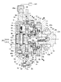
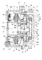
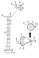
- FIG. 1 is a system configuration diagram of an internal combustion engine in an embodiment. It is a longitudinal cross-sectional view which shows the variable valve timing mechanism in embodiment. It is a principal part expanded sectional view of the main components in an electric variable valve timing mechanism.
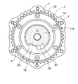
- FIG. 3 is a sectional view taken along line AA in FIG. 2.
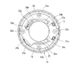
- FIG. 3 is a sectional view taken along line BB in FIG. It is a disassembled perspective view of the cover member and 1st oil seal which are provided to a variable valve timing mechanism same as the above.
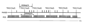
- FIG. 3 is a cross-sectional view taken along the line CC of FIG. It is a figure which shows the structure of the crank angle sensor and cam sensor in embodiment. It is a time chart which shows the output characteristic of the crank angle sensor and cam sensor in an embodiment.
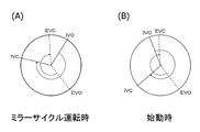
- the valve timing is controlled in the embodiment. (A) shows the mirror cycle operation after the start, and (B) shows the valve timing at the start.
- FIG. 1 is a configuration diagram of a vehicle internal combustion engine 101 to which an abnormality diagnosis device for a rotational phase detection device according to an embodiment of the present invention is applied.
- the internal combustion engine 101 is an in-line four-cylinder four-cycle engine, but is not limited to this example.
- an intake pipe 102 of an internal combustion engine 101 is provided with an electronically controlled throttle 103 that opens and closes a throttle valve 103b by a throttle motor 103a.
- the internal combustion engine 101 sucks air into the combustion chamber 106 of each cylinder via the electronic control throttle 103 and the intake valve 105.
- a fuel injection valve 131 is provided in the intake port 130 of each cylinder, and the fuel injection valve 131 is opened by an injection pulse signal from an ECU (engine control unit) 114 as a control device to inject fuel. To do.
- ECU engine control unit
- the fuel in the combustion chamber 106 is ignited and burned by spark ignition by the spark plug 104.
- Each ignition plug 104 is equipped with an ignition module 112 that incorporates an ignition coil and a power transistor that controls energization of the ignition coil.
- the combustion gas in the combustion chamber 106 flows out to the exhaust pipe 111 through the exhaust valve 107.
- a front catalytic converter 108 and a rear catalytic converter 109 provided in the exhaust pipe 111 purify exhaust flowing through the exhaust pipe 111.
- the intake cam shaft 134 and the exhaust cam shaft 110 are integrally provided with a cam, and the intake valve 105 and the exhaust valve 107 are operated by the cam.
- the valve timing of the intake valve 105 is variably controlled by a variable valve timing mechanism (electric VTC (Valve Timing Control)) 113 that rotates the intake camshaft 134 relative to the crankshaft 120 using an electric motor (actuator).
- VTC Valve Timing Control
- the electric VTC 113 is rotatably supported via a bearing 44 on a timing sprocket 1 that is a driving rotating body that is rotationally driven by a crankshaft 120 of an internal combustion engine, and a bearing 44,
- An intake camshaft 134 that rotates by the rotational force transmitted from the timing sprocket 1; a cover member 3 that is disposed at a front position of the timing sprocket 1 and is fixed to a chain cover 40 that is a fixing portion by a bolt;
- the phase changing mechanism 4 is disposed between the timing sprocket 1 and the intake camshaft 134 and is a variable mechanism that changes the relative rotational phase of the both 1, 134 according to the engine operating state. .
- the timing sprocket 1 is integrally formed of an iron-based metal, and an inner peripheral surface is integrally formed on the outer periphery of the sprocket body 1a and an annular sprocket body 1a. And a gear portion 1b that receives a rotational force from the crankshaft via the chain 42.
- the timing sprocket 1 is interposed between the circular groove 1c formed on the inner peripheral side of the sprocket body 1a and the outer periphery of the thick flange portion 2a provided integrally with the front end portion of the intake camshaft 134.
- the intake camshaft 134 is rotatably supported by a third ball bearing 43 which is a third bearing mounted.
- annular protrusion 1e is integrally formed on the outer peripheral edge of the front end portion of the sprocket body 1a.
- annular member 19 At the front end portion of the sprocket body 1a, there is an annular member 19 that is coaxially positioned on the inner peripheral side of the annular protrusion 1e and has an inner tooth 19a that is a wavy engagement portion formed on the inner periphery.
- the plate 6 is fixed together by bolts 7 from the axial direction.
- a stopper convex portion 1d which is an arcuate engagement portion, is formed on a part of the inner peripheral surface of the sprocket body 1a up to a predetermined length range along the circumferential direction. .
- a cylindrical housing 5 protruding forward in a state of covering components of a speed reducer 8 and an electric motor 12 (to be described later) of the phase change mechanism 4 is fixed to the outer periphery of the front end side of the plate 6 by bolts 11.
- the housing 5 is integrally formed of an iron-based metal and functions as a yoke.
- the housing 5 has an annular plate-shaped holding portion 5a integrally on the front end side, and the entire outer peripheral side including the holding portion 5a is
- the cover member 3 is disposed so as to be covered with a predetermined gap.
- the intake camshaft 134 has two drive cams per cylinder for opening the intake valve 105 on the outer periphery, and the driven member 9 that is a driven rotating body at the front end portion is coupled from the axial direction by the cam bolt 10. Yes. Further, as shown in FIG. 5, the flange portion 2a of the intake camshaft 134 has a stopper groove 2b, which is a locking portion into which the stopper protrusion 1d of the sprocket body 1a is engaged, along the circumferential direction. Is formed.
- the stopper concave groove 2b is formed in an arc shape having a predetermined length in the circumferential direction, and both end edges of the stopper convex portion 1d rotated in this length range abut against the circumferential opposite edges 2c and 2d, respectively.
- the relative rotational position of the intake cam shaft 134 on the maximum advance angle side or the maximum retard angle side with respect to the timing sprocket 1 is regulated.
- the cam bolt 10 is integrally formed with a flange-like seating surface portion 10c at an end edge of the head portion 10a on the shaft portion 10b side, and is formed on the outer periphery of the shaft portion 10b from the end portion of the intake camshaft 134 to the inner shaft direction.
- a male screw portion is formed to be screwed onto the formed female screw portion.
- the driven member 9 is integrally formed of an iron-based metal material, and as shown in FIG. 3, a disk portion 9a formed on the front end side, and a cylindrical cylindrical portion 9b formed integrally on the rear end side It is composed of
- the disc portion 9a is integrally provided with an annular step projection 9c having substantially the same outer diameter as that of the flange portion 2a of the intake camshaft 134 at a substantially central position in the radial direction of the rear end surface.
- the outer peripheral surface of the portion 2 a is inserted and arranged in the inner periphery of the inner ring 43 a of the third ball bearing 43.
- the outer ring 43b of the third ball bearing 43 is press-fitted and fixed to the inner peripheral surface of the circular groove 1c of the sprocket body 1a.
- a retainer 41 for holding a plurality of rollers 34 to be described later is integrally provided on the outer peripheral portion of the disc portion 9a.
- the cage 41 is formed to protrude from the outer peripheral portion of the disc portion 9a in the same direction as the cylindrical portion 9b, and has a plurality of elongated protrusion portions 41a having predetermined gaps at substantially equal intervals in the circumferential direction. Is formed by.
- the cylindrical portion 9 b has a through hole 9 d through which the shaft portion 10 b of the cam bolt 10 is inserted, and a first needle bearing described later which is a first bearing on the outer peripheral side. 30 is provided.
- the cover member 3 is integrally formed of a relatively thick synthetic resin material and swells in a cup shape, and an outer periphery of the rear end portion of the cover body 3a.
- the bracket 3b is formed integrally with the bracket 3b.
- the cover main body 3a is arranged so as to cover the front end side of the phase change mechanism 4, that is, to cover almost the entire rear end side from the axial holding portion 5b of the housing 5 with a predetermined gap.
- bolt insertion holes 3f are formed through six boss portions formed in a substantially annular shape.
- the bracket 3b of the cover member 3 is fixed to the chain cover 40 via a plurality of bolts 46, and the inner and outer double layers are formed on the inner peripheral surface of the front end 3e of the cover body 3a.
- Slip rings 48a and 48b are embedded and fixed with their inner end surfaces exposed.
- a connector portion 49 in which a connector terminal 49a connected to the slip rings 48a, 48b via a conductive member is fixed. The connector terminal 49a is energized or de-energized from a battery power source (not shown) via the ECU 114.
- a large-diameter first oil seal 50 which is a seal member, is interposed between the inner peripheral surface on the rear end side of the cover body 3a and the outer peripheral surface of the housing 5, as shown in FIG. Has been.
- the first oil seal 50 is formed in a substantially U-shaped cross section, a core metal is embedded in a synthetic rubber base material, and an annular base portion 50a on the outer peripheral side is formed at the rear end of the cover body 3a. It is fitted and fixed in a circular groove 3d formed on the inner peripheral surface of the part. Further, a seal surface 50b that comes into contact with the outer peripheral surface of the housing 5 is integrally formed on the inner peripheral side of the annular base portion 50a.
- the phase changing mechanism 4 includes an electric motor 12 disposed substantially coaxially on the front end side of the intake camshaft 134, and the speed reducer 8 that reduces the rotational speed of the electric motor 12 and transmits it to the intake camshaft 134. It is configured.
- the electric motor 12 is a brushed DC motor, and is provided in a housing 5 that is a yoke that rotates integrally with the timing sprocket 1, and is rotatably provided inside the housing 5.
- a motor shaft 13 which is an output shaft, a pair of semicircular arc permanent magnets 14 and 15 fixed to the inner peripheral surface of the housing 5, a stator 16 fixed to the inner bottom surface side of the housing holding portion 5a, It has.
- the motor shaft 13 is formed in a cylindrical shape and functions as an armature.
- An iron core rotor 17 having a plurality of poles is fixed to the outer periphery at a substantially central position in the axial direction, and an electromagnetic wave is provided on the outer periphery of the iron core rotor 17.
- a coil 18 is wound.
- a commutator 20 is press-fitted and fixed to the outer periphery of the front end portion of the motor shaft 13, and the electromagnetic coil 18 is connected to each segment divided into the same number as the number of poles of the iron core rotor 17. ing.
- the stator 16 includes an annular plate-shaped resin holder 22 fixed to the inner bottom wall of the holding portion 5a with four screws 22a, and the resin holder 22 and the holding portion 5a in the axial direction.
- the first brushes 23a, 23b in the circumferential direction are fed through and are fed in sliding contact with the pair of slip rings 48a, 48b, and inward and backward toward the inner peripheral side of the resin holder 22.
- the second brushes 24 a and 24 b that are freely held and the arcuate tip end slidably contacts the outer peripheral surface of the commutator 20 are mainly configured.
- the first brushes 23a, 23b and the second brushes 24a, 24b are connected to each other by pigtail harnesses 25a, 25b. Each is biased in the direction.
- the motor shaft 13 includes a needle bearing 28 serving as a first bearing on the outer peripheral surface of the shaft portion 10b on the head 10a side of the cam bolt 10 and a fourth ball bearing serving as a bearing disposed on an axial side portion of the needle bearing 28. 35 is rotatably supported via 35.
- a cylindrical eccentric shaft portion 30 constituting a part of the speed reducer 8 is integrally provided at the rear end portion of the motor shaft 13 on the intake cam shaft 134 side.
- the first needle bearing 28 includes a cylindrical retainer 28a that is press-fitted into the inner peripheral surface of the eccentric shaft portion 30, and needle rollers 28b that are a plurality of rolling elements that are rotatably held inside the retainer 28a. Has been.
- the needle roller 28 b rolls on the outer peripheral surface of the cylindrical portion 9 b of the driven member 9.
- the inner ring 35 a is fixed in a sandwiched state between the front end edge of the cylindrical portion 9 b of the driven member 9 and the seat surface portion 10 c of the cam bolt 10, while the outer ring 35 b is fixed to the inner periphery of the motor shaft 13.
- a friction member between the outer peripheral surface of the motor shaft 13 (eccentric shaft portion 30) and the inner peripheral surface of the plate 6 is a friction member that prevents leakage of lubricating oil from the inside of the reduction gear 8 into the electric motor 12.
- Two oil seals 32 are provided.
- the second oil seal 32 is configured to give a frictional resistance against the rotation of the motor shaft 13 by the inner peripheral portion being in elastic contact with the outer peripheral surface of the motor shaft 13.
- the speed reducer 8 includes the eccentric shaft portion 30 that performs an eccentric rotational motion, a second ball bearing 33 that is a second bearing provided on the outer periphery of the eccentric shaft portion 30, and The roller 34 provided on the outer periphery of the second ball bearing 33, the retainer 41 that allows the roller 34 to move in the radial direction while retaining the roller 34 in the rolling direction, and the follower integrated with the retainer 41
- the member 9 is mainly composed of.
- the axis Y of the cam surface formed on the outer peripheral surface is slightly eccentric from the axis X of the motor shaft 13 in the radial direction.
- the second ball bearing 33 and the roller 34 are configured as a planetary meshing portion.
- the second ball bearing 33 is formed in a large diameter, and is disposed so as to substantially overlap at the radial position of the first needle bearing 28, and the inner ring 33 a is press-fitted and fixed to the outer peripheral surface of the eccentric shaft portion 30.
- the roller 34 is always in contact with the outer peripheral surface of the outer ring 33b.
- an annular gap C is formed on the outer peripheral side of the outer ring 33b, and the entire second ball bearing 33 can be moved in the radial direction along with the eccentric rotation of the eccentric shaft portion 30 by this gap C. It is possible.
- Each roller 34 is fitted in the inner teeth 19a of the annular member 19 while moving in the radial direction along with the eccentric movement of the second ball bearing 33, and is guided in the circumferential direction by the protrusion 41a of the retainer 41 while having a diameter. It swings in the direction.
- Lubricating oil is supplied to the inside of the speed reducer 8 by lubricating oil supply means.
- this lubricating oil supply means is formed inside a bearing 44 of the cylinder head, and is provided with an oil supply passage 47 through which lubricating oil is supplied from a main oil gallery (not shown), and the intake camshaft 134.
- the oil supply hole 48 is formed in the direction of the inner axis of the oil supply passage 47 and communicates with the oil supply passage 47 via the groove groove.
- the oil supply hole 48 is formed so as to penetrate the oil supply hole 48 in the direction of the inner axis of the driven member 9.
- a small-diameter oil supply hole 45 whose other end is opened in the vicinity of the first needle bearing 28 and the second ball bearing 33 and three large-diameter oil discharge holes which are also formed through the driven member 9 and which are not shown. And is composed of.
- the ECU 114 When the electric VTC 113 is driven to change the rotational phase of the intake camshaft 134 (valve timing of the intake valve 105), the ECU 114 is energized to the electromagnetic coil 18 of the electric motor 12 via the slip rings 48a and 48b. The As a result, the motor shaft 13 is rotationally driven, and the rotational force of this rotational force is transmitted to the intake cam shaft 134 via the speed reducer 8.
- each roller 34 is guided by the protrusion 41 a of the retainer 41 in the radial direction for each rotation of the motor shaft 13.
- the robot moves over the inner teeth 19a while rolling to other adjacent inner teeth 19a, and repeats this in order to make rolling contact in the circumferential direction.
- the rotational force is transmitted to the driven member 9 while the rotation of the motor shaft 13 is decelerated by the rolling contact of the rollers 34.
- the reduction ratio at this time can be arbitrarily set according to the number of rollers 34 or the like.
- the intake camshaft 134 rotates forward and backward relative to the timing sprocket 1 and the relative rotational phase is converted, and the opening / closing timing of the intake valve is controlled to be advanced or retarded.
- each side surface of the stopper convex portion 1d is one of the opposing surfaces 2c and 2d of the stopper concave groove 2b. This is done by contacting one side.
- the driven member 9 rotates in the same direction as the rotation direction of the timing sprocket 1 as the eccentric shaft portion 30 rotates eccentrically, so that one side surface of the stopper convex portion 1d is opposed to one side of the stopper groove 2b. Further contact with the surface 2c is restricted from rotating in the same direction. As a result, the relative rotation phase of the intake camshaft 134 with respect to the timing sprocket 1 is changed to the maximum advance side.
- the ECU 114 has a built-in microcomputer, performs calculations according to a program stored in advance in a memory, and controls the electronic control throttle 103, the fuel injection valve 131, the ignition module 112, and the like.
- the ECU 114 inputs detection signals from various sensors.
- an accelerator opening sensor 116 that detects an opening (accelerator opening) ACC of an accelerator pedal 116a
- an airflow sensor 115 that detects an intake air amount Q of the internal combustion engine 101
- a crank that is an output shaft of the internal combustion engine 101
- a crank angle sensor (rotation sensor) 117 that outputs a pulsed rotation signal (unit crank angle signal) POS according to the rotation of the shaft 120
- a throttle sensor 118 that detects the opening TVO of the throttle valve 103b, and cooling of the internal combustion engine 101
- a water temperature sensor 119 for detecting the water temperature TW
- a cam sensor 133 for outputting a pulsed cam signal PHASE in accordance with the rotation of the intake camshaft 134
- a motor rotation sensor for detecting the motor shaft rotation angle of the electric motor for driving the electric VTC 113 201, the driver of the vehicle depresses the brake pedal 121
- a brake switch 122 which is turned on
- the ECU 114 inputs an on / off signal of an ignition switch 124 that is a main switch for operating / stopping the internal combustion engine 101 and an on / off signal of a starter switch 125.
- FIG. 8 shows the structure of the crank angle sensor 117 and the cam sensor 133.
- the crank angle sensor 117 is pivotally supported by the crankshaft 120 and has a signal plate 152 provided with a projection 151 as a detected portion around the crankshaft 120 and is fixed to the internal combustion engine 101 side.
- the crank angle sensor 117 detects the projection 151 and outputs a rotation signal POS. It is comprised with the rotation detection apparatus 153 to output.
- the rotation detection device 153 includes various processing circuits including a waveform generation circuit, a selection circuit, and the like together with a pickup that detects the protrusion 151, and the rotation signal POS output from the rotation detection device 153 is normally at a low level.
- This is a pulse signal composed of a pulse train that changes to a high level for a certain time when the protrusion 151 is detected.
- the protrusions 151 of the signal plate 152 are formed at equal intervals with a crank angle of 10 deg. However, a portion where the two protrusions 151 are continuously removed is sandwiched between the rotation center of the crankshaft 120. It is provided at two opposing locations. The number of protrusions 151 may be one, or three or more may be continuously deleted.
- the rotation signal POS output from the crank angle sensor 117 (the rotation detection device 153) has continuously changed to a high level 16 times every 10 degrees (unit crank angle) as shown in FIG. After that, the low level is maintained for 30 deg, and then continuously changes to the high level 16 times again.
- the first rotation signal POS after the low level period (tooth missing region, missing portion) having a crank angle of 30 deg is output at intervals of the crank angle of 180 deg. This corresponds to the stroke phase difference between the cylinders in the cylinder engine 101, in other words, the ignition interval.
- crank angle sensor 117 uses the piston position at 50 deg before top dead center of each cylinder (BTDC 50 deg.) After the low-level period (tooth loss region) at which the crank angle is 30 deg. It is set to output.
- the cam sensor 133 is pivotally supported at the end of the intake camshaft 134 and is fixed to the internal combustion engine 101 side with a signal plate 158 provided with a projection 157 as a detected portion around it, and detects the projection 157. And a rotation detecting device 159 that outputs a cam signal PHASE.
- the rotation detection device 159 includes various processing circuits including a waveform shaping circuit and the like together with a pickup that detects the protrusion 157.
- the projections 157 of the signal plate 158 are provided at one, three, four, and two, respectively, at four positions of 90 deg in cam angle.
- the pitch of 157 is set to 30 deg in crank angle (15 deg in cam angle).
- the cam signal PHASE output from the cam sensor 133 (rotation detection device 159) is normally at a low level, and is detected from a pulse train that changes to a high level for a certain time by detecting the protrusion 157.
- Each pulse signal is changed to a high level with a cam angle of 90 deg and a crank angle of 180 deg.
- a single cam signal PHASE and a head signal of a plurality of cam signals PHASE that are continuously output are output at an interval of 180 deg at the crank angle, and one single signal, three consecutive, and four consecutive Two consecutive output patterns are output between the top dead center TDC of one cylinder and the top dead center TDC of the next cylinder.
- the cam signal is estimated in consideration of the valve timing change range so that the output position of the cam signal PHASE does not change across the top dead center TDC.
- the output position and output interval of PHASE are set.
- cam signals PHASE are continuously output between the compression top dead center TDC of the first cylinder and the compression top dead center TDC of the third cylinder, and the compression top dead center TDC of the third cylinder
- cam signals PHASE are continuously output between the compression top dead center TDC of the fourth cylinder
- the cam signal PHASE is output between the compression top dead center TDC of the fourth cylinder and the compression top dead center TDC of the second cylinder.
- Two signals PHASE are continuously output, and one cam signal PHASE is output between the compression top dead center TDC of the second cylinder and the compression top dead center TDC of the first cylinder.
- the continuous output number of the cam signal PHASE output between each top dead center TDC indicates the cylinder number that will be the compression top dead center next. For example, between the current top dead center TDC and the previous top dead center TDC.
- the current top dead center TDC indicates the compression top dead center TDC of the third cylinder.
- the output pattern of the cam signal PHASE output between the top dead center TDC is As shown in FIG. 3, it is set in the order of single, three continuous, four continuous, and two continuous.
- the ECU 114 determines, for example, the missing position of the rotation signal POS from the periodic change of the rotation signal POS, and counts the number of occurrences of the rotation signal POS with reference to this missing position, thereby obtaining a top dead center TDC (reference Crank angle position) is detected.
- the sixth rotation signal POS output after the missing region of the rotation signal POS corresponds to the top dead center TDC of each cylinder.
- the ECU 114 counts the number of cam signals PHASE output between the top dead centers TDC, thereby determining the cylinder whose piston position will be the compression top dead center TDC (predetermined piston position) and top dead center.
- the number of occurrences of the rotation signal POS from the TDC is counted, and the crank angle at that time is detected based on the count value CNTPOS.
- the ECU 114 determines the cylinder that performs fuel injection and ignition, the fuel injection timing and the ignition timing, and the crankshaft that is detected based on the count value CNTPOS.
- An injection pulse signal and an ignition control signal are output according to the angle of 120 (crank angle).
- the discrimination result of the cylinder whose piston position becomes the compression top dead center TDC (predetermined piston position) is updated in the order of ignition, counting the number of outputs of the cam signal PHASE between the top dead centers TDC. Then, after the cylinder whose piston position is at the compression top dead center TDC (predetermined piston position) is determined, the cylinder at the compression top dead center TDC can be updated for each top dead center TDC in the order of ignition.
- the section for counting the number of occurrences of the cam signal PHASE is not limited to the top dead center TDC, and an arbitrary crank angle (piston position) is used as a reference for the section for counting the number of occurrences of the cam signal PHASE. be able to.
- the cylinder at the predetermined piston position can be determined based on the difference in the pulse width of the cam signal PHASE.
- a part of the pulse train of the rotation signal POS is missing, so that the angular position (crank angle) of the crankshaft 120 can be detected based on the missing position, but the rotation signal POS Is output without missing every 10 degrees, and instead, a reference position sensor that generates a signal at a reference crank angle position for every 180 degrees of crank angle is provided, and the rotation signal POS is counted based on the output signal of the reference position sensor.
- the angular position (crank angle) of the crankshaft 120 can also be detected.
- the electric VTC 113 by counting the number of occurrences of the rotation signal POS from the reference crank angle position to the single cam signal PHASE or the head signal of the plurality of cam signals PHASE output continuously.
- the rotational phase of the intake camshaft 134 relative to the crankshaft 120 (the actual valve timing of the intake valve 105) can be detected, and feedback control can be performed so that the valve timing approaches the target value based on this detected value. .
- the electric VTC 113 includes a motor rotation with a high detection frequency that can detect the rotation angle (rotation operation amount) of a driving electric motor (actuator) as a second driving source including the rotation direction at an arbitrary timing.
- a sensor (actuator rotation sensor) 201 is provided.
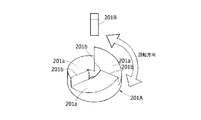
- the motor rotation sensor 201 includes a detected part 201A and a rotation angle detecting part 201B that is a gap sensor that detects displacement in the rotational direction of the detected part 201A.
- the detected part 201A is fitted and fixed to the front end edge of the motor shaft 13, and the rotation angle detecting part 201B is detected by the cover member 3 as shown in FIG. It is fixed by being inserted into a hole formed so as to penetrate a portion facing the front of 201A.
- the detected portion 201A is formed in a three-dimensional shape, and three target portions protruding in the axial direction are formed at equal intervals in the circumferential direction.
- an inclined portion 201a having an end face facing the rotation angle detecting portion 201B formed in an arc shape in the circumferential direction, and an edge portion 201b linearly cut from the end edge of the inclined portion 201a in the axial direction and in the radial direction. It is composed of
- Each inclined portion 201a is formed in a downward inclined surface shape at a predetermined angle from one end side with the edge portion 201b at the apex to the other end side in the clockwise direction, and the detection positions by the rotation angle detecting portion 201B are continuous. Changes.
- each of the edge portions 201b is formed so as to stand up along the radial direction, and is formed in a flat surface shape in the axial direction from one end of the inclined portion 201a, so that the detection position changes discontinuously. .
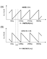
- the rotation angle detection unit 201B is of an electromagnetic pickup type, and detects a sloped part 201a and an edge part 201b of the opposed part 201A to be detected, thereby forming a continuous step shape (sawtooth shape) as shown in FIG.
- the waveform signal is output. That is, when the motor shaft 13 rotates in the clockwise direction, the output gradually increases when the inclined portion 201a is detected, and becomes a waveform signal that the output falls sharply when the edge portion 201b is detected (FIG. 11A). Is rotated in the counterclockwise direction, the output gradually decreases when the inclined portion 201a is detected, and becomes a waveform signal whose output rises sharply when the edge portion 201b is detected (FIG. 11B).
- the rotation angle of the motor shaft 13 in the clockwise direction (for example, the advance direction) is gradually increased according to the increase of the output, and when the output gradually decreases, the output
- the rotation angle (rotation operation amount) can be detected continuously (linearly) together with the rotation direction. It can. It should be noted that detection error can be suppressed by learning the output value (output voltage) of the corresponding rotation angle when the edge portion 201b is detected.
- the closing timing (IVC) of the intake valve 105 is largely retarded with respect to the intake bottom dead center (BDC) (or A mirror (Atkinson) cycle operation is performed by setting the valve timing to an advanced angle, and the expansion ratio is made larger than the effective compression ratio of the cylinder.
- BDC intake bottom dead center
- a mirror (Atkinson) cycle operation is performed by setting the valve timing to an advanced angle, and the expansion ratio is made larger than the effective compression ratio of the cylinder.
- the valve timing control is performed to reduce the retard amount (advance amount) of IVC and approach the BDC, thereby increasing the cylinder intake air amount. The operation will be ensured.
- the rotational phase (rotational angle position) of the intake camshaft 134 (second rotary body) with respect to the crankshaft 120 (first rotary body) changed by the electric VTC 113, that is, the valve timing of the intake valve 105 is from the cam sensor 133. Since it is detected for each stroke phase difference between cylinders based on the cam signal PHASE and the rotation signal POS from the crank angle sensor 117, the control period of the feedback control is set at the time of extremely low rotation such as at the start (during cranking). In comparison, the rotation phase detection period is long, the detection value is not updated between the previous control timing and the current control timing, and the rotation phase that is changed during this time cannot be detected with high accuracy.
- the ECU 114 basically includes signals from the cam sensor 133 and the crank angle sensor 117 constituting the rotation phase detection unit (first rotation detection unit), that is, the rotation angle position of the crankshaft 120 and the electric motor 12 (
- the motor rotation sensor 201 further detects the rotation phase of the intake camshaft 134 with respect to the crankshaft 120 based on the rotation angle position of the intake camshaft 134 that is rotated relative to the crankshaft 120 by an actuator.
- the valve timing of the intake valve 105 is detected at an arbitrary timing with high accuracy at the start, and the valve timing corresponding to the mirror cycle operation is determined.
- the advance angle is controlled to the valve timing for starting.
- the ECU 114 first determines the VTC target angle, that is, the target rotational phase of the intake camshaft 134 controlled by the electric VTC 113 (intake air) based on the operating state of the internal combustion engine (the engine that is the first drive source).
- Target valve timing the VTC target angle is set to the target valve timing for mirror operation shown in FIG. 12A during mirror cycle operation, but at the start time shown in FIG. It is set by switching to the target valve timing.
- the VTC actual angle that is, the rotational phase of the intake camshaft 134 is detected at predetermined intervals using the rotational phase detector, and if detected, the ECU 114 detects the final VTC actual angle.
- the obtained VTC actual angle is obtained.
- the relative rotation angle of the intake camshaft 134 with respect to the crankshaft 120 is detected by the motor rotation sensor 201 having a high detection frequency until the next actual VTC angle is detected.
- the motor shaft rotation angle (rotation operation amount) of the actuator that is, the change angle (VTC change angle) of the electric VTC 113 is detected.
- the ECU 114 sets the final VTC actual angle obtained last time as an initial value, and integrates the VTC change angle so as to interpolate a period until the next VTC actual angle is detected with respect to the initial value.
- the final VTC actual angle is obtained, and the motor operation amount is calculated such that the VTC actual angle follows the VTC target angle.
- the electric VTC 113 drives the electric motor 12 according to the motor operation amount, and the valve timing of the intake valve 105 is controlled to the valve timing for mirror operation in which IVC is sufficiently retarded during mirror cycle operation. At the time of starting, control is performed so that the valve timing is advanced for starting.
- the order of discriminating the cylinder at the predetermined piston position based on the cylinder discriminating value such as the number of occurrences of the cam signal PHASE or the difference in pulse width causes the fuel injection and ignition to be performed. Since it is performed by determining whether or not the order of the cylinders is in accordance, that is, by monitoring the order of the cylinder discrimination values, it takes a long time from the occurrence of the abnormality to the detection of the abnormality.
- the present embodiment based on the amount of change in rotational phase detected by the rotational phase detection unit for each predetermined period and the integrated value of the relative change angle detected by the motor rotation sensor 201 in the predetermined period.
- the presence / absence of abnormality of either the rotation phase detection unit or the motor rotation sensor 201 is determined.
- the absolute value of the deviation between the VTC actual angle detected by the rotational phase detector and the value obtained by integrating the VTC change angle detected by the motor rotation sensor 201 to the final VTC actual angle detected last time is predetermined.
- the value is equal to or larger than the value, it is determined that the rotation phase detection unit is abnormal, so that the abnormality of the rotation phase detection unit can be detected quickly.
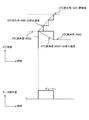
- the initial value of the actual VTC angle at the start is set according to the feedback control performed during the stop behavior before the start. That is, when feedback control is performed using the target VTC for mirror cycle operation during the stop behavior, it is assumed that the VTC actual angle has converged to the target VTC at the time of stop, and the initial value of the VTC actual angle at the start is set. It is set to the same value as the target VTC for the mirror cycle operation.
- the VTC actual angle is a value obtained by adding the VTC change angle detected by the motor rotation sensor 201 to the initial value (the integrated value of the VTC change angle).
- the VTC actual angle is replaced with the VTC actual angle detected by the rotation phase detection unit from the integrated value of the VTC change angle.
- the VTC actual angle is updated with a value obtained by integrating the VTC actual angle, and thereafter, every time the rotational phase detector detects the VTC actual angle, the VTC actual angle is replaced with the detected value while the VTC actual angle is replaced. Accumulated and updated to obtain the final VTC actual angle.
- the responsiveness at the start can be ensured by the feedback control at the start.
- the VTC actual angle detected by the rotation phase detector at the time of extremely low rotation during the stop behavior and the VTC change angle detected by the motor rotation sensor 201 are used to set the actual VTC angle at the time of stop to the target VTC for start-up.
- Feedback control for convergence can also be performed, and the actual VTC angle at the time of starting is brought close to the target VTC for starting, so that the starting performance as good as possible can be obtained from the start of the feedback control.
- the initial value of the VTC actual angle is an estimated value, and it is difficult to ensure sufficient accuracy until the VTC actual angle is detected for the first time by the rotation phase detector after the feedback control is started. If detection abnormality diagnosis is performed, it is difficult to ensure diagnostic accuracy. Therefore, the abnormality diagnosis is stopped during this period, and the abnormality diagnosis is started after the first actual VTC angle is detected by the rotation phase detection unit.
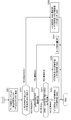
- FIG. 13 shows a flow of abnormality diagnosis processing at the time of valve timing control by the variable valve timing mechanism according to the first embodiment.
- the ECU 114 determines whether the motor rotation sensor 201 is abnormal.
- the abnormality diagnosis of the motor rotation sensor 201 is performed by monitoring the sensor output range or the sensor output change amount.
- step S101 If the ECU 114 determines that there is an abnormality in the motor rotation sensor 201 in step S101, the ECU 114 advances the process to step S107 and turns off the output of the motor operation amount as fail-safe control when the motor rotation sensor failure is confirmed. Thereby, when there is a failure in the motor rotation sensor 201, the drive of the VTC based on an incorrect motor operation amount can be suppressed.
- step S101 ECU 114 advances the process to step S102, and uses motor rotation sensor 201 to detect a VTC change angle (VAR) per unit time.
- step S103 the ECU 114 determines whether or not the actual VTC angle is detected by the rotational phase detection unit.
- step S103 If the actual VTC angle is not detected in step S103, the ECU 114 advances the process to step S106, and integrates the VTC change angle (VAR) detected in step S102 to the previous VTC actual angle (ANGF previous value). Then, the final VTC actual angle (ANGF final value) for calculating the motor operation amount is obtained.
- ANGF final value ANGF previous value + VAR
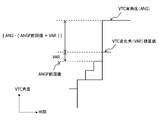
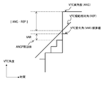
- step S104 the ECU 114 proceeds with the process to step S104, and as shown in FIG. 14, the VTC actual angle (ANG) and the previously obtained VTC actual angle (ANGF). It is determined whether or not the absolute value of the deviation from the value obtained by integrating the VTC change angle (VAR) detected in step S102 to the previous value is equal to or greater than a predetermined value.
- ⁇ predetermined value In other words, in step S104, the ECU 114 detects the amount of change in the actual VTC angle (rotation phase) detected by the rotation phase detection unit for each predetermined period, and the motor rotation.
- the VTC change angle calculated by the motor rotation sensor 201 is obtained from the previously obtained VTC actual angle (initial value) in order to remove an error caused by integration with the VTC actual angle.
- the VTC actual angle in a period in which the VTC actual angle is not detected is interpolated as the change amount of the current VTC.
- the motor operation amount is calculated based on the current VTC actual angle.
- the absolute value of the deviation becomes equal to or greater than a predetermined value (threshold for abnormality determination) based on the absolute value of the deviation.
- the rotational phase detection unit is determined to be abnormal.
- step S101 since it is determined in step S101 that there is no abnormality in the motor rotation sensor 201, the VTC change angle (VAR) based on the signal from the motor rotation sensor is normally obtained by the VTC previously obtained by the rotation phase detection unit. If the absolute value of the deviation between the value integrated with the actual angle (ANGF previous value) and the VTC actual angle (ANG) detected in step S103 is less than a predetermined value, it is determined that there is no abnormality in the rotational phase detector. be able to.
- step S104 determines in step S104 that the absolute value of the deviation is equal to or greater than the predetermined value
- the ECU 114 proceeds with the process to step S106.
- step S106 the ECU 114 detects the VTC actual angle detected in step S102 as the last detected VTC actual angle (ANGF previous value), as described above, as failsafe control when the rotational phase detection unit is abnormal.
- step S104 when the absolute value of the deviation is less than a predetermined value, the ECU 114 determines that there is no abnormality in the rotational phase detection unit. Thereafter, the ECU 114 proceeds with the process to step S105, obtains the final VTC actual angle (ANGF final value) as the VTC actual angle (ANG) detected in step S103, and feedback of normal valve timing based on the VTC actual angle. Take control.
- VTC actual angle (ANGF final value) VTC actual angle (ANG)
- step S106 sets the final VTC actual angle to the VTC actual angle (ANGF) obtained in step S105, and the VTC calculated in step S102.
- VAR change angle
- an abnormality in the rotational phase detection unit is quickly detected by making a comparative determination using the motor rotation sensor 201 having a higher detection frequency than the rotational phase detection unit having a long detection cycle. be able to. Moreover, since it shifts to fail safe control which continues normal VTC drive control from the time of detecting an abnormality, it is possible to avoid calculating an incorrect motor operation amount in the feedback control of the valve timing, so an overshoot with respect to the target can be avoided. Can be suppressed in advance. Thereby, engine performance is impaired, and it is possible to suppress the occurrence of secondary failures such as a decrease in the durability of the stopper due to the electric VTC 113 and adhesion to the stopper.
- FIG. 15 shows a flow of abnormality diagnosis processing during valve timing control by the variable valve timing mechanism according to the second embodiment.
- the rotation phase detection unit is normal in step S104, whereas the rotation phase detection unit is normal. After confirming this, the presence / absence of abnormality of the motor rotation sensor 201 is determined by the same abnormality diagnosis method.
- the ECU 114 does not perform the abnormality diagnosis of the motor rotation sensor 201 performed in step S101 of the first embodiment, and following the calculation of the VTC change angle in steps S201 and S202 as in steps S102 and S103. It is determined whether the VTC actual angle is detected. If the VTC actual angle is not detected in step S202, the ECU 114 proceeds with the process to step S208. In step S208, the ECU 114 adds the VTC change angle to the previously obtained VTC actual angle (ANGF previous value) and proceeds to the final VTC actual angle (ANGF final value) in the same manner as the process proceeds from step S103 to S106. And the drive control of the VTC is continued.
- step S203 the ECU 114 determines whether or not the order of cylinder discrimination is in accordance with the above-described abnormality diagnosis of the conventional rotational phase detector, that is, based on the cam signal PHASE from the cam sensor 133.
- step S203 If the ECU 114 determines in step S203 that the rotational phase detection unit is abnormal, the ECU 114 proceeds with the process to step S207, and performs fail-safe control for turning off the motor operation amount output and stopping the drive control of the VTC. Thereby, the drive of VTC based on the incorrect motor operation amount can be suppressed.
- step S203 the ECU 114 determines that there is no abnormality in step S203, the ECU 114 proceeds with the process to step S204, and performs an abnormality diagnosis similar to step S104 of the first embodiment.
- the ECU 114 determines that there is an abnormality in the motor rotation sensor 201 when the absolute value of the deviation is greater than or equal to a predetermined value in step S204. It is determined that there is, and the process proceeds to step S206.
- step S206 the ECU 114 obtains the final VTC actual angle (ANGF final value) as the VTC actual angle (ANG) calculated in step S202.
- step S204 determines in step S204 that there is no abnormality in the motor rotation sensor 201
- the process proceeds to step S205, and the VTC actual angle detected in step S203 is set as the final VTC actual angle in the same manner as in step S105. To do.
- the absolute value of the deviation based on the VTC actual angle and the VTC change angle (
- 16 and 17 show a flow of abnormality diagnosis processing at the time of valve timing control by the variable valve timing mechanism according to the third embodiment.
- the third embodiment when an abnormality occurs in both the rotation phase detection unit and the motor rotation sensor 201, that is, the abnormality diagnosis of the rotation phase detection unit is performed while taking into account a double failure, the abnormality diagnosis and fail-safe control other than the abnormality diagnosis and various fail-safe controls performed in the second embodiment are also performed.
- step S301 as in step S203 of the second embodiment, the ECU 114 performs abnormality diagnosis of the rotational phase detection unit by monitoring the conventional cylinder discrimination order. If the ECU 114 determines in step S301 that there is an abnormality, the process proceeds to step S310 shown in FIG. 17, and abnormality diagnosis of the motor rotation sensor 201 is performed in the same manner as in step S101 in FIG.
- step S310 if the ECU 114 determines that there is no abnormality in the motor rotation sensor 201, the process proceeds to step S311 and performs fail-safe control when the rotation phase detection unit failure is confirmed.
- VAR VTC change angle
- ANGF previous value VTC actual angle
- step S310 if there is an abnormality in the motor rotation sensor 201 in step S310, that is, if an abnormality has occurred in both the rotation phase detector and the motor rotation sensor 201, the ECU 114 performs fail-safe control when a double failure is confirmed.
- the fixed operation amount for fixing the electric VTC 113 at the stopper position is output, or the output of the motor operation amount is turned off, thereby suppressing the lowering of the durability of the stopper and the sticking due to the erroneous motor operation amount. it can.
- step S301 if the ECU 114 determines in step S301 that there is no abnormality in the rotational phase detection unit, the ECU 114 proceeds with the process to step S302, and performs an abnormality diagnosis of the motor rotation sensor 201 as in step S101 of the first embodiment. . If there is an abnormality in step 302, the ECU 114 proceeds with the process to step S309, and performs fail-safe control when the motor rotation sensor failure is confirmed.
- step S107 of the first embodiment in addition to turning off the output of the motor operation amount, by limiting the output of the motor operation amount, The influence on the engine performance by the fail-safe control can be minimized.
- step S301 since it is determined in step S301 that there is no abnormality in the rotational phase detector, the drive control of the VTC may be continued only with the actual VTC angle detected by the rotational phase detector. At this time, since the detection cycle of the final VTC actual angle changes, the control gain used for driving the electric VTC 113 is switched to stabilize the driving control of the electric VTC 113, so that the influence on the engine performance by the fail-safe control is affected. Can be minimized.
- step S301 it is determined in step S301 that there is no abnormality in the rotational phase detection unit, noise may be detected in the signal output from the rotational phase detection unit.
- the ECU 114 turns off the output of the motor operation amount.
- step S302 If the ECU 114 determines in step S302 that there is no abnormality in the motor rotation sensor 201, the process proceeds to step S303.
- steps S303 and S304 the ECU 114 calculates the VTC change angle (step S303), similarly to steps S102 and S103 of the first embodiment, and determines whether or not the VTC actual angle is detected (step S304).
- step S304 if the VTC actual angle is not detected, the ECU 114 proceeds with the process to step S308, and similarly to step S106 of the first embodiment, the previously obtained VTC actual angle (ANGF previous value) and the VTC change angle ( VAR), a final VTC actual angle is obtained, and feedback control of normal valve timing based on the VTC actual angle is performed.
- VTC actual angle ANGF previous value
- VAR VTC change angle
- step S304 when the VTC actual angle is detected, the ECU 114 proceeds with the process to step S305, and performs abnormality diagnosis of the rotational phase detection unit.
- the VTC actual angle (ANG) detected in step S304 and the previous VTC actual angle (ANGF previous value) are integrated with the VTC change angle (VAR) calculated in step S303.
- Whether or not there is an abnormality in the rotational phase detection unit may be determined by determining whether or not the absolute value of the deviation from the value is greater than or equal to a predetermined value, but in the third embodiment, other abnormality diagnosis methods Will be described.
- the abnormality diagnosis of the rotation phase detection unit is performed by each abnormality diagnosis method described later, but may be applied to the abnormality diagnosis of the motor rotation sensor 201 performed in step S204 of the second embodiment. .
- the change speed (inclination) between the VTC actual angle detected last time and the VTC actual angle detected this time, and a plurality of times from the time when the VTC actual angle was detected to the current detection.
- a predetermined value threshold for abnormality determination
- the ECU 114 changes the VTC actual angle (rotation phase) detected by the rotation phase detection unit every predetermined cycle and the predetermined change in the VTC change angle (relative change angle) detected by the motor rotation sensor 201. It is determined whether or not the absolute value of the deviation from the rotational phase change speed calculated based on the integrated value in the period is equal to or greater than a predetermined value.
- the motor rotation sensor 201 is normal and the VTC is output until the current VTC actual angle is detected until the motor operation amount (duty) is output in the direction in which the VTC actual angle increases. Assume that the angle of change increases. At this time, there is a case where the actual VTC angle that decreases the angle is erroneously detected this time due to the occurrence of an abnormality in the rotational phase detector.
- the application direction of the motor operation amount (duty) calculated based on the VTC change angle detected by the motor rotation sensor 201 that is, the relative rotation direction of the intake camshaft 134 with respect to the crankshaft 120 according to the operation amount
- the rotation A configuration may be adopted in which the presence or absence of an abnormality is determined based on whether or not the relative rotation direction of the intake camshaft 134 obtained based on the current VTC actual angle (rotation phase) detected by the phase detection unit is different.
- the intake camshaft 134 is obtained based on the relative rotation direction of the intake camshaft 134 according to the operation amount and the integrated value in a predetermined cycle of the VTC change angle (relative change angle) detected by the motor rotation sensor 201. If the relative rotation directions of the motor rotation sensors 201 do not coincide with each other, it can be determined that the motor rotation sensor 201 is abnormal.
- a reference model an internal model for driving control of an actuator
- VTC reference relative angle that changes following a change in a VTC target angle
- the absolute value of the deviation between the VTC reference relative angle (REF) (change amount in a predetermined cycle) calculated by the calculation unit and the VTC actual angle (ANG) (change amount in rotational phase) detected this time is a predetermined value (abnormality determination). It is good also as a structure which determines the presence or absence of abnormality by whether it is more than (threshold for use).
- the absolute value of the deviation between the VTC reference relative angle (REF) and the actual VTC angle (rotation phase) calculated based on the integrated value of the VTC change angle detected by the motor rotation sensor 201 in a predetermined cycle is When the value is equal to or greater than the predetermined value, it can be determined that the motor rotation sensor 201 is abnormal.
- step S305 when ECU 114 determines that there is no abnormality in the rotational phase detector by any of the methods described above, the process proceeds to step S306.
- step S306 the ECU 114 obtains the final VTC actual angle (ANGF final value) as the VTC actual angle (ANG) detected in step S304, and performs normal valve timing feedback control based on the VTC actual angle.
- the ECU 114 changes the final VTC actual angle to the VTC actual angle (ANGF) obtained in step S306 in step S308.
- the VTC change angle (VAR) calculated in step 1 is obtained as an integrated value, and feedback control is performed.
- step S305 determines in step S305 that there is an abnormality in the rotational phase detection unit
- the process proceeds to step S307 and performs fail-safe control when an abnormality occurs in the rotational phase detection unit.
- step S307 the VTC actual angle (angf previous value) is changed from the final VTC actual angle to the previous VTC actual angle (angf previous value), as in the case of proceeding from step S104 to step S106 of the first embodiment.
- the normal VTC drive control is continued as an integrated value of VAR), or the fail-safe control such as limiting or turning off the motor operation amount output or outputting the fixed operation amount is performed as in the case of the motor rotation sensor failure determination. You may go.
- the output may be switched step by step so that the output is limited ⁇ the output of the fixed operation amount ⁇ the output of the motor operation amount is turned off.
- VTC drive control continues (the absolute value of the deviation is small) ⁇ the output limit of the motor operation amount (the absolute value of the deviation) Middle) ⁇ Fail-safe control may be switched step by step so that the output of the fixed operation amount or the output of the motor operation amount is turned off (the absolute value of the deviation is large).
- the influence on the engine performance can be suppressed by switching the fail-safe control step by step according to the number or degree of abnormality determination in step S305.
- abnormality diagnosis of the rotation phase detection unit is performed while taking into account a double failure in which an abnormality occurs in both the rotation phase detection unit and the motor rotation sensor, but this is performed in the first and second embodiments.
- the abnormality diagnosis and various fail-safe controls other than the abnormality diagnosis and various fail-safe controls have been described.
- any of the embodiments based on the rotation phase detection unit and the motor rotation sensor that is detected more frequently than the rotation phase detection unit, it is possible to determine the presence or absence of each other and quickly detect the abnormality. Can do.
- an abnormality it is possible to prevent the occurrence of an overshoot with respect to a target based on the motor operation amount by avoiding an erroneous motor operation amount being calculated by shifting to fail-safe control. .
- secondary failure such as a decrease in the durability of the stopper due to a strong hit of the valve timing mechanism and sticking to the stopper can be suppressed.
- the abnormality diagnosis is performed at the time of extremely low engine rotation such as at the time of starting and at the time of stopping behavior, but the detection cycle by the rotation phase detection unit is short at the time of engine high rotation exceeding a predetermined value. Since the possibility that the deviation becomes large is not so high, the abnormality diagnosis according to each embodiment may not be performed. Thereby, at the time of high engine rotation, the calculation load can be reduced by abnormality diagnosis.
- the fail-safe control is performed if normal determination continues by subsequent abnormality diagnosis. May be released.
- valve timing for the mirror cycle operation of the intake valve and the control for switching between the valve timing for starting is shown, but even in an engine that does not perform the mirror cycle operation, The valve timing for starting can be set optimally.
- the present invention can be applied to control the exhaust valve to a valve timing suitable for starting at the time of starting or stopping behavior.
- the abnormality diagnosis device for the rotational phase detection device is applied to the control device for the variable valve timing mechanism.
- the present invention is not limited to this.
- a first rotation detecting unit configured to detect a rotation phase of the second rotating body relative to the first rotating body based on a rotation angle position of the second rotating body rotating relative to the rotating body; and the second rotating body. Applicable to any object that includes a second rotation detection unit that detects a relative change angle of the first rotation body with a frequency higher than a detection frequency of the first rotation detection unit. it can.
Landscapes
- Engineering & Computer Science (AREA)
- Mechanical Engineering (AREA)
- General Engineering & Computer Science (AREA)
- Chemical & Material Sciences (AREA)
- Combustion & Propulsion (AREA)
- Valve Device For Special Equipments (AREA)
- Output Control And Ontrol Of Special Type Engine (AREA)
- Combined Controls Of Internal Combustion Engines (AREA)
Abstract
検出頻度の異なる2つの回転検出部のいずれかに異常が発生したときに、該異常を速やかにかつ高精度に検出でき、低回転時の異常に良好に対応できるようにすることを目的とする。回転位相検出部により検出したVTC実角度と、モータ回転センサ201により前記回転位相検出部によるVTC実角度の検出頻度より高い頻度で検出したVTC変化角の積算値との偏差の絶対値が所定値以上のときに、前記回転位相検出部に異常があると判定する。
Description
本発明は、回転位相検出装置の異常診断装置及び方法とそれを用いた回転位置制御装置に関し、例えば、内燃機関の機関バルブ(吸気バルブまたは排気バルブ)のバルブタイミングを変更する可変バルブタイミング機構の制御装置に前記回転位相検出装置の異常診断装置を適用したものに関する。
例えば、可変バルブタイミング機構の制御装置では、回転検出部によりクランク軸に対するカム軸の回転位相(回転角位置)を検出しつつ、可変バルブタイミング機構によって目標回転位相に近づけることにより、バルブタイミングを制御している。
特許文献1では、電動モータを用いて吸気バルブ開閉用カム軸を駆動する可変バルブタイミング機構において、上記の回転検出部に比較して、検出頻度が高いモータ軸の回転信号を用いることにより、機関低速域での精度の良いバルブタイミング制御の実現を図っている。
特許文献1では、電動モータを用いて吸気バルブ開閉用カム軸を駆動する可変バルブタイミング機構において、上記の回転検出部に比較して、検出頻度が高いモータ軸の回転信号を用いることにより、機関低速域での精度の良いバルブタイミング制御の実現を図っている。
しかしながら、特許文献1では、機関の始動時や停止直前の極低回転時に回転検出部に1回でも異常が発生すると、回転位相、すなわち吸気バルブのバルブタイミングを誤検出してしまうことがあり、該誤検出に基づく誤ったモータ操作量によりバルブタイミング機構の駆動制御が継続されて、バルブタイミングが目標値に対して大きくオーバーシュートしてしまうことがあった。その結果、エンジン性能(特に低回転性能)が損なわれ、バルブタイミング機構の可動部品の強い当たりによるストッパの耐久性低下及び可動部品のストッパへの固着等の二次故障が発生するおそれがある。
また、従来の回転検出部の異常診断は、カム軸に設けられたカムセンサの気筒判別値の順番監視により行っており、異常が発生してから異常を検出するまで長い期間を要するため、その間、上記と同様に誤ったモータ操作量に基づくオーバーシュートが発生してしまうことにより、同じくエンジン性能が損なわれ、ストッパの耐久性低下及び固着等の二次故障が発生するおそれがある。
本発明は、このような従来の課題に着目してなされたもので、検出頻度の異なる2つの回転検出部のいずれかに異常が発生したときに、該異常を速やかにかつ高精度に検出でき、低回転時の異常に良好に対応できるようにすることを目的とする。
本発明の一側面によると、第1回転体の回転角位置と、アクチュエータによって前記第1回転体に対して相対回転する第2回転体の回転角位置とに基づいて、前記第1回転体に対する前記第2回転体の回転位相を所定の周期毎に検出する第1回転検出部と、前記アクチュエータによる前記第2回転体の前記第1回転体に対する相対変化角を、前記第1回転検出部による検出頻度より高い頻度で検出する第2回転検出部と、を含む回転位相検出装置の異常診断装置は、前記第1回転検出部により検出される前記回転位相の変化量と、前記第2回転検出部により検出される前記相対変化角の所定の周期における積算値とに基づいて、前記第1回転検出部と前記第2回転検出部とのいずれか一方の異常の有無を判定する。
また、本発明の一側面によると、回転体の回転位置制御装置は、上記回転位相検出装置の異常診断装置を含み、前記回転位相検出装置の異常診断装置によって前記第1回転検出部と前記第2回転検出部のいずれか一方が異常であると判定されたとき、他方の検出部の検出値に基づき算出された第2回転体の回転位相に応じて、前記アクチュエータによる前記第2回転体の駆動制御を継続すること、又は前記アクチュエータを駆動する操作量の出力を制限し又は停止する。
前記回転位相検出装置の異常診断装置によれば、第1回転検出部又は第2回転検出部に異常が発生した場合、双方の検出値に基づいて速やかにかつ高精度に異常を検出することができる。
また、前記回転体の回転位置制御装置によれば、回転位相検出装置の異常診断装置により前記第1回転検出部と前記第2回転検出部のいずれか一方が異常であると判定されたとき、他方の検出部の検出値に基づき算出された第2回転体の回転位相に基づいて、上記第2回転体の駆動制御のフェールセーフ処理が行われる。
これにより、異常な回転位相の検出値により第2回転体の回転位相が目標値に対してオーバーシュートして好ましくない回転位相に制御されることを抑制できる。
また、前記回転体の回転位置制御装置によれば、回転位相検出装置の異常診断装置により前記第1回転検出部と前記第2回転検出部のいずれか一方が異常であると判定されたとき、他方の検出部の検出値に基づき算出された第2回転体の回転位相に基づいて、上記第2回転体の駆動制御のフェールセーフ処理が行われる。
これにより、異常な回転位相の検出値により第2回転体の回転位相が目標値に対してオーバーシュートして好ましくない回転位相に制御されることを抑制できる。
以下、本発明の一実施形態を添付図面に基づいて説明する。
図1は、本発明の実施形態による回転位相検出装置の異常診断装置を適用した車両用内燃機関101の構成図である。尚、本実施形態において、内燃機関101は、直列4気筒の4サイクル機関であるが、本例に限定されない。
図1は、本発明の実施形態による回転位相検出装置の異常診断装置を適用した車両用内燃機関101の構成図である。尚、本実施形態において、内燃機関101は、直列4気筒の4サイクル機関であるが、本例に限定されない。
図1において、内燃機関101の吸気管102には、スロットルモータ103aでスロットルバルブ103bを開閉駆動する電子制御スロットル103を介装してある。
そして、内燃機関101は、電子制御スロットル103及び吸気バルブ105を介して、各気筒の燃焼室106内に空気を吸入する。
そして、内燃機関101は、電子制御スロットル103及び吸気バルブ105を介して、各気筒の燃焼室106内に空気を吸入する。
各気筒の吸気ポート130に、燃料噴射弁131を設けてあり、燃料噴射弁131は、制御装置としてのECU(エンジン・コントロール・ユニット)114からの噴射パルス信号によって開弁動作し、燃料を噴射する。
燃焼室106内の燃料は、点火プラグ104による火花点火によって着火燃焼する。点火プラグ104それぞれには、点火コイル及び該点火コイルへの通電を制御するパワートランジスタを内蔵した点火モジュール112を装着してある。
燃焼室106内の燃焼ガスは、排気バルブ107を介して排気管111に流出する。排気管111に設けたフロント触媒コンバータ108及びリア触媒コンバータ109は、排気管111を流れる排気を浄化する。
吸気カム軸134、排気カム軸110は、一体的にカムを備え、このカムによって吸気バルブ105及び排気バルブ107を動作させる。
吸気バルブ105のバルブタイミングは、電動モータ(アクチュエータ)を用いて吸気カム軸134をクランク軸120に対して相対回転させる可変バルブタイミング機構(電動VTC(Valve Timing Control))113により、可変に制御される。
吸気バルブ105のバルブタイミングは、電動モータ(アクチュエータ)を用いて吸気カム軸134をクランク軸120に対して相対回転させる可変バルブタイミング機構(電動VTC(Valve Timing Control))113により、可変に制御される。
上記電動VTC113は、図2~図7に示すように、内燃機関のクランク軸120によって回転駆動する駆動回転体であるタイミングスプロケット1と、シリンダヘッド上に軸受44を介して回転自在に支持され、前記タイミングスプロケット1から伝達された回転力によって回転する吸気カム軸134と、該タイミングスプロケット1の前方位置に配置されて、固定部であるチェーンカバー40にボルトによって取り付け固定されたカバー部材3と、前記タイミングスプロケット1と吸気カム軸134の間に配置されて、機関運転状態に応じて両者1、134の相対回転位相を変更する可変機構である位相変更機構4と、を備えて構成されている。
タイミングスプロケット1は、全体が鉄系金属によって一体に形成され、内周面が段差径状の円環状のスプロケット本体1aと、該スプロケット本体1aの外周に一体に設けられて、巻回されたタイミングチェーン42を介してクランク軸からの回転力を受けるギア部1bと、から構成されている。また、タイミングスプロケット1は、前記スプロケット本体1aの内周側に形成された円形溝1cと前記吸気カム軸134の前端部に一体に設けられた肉厚なフランジ部2aの外周との間に介装された第3軸受である第3ボールベアリング43によって吸気カム軸134に回転自在に支持されている。
スプロケット本体1aの前端部外周縁には、環状突起1eが一体に形成されている。このスプロケット本体1aの前端部には、前記環状突起1eの内周側に同軸に位置決めされ、内周に波形状の噛み合い部である内歯19aが形成された環状部材19と、大径円環状のプレート6とがボルト7によって軸方向から共締め固定されている。また、前記スプロケット本体1aの内周面の一部には、図5に示すように、円弧状の係合部であるストッパ凸部1dが周方向に沿って所定長さ範囲まで形成されている。
プレート6の前端側外周には、前記位相変更機構4の後述する減速機8や電動モータ12の各構成部材を覆う状態で前方に突出した円筒状のハウジング5がボルト11によって固定されている。
ハウジング5は、鉄系金属によって一体に形成されてヨークとして機能し、前端側に円環プレート状の保持部5aを一体に有していると共に、該保持部5aを含めた外周側全体が前記カバー部材3によって所定の隙間をもって覆われた形で配置されている。
吸気カム軸134は、外周に吸気バルブ105を開作動させる一気筒当たり2つの駆動カムを有していると共に、前端部に従動回転体である従動部材9がカムボルト10によって軸方向から結合されている。また、吸気カム軸134の前記フランジ部2aには、図5に示すように、前記スプロケット本体1aのストッパ凸部1dが係入する係止部であるストッパ凹溝2bが円周方向に沿って形成されている。このストッパ凹溝2bは、円周方向へ所定長さの円弧状に形成されて、この長さ範囲で回動したストッパ凸部1dの両端縁が周方向の対向縁2c、2dにそれぞれ当接することによって、タイミングスプロケット1に対する吸気カム軸134の最大進角側あるいは最大遅角側の相対回転位置を規制するようになっている。
カムボルト10は、頭部10aの軸部10b側の端縁にフランジ状の座面部10cが一体に形成されていると共に、軸部10bの外周に前記吸気カム軸134の端部から内部軸方向に形成された雌ねじ部に螺着する雄ねじ部が形成されている。
従動部材9は、鉄系金属材によって一体に形成され、図3に示すように、前端側に形成された円板部9aと、後端側に一体に形成された円筒状の円筒部9bとから構成されている。
円板部9aは、後端面の径方向ほぼ中央位置に前記吸気カム軸134のフランジ部2aとほぼ同外径の環状段差突起9cが一体に設けられ、この段差突起9cの外周面と前記フランジ部2aの外周面が前記第3ボールベアリング43の内輪43aの内周に挿通配置されている。第3ボールベアリング43の外輪43bは、スプロケット本体1aの円形溝1cの内周面に圧入固定されている。
また、円板部9aの外周部には、図2~図6に示すように、後述する複数のローラ34を保持する保持器41が一体に設けられている。この保持器41は、前記円板部9aの外周部から前記円筒部9bと同じ方向へ突出して形成され、円周方向へほぼ等間隔の位置に所定の隙間をもった複数の細長い突起部41aによって形成されている。
円筒部9bは、図2に示すように、中央に前記カムボルト10の軸部10bが挿通される挿通孔9dが貫通形成されていると共に、外周側に第1軸受である後述の第1ニードルベアリング30が設けられている。
カバー部材3は、図2及び図6に示すように、比較的に肉厚な合成樹脂材によって一体に形成され、カップ状に膨出したカバー本体3aと、該カバー本体3aの後端部外周に一体に形成されたブラケット3bと、から構成されている。
カバー本体3aは、位相変更機構4の前端側を覆う、つまりハウジング5の軸方向の保持部5bから後端部側のほぼ全体を、所定隙間をもって覆うように配置されている。一方、前記ブラケット3bには、ほぼ円環状に形成された6つのボス部にそれぞれボルト挿通孔3fが貫通形成されている。
また、図2に示すように、カバー部材3のブラケット3bが前記チェーンカバー40に複数のボルト46を介して固定されていると共に、前記カバー本体3aの前端部3eの内周面に内外2重のスリップリング48a、48bが各内端面を露出した状態で埋設固定されている。さらに上端部には、内部に前記スリップリング48a、48bと導電部材を介して接続されたコネクタ端子49aが固定されたコネクタ部49が設けられている。なお、前記コネクタ端子49aには、ECU114を介して図外のバッテリー電源から通電あるいは通電が遮断されるようになっている。
そして、カバー本体3aの後端部側の内周面と前記ハウジング5の外周面との間には、図2にも示すように、シール部材である大径な第1オイルシール50が介装されている。この第1オイルシール50は、横断面ほぼコ字形状に形成されて、合成ゴムの基材の内部に芯金が埋設されていると共に、外周側の円環状基部50aが前記カバー本体3a後端部の内周面に形成された円形溝3d内に嵌着固定されている。また、円環状基部50aの内周側には、前記ハウジング5の外周面に当接するシール面50bが一体に形成されている。
位相変更機構4は、吸気カム軸134のほぼ同軸上前端側に配置された電動モータ12と、該電動モータ12の回転速度を減速して吸気カム軸134に伝達する前記減速機8と、から構成されている。
電動モータ12は、図2及び図3に示すように、ブラシ付きのDCモータであって、タイミングスプロケット1と一体に回転するヨークであるハウジング5と、該ハウジング5の内部に回転自在に設けられた出力軸であるモータ軸13と、ハウジング5の内周面に固定された半円弧状の一対の永久磁石14、15と、ハウジング保持部5aの内底面側に固定された固定子16と、を備えている。
モータ軸13は、筒状に形成されてアーマチュアとして機能し、軸方向のほぼ中央位置の外周に、複数の極を持つ鉄心ロータ17が固定されていると共に、該鉄心ロータ17の外周には電磁コイル18が巻回されている。また、モータ軸13の前端部外周には、コミュテータ20が圧入固定されており、このコミュテータ20には、前記鉄心ロータ17の極数と同数に分割された各セグメントに前記電磁コイル18が接続されている。
固定子16は、図7に示すように、保持部5aの内底壁に4本のビス22aによって固定された円環板状の樹脂ホルダー22と、該樹脂ホルダー22と保持部5aを軸方向に貫通配置されて、各先端面が前記一対のスリップリング48a、48bに摺接して給電される周方向内外2つの第1ブラシ23a、23bと、樹脂ホルダー22の内周側に内方へ進退自在に保持されて、円弧状の先端部が前記コミュテータ20の外周面に摺接する第2ブラシ24a、24bと、から主として構成されている。
第1ブラシ23a、23bと第2ブラシ24a、24bは、ピッグテールハーネス25a、25bによって接続されていると共に、それぞれに弾接した捩りばね26a、27aのばね力によってスリップリング48a、48b方向やコミュテータ20方向へそれぞれ付勢されている。
モータ軸13は、カムボルト10の頭部10a側の軸部10bの外周面に第1軸受であるニードルベアリング28と該ニードルベアリング28の軸方向の側部に配置された軸受である第4ボールベアリング35を介して回転自在に支持されている。また、前記モータ軸13の吸気カム軸134側の後端部には、減速機8の一部を構成する円筒状の偏心軸部30が一体に設けられている。
第1ニードルベアリング28は、偏心軸部30の内周面に圧入された円筒状のリテーナ28aと、該リテーナ28aの内部に回転自在に保持された複数の転動体であるニードルローラ28bとから構成されている。このニードルローラ28bは、前記従動部材9の円筒部9bの外周面を転動している。
第4ボールベアリング35は、内輪35aが前記従動部材9の円筒部9bの前端縁とカムボルト10の座面部10cとの間に挟持状態に固定されている一方、外輪35bがモータ軸13の内周に形成された段差部と抜け止めリングであるスナップリング36との間で軸方向の位置決め支持されている。
また、モータ軸13(偏心軸部30)の外周面とプレート6の内周面との間には、減速機8内部から電動モータ12内への潤滑油のリークを阻止するフリクション部材である第2オイルシール32が設けられている。この第2オイルシール32は、内周部が前記モータ軸13の外周面に弾接していることによって、該モータ軸13の回転に対して摩擦抵抗を付与するようになっている。
減速機8は、図2、図3に示すように、偏心回転運動を行う前記偏心軸部30と、該偏心軸部30の外周に設けられた第2軸受である第2ボールベアリング33と、該第2ボールベアリング33の外周に設けられた前記ローラ34と、該ローラ34を転動方向に保持しつつ径方向の移動を許容する前記保持器41と、該保持器41と一体の前記従動部材9と、から主として構成されている。
偏心軸部30は、外周面に形成されたカム面の軸心Yがモータ軸13の軸心Xから径方向へ僅かに偏心している。なお、前記第2ボールベアリング33とローラ34などが遊星噛み合い部として構成されている。
第2ボールベアリング33は、大径状に形成されて、第1ニードルベアリング28の径方向位置で全体がほぼオーバラップする状態に配置され、内輪33aが偏心軸部30の外周面に圧入固定されていると共に、外輪33bの外周面には前記ローラ34が常時当接している。また、外輪33bの外周側には円環状の隙間Cが形成されて、この隙間Cによって第2ボールベアリング33全体が前記偏心軸部30の偏心回転に伴って径方向へ移動可能、つまり偏心動可能になっている。
各ローラ34は、第2ボールベアリング33の偏心動に伴って径方向へ移動しつつ前記環状部材19の内歯19aに嵌入すると共に、保持器41の突起部41aによって周方向にガイドされつつ径方向に揺動運動するようになっている。
減速機8の内部には、潤滑油供給手段によって潤滑油が供給されるようになっている。この潤滑油供給手段は、図2に示すように、シリンダヘッドの軸受44の内部に形成されて、図外のメインオイルギャラリーから潤滑油が供給される油供給通路47と、前記吸気カム軸134の内部軸方向に形成されて、前記油供給通路47にグルーブ溝を介して連通した油供給孔48と、従動部材9の内部軸方向に貫通形成されて、一端が該油供給孔48に開口し、他端が前記第1ニードルベアリング28と第2ボールベアリング33の付近に開口した小径なオイル供給孔45と、同じく従動部材9に貫通形成された大径な3つの図外のオイル排出孔と、から構成されている。
以下、本電動VTC113の作動について説明すると、まず、機関のクランク軸が回転駆動するとタイミングチェーン42を介してタイミングスプロケット1が回転し、その回転力によりハウジング5と環状部材19とプレート6を介して電動モータ12が同期回転する。一方、環状部材19の回転力が、ローラ34から保持器41及び従動部材9を経由して吸気カム軸134に伝達される。これによって、吸気カム軸134のカムが吸気弁を開閉作動させる。
そして、電動VTC113を駆動して吸気カム軸134の回転位相(吸気バルブ105のバルブタイミング)を変更するときは、ECU114からスリップリング48a、48bなどを介して電動モータ12の電磁コイル18に通電される。これによって、モータ軸13が回転駆動され、この回転力が減速機8を介して吸気カム軸134に減速された回転力が伝達される。
すなわち、モータ軸13の回転に伴い偏心軸部30が偏心回転すると、各ローラ34がモータ軸13の1回転毎に保持器41の突起部41aに径方向へガイドされながら環状部材19の一の内歯19aを乗り越えて隣接する他の内歯19aに転動しながら移動し、これを順次繰り返しながら円周方向へ転接する。この各ローラ34の転接によって前記モータ軸13の回転が減速されつつ従動部材9に回転力が伝達される。このときの減速比は、ローラ34の個数などによって任意に設定することが可能である。
これにより、吸気カム軸134がタイミングスプロケット1に対して正逆相対回転して相対回転位相が変換されて、吸気弁の開閉タイミングを進角側あるいは遅角側に変換制御するのである。
そして、タイミングスプロケット1に対する吸気カム軸134の正逆相対回転の最大位置規制(角度位置規制)は、前記ストッパ凸部1dの各側面が前記ストッパ凹溝2bの各対向面2c、2dのいずれか一方に当接することによって行われる。
すなわち、従動部材9が、偏心軸部30の偏心回動に伴ってタイミングスプロケット1の回転方向と同方向に回転することによって、ストッパ凸部1dの一側面がストッパ凹溝2bの一方側の対向面2cに当接してそれ以上の同方向の回転が規制される。これにより、吸気カム軸134は、タイミングスプロケット1に対する相対回転位相が進角側へ最大に変更される。
一方、従動部材9が、タイミングスプロケット1の回転方向と逆方向に回転することによって、ストッパ凸部1dの他側面がストッパ凹溝2bの他方側の対向面2dに当接してそれ以上の同方向の回転が規制される。これにより、吸気カム軸134は、タイミングスプロケット1に対する相対回転位相が遅角側へ最大に変更される。
図1に戻って、ECU114は、マイクロコンピュータを内蔵し、予めメモリに記憶したプログラムに従って演算を行い、電子制御スロットル103、燃料噴射弁131、点火モジュール112などを制御する。
ECU114は、各種のセンサからの検出信号を入力する。各種のセンサとして、アクセルペダル116aの開度(アクセル開度)ACCを検出するアクセル開度センサ116、内燃機関101の吸入空気量Qを検出するエアフローセンサ115、内燃機関101の出力軸であるクランク軸120の回転に応じてパルス状の回転信号(単位クランク角信号)POSを出力するクランク角センサ(回転センサ)117、スロットルバルブ103bの開度TVOを検出するスロットルセンサ118、内燃機関101の冷却水の温度TWを検出する水温センサ119、吸気カム軸134の回転に応じてパルス状のカム信号PHASEを出力するカムセンサ133、電動VTC113を駆動する電動モータのモータ軸回転角を検出するモータ回転センサ201、車両の運転者がブレーキペダル121を踏み込んだ制動状態においてオンになるブレーキスイッチ122、内燃機関101を動力源とする車両の走行速度(車速)VSPを検出する車速センサ123などを設けている。
更に、ECU114は、内燃機関101の運転・停止のメインスイッチであるイグニションスイッチ124のオン・オフ信号や、スタータスイッチ125のオン・オフ信号を入力する。
図8は、クランク角センサ117及びカムセンサ133の構造を示す。
クランク角センサ117は、クランク軸120に軸支され、周囲に被検出部としての突起部151を備えるシグナルプレート152と、内燃機関101側に固定され、突起部151を検出して回転信号POSを出力する回転検出装置153とで構成される。
クランク角センサ117は、クランク軸120に軸支され、周囲に被検出部としての突起部151を備えるシグナルプレート152と、内燃機関101側に固定され、突起部151を検出して回転信号POSを出力する回転検出装置153とで構成される。
回転検出装置153は、波形発生回路、選択回路などを含む各種の処理回路を、突起部151を検出するピックアップと共に備えており、回転検出装置153が出力する回転信号POSは、通常ローレベルで、前記突起部151を検知したときに一定時間だけハイレベルに変化するパルス列からなるパルス信号である。
シグナルプレート152の突起部151は、クランク角で10degのピッチで等間隔に形成してあるが、突起部151を連続して2つ欠落させてある部分を、クランク軸120の回転中心を挟んで対向する2箇所に設けてある。
尚、突起部151の欠落数は、1個であっても良いし、3つ以上連続して欠落させてもよい。
尚、突起部151の欠落数は、1個であっても良いし、3つ以上連続して欠落させてもよい。
上記構造により、クランク角センサ117(回転検出装置153)が出力する回転信号POSは、図9に示すように、クランク角で10deg(単位クランク角)毎に16回連続してハイレベルに変化した後、30deg間ローレベルを保持し、再度16回連続してハイレベルに変化する。
従って、クランク角30degであるローレベル期間(歯抜け領域、欠落部分)後の最初の回転信号POSは、クランク角180deg間隔で出力されることになり、このクランク角180degは、本実施形態の4気筒機関101における気筒間の行程位相差、換言すれば、点火間隔に相当する。
また、本実施形態では、クランク角センサ117が、クランク角30degであるローレベル期間後(歯抜け領域)の最初の回転信号POSを、各気筒の上死点前50deg(BTDC50deg)のピストン位置で出力するように設定してある。
一方、カムセンサ133は、吸気カム軸134の端部に軸支され、周囲に被検出部としての突起部157を備えたシグナルプレート158と、内燃機関101側に固定され、突起部157を検出してカム信号PHASEを出力する回転検出装置159とで構成される。
回転検出装置159は、波形整形回路などを含む各種の処理回路を、突起部157を検出するピックアップと共に備えている。
シグナルプレート158の突起部157は、カム角で90deg毎の4箇所それぞれに、1個、3個、4個、2個ずつ設けられ、突起部157を複数連続して設けた部分では、突起部157のピッチを、クランク角で30deg(カム角で15deg)に設定してある。
シグナルプレート158の突起部157は、カム角で90deg毎の4箇所それぞれに、1個、3個、4個、2個ずつ設けられ、突起部157を複数連続して設けた部分では、突起部157のピッチを、クランク角で30deg(カム角で15deg)に設定してある。
そして、カムセンサ133(回転検出装置159)が出力するカム信号PHASEは、図9に示すように、通常はローレベルで、前記突起部157を検知することで一定時間だけハイレベルに変化するパルス列からなるパルス信号であり、カム角で90deg、クランク角で180deg毎に、1個単独、3個連続、4個連続、2個連続にハイレベルに変化する。
また、1個単独のカム信号PHASE、及び、複数連続して出力されるカム信号PHASEの先頭の信号は、クランク角で180deg間隔に出力され、かつ、1個単独、3個連続、4個連続、2個連続の出力パターンが、ある気筒の上死点TDCと次の気筒の上死点TDCとの間でそれぞれ出力されるようにしてある。なお、電動VTC113によって、吸気バルブ105のバルブタイミングを変更しても、カム信号PHASEの出力位置が上死点TDCを横切って変化することがないように、バルブタイミングの変更範囲を見込んでカム信号PHASEの出力位置及び出力間隔を設定してある。
より詳細には、第1気筒の圧縮上死点TDCと第3気筒の圧縮上死点TDCとの間では、カム信号PHASEを3個連続で出力し、第3気筒の圧縮上死点TDCと第4気筒の圧縮上死点TDCとの間では、カム信号PHASEを4個連続で出力し、第4気筒の圧縮上死点TDCと第2気筒の圧縮上死点TDCとの間では、カム信号PHASEを2個連続で出力し、第2気筒の圧縮上死点TDCと第1気筒の圧縮上死点TDCとの間では、カム信号PHASEを1個単独で出力するように設定してある。
各上死点TDCの間で出力するカム信号PHASEの連続出力数は、次に圧縮上死点となる気筒番号を示し、例えば、今回の上死点TDCと前回の上死点TDCとの間で、カム信号PHASEを3個連続して出力した場合には、今回の上死点TDCは、第3気筒の圧縮上死点TDCであることを示す。
本実施形態の4気筒機関101では、点火を第1気筒→第3気筒→第4気筒→第2気筒の順で行うので、上死点TDC間で出力されるカム信号PHASEの出力パターンは、図3に示すように、1個単独、3個連続、4個連続、2個連続の順に設定してある。
ECU114は、例えば、回転信号POSの歯抜け箇所を回転信号POSの周期変化などから判断し、この歯抜け位置を基準に、回転信号POSの発生数を計数することで、上死点TDC(基準クランク角位置)を検出する。本実施形態では、回転信号POSの歯抜け領域後の6番目に出力される回転信号POSが各気筒の上死点TDCに相当する。
そして、ECU114は、上死点TDC間でカム信号PHASEの出力数を計数することで、次にピストンの位置が圧縮上死点TDC(所定ピストン位置)となる気筒を判別すると共に、上死点TDCからの回転信号POSの発生数を計数し、該計数値CNTPOSに基づいてそのときのクランク角を検出する。
圧縮上死点TDCの気筒及びクランク角を検出すると、ECU114は、燃料噴射及び点火を行わせる気筒、更に、燃料噴射タイミング及び点火タイミングを決定し、前記計数値CNTPOSに基づいて検出されるクランク軸120の角度(クランク角)に応じて噴射パルス信号や点火制御信号を出力する。
ピストンの位置が圧縮上死点TDC(所定ピストン位置)となる気筒の判別結果は、点火順に沿って更新することになるので、上死点TDC間でカム信号PHASEの出力数を計数することで、次にピストンの位置が圧縮上死点TDC(所定ピストン位置)となる気筒を判別した後は、圧縮上死点TDCの気筒を上死点TDC毎に点火順に沿って更新することができる。
尚、カム信号PHASEの発生数を計数する区間を、上死点TDC間に限定するものではなく、任意のクランク角(ピストン位置)を、カム信号PHASEの発生数を計数する区間の基準とすることができる。
更に、カム信号PHASEの発生数で、所定ピストン位置の気筒を判別する代わりに、カム信号PHASEのパルス幅の違いなどに基づいて、所定ピストン位置の気筒を判別することができる。
また、本実施形態では、回転信号POSのパルス列の一部を欠落させてあることで、欠落位置を基準にクランク軸120の角度位置(クランク角)を検出できるようにしているが、回転信号POSを10deg毎に欠落することなく出力させ、代わりに、クランク角180deg毎の基準クランク角位置で信号を発生する基準位置センサを設け、該基準位置センサの出力信号を基準に、回転信号POSを計数することで、クランク軸120の角度位置(クランク角)を検出することもできる。
また、基準クランク角位置から1個単独のカム信号PHASE、又は、複数連続して出力されるカム信号PHASEの先頭の信号までの回転信号POSの発生数をカウントすることにより、電動VTC113によって変更されるクランク軸120に対する吸気カム軸134の回転位相(吸気バルブ105の実バルブタイミング)を検出することができ、この検出値に基づいて、バルブタイミングを目標値に近づけるようにフィードバック制御することができる。
また、電動VTC113には、第2の駆動源としての駆動用電動モータ(アクチュエータ)のモータ軸回転角(回転動作量)を任意のタイミングで回転方向を含めて検出可能な検出頻度の高いモータ回転センサ(アクチュエータ回転センサ)201が配設されている。
モータ回転センサ201は、図10に示すように、被検出部201Aと、該被検出部201Aの回転方向の変位を検出するギャップセンサである回転角検出部201Bとから構成されている。
被検出部201Aは、図2及び図3に示すように、モータ軸13の前端縁に嵌挿して固定され、回転角検出部201Bは、図2に示すように、カバー部材3の被検出部201A前方に対向する部分を貫通して形成された孔に嵌挿して固定されている。
被検出部201Aは、図10に示すように、三次元的な形状に形成されて、軸方向に突出した3つのターゲット部が円周方向の等間隔位置に形成されており、この各ターゲット部は、それぞれ回転角検出部201Bに対向する端面が周方向へ円弧状に形成された傾斜部201aと、該傾斜部201aの端縁から軸方向かつ径方向へ直線状に切り立ったエッジ部201bとから構成されている。
各傾斜部201aは、エッジ部201bを頂点とした一端側から時計周り方向に他端側へ向かって所定の角度で下り傾斜面状に形成されて、前記回転角検出部201Bによる検出位置が連続的に変化するようになっている。一方、エッジ部201bは、それぞれ半径方向に沿って切り立って形成されて、傾斜部201aの一端から軸方向へ平坦面状に形成されて、検出位置が非連続的に変化するようになっている。
回転角検出部201Bは、電磁ピックアップ式であって、対向する被検出部201Aの傾斜部201a、エッジ部201bを検出することによって、図11に示すように、連続した階段状(鋸刃状)の波形信号を出力する。すなわち、モータ軸13が時計周り方向に回転するときは、傾斜部201a検出時に出力が漸増し、エッジ部201b検出時に出力が急峻に立ち下がる波形信号となり(図11(A))、モータ軸13が反時計周り方向に回転するときは、傾斜部201a検出時に出力が漸減し、エッジ部201b検出時に出力が急峻に立ち上がる波形信号となる(図11(B))。
この特性を用いて、出力が漸増するときは、該出力の漸増に応じてモータ軸13の時計回り方向(例えば、進角方向)の回転角を漸増し、出力が漸減するときは、該出力の漸減に応じてモータ軸13の反時計回り方向(例えば、遅角方向)の回転角を漸増することにより、回転方向と共に回転角(回転動作量)を連続的(リニア)に検出することができる。なお、エッジ部201b検出時に、対応する回転角の出力値(出力電圧)を学習することで、検出誤差を抑制することができる。
一方、本実施形態に係る内燃機関では、始動後は、図12(A)に示すように、吸気バルブ105の閉時期(IVC)を吸気下死点(BDC)に対し、大きく遅角(又は進角)させたバルブタイミングに設定することによってミラー(アトキンソン)サイクル運転を行い、シリンダの有効圧縮比より膨張比を大きくする。これにより、ノッキング回避性能が高められ、燃費を向上させる。
しかし、始動時には、IVCを遅角(進角)させ過ぎると、シリンダ吸入空気量が減少して良好な始動性能を確保できない。そこで、始動時は、図12(B)に示すように、IVCの遅角量(進角量)を小さくしてBDCに近づけるバルブタイミング制御を行うことにより、シリンダ吸入空気量を増大させて始動性を確保する運転とする。
一方、電動VTC113によって変更されるクランク軸120(第1回転体)に対する吸気カム軸134(第2回転体)の回転位相(回転角位置)、すなわち吸気バルブ105のバルブタイミングは、カムセンサ133からのカム信号PHASEとクランク角センサ117からの回転信号POSとに基づいて気筒間行程位相差毎に検出されるため、始動時(クランキング時)等の極低回転時は、フィードバック制御の制御周期に比較して回転位相の検出周期が長く、前回の制御タイミングから今回の制御タイミングの間に、検出値が更新されず、この間も変更される回転位相を精度良く検出することができない。
このため、ECU114は、基本的には回転位相検出部(第1回転検出部)を構成するカムセンサ133及びクランク角センサ117からの信号、すなわち、クランク軸120の回転角位置と、電動モータ12(アクチュエータ)によってクランク軸120に対して相対回転する吸気カム軸134の回転角位置とに基づいてクランク軸120に対する吸気カム軸134の回転位相を所定の周期毎に検出しつつ、さらにモータ回転センサ201(第2回転検出部)からのモータ軸回転角検出信号を用いることにより、始動時に吸気バルブ105のバルブタイミングを任意のタイミングで高精度に検出しつつ、ミラーサイクル運転に対応したバルブタイミングから、始動時用のバルブタイミングに進角制御する。
具体的には、ECU114は、まず、内燃機関(第1の駆動源であるエンジン)の運転状態に基づいて、VTC目標角度、すなわち電動VTC113によって制御される吸気カム軸134の目標回転位相(吸気バルブ105の目標バルブタイミング)を算出する。ここで、VTC目標角度は、ミラーサイクル運転時は、図12(A)に示したミラー運転用の目標バルブタイミングに設定されるが、始動時には、図12(B)に示した始動時用の目標バルブタイミングに切換えて設定される。
次いで、回転位相検出部を用いてVTC実角度、すなわち吸気カム軸134の回転位相を所定の周期毎に検出して、検出された場合には、ECU114は、最終的なVTC実角度を、検出されたVTC実角度として求める。
一方、回転位相検出部によりVTC実角度が検出されない場合は、次回のVTC実角度を検出するまでの間、検出頻度の高いモータ回転センサ201により、吸気カム軸134のクランク軸120に対する相対変化角として、アクチュエータのモータ軸回転角(回転動作量)、すなわち電動VTC113の変化角(VTC変化角)を検出する。
そして、ECU114は、前回求めた最終的なVTC実角度を初期値として設定し、この初期値に対し、次回のVTC実角度を検出するまでの期間を補間するようにVTC変化角を積算することにより最終的なVTC実角度を求め、上記のVTC目標角度に、VTC実角度が追従するようなモータ操作量を算出する。
これにより、電動VTC113は、上記モータ操作量にしたがって電動モータ12を駆動させ、吸気バルブ105のバルブタイミングは、ミラーサイクル運転中は、IVCを十分に遅角させたミラー運転用のバルブタイミングに制御され、始動時は、始動時用に進角されたバルブタイミングとなるように制御される。
ここで、上記のVTC実角度を検出する回転位相検出部に1回でも異常が発生すると、誤ったVTC実角度を検出してしまう可能性がある。さらに、上述したように極低回転時は検出周期が長く、回転位相検出部が正常に復帰して正常なVTC実角度が検出されるまでの間、誤ったVTC実角度に基づくモータ操作量によって電動モータ12の駆動が継続されることにより、バルブタイミングが目標に対して大きくオーバーシュートしてしまう。
その結果、エンジン性能(特に低回転性能)が損なわれ、バルブタイミング機構の強い当たりによるストッパの耐久性低下及びストッパへの固着等の二次故障が発生するおそれがある。
その結果、エンジン性能(特に低回転性能)が損なわれ、バルブタイミング機構の強い当たりによるストッパの耐久性低下及びストッパへの固着等の二次故障が発生するおそれがある。
また、従来の回転位相検出部の異常診断は、カム信号PHASEの発生数またはパルス幅の違いなどの気筒判別値に基づいて所定ピストン位置の気筒を判別する順序が、燃料噴射及び点火を行わせる気筒の順序通りであるか否かを判定すること、すなわち気筒判別値の順番監視により行われるため、異常の発生から異常を検出するまでに長い期間を要する。
したがって、上記と同様、回転位相検出部の異常が検出されるまでの間、誤ったモータ操作量に基づくオーバーシュートが発生してしまい、エンジン性能が損なわれ、ストッパの耐久性低下及び固着等の二次故障が発生するおそれがある。
そこで、本実施形態では、回転位相検出部により所定の周期毎に検出される回転位相の変化量と、モータ回転センサ201により検出される相対変化角の前記所定の周期における積算値とに基づいて、回転位相検出部と、モータ回転センサ201とのいずれか一方の異常の有無を判定する。具体的には、回転位相検出部により検出したVTC実角度と、前回検出された最終的なVTC実角度にモータ回転センサ201により検出したVTC変化角を積算した値との偏差の絶対値が所定値以上のときに、回転位相検出部に異常があると判定することで、回転位相検出部の異常を速やかに検出できるようにする。
以下に、図1中のECU114により実行される異常診断の各実施形態について説明する。
本実施形態では、始動時に回転位相検出部により検出されるVTC実角度と、モータ回転センサ201により検出されるVTC変化角とに基づいて、始動用の目標VTCを用いてフィードバック制御を行う際に、これら双方の検出値に基づいて異常診断を行う。
本実施形態では、始動時に回転位相検出部により検出されるVTC実角度と、モータ回転センサ201により検出されるVTC変化角とに基づいて、始動用の目標VTCを用いてフィードバック制御を行う際に、これら双方の検出値に基づいて異常診断を行う。
ここで、非回転時のVTC実角度の検出は困難であるので、始動時のVTC実角度の初期値を、始動前の停止挙動中に行われたフィードバック制御に応じて設定する。すなわち、停止挙動中にミラーサイクル運転用の目標VTCを用いてフィードバック制御を行った場合は、停止時にVTC実角度が該目標VTCに収束したと想定し、始動時のVTC実角度の初期値を該ミラーサイクル運転用の目標VTCと同一値に設定する。
そして、該VTC実角度の初期値と始動用の進角した目標VTCとを用いてフィードバック制御を開始する。ここで、回転位相検出部でVTC実角度が初めて検出されるまでは、VTC実角度を、前記初期値にモータ回転センサ201により検出されるVTC変化角を積算した値(VTC変化角の積算値)に更新しつつフィードバック制御を行う。次いで、回転位相検出部でVTC実角度が検出されたときは、VTC実角度をVTC変化角の積算値から該回転位相検出部で検出されたVTC実角度に置き換える。次いで、このVTC実角度にVTC変化角を積算した値で更新し、その後は、回転位相検出部でVTC実角度が検出される毎に、該検出値にVTC実角度を置き換えつつVTC変化角を積算して更新し最終的なVTC実角度とする。
このように、始動開始からVTC実角度の推定した初期値を用いることにより、始動時のフィードバック制御により、始動時の応答性を確保することができる。
なお、停止挙動中の極低回転時に回転位相検出部で検出したVTC実角度とモータ回転センサ201で検出したVTC変化角とを用いて、停止時のVTC実角度を始動時用の目標VTCに収束させるフィードバック制御を行うこともでき、始動時のVTC実角度は始動用の目標VTCに近づけられているので、フィードバック制御開始時から可及的に良好な始動性能を得ることができる。
なお、停止挙動中の極低回転時に回転位相検出部で検出したVTC実角度とモータ回転センサ201で検出したVTC変化角とを用いて、停止時のVTC実角度を始動時用の目標VTCに収束させるフィードバック制御を行うこともでき、始動時のVTC実角度は始動用の目標VTCに近づけられているので、フィードバック制御開始時から可及的に良好な始動性能を得ることができる。
一方、VTC実角度の初期値は推定値であり、フィードバック制御開始後、回転位相検出部により初めてVTC実角度が検出されるまでのVTC実角度は十分な精度が確保されにくいので、この間に回転検出の異常診断を行うと診断精度も確保されにくい。そこで、この間は異常診断を停止し、回転位相検出部によって初回のVTC実角度が検出された後、異常診断を開始する。
図13は、第1実施形態による可変バルブタイミング機構によるバルブタイミング制御時の異常診断処理のフローを示す。
ステップS101では、ECU114は、モータ回転センサ201の異常の有無を判定する。
モータ回転センサ201の異常診断は、センサ出力範囲またはセンサ出力変化量を監視すること等により行われる。
ステップS101では、ECU114は、モータ回転センサ201の異常の有無を判定する。
モータ回転センサ201の異常診断は、センサ出力範囲またはセンサ出力変化量を監視すること等により行われる。
ECU114は、ステップS101においてモータ回転センサ201に異常があると判定すると、処理をステップS107に進め、モータ回転センサ故障確定時のフェールセーフ制御としてモータ操作量の出力をオフにする。これにより、モータ回転センサ201に故障があった場合に、誤ったモータ操作量に基づくVTCの駆動を抑制することができる。
ECU114は、ステップS101でモータ回転センサ201に異常がないと判定すると、処理をステップS102に進め、モータ回転センサ201を用いて単位時間当たりのVTC変化角(VAR)を検出する。
ステップS103では、ECU114は、回転位相検出部によりVTC実角度が検出されるか否かを判定する。
ステップS103では、ECU114は、回転位相検出部によりVTC実角度が検出されるか否かを判定する。
ステップS103においてVTC実角度が検出されなかった場合には、ECU114は、処理をステップS106に進め、前回求めたVTC実角度(ANGF前回値)にステップS102で検出したVTC変化角(VAR)を積算して、モータ操作量を算出するための最終的なVTC実角度(ANGF最終値)を求める。
ANGF最終値 =ANGF前回値 + VAR
ANGF最終値 =ANGF前回値 + VAR
これにより、回転位相検出部による検出周期が長く、VTC実角度が検出されない場合でも、VTC目標角度に、VTC実角度が追従するようなモータ操作量を算出することができ、VTCの駆動制御が継続される。
一方、ステップS103でVTC実角度が検出された場合には、ECU114は、処理をステップS104に進め、図14に示すように、該VTC実角度(ANG)と、前回求めたVTC実角度(ANGF前回値)にステップS102で検出したVTC変化角(VAR)を積算した値との偏差の絶対値が所定値以上であるか否かを判定する。
|ANG - (ANGF前回値+VAR)| ≧ 所定値
すなわち、ステップS104において、ECU114は、回転位相検出部によって所定の周期毎に検出されるVTC実角度(回転位相)の変化量と、モータ回転センサ201によって検出されるVTC変化角(相対変化角)の所定の周期における積算値に基づいて算出される回転位相の変化量との偏差の絶対値が所定値以上であるか否かを判定する。
|ANG - (ANGF前回値+VAR)| ≧ 所定値
すなわち、ステップS104において、ECU114は、回転位相検出部によって所定の周期毎に検出されるVTC実角度(回転位相)の変化量と、モータ回転センサ201によって検出されるVTC変化角(相対変化角)の所定の周期における積算値に基づいて算出される回転位相の変化量との偏差の絶対値が所定値以上であるか否かを判定する。
ここで、従来のバルブタイミングのフィードバック制御では、モータ回転センサ201により算出されたVTC変化角は、VTC実角度への積算による誤差を除去するために、前回求めたVTC実角度(初期値)からの変化量としてVTC実角度が検出されない期間のVTC実角度を補間するものであり、今回のVTC実角度が検出されると、該今回のVTC実角度に基づいてモータ操作量が算出される。
しかしながら、回転位相検出部に異常が発生した場合、誤ったVTC実角度を検出する可能性があり、このVTC実角度に基づくモータ操作量によりVTCが駆動されてしまう。
したがって、その後、回転位相検出部が正常に復帰して正常なVTC実角度が検出されるまでの間、VTC実角度が目標角度に対して大きく上回るような誤ったモータ操作量によるオーバーシュートが発生してしまい、その結果、エンジン性能が損なわれ、ストッパの耐久性低下及び固着等の二次故障が発生するおそれがある。
したがって、その後、回転位相検出部が正常に復帰して正常なVTC実角度が検出されるまでの間、VTC実角度が目標角度に対して大きく上回るような誤ったモータ操作量によるオーバーシュートが発生してしまい、その結果、エンジン性能が損なわれ、ストッパの耐久性低下及び固着等の二次故障が発生するおそれがある。
そこで、本実施形態では、モータ回転センサ201が正常であることを確認した後、上記の偏差の絶対値に基づいて、該偏差の絶対値が所定値(異常判別用の閾値)以上となった場合に、回転位相検出部に異常があると判定する構成とした。
このように、ステップS101でモータ回転センサ201に異常がないと判定されているので、該モータ回転センサからの信号に基づくVTC変化角(VAR)を、回転位相検出部により前回正常に求めたVTC実角度(ANGF前回値)に積算した値と、ステップS103で検出されたVTC実角度(ANG)との偏差の絶対値が所定値未満であれば、回転位相検出部に異常がないと判定することができる。
ECU114は、ステップS104において、偏差の絶対値が所定値以上であると判定すると、処理をステップS106に進める。ステップS106において、ECU114は、回転位相検出部異常時のフェールセーフ制御として、上記と同様に、最終的なVTC実角度を、前回検出したVTC実角度(ANGF前回値)にステップS102で検出したVTC変化角(VAR)を積算した値とする。
これにより、回転位相検出部に異常が発生して誤ったVTC実角度が検出されてから正常に復帰するまでの間、該異常を速やかに検出してフェールセーフ制御に移行できるので、正常なVTC駆動制御の継続が可能となる。
その結果、バルブタイミングのフィードバック制御において、誤ったモータ操作量が算出されることを回避してオーバーシュートを未然に抑制することができる。
その結果、バルブタイミングのフィードバック制御において、誤ったモータ操作量が算出されることを回避してオーバーシュートを未然に抑制することができる。
ステップS104において、ECU114は、上記の偏差の絶対値が所定値未満となった場合には、回転位相検出部に異常がないと判定する。
その後、ECU114は、処理をステップS105に進め、最終的なVTC実角度(ANGF最終値)をステップS103で検出したVTC実角度(ANG)として求め、該VTC実角度に基づく通常のバルブタイミングのフィードバック制御を行う。
VTC実角度(ANGF最終値) = VTC実角度(ANG)
その後、ECU114は、処理をステップS105に進め、最終的なVTC実角度(ANGF最終値)をステップS103で検出したVTC実角度(ANG)として求め、該VTC実角度に基づく通常のバルブタイミングのフィードバック制御を行う。
VTC実角度(ANGF最終値) = VTC実角度(ANG)
次いで、回転位相検出部によりVTC実角度が検出されないときは、ECU114は、ステップS106において、最終的なVTC実角度を、ステップS105で求めたVTC実角度(ANGF)に、ステップS102で算出したVTC変化角(VAR)を積算した値として求め、フィードバック制御を行う。
以上示した第1実施形態によれば、検出周期の長い回転位相検出部に比べて検出頻度の高いモータ回転センサ201を用いて比較判定することにより、回転位相検出部の異常を速やかに検出することができる。
また、異常を検出した時点から正常なVTC駆動制御の継続を行うフェールセーフ制御に移行して、バルブタイミングのフィードバック制御において誤ったモータ操作量が算出されることを回避できるので、目標に対するオーバーシュートの発生を未然に抑制することができる。これにより、エンジン性能が損なわれ、電動VTC113によるストッパの耐久性低下及びストッパへの固着等の二次故障の発生を抑制することができる。
また、異常を検出した時点から正常なVTC駆動制御の継続を行うフェールセーフ制御に移行して、バルブタイミングのフィードバック制御において誤ったモータ操作量が算出されることを回避できるので、目標に対するオーバーシュートの発生を未然に抑制することができる。これにより、エンジン性能が損なわれ、電動VTC113によるストッパの耐久性低下及びストッパへの固着等の二次故障の発生を抑制することができる。
図15は、第2実施形態による可変バルブタイミング機構によるバルブタイミング制御時の異常診断処理のフローを示す。
本実施形態では、第1実施形態においてモータ回転センサ201が正常であることを確認した後、ステップS104で回転位相検出部の異常診断を行っていたのに対し、回転位相検出部が正常であることを確認した後、同様の異常診断方法によってモータ回転センサ201の異常の有無を判定する。
本実施形態では、第1実施形態においてモータ回転センサ201が正常であることを確認した後、ステップS104で回転位相検出部の異常診断を行っていたのに対し、回転位相検出部が正常であることを確認した後、同様の異常診断方法によってモータ回転センサ201の異常の有無を判定する。
第1実施形態と相違するステップを主として説明する。
本実施形態では、ECU114は、第1実施形態のステップS101で行ったモータ回転センサ201の異常診断を行わず、ステップS102及びS103と同様にステップS201及びS202において、VTC変化角の算出に続いてVTC実角度が検出されたか否かを判定する。ステップS202でVTC実角度が検出されない場合には、ECU114は、処理をステップS208に進める。ステップS208において、ECU114は、ステップS103からS106に進んだのと同様に、前回求めたVTC実角度(ANGF前回値)にVTC変化角を積算して、最終的なVTC実角度(ANGF最終値)を求め、VTCの駆動制御を継続する。
本実施形態では、ECU114は、第1実施形態のステップS101で行ったモータ回転センサ201の異常診断を行わず、ステップS102及びS103と同様にステップS201及びS202において、VTC変化角の算出に続いてVTC実角度が検出されたか否かを判定する。ステップS202でVTC実角度が検出されない場合には、ECU114は、処理をステップS208に進める。ステップS208において、ECU114は、ステップS103からS106に進んだのと同様に、前回求めたVTC実角度(ANGF前回値)にVTC変化角を積算して、最終的なVTC実角度(ANGF最終値)を求め、VTCの駆動制御を継続する。
次いで、ステップS203において、ECU114は、上述した従来の回転位相検出部の異常診断、すなわちカムセンサ133からのカム信号PHASEに基づいて気筒判別の順序が合っているか否かを判定する。
ステップS203において、ECU114は、回転位相検出部が異常であると判定すると、処理をステップS207に進め、モータ操作量の出力をオフにしてVTCの駆動制御を停止するフェールセーフ制御を行う。
これにより、誤ったモータ操作量に基づくVTCの駆動を抑制することができる。
これにより、誤ったモータ操作量に基づくVTCの駆動を抑制することができる。
ECU114は、ステップS203で異常なしと判定すると、処理をステップS204に進め、第1実施形態のステップS104と同様の異常診断を行う。
本実施形態では、ステップS203で回転位相検出部に異常がないと判定されていることから、ECU114は、ステップS204において偏差の絶対値が所定値以上である場合にはモータ回転センサ201に異常があると判定し、処理をステップS206に進める。ステップS206において、ECU114は、最終的なVTC実角度(ANGF最終値)をステップS202で算出したVTC実角度(ANG)として求める。
本実施形態では、ステップS203で回転位相検出部に異常がないと判定されていることから、ECU114は、ステップS204において偏差の絶対値が所定値以上である場合にはモータ回転センサ201に異常があると判定し、処理をステップS206に進める。ステップS206において、ECU114は、最終的なVTC実角度(ANGF最終値)をステップS202で算出したVTC実角度(ANG)として求める。
すなわち、モータ回転センサ201に異常が発生した場合は、回転角検出部により検出したVTC実角度のみによってVTCの駆動制御を継続する。
一方、ステップS204において、ECU114は、モータ回転センサ201に異常がないと判定すると、処理をステップS205に進め、ステップS105と同様に、ステップS203で検出したVTC実角度を最終的なVTC実角度とする。
以上示した第2実施形態では、第1実施形態とは異なり回転位相検出部が正常であることを確認した後、VTC実角度とVTC変化角に基づく偏差の絶対値(|ANG - (ANGF前回値+VAR)|)が所定値以上であるか否か、すなわち異常診断によってモータ回転センサ201の異常の有無を判定する。
図16及び図17は、第3実施形態による可変バルブタイミング機構によるバルブタイミング制御時の異常診断処理のフローを示す。
第3実施形態では、回転位相検出部とモータ回転センサ201の両方に異常が発生した場合、すなわち2重故障を考慮しつつ、回転位相検出部の異常診断を行うが、上記の第1及び第2実施形態で行った異常診断及び各種フェールセーフ制御以外の異常診断及びフェールセーフ制御も実施する。
第3実施形態では、回転位相検出部とモータ回転センサ201の両方に異常が発生した場合、すなわち2重故障を考慮しつつ、回転位相検出部の異常診断を行うが、上記の第1及び第2実施形態で行った異常診断及び各種フェールセーフ制御以外の異常診断及びフェールセーフ制御も実施する。
ステップS301では、ECU114は、第2実施形態のステップS203と同様に、従来の気筒判別順序の監視による回転位相検出部の異常診断を行う。ステップS301において、ECU114は、異常があると判定すると、処理を図17に示すステップS310に進め、モータ回転センサ201の異常診断を図13のステップS101と同様に行う。
ステップS310において、ECU114は、モータ回転センサ201に異常がないと判定すると、処理をステップS311に進め、回転位相検出部故障確定時のフェールセーフ制御を行う。
上記の回転位相検出部故障確定時のフェールセーフ制御としては、第1実施形態のステップS106と同様、前回求めたVTC実角度(ANGF前回値)にステップS102で算出したVTC変化角(VAR)を積算してVTCの駆動制御を継続する他、モータ操作量(デューティ)の出力を制限すること等が挙げられる。これにより、当該フェールセーフ制御によるエンジン性能への影響を最小限に抑えることができる。
また、モータ操作量の出力をオフにするか、又は電動VTC113をフェールセーフ位置(ストッパ位置)に固定する固定操作量を出力することにより、誤ったモータ操作量によりストッパの耐久性低下及び固着を抑制することができる。
一方、ステップS310でモータ回転センサ201に異常がある場合、すなわち回転位相検出部とモータ回転センサ201の両方に異常が発生した場合、ECU114は、2重故障確定時のフェールセーフ制御を行う。
この場合、電動VTC113をストッパ位置に固定する固定操作量を出力するか、又はモータ操作量の出力をオフにすることにより、誤ったモータ操作量によるストッパの耐久性低下及び固着を抑制することができる。
図16に戻って、ECU114は、ステップS301で回転位相検出部に異常がないと判定すると処理をステップS302に進め、第1実施形態のステップS101と同様に、モータ回転センサ201の異常診断を行う。ステップ302において異常がある場合には、ECU114は、処理をステップS309に進め、モータ回転センサ故障確定時のフェールセーフ制御を行う。
ここで、上記のモータ回転センサ故障確定時のフェールセーフ制御としては、第1実施形態のステップS107と同様、モータ操作量の出力をオフにする他、モータ操作量の出力を制限することにより、当該フェールセーフ制御によるエンジン性能への影響を最小限に抑えることができる。
また、電動VTC113をストッパ位置に固定する固定操作量を出力することにより、誤ったモータ操作量によりストッパの耐久性低下及び固着を抑制することができる。
また、ステップS301で回転位相検出部に異常がないと判定されているので、回転位相検出部により検出されるVTC実角度のみでVTCの駆動制御を継続するようにしてもよい。このとき、最終的なVTC実角度の検出周期が変化するため、電動VTC113の駆動に使用する制御ゲインを切り換えて電動VTC113の駆動制御を安定させることにより、フェールセーフ制御によるエンジン性能への影響を最小限に抑えることができる。
また、ステップS301で回転位相検出部に異常がないと判定されたが、回転位相検出部により出力される信号にノイズが検出される場合がある。
この場合、エンジン極低回転時では、エンジン性能の悪化やストッパの固着リスクが高いため、ECU114は、モータ操作量の出力をオフにする。
この場合、エンジン極低回転時では、エンジン性能の悪化やストッパの固着リスクが高いため、ECU114は、モータ操作量の出力をオフにする。
一方、回転位相検出部にノイズ等による単発の異常が発生しても、誤ったモータ操作量により駆動が継続される時間は短く、エンジン性能の悪化やストッパの固着リスクがそれほど高くないエンジン回転数、すなわち高回転時などでは回転位相検出部により検出したVTC実角度のみで電動VTC113の駆動制御を継続することができる。
これにより、フェールセーフ制御によるエンジン性能への影響を最小限に抑えることができる。
これにより、フェールセーフ制御によるエンジン性能への影響を最小限に抑えることができる。
ステップS302において、ECU114は、モータ回転センサ201に異常がないと判定すると、処理をステップS303に進める。
ステップS303及びS304では、ECU114は、第1実施形態のステップS102及びS103と同様、VTC変化角を算出し(ステップS303)、VTC実角度が検出されたか否かを判定する(ステップS304)。
ステップS303及びS304では、ECU114は、第1実施形態のステップS102及びS103と同様、VTC変化角を算出し(ステップS303)、VTC実角度が検出されたか否かを判定する(ステップS304)。
ステップS304において、ECU114は、VTC実角度が検出されない場合には、処理をステップS308に進め、第1実施形態のステップS106と同様、前回求めたVTC実角度(ANGF前回値)とVTC変化角(VAR)に基づいて最終的なVTC実角度を求め、該VTC実角度に基づく通常のバルブタイミングのフィードバック制御を行う。
ステップS304において、ECU114は、VTC実角度が検出された場合は、処理をステップS305に進め、回転位相検出部の異常診断を行う。
この異常診断においては、上述したように、ステップS304で検出したVTC実角度(ANG)と、前回求めたVTC実角度(ANGF前回値)にステップS303で算出したVTC変化角(VAR)を積算した値との偏差の絶対値が所定値以上であるか否かを判定することにより、回転位相検出部の異常の有無を判定してもよいが、本第3実施形態では、他の異常診断方法について説明する。
この異常診断においては、上述したように、ステップS304で検出したVTC実角度(ANG)と、前回求めたVTC実角度(ANGF前回値)にステップS303で算出したVTC変化角(VAR)を積算した値との偏差の絶対値が所定値以上であるか否かを判定することにより、回転位相検出部の異常の有無を判定してもよいが、本第3実施形態では、他の異常診断方法について説明する。
なお、本第3実施形態では、後述する各異常診断方法により回転位相検出部の異常診断を行うが、第2実施形態のステップS204で行ったモータ回転センサ201の異常診断に適用してもよい。
例えば、図18に示すように、前回検出したVTC実角度と今回検出したVTC実角度との変化速度(傾き)と、VTC実角度が前回検出された時点から今回検出されるまでの間複数回検出されたVTC変化角の積算値に基づいて算出されるVTC実角度の変化速度(傾き)との偏差の絶対値が所定値(異常判別用の閾値)以上であるか否かによって、異常の有無を判定する構成としてもよい。すなわち、ECU114は、回転位相検出部によって所定の周期毎に検出されるVTC実角度(回転位相)の変化速度と、モータ回転センサ201によって検出されるVTC変化角(相対変化角)の前記所定の周期における積算値に基づいて算出される回転位相の変化速度との偏差の絶対値が所定値以上であるか否かを判定する。
また、例えば、図19に示すように、VTC実角度が増加する方向にモータ操作量(デューティ)が出力され、今回のVTC実角度が検出されるまでの間、モータ回転センサ201は正常でVTC変化角は増大すると仮定する。
このとき、回転位相検出部の異常発生により、角度が減少するようなVTC実角度が今回誤って検出される場合がある。
このとき、回転位相検出部の異常発生により、角度が減少するようなVTC実角度が今回誤って検出される場合がある。
したがって、モータ回転センサ201により検出されたVTC変化角に基づいて算出されるモータ操作量(デューティ)の印加方向、すなわち操作量に応じたクランク軸120に対する吸気カム軸134の相対回転方向と、回転位相検出部により検出された今回のVTC実角度(回転位相)に基づいて求められる吸気カム軸134の相対回転方向とが相違するか否かによって、異常の有無を判定する構成としてもよい。
この場合、操作量に応じた吸気カム軸134の相対回転方向と、モータ回転センサ201により検出されたVTC変化角(相対変化角)の所定の周期における積算値に基づいて求められる吸気カム軸134の相対回転方向とが不一致であった場合には、モータ回転センサ201が異常であると判定することもできる。
また、例えば、VTC目標角度の変化に対して追従変化するVTC規範相対角を演算する規範モデル(アクチュエータの駆動制御用の内部モデル)演算部を設けたものでは、図20に示すように、該演算部により演算したVTC規範相対角(REF)(の所定の周期における変化量)と今回検出したVTC実角度(ANG)(回転位相の変化量)との偏差の絶対値が所定値(異常判別用の閾値)以上であるか否かによって、異常の有無を判定する構成としてもよい。
この場合、VTC規範相対角(REF)と、モータ回転センサ201により検出されたVTC変化角の所定の周期における積算値に基づいて算出されるVTC実角度(回転位相)との偏差の絶対値が所定値以上であるときに、モータ回転センサ201が異常であると判定することもできる。
そして、ステップS305において、ECU114は、上記のいずれかの方法により回転位相検出部に異常がないと判定すると、処理をステップS306に進める。ステップS306では、ECU114は、最終的なVTC実角度(ANGF最終値)をステップS304で検出したVTC実角度(ANG)として求め、該VTC実角度に基づく通常のバルブタイミングのフィードバック制御を行う。一方、ステップS304において、回転位相検出部によりVTC実角度が検出されないときは、ECU114は、ステップS308において、最終的なVTC実角度を、ステップS306で求めたVTC実角度(ANGF)に、ステップS303で算出したVTC変化角(VAR)を積算した値として求め、フィードバック制御を行う。
一方、ステップS305において、ECU114は、回転位相検出部に異常があると判定すると、処理をステップS307に進め、回転位相検出部異常発生時のフェールセーフ制御を行う。
ステップS307のフェールセーフ制御としては、第1実施形態のステップS104からステップS106に進んだのと同様、最終的なVTC実角度を、前回求めたVTC実角度(ANGF前回値)にVTC変化角(VAR)を積算した値として正常なVTC駆動制御を継続するか、又は上記モータ回転センサ故障確定時と同様、モータ操作量の出力を制限またはオフ、固定操作量を出力する等のフェールセーフ制御を行ってもよい。
また、回転位相検出部異常判定時のフェールセーフ制御を、例えば、ステップS305での異常判定回数の増加に応じて、VTC駆動制御継続(ANGF最終値 =ANGF前回値 + VAR)→モータ操作量の出力を制限→固定操作量の出力→モータ操作量の出力をオフのように段階的に切り換えてもよい。
また、ステップS305での異常判定レベル(例えば、偏差の絶対値の大きさ等)の増加に応じて、VTC駆動制御継続(偏差の絶対値小)→モータ操作量の出力制限(偏差の絶対値中)→固定操作量の出力またはモータ操作量の出力をオフ(偏差の絶対値大)のようにフェールセーフ制御を段階的に切り換えてもよい。
すなわち、ステップS305での異常判定の回数または度合いに応じて、フェールセーフ制御を段階的に切り換えることによりエンジン性能への影響を抑えることができる。
以上示した第3実施形態では、回転位相検出部とモータ回転センサ共に異常が発生する2重故障を考慮しつつ、回転位相検出部の異常診断を行うが、第1及び第2実施形態で行った異常診断及び各種フェールセーフ制御以外の異常診断及び各種フェールセーフ制御について説明した。
いずれの実施形態においても、回転位相検出部と、該回転位相検出部に比較して検出頻度の高いモータ回転センサとに基づいて、互いの異常の有無を判定して速やかに異常を検出することができる。異常を検出した場合には、フェールセーフ制御に移行して誤ったモータ操作量が算出されることを回避して、該モータ操作量に基づく目標に対するオーバーシュートの発生を未然に抑制することができる。
これにより、エンジン極低回転時において、エンジン性能が損なわれ、バルブタイミング機構の強い当たりによるストッパの耐久性低下及びストッパへの固着等の二次故障を抑制することができる。
これにより、エンジン極低回転時において、エンジン性能が損なわれ、バルブタイミング機構の強い当たりによるストッパの耐久性低下及びストッパへの固着等の二次故障を抑制することができる。
また、以上示した実施形態では、始動時、停止挙動時などのエンジン極低回転時において異常診断を行う構成としたが、所定以上のエンジン高回転時では、回転位相検出部による検出周期は短く、上記の偏差が大きくなる可能性はそれほど高くないため、各実施形態による異常診断を行わなくてもよい。これにより、エンジン高回転時では、異常診断による演算負荷の低減を図ることができる。
また、各実施形態において、回転位相検出部又はモータ回転センサに異常があると判定されて各種フェールセーフ制御に移行した場合であっても、その後の異常診断により正常判定が継続すればフェールセーフ制御を解除してもよい。
また、上記実施形態では、吸気バルブのミラーサイクル運転用のバルブタイミングと、始動時用のバルブタイミングとを切り換える制御に適用したものを示したが、ミラーサイクル運転を行わない機関であっても、始動時用のバルブタイミングを最適に設定することができる。
また、排気バルブのバルブタイミングを電動モータで変更する電動VTCにおいて、始動時、停止挙動時等に排気バルブを始動時に適したバルブタイミングに制御する際などにも適用できる。
また、以上では、各実施形態による回転位相検出装置の異常診断装置を可変バルブタイミング機構の制御装置に適用したが、これに限られず、第1回転体の回転角位置と、アクチュエータによって前記第1回転体に対して相対回転する第2回転体の回転角位置とに基づいて、前記第1回転体に対する前記第2回転体の回転位相を検出する第1回転検出部と、前記第2回転体の前記第1回転体に対する相対変化角を、前記第1回転検出部による検出頻度より高い頻度で検出する第2回転検出部と、を含んで構成されるものであれば、いかなるものにも適用できる。
12…電動モータ
13…モータ軸
101…内燃機関
105…吸気バルブ
113…電動VTC
114…ECU
117…クランク角センサ
133…カムセンサ
134…吸気カム軸
201…モータ回転センサ
13…モータ軸
101…内燃機関
105…吸気バルブ
113…電動VTC
114…ECU
117…クランク角センサ
133…カムセンサ
134…吸気カム軸
201…モータ回転センサ
Claims (15)
- 第1回転体の回転角位置と、アクチュエータによって前記第1回転体に対して相対回転する第2回転体の回転角位置とに基づいて、前記第1回転体に対する前記第2回転体の回転位相を所定の周期毎に検出する第1回転検出部と、
前記アクチュエータによる前記第2回転体の前記第1回転体に対する相対変化角を、前記第1回転検出部による検出頻度より高い頻度で検出する第2回転検出部と、
を含む回転位相検出装置の異常診断装置であって、
前記第1回転検出部により検出される前記回転位相の変化量と、前記第2回転検出部により検出される前記相対変化角の前記所定の周期における積算値とに基づいて、前記第1回転検出部と前記第2回転検出部とのいずれか一方の異常の有無を判定する、回転位相検出装置の異常診断装置。 - 前記第1回転検出部と前記第2回転検出部のいずれか一方の検出値のみに基づいて当該検出部が正常であると判定したときに、前記両検出部の検出値を比較して他方の検出部が異常であると判定する、請求項1に記載の回転位相検出装置の異常診断装置。
- 前記第1回転検出部によって検出される前記回転位相の変化速度と、前記第2回転検出部によって検出される前記相対変化角の前記所定の周期における積算値に基づいて算出される回転位相の変化速度との偏差の絶対値が所定値以上のときに、前記第1回転検出部と前記第2回転検出部のいずれか一方が異常であると判定する、請求項1に記載の回転位相検出装置の異常診断装置。
- 前記第1回転検出部によって検出される前記回転位相の変化量と、前記第2回転検出部によって検出される前記相対変化角の前記所定の周期における積算値に基づいて算出される回転位相の変化量との偏差の絶対値が所定値以上のときに、前記第1回転検出部と前記第2回転検出部とのいずれか一方が異常であると判定する、請求項1に記載の回転位相検出装置の異常診断装置。
- 前記アクチュエータの操作量に応じた前記第1回転体に対する前記第2回転体の相対回転方向と、前記第1回転検出部で検出される前記回転位相に基づいて求められる前記第2回転体の相対回転方向及び前記第2回転検出部で検出される前記相対変化角の前記所定の周期における積算値に基づいて求められる前記第2回転体の相対回転方向のいずれか不一致である方の回転検出部が異常であると判定する、請求項1に記載の回転位相検出装置の異常診断装置。
- 前記アクチュエータの駆動制御用の内部モデルに応じて演算される前記第2回転体の回転位相と、前記第1回転検出部によって検出される前記回転位相及び前記第2回転検出部によって検出される前記相対変化角の前記所定の周期における積算値に基づいて算出される回転位相のいずれかとの偏差の絶対値が所定値以上である方の回転検出部が異常であると判定する、請求項1に記載の回転位相検出装置の異常診断装置。
- 前記第2回転体が所定以上の高速回転時には、前記異常判定を停止する、請求項1に記載の回転位相検出装置の異常診断装置。
- エンジンの可変バルブタイミング機構の制御装置に適用され、
前記第1回転検出部は、エンジンにより駆動される前記第1回転体であるクランク軸に対する前記第2回転体であるカム軸の回転位相を検出する回転位相検出部であり、
前記第2回転検出部は、前記クランク軸に対して前記カム軸を相対回転させて前記回転位相を変更可能な前記アクチュエータの回転方向を含む回転動作量を、前記第2回転体の前記第1回転体に対する相対変化角として、前記回転位相検出部による回転位相検出頻度より高い頻度で検出するアクチュエータ回転センサであり、
前記可変バルブタイミング機構の制御装置は、前記回転位相検出部により検出した回転位相と、前記アクチュエータ回転センサにより検出した相対変化角とに基づいて、前記回転位相を目標値に近づけるようにフィードバック制御し、
前記回転位相検出部により検出される回転位相の変化量と、前記アクチュエータ回転センサにより検出される前記相対変化角の前記所定の周期における積算値とに基づいて、前記回転位相検出部と前記アクチュエータ回転センサとのいずれか一方の異常の有無を判定する、請求項1に記載の回転位相検出装置の異常診断装置。 - 前記エンジンの始動時に、始動前の実回転位相が前回のエンジン停止挙動中のフィードバック制御時に設定された目標回転位相に収束されていると想定して、前記アクチュエータ回転センサにより検出した回転動作量のみに基づいて前記可変バルブタイミング機構の駆動制御が開始され、
前記異常判定は、前記回転位相検出部により前記回転位相が初めて検出された後に行われる、請求項8に記載の回転位相検出装置の異常診断装置。 - 請求項1に記載の回転位相検出装置の異常診断装置を含み、
前記回転位相検出装置の異常診断装置によって前記第1回転検出部と前記第2回転検出部のいずれか一方が異常であると判定されたとき、他方の検出部の検出値に基づき算出された第2回転体の回転位相に応じて、前記アクチュエータによる前記第2回転体の駆動制御を継続すること、又は前記アクチュエータを駆動する操作量の出力を制限し又は停止する、回転体の回転位置制御装置。 - 第1回転体の回転角位置と、アクチュエータによって前記第1回転体に対して相対回転する第2回転体の回転角位置とに基づいて、前記第1回転体に対する前記第2回転体の回転位相を所定の周期毎に検出する第1回転検出部と、
前記アクチュエータによる前記第2回転体の前記第1回転体に対する相対変化角を、前記第1回転検出部による検出頻度より高い頻度で検出する第2回転検出部と、
を含む回転位相検出装置の異常診断方法であって、
前記第1回転検出部により検出される前記回転位相の変化量と、前記第2回転検出部により検出される前記相対変化角の前記所定の周期における積算値とに基づいて、前記第1回転検出部と前記第2回転検出部とのいずれか一方の異常の有無を判定する、回転位相検出装置の異常診断方法。 - 前記第1回転検出部と前記第2回転検出部のいずれか一方の検出値のみに基づいて当該検出部が正常であると判定したときに、前記両検出部の検出値を比較して他方の検出部が異常であると判定する、請求項11に記載の回転位相検出装置の異常診断方法。
- 前記第1回転検出部によって検出される前記回転位相の変化速度と、前記第2回転検出部によって検出される前記相対変化角の前記所定の周期における積算値に基づいて算出される回転位相の変化速度との偏差の絶対値が所定値以上のときに、前記第1回転検出部と前記第2回転検出部のいずれか一方が異常であると判定する、請求項11に記載の回転位相検出装置の異常診断方法。
- 前記第1回転検出部によって検出される前記回転位相の変化量と、前記第2回転検出部によって検出される前記相対変化角の前記所定の周期における積算値に基づいて算出される回転位相の変化量との偏差の絶対値が所定値以上のときに、前記第1回転検出部と前記第2回転検出部とのいずれか一方が異常であると判定する、請求項11に記載の回転位相検出装置の異常診断方法。
- 前記アクチュエータの操作量に応じた前記第1回転体に対する前記第2回転体の相対回転方向と、前記第1回転検出部で検出される前記回転位相に基づいて求められる前記第2回転体の相対回転方向及び前記第2回転検出部で検出される前記相対変化角の前記所定の周期における積算値に基づいて求められる前記第2回転体の相対回転方向のいずれか不一致である方の回転検出部が異常であると判定する、請求項11に記載の回転位相検出装置の異常診断方法。
Priority Applications (3)
| Application Number | Priority Date | Filing Date | Title |
|---|---|---|---|
| US15/555,185 US9982619B2 (en) | 2015-03-02 | 2016-03-02 | Device and method for detecting abnormality in rotation phase detection device, and rotation position control device using same |
| DE112016001030.3T DE112016001030B4 (de) | 2015-03-02 | 2016-03-02 | Vorrichtung und Verfahren zum Erkennen einer Anomalie in einer Drehphasenerfassungsvorrichtung und Drehpositionsregelungsvorrichtung, die diese verwendet |
| CN201680012882.0A CN107407226B (zh) | 2015-03-02 | 2016-03-02 | 旋转相位检测装置的异常诊断装置及方法、采用它们的旋转位置控制装置 |
Applications Claiming Priority (2)
| Application Number | Priority Date | Filing Date | Title |
|---|---|---|---|
| JP2015040600A JP6378112B2 (ja) | 2015-03-02 | 2015-03-02 | 回転検出異常診断装置及び方法とそれを用いた回転位置制御装置 |
| JP2015-040600 | 2015-03-02 |
Publications (1)
| Publication Number | Publication Date |
|---|---|
| WO2016140269A1 true WO2016140269A1 (ja) | 2016-09-09 |
Family
ID=56846539
Family Applications (1)
| Application Number | Title | Priority Date | Filing Date |
|---|---|---|---|
| PCT/JP2016/056432 Ceased WO2016140269A1 (ja) | 2015-03-02 | 2016-03-02 | 回転位相検出装置の異常診断装置及び方法とそれを用いた回転位置制御装置 |
Country Status (5)
| Country | Link |
|---|---|
| US (1) | US9982619B2 (ja) |
| JP (1) | JP6378112B2 (ja) |
| CN (1) | CN107407226B (ja) |
| DE (1) | DE112016001030B4 (ja) |
| WO (1) | WO2016140269A1 (ja) |
Cited By (1)
| Publication number | Priority date | Publication date | Assignee | Title |
|---|---|---|---|---|
| EP3719285A4 (en) * | 2017-11-29 | 2021-08-25 | Hitachi Automotive Systems, Ltd. | VARIABLE VALVE CONTROL DEVICE, VARIABLE VALVE CONTROL SYSTEM AND METHOD FOR CONTROLLING A VARIABLE VALVE MECHANISM |
Families Citing this family (16)
| Publication number | Priority date | Publication date | Assignee | Title |
|---|---|---|---|---|
| EP3565104B1 (en) * | 2016-12-28 | 2021-08-11 | Alps Alpine Co., Ltd. | Device and method for acquiring information relating to rotation of direct current commutator motor motor |
| JP2019044594A (ja) * | 2017-08-29 | 2019-03-22 | アイシン精機株式会社 | 内燃機関の制御装置 |
| JP6867259B2 (ja) * | 2017-09-08 | 2021-04-28 | 日立Astemo株式会社 | 可変バルブタイミング機構の制御装置 |
| JP6852811B2 (ja) * | 2017-12-26 | 2021-03-31 | 日産自動車株式会社 | 異常判定方法及び異常判定装置 |
| JP6672393B2 (ja) * | 2018-07-26 | 2020-03-25 | 日立オートモティブシステムズ株式会社 | バルブタイミングの制御装置 |
| FR3097010B1 (fr) * | 2019-06-07 | 2021-06-11 | Continental Automotive Gmbh | Procédé de validation d’une disparition de défaillance transitoire du signal issu d’un capteur de vilebrequin |
| CN110296015B (zh) * | 2019-08-26 | 2020-01-03 | 潍柴动力股份有限公司 | 一种凸轮轴故障检测方法及装置 |
| JP7370232B2 (ja) * | 2019-11-29 | 2023-10-27 | マーレ インターナショナル ゲゼルシャフト ミット ベシュレンクテル ハフツング | 内燃機関の点火制御装置および内燃機関の制御システム |
| CN111628772B (zh) * | 2020-05-13 | 2023-09-29 | 西安电子科技大学 | 高速高精度时间域模数转换器 |
| JP7443172B2 (ja) | 2020-07-01 | 2024-03-05 | 株式会社アイシン | 弁開閉時期制御装置 |
| WO2022091323A1 (ja) * | 2020-10-30 | 2022-05-05 | 三菱電機株式会社 | 故障判別装置、駆動制御装置、および故障判別方法 |
| CN112392613B (zh) * | 2020-11-18 | 2022-06-28 | 潍柴动力股份有限公司 | 一种气体发动机的启动方法及启动系统 |
| CN115201565B (zh) * | 2021-04-13 | 2025-05-09 | 广汽埃安新能源汽车股份有限公司 | 绝缘检测方法、装置和控制器 |
| CN117167160A (zh) * | 2022-05-26 | 2023-12-05 | 比亚迪股份有限公司 | 一种发动机控制方法、系统、车辆、设备和介质 |
| CN116857063B (zh) * | 2023-07-31 | 2026-06-30 | 中国第一汽车股份有限公司 | 一种锁止诊断方法、装置、设备及存储介质 |
| DE102024207611B3 (de) * | 2024-08-09 | 2025-09-11 | Schaeffler Technologies AG & Co. KG | Verfahren zur Fehlerdiagnose eines Elektromotors, insbesondere eines Nockenwellenstellers, sowie entsprechendes Steuergerät und Computerprogramm |
Citations (2)
| Publication number | Priority date | Publication date | Assignee | Title |
|---|---|---|---|---|
| JP2006291767A (ja) * | 2005-04-07 | 2006-10-26 | Mitsubishi Electric Corp | エンジン制御装置 |
| JP2008163802A (ja) * | 2006-12-27 | 2008-07-17 | Toyota Motor Corp | 可変動弁機構の制御装置 |
Family Cites Families (15)
| Publication number | Priority date | Publication date | Assignee | Title |
|---|---|---|---|---|
| US5626108A (en) * | 1995-02-27 | 1997-05-06 | Toyota Jidosha Kabushiki Kaisha | Abnormality detecting apparatus for internal combustion engine |
| JP3846600B2 (ja) * | 1996-07-03 | 2006-11-15 | 日産自動車株式会社 | 可変バルブタイミング機構の診断装置 |
| US6257184B1 (en) * | 1998-08-10 | 2001-07-10 | Unisia Jecs Corporation | Apparatus and method for diagnosing of a hydraulic variable valve timing mechanism |
| JP3857473B2 (ja) | 1999-09-20 | 2006-12-13 | 株式会社日立製作所 | 内燃機関の可変動弁装置における制御位置検出装置 |
| JP3945117B2 (ja) * | 2000-03-09 | 2007-07-18 | トヨタ自動車株式会社 | 内燃機関のバルブ特性制御装置 |
| JP2001254638A (ja) * | 2000-03-10 | 2001-09-21 | Honda Motor Co Ltd | 内燃機関のバルブタイミング制御装置 |
| JP4050878B2 (ja) * | 2001-06-20 | 2008-02-20 | 株式会社日立製作所 | エンジンの気筒判別装置 |
| JP4123127B2 (ja) | 2002-10-25 | 2008-07-23 | 株式会社デンソー | 内燃機関の可変バルブタイミング制御装置 |
| CN101178032B (zh) * | 2002-10-25 | 2010-09-01 | 株式会社电装 | 内燃机的可变气门正时控制设备 |
| JP2004353574A (ja) * | 2003-05-29 | 2004-12-16 | Mitsubishi Electric Corp | 内燃機関のバルブタイミング制御装置 |
| JP2006214386A (ja) * | 2005-02-04 | 2006-08-17 | Toyota Motor Corp | 内燃機関の制御装置 |
| JP2006220079A (ja) * | 2005-02-10 | 2006-08-24 | Hitachi Ltd | 内燃機関の制御装置 |
| JP4535135B2 (ja) * | 2008-01-17 | 2010-09-01 | トヨタ自動車株式会社 | 始動制御装置 |
| JP5290821B2 (ja) * | 2009-03-23 | 2013-09-18 | 日立オートモティブシステムズ株式会社 | 車両用電動アクチュエータ機構の制御装置 |
| JP5772803B2 (ja) * | 2012-11-29 | 2015-09-02 | トヨタ自動車株式会社 | 内燃機関の制御装置 |
-
2015
- 2015-03-02 JP JP2015040600A patent/JP6378112B2/ja active Active
-
2016
- 2016-03-02 DE DE112016001030.3T patent/DE112016001030B4/de active Active
- 2016-03-02 WO PCT/JP2016/056432 patent/WO2016140269A1/ja not_active Ceased
- 2016-03-02 US US15/555,185 patent/US9982619B2/en active Active
- 2016-03-02 CN CN201680012882.0A patent/CN107407226B/zh active Active
Patent Citations (2)
| Publication number | Priority date | Publication date | Assignee | Title |
|---|---|---|---|---|
| JP2006291767A (ja) * | 2005-04-07 | 2006-10-26 | Mitsubishi Electric Corp | エンジン制御装置 |
| JP2008163802A (ja) * | 2006-12-27 | 2008-07-17 | Toyota Motor Corp | 可変動弁機構の制御装置 |
Cited By (1)
| Publication number | Priority date | Publication date | Assignee | Title |
|---|---|---|---|---|
| EP3719285A4 (en) * | 2017-11-29 | 2021-08-25 | Hitachi Automotive Systems, Ltd. | VARIABLE VALVE CONTROL DEVICE, VARIABLE VALVE CONTROL SYSTEM AND METHOD FOR CONTROLLING A VARIABLE VALVE MECHANISM |
Also Published As
| Publication number | Publication date |
|---|---|
| US9982619B2 (en) | 2018-05-29 |
| JP2016160840A (ja) | 2016-09-05 |
| DE112016001030B4 (de) | 2019-01-17 |
| US20180051645A1 (en) | 2018-02-22 |
| DE112016001030T5 (de) | 2017-12-21 |
| JP6378112B2 (ja) | 2018-08-22 |
| CN107407226B (zh) | 2019-04-23 |
| CN107407226A (zh) | 2017-11-28 |
Similar Documents
| Publication | Publication Date | Title |
|---|---|---|
| JP6378112B2 (ja) | 回転検出異常診断装置及び方法とそれを用いた回転位置制御装置 | |
| JP5591204B2 (ja) | 可変バルブタイミング機構の制御装置 | |
| JP5591202B2 (ja) | 可変バルブタイミング機構の制御装置 | |
| JP6266364B2 (ja) | 内燃機関の制御装置 | |
| CN109790796B (zh) | 可变气门正时装置的控制装置以及控制方法 | |
| JP5772803B2 (ja) | 内燃機関の制御装置 | |
| JP6672393B2 (ja) | バルブタイミングの制御装置 | |
| JP6739377B2 (ja) | 内燃機関の制御装置及び制御方法 | |
| JP2020079581A (ja) | 可変バルブタイミング機構の制御装置及びその制御方法 | |
| JP5985319B2 (ja) | 可変動弁機構の制御装置 | |
| JP7324378B2 (ja) | 可変バルブタイミング機構の制御装置及びその制御方法 | |
| JP2018123806A (ja) | 内燃機関の制御装置及び内燃機関の可変機構の制御方法 | |
| JP2024054013A (ja) | 内燃機関の制御装置 | |
| JP6867259B2 (ja) | 可変バルブタイミング機構の制御装置 | |
| WO2019239636A1 (ja) | 可変バルブタイミング機構の制御装置及び制御方法 | |
| JP2020128703A (ja) | 可変バルブタイミング装置の制御装置及び制御方法 |
Legal Events
| Date | Code | Title | Description |
|---|---|---|---|
| 121 | Ep: the epo has been informed by wipo that ep was designated in this application |
Ref document number: 16758962 Country of ref document: EP Kind code of ref document: A1 |
|
| WWE | Wipo information: entry into national phase |
Ref document number: 15555185 Country of ref document: US |
|
| WWE | Wipo information: entry into national phase |
Ref document number: 112016001030 Country of ref document: DE |
|
| 122 | Ep: pct application non-entry in european phase |
Ref document number: 16758962 Country of ref document: EP Kind code of ref document: A1 |