WO2016140054A1 - 負圧缶蓋用アルミニウム合金板 - Google Patents
負圧缶蓋用アルミニウム合金板 Download PDFInfo
- Publication number
- WO2016140054A1 WO2016140054A1 PCT/JP2016/054429 JP2016054429W WO2016140054A1 WO 2016140054 A1 WO2016140054 A1 WO 2016140054A1 JP 2016054429 W JP2016054429 W JP 2016054429W WO 2016140054 A1 WO2016140054 A1 WO 2016140054A1
- Authority
- WO
- WIPO (PCT)
- Prior art keywords
- plate
- rolling
- mass
- aluminum alloy
- less
- Prior art date
- Legal status (The legal status is an assumption and is not a legal conclusion. Google has not performed a legal analysis and makes no representation as to the accuracy of the status listed.)
- Ceased
Links
Images


Classifications
-
- B—PERFORMING OPERATIONS; TRANSPORTING
- B21—MECHANICAL METAL-WORKING WITHOUT ESSENTIALLY REMOVING MATERIAL; PUNCHING METAL
- B21B—ROLLING OF METAL
- B21B3/00—Rolling materials of special alloys so far as the composition of the alloy requires or permits special rolling methods or sequences ; Rolling of aluminium, copper, zinc or other non-ferrous metals
-
- C—CHEMISTRY; METALLURGY
- C22—METALLURGY; FERROUS OR NON-FERROUS ALLOYS; TREATMENT OF ALLOYS OR NON-FERROUS METALS
- C22C—ALLOYS
- C22C21/00—Alloys based on aluminium
- C22C21/06—Alloys based on aluminium with magnesium as the next major constituent
-
- C—CHEMISTRY; METALLURGY
- C22—METALLURGY; FERROUS OR NON-FERROUS ALLOYS; TREATMENT OF ALLOYS OR NON-FERROUS METALS
- C22F—CHANGING THE PHYSICAL STRUCTURE OF NON-FERROUS METALS AND NON-FERROUS ALLOYS
- C22F1/00—Changing the physical structure of non-ferrous metals or alloys by heat treatment or by hot or cold working
- C22F1/04—Changing the physical structure of non-ferrous metals or alloys by heat treatment or by hot or cold working of aluminium or alloys based thereon
- C22F1/047—Changing the physical structure of non-ferrous metals or alloys by heat treatment or by hot or cold working of aluminium or alloys based thereon of alloys with magnesium as the next major constituent
-
- B—PERFORMING OPERATIONS; TRANSPORTING
- B21—MECHANICAL METAL-WORKING WITHOUT ESSENTIALLY REMOVING MATERIAL; PUNCHING METAL
- B21B—ROLLING OF METAL
- B21B3/00—Rolling materials of special alloys so far as the composition of the alloy requires or permits special rolling methods or sequences ; Rolling of aluminium, copper, zinc or other non-ferrous metals
- B21B2003/001—Aluminium or its alloys
-
- C—CHEMISTRY; METALLURGY
- C22—METALLURGY; FERROUS OR NON-FERROUS ALLOYS; TREATMENT OF ALLOYS OR NON-FERROUS METALS
- C22F—CHANGING THE PHYSICAL STRUCTURE OF NON-FERROUS METALS AND NON-FERROUS ALLOYS
- C22F1/00—Changing the physical structure of non-ferrous metals or alloys by heat treatment or by hot or cold working
Definitions
- the present invention relates to an aluminum alloy plate for a negative pressure can lid, and more particularly to an aluminum alloy plate for a negative pressure can lid with a small difference in ear rate in the plate width direction.
- a can lid constituting such an aluminum can is manufactured by the following process. First, after applying chemical conversion treatment such as chromate treatment to ensure corrosion resistance to the aluminum alloy plate for negative pressure can lid as a raw material, one side of the aluminum alloy plate for negative pressure can lid subjected to the chemical conversion treatment, or Paint and bake on both sides.
- the painted and baked aluminum alloy plate for negative pressure can lid is blanked into a predetermined shape, and then shell molding is performed.
- the shell-formed aluminum alloy plate for negative pressure can lid is formed with a can body and a tightening portion (curl portion) for tightening to form a can lid, and rubber is attached to the tightening portion of the can lid.
- Perform compound drying to inject After that, conversion molding including rivet molding process for bubble molding and button molding, score processing for groove processing of openings, bead / emboss molding process for processing irregularities and letters, and stake molding process for tabbing I do.
- conversion molding including rivet molding process for bubble molding and button molding, score processing for groove processing of openings, bead / emboss molding process for processing irregularities and letters, and stake molding process for tabbing I do.
- the can body and the can lid subjected to the molding process are wound and cleaned and sterilized.
- the aluminum alloy plate used as a material has a moldability to the can lid, a low deformation anisotropy (ear ratio) for suppressing winding failure, a material strength for obtaining a pressure resistance strength, Rivet moldability and tearability (can openability) are required so as not to cause open can failure.
- the blank plate to be drawn is not a perfect circle but a non-circular shape in consideration of the material's ear rate, and the amount of material flowing into the die hole during drawing is changed in the circumferential direction.
- the height of the mouth edge of the lid after drawing is made uniform.
- the material has a high ear ratio, it is difficult to equalize the height of the lip of the lid after drawing, even with this method, and thus there is an increasing demand for a material with a low ear ratio.
- Patent Documents 1 to 3 disclose an aluminum alloy plate for can lids having a low ear rate
- Patent Document 4 discloses an aluminum alloy for can lids having a low ear rate and a small ear rate difference in the plate width direction.
- a plate is disclosed.
- the aluminum alloy plates for can lids described in Patent Documents 1 to 4 are all subjected to cold rolling without being subjected to intermediate annealing after hot rolling or during cold rolling, from the viewpoint of cost reduction. It is manufactured by coiling and self-annealing, and is generally called a direct process material or simply a direct material.
- Japanese Unexamined Patent Publication No. 2013-023757 Japanese Unexamined Patent Publication No. 2009-221567 Japanese Unexamined Patent Publication No. 2011-052290 Japanese Unexamined Patent Publication No. 2007-131920
- an object of the present invention is to further reduce the difference in the ear rate in the plate width direction in the direct process material of the aluminum alloy plate for negative pressure can lid having the same components as the conventional material.
- the present inventors set each element in the aluminum alloy within a predetermined range, and then control the rolling logarithmic distortion of each stand of hot finish rolling, so The present inventors have found that the rate difference is reduced and have reached the present invention.
- the aluminum alloy plate for negative pressure can lids according to the present invention has Si: 0.05% by mass or more and 0.40% by mass or less, Fe: 0.10% by mass or more, 0.50% by mass or less, Mn: 0.00%.
- the recrystallization rate of the plate after hot rolling is When measuring the texture from 90% or more of the cross section parallel to the rolling direction to the 1/4 thickness of the plate thickness at the center and end in the plate width direction, the cube area ratio of the center And the area ratio of the cube orientation at the end is 10% or less, and the aspect ratio of the crystal grains on the surface of the plate after cold rolling is 5 or more.
- the aluminum alloy contains Cu: 0.4% by mass or less as required.
- the difference in the ear rate in the plate width direction can be further reduced, so that the lid shape after drawing is formed depending on the forming position in the plate width direction. It is possible to suppress the difference between the two.
- the aluminum alloy plate for negative pressure can lids according to the present invention has a high material strength and a required pressure strength, and is excellent in rivet formability.
- the aluminum alloy plate for a negative pressure can lid according to the present invention, its component composition, texture of the plate after hot rolling (area ratio of cube orientation), crystal grain of the plate after cold rolling (product plate)
- the aspect ratio and manufacturing method will be described.
- the Si content is less than 0.05% by mass, the amount of scrap that can be used as the raw material for the aluminum alloy plate is reduced, and the required purity of the aluminum ingot is increased, which increases the cost.
- the Si content exceeds 0.40 mass%, many fine Al—Fe—Mn—Si based precipitates are formed in the aluminum alloy in the process up to hot rolling, and recrystallization after hot rolling. Hinders the rivet formability. Therefore, the Si content is set to 0.05% by mass or more and 0.40% by mass or less.
- Fe 0.10% by mass or more and 0.50% by mass or less Fe forms Al—Fe—Mn and Al—Fe—Mn—Si crystals in an aluminum alloy, and is re-applied after hot rolling. It has the effect of promoting crystals.
- the Fe content is less than 0.10% by mass, the crystallized product is insufficient, recrystallization after hot rolling becomes insufficient, and rivet formability is deteriorated.
- the Fe content exceeds 0.50% by mass, the crystallized material in the aluminum alloy sheet is large and excessively formed, and the rivet formability is lowered. Therefore, the Fe content is set to 0.10% by mass or more and 0.50% by mass or less.
- Mn 0.10% by mass or more and less than 0.80% by mass
- Mn has the effect of improving the strength of the aluminum alloy sheet, and forms Al—Fe—Mn and Al—Fe—Mn—Si crystals in the aluminum alloy sheet, and recrystallizes after hot rolling.
- Has the effect of promoting When the content of Mn is less than 0.10% by mass, the strength is lowered, and recrystallization after hot rolling is insufficient, and the rivet formability is lowered.
- the content of Mn is 0.80% by mass or more, the crystallized material in the aluminum alloy plate is large and excessively formed, and the rivet formability is lowered. Accordingly, the Mn content is set to 0.10% by mass or more and less than 0.80% by mass.
- Mg 1.00 mass% or more and 3.50 mass% or less Mg has the effect of improving the strength of the aluminum alloy plate.
- the Mg content is less than 1.00% by mass, the strength of the aluminum alloy plate is insufficient, and the pressure strength when formed into a can lid is insufficient.
- the Mg content exceeds 3.50% by mass, the strength of the aluminum alloy plate becomes excessive, and the rivet formability decreases. Therefore, the Mg content is set to 1.00% by mass to 3.50% by mass.
- Cu 0.40 mass% or less
- Cu has an effect of improving the strength of the aluminum alloy plate, and is added as necessary.
- the Cu content exceeds 0.40% by mass, the strength of the aluminum alloy plate becomes excessive, and the rivet formability decreases. Therefore, the Cu content is set to 0.40 mass% or less.
- inevitable impurities for example, Cr, Ti, Zr, and Zn are each 0.30% by mass or less, preferably 0.05% by mass or less, and V, Ni, In, Sn, Ga, and other elements are each 0.05% by mass. The content is allowed in the range of% or less.
- the area where the area ratio of the cube orientation is measured is the plate thickness surface layer portion (region from the plate surface to 1 ⁇ 4 thickness of the plate thickness) because the measurement is performed on the plate thickness surface layer portion from the plate thickness center portion. This is because a difference in the area ratio of the cube orientation tends to occur between the central portion and the end portion in the plate width direction.
- the aluminum alloy sheet according to the present invention is a so-called direct process material produced by cold rolling without intermediate annealing after hot rolling.
- the aluminum alloy sheet after hot rolling is recrystallized to make the crystal grains equiaxed, and the crystal grains are elongated in the rolling direction by the subsequent cold rolling.
- the average crystal grain size (average crystal grain length) measured in the rolling direction by the linear crossing method is the same as the average crystal grain size (average crystal grain) measured in the direction perpendicular to the rolling direction by the linear crossing method.
- the value divided by (width) is called the aspect ratio of the crystal grains.
- the aspect ratio is 5 or more in the plate after cold rolling
- the processed structure by cold rolling is sufficiently developed, thereby reducing the difference in structure in the plate width direction that had occurred in the plate after hot rolling, The ear rate difference in the plate width direction is reduced.
- the aspect ratio is less than 5
- the development of the processed structure is insufficient, and the difference in structure in the plate width direction that has occurred in the plate after hot rolling is not reduced, and the ear ratio in the plate width direction is reduced.
- the difference does not become small.
- the aspect ratio of the crystal grains on the plate surface after cold rolling is usually less than 5.
- the said aluminum alloy plate for negative pressure can lids can be manufactured in the process of casting, homogenization heat processing, hot rolling, and cold rolling.
- a semi-continuous casting method DC (direct chill) casting) is used.
- the homogenization heat treatment is performed under the condition that the ingot obtained by DC casting is kept at 480 to 620 ° C. for 2 to 10 hours. If the treatment temperature is less than 480 ° C., the solute elements are not sufficiently homogenized. If the treatment temperature exceeds 620 ° C., local melting (burning) may occur on the surface of the ingot. If the holding time is 2 hours or more, homogenization is possible, and if it exceeds 10 hours, energy costs are wasted. This homogenization heat treatment also serves as preheating for subsequent hot rolling.
- Hot rolling consists of hot rough rolling and hot finish rolling.
- the aluminum alloy plate after hot rough rolling (immediately before the start of hot finish rolling) has a temperature at the center of the plate of 400 ° C. to 480 ° C., and the temperature difference between the plate end and the center of the plate is 40 ° C. or less. .
- the temperature at the center of the plate immediately before the start of hot finish rolling is set to 400 ° C. or higher to ensure the end temperature (winding temperature) of hot finish rolling described later, while the temperature is set to 480 ° C. or lower. This is to prevent surface defects such as pickup inclusion from occurring.
- the temperature difference between the plate end and the plate center is 40 ° C. or less. If the temperature difference is further increased, the structure deviation in the plate width direction is sufficiently reduced even when hot finish rolling described later is performed. This is because it cannot be done.
- Hot finish rolling is performed using a finishing mill composed of 4 tandem stands, and the sum of the logarithmic strain ( ⁇ 1) of the first stand and the logarithmic strain ( ⁇ 2) of the second stand is 1.25 or less. ( ⁇ 1 + ⁇ 2 ⁇ 1.25). Further, the difference between the roll-down logarithmic strain at the fourth stand ( ⁇ 4) and the roll-down logarithmic strain at the third stand ( ⁇ 3) is 0.16 or more ( ⁇ 4- ⁇ 3 ⁇ 0.16).
- the central portion in the plate width direction at the first stand and the second stand due to the temperature difference in the plate width direction Compared to the above, more distortion accumulates at the end in the plate width direction.
- the total degree of logarithmic distortion of the first stand and the second stand is suppressed to 1.25 or less ( ⁇ 1 + ⁇ 2 ⁇ 1.25), so that the progress of recrystallization at the center in the plate width direction is reduced to the plate. It is suppressed to the same extent as the end portion in the width direction, and distortion accumulation in the plate width direction is equalized. Thereby, the ratio of the cube orientation grains in the recrystallized grains grown after hot finish rolling is equalized in the plate width direction.
- the difference between the logarithmic distortions at the 4th and 3rd stands is set to 0.16 or more ( ⁇ 4- ⁇ 3 ⁇ 0.16), and the logarithmic distortion at the 3rd stand is suppressed, and distortion is applied to the final stand. Concentrate.
- the end temperature (coiling temperature) of hot finish rolling is 300 to 370 ° C.
- the recrystallization rate of the hot rolled sheet needs to be 90% or more (the unrecrystallized portion is less than 10%).
- the coiling temperature is less than 300 ° C.
- the recrystallization rate of the hot-rolled plate is lowered, and the rivet formability of the plate after cold rolling (product plate) is lowered.
- the coiling temperature exceeds 370 ° C., the material temperature during hot finish rolling is too high, and surface defects such as pickup inclusion may occur.
- the winding temperature can be adjusted by the amount of rolling reduction at the third stand and the fourth stand.
- Cold rolling is performed at a rolling rate of 80 to 93% in total, and no intermediate annealing is performed before or during the cold rolling.
- the rolling rate of cold rolling is less than 80%, the aspect ratio of the crystal grain size of the plate (product plate) after cold rolling is small, the development of the processed structure is insufficient, and the difference in the ear rate in the plate width direction is sufficient. It does not decline. Further, the strength of the plate after cold rolling is not sufficiently improved.
- the rolling rate of cold rolling exceeds 93%, the number of cold rolling passes (the number of rolling) increases, and the productivity decreases.
- the rolling rate exceeds 93% the yield strength is excessively increased and the formability is lowered, or the ear rate when drawing is increased.
- Example material production An aluminum alloy having the composition shown in Table 1 was melted and cast, and the ingot surface layer was chamfered to produce a slab. The slab was subjected to homogenization heat treatment and then hot rolled (hot rough rolling and hot finish rolling). Homogenization treatment conditions, finish temperature of hot finish rolling (winding temperature), sum of logarithmic strain ( ⁇ 1) of the first stand and logarithmic strain ( ⁇ 2) of the second stand ( ⁇ 1 + ⁇ 2), fourth stand Table 2 shows the difference ( ⁇ 4 ⁇ 3) between the reduction logarithmic strain ( ⁇ 4) and the reduction logarithmic strain ( ⁇ 3) of the third stand.
- the aluminum alloy sheet after hot rough rolling (immediately before the start of hot finish rolling) has a temperature at the center of the plate in the range of 400 ° C. to 480 ° C., and the temperature at the end of the plate and the temperature at the center of the plate. The difference was in the range of 5-30 ° C.
- cold rolling coarse rolling and finish rolling
- a product plate aluminum alloy plate for can lids having a thickness of 0.250 mm was produced.
- Table 2 shows the total cold rolling rate.
- the thickness of the recrystallized structure measured in the thickness direction is tr
- the thickness of the unrecrystallized portion is tn
- t tr + tn
- the recrystallization rate is (tr / t ) ⁇ 100.
- the recrystallized structure is composed of equiaxed grains
- the non-recrystallized part is a processed structure extending in the rolling direction, and both can be distinguished by the crystal grain shape in the cross section.
- the value of the lowest recrystallization rate among the three locations is shown in Table 3 as the recrystallization rate of each sample material. The appropriate range for the recrystallization rate was 90% or more.
- ⁇ mark in the column of recrystallization rate means that the recrystallization rate is 90% or more, and X mark means less than 90%.
- a test piece was cut out from each sample material (hot rolled plate), embedded in a polishing resin so that a cross section parallel to the rolling direction could be observed, and the cross section was polished into a mirror surface. Thereafter, the cross section was subjected to ion etching using ESCA (Electron Spectroscopy for Chemical Analysis), and the cube orientation area ratio of the cross section parallel to the rolling direction was measured using an EBSD (Electron Back Scattering Diffraction) method. The measurement by the EBSD method was performed using an FE-SEM7000F scanning electron microscope manufactured by JEOL Ltd. and TSL Solutions Co., Ltd., a photodetector, and an acceleration voltage of the measuring apparatus at 20 kV.
- ESCA Electron Spectroscopy for Chemical Analysis
- the observed cross section is the center in the plate width direction and one end (position of 20 mm from the end) in each specimen, and the measurement points in the cross section are the same in the plate thickness direction as shown in FIG. It was made into either one of the plate
- the cube orientation is a crystal grain in which the ⁇ 100 ⁇ plane is the plate surface and the ⁇ 001> direction is parallel to the rolling direction, and a grain having an inclination angle of 15 ° or less from the ideal orientation of the cube orientation is defined as the cube orientation.
- the azimuth area ratio was calculated.
- the same measurement was repeated by changing the place on the photograph (total 5 times), and the average value of the cut lengths was obtained.
- a value obtained by further averaging the obtained average values of the five cut lengths was defined as an average crystal grain size (average crystal grain width) in a direction perpendicular to the rolling direction.
- the same measurement was performed also in the rolling direction using the said photograph, and the average crystal grain size (average crystal grain length) of the rolling direction was calculated
- the value obtained by dividing the average crystal grain size (average crystal grain length) in the rolling direction by the average crystal grain size (average crystal grain width) perpendicular to the rolling direction was taken as the aspect ratio of the crystal grains.
- the dies 2 and 3 have an inner diameter of 6.60 mm and a shoulder radius of 0.40 mm, the punch 4 has an outer diameter of 6.00 mm, a diameter of the central flat portion of the head of 1 mm, and a shoulder radius of the head of 2 .50 mm.
- the limit value (limit overhang height) of the overhang height at which the overhanging process can be performed without causing cracks and constriction on the test piece 1 was measured.
- the appropriate range of the limit overhang height was 1.45 mm or more. If the limit overhang height is 1.45 mm or more, a button having a sufficient height can be formed at the time of actual forming, the rivet formability is excellent, and the tab can be firmly fixed by a stake process. In addition, if the tab is not fixed enough, the tab may be removed when the can is opened, and the drinking mouth does not open.
- ⁇ Measurement of ear rate difference> Each test material (product plate) was heat-treated at 250 ° C for 20 seconds using an oil bath simulating the painting and baking process, and then tested at a width of 100 mm from the center and both ends (see Fig. 3) in the plate width direction. A total of three pieces were cut out. Next, a circular blank having a diameter of 66.7 mm was collected from the center of each test piece, and drawn into a cylindrical container with a drawing ratio of 1.67. The side wall height of the cylindrical container was measured at a total of 8 points at a 45 ° pitch in the circumferential direction with reference to the rolling direction of the bottom surface of the cylindrical container, and the ear rate (re) was obtained from the calculation formula of the following formula 2.
- h45 is an average height of four ears at 45 ° direction with reference to the rolling direction
- h0 and 90 are averages of four ears at 0 ° and 90 ° direction with respect to the rolling direction.
- the composition of the aluminum alloy plate, the recrystallization rate, the difference in the area ratio of the cube orientation, and the aspect ratio of the crystal grains satisfy the provisions of the present invention.
- Nos. 1 to 7 have high strength of the product plate (250 MPa or more), excellent rivet formability (limit overhang height of 1.45 mm or more), and a difference in the ear rate between the center and the end in the plate width direction is 1% or less. And small.
- Comparative Example No. 2 has a low Fe content, so the recrystallization rate of the hot-rolled sheet is low, and the rivet formability of the product sheet is inferior.
- Comparative Example No. 3 since the Cu content is excessive, the strength becomes too high, and the rivet formability of the product plate is inferior.
- Comparative Example No. 3 has a small difference ( ⁇ 4 ⁇ 3) between the rolling logarithmic strain at the 4th stand and the rolling logarithmic strain at the 3rd stand, so the area ratio difference in the cube orientation of the hot rolled plate is large, and the difference in the ear rate of the product plate Became larger.
- Comparative Example No. No. 4 has a low Mn content, so the recrystallization rate of the hot rolled sheet is low, and the rivet formability of the product sheet is inferior.
- Comparative Example No. No. 5 is inferior in the rivet formability of the product plate because the Mn content is excessive.
- Comparative Example No. No. 6 has a low Mg content, so the strength of the product plate is low.
- Comparative Example No. 7 is the sum of the logarithmic strains of the first and second stands ( ⁇ 1 + ⁇ 2) is too large, and the difference between the logarithmic strains of the fourth and third stands ( ⁇ 4 ⁇ 3) is too small. Therefore, the difference in the area ratio of the cube orientation of the hot rolled sheet was large, and the difference in the ear ratio of the product sheet was large.
- the aluminum alloy plate for negative pressure can lid of the present invention has high material strength, required pressure strength, excellent rivet formability, and can reduce the difference in ear rate in the plate width direction. Useful as an aluminum can.
Landscapes
- Chemical & Material Sciences (AREA)
- Engineering & Computer Science (AREA)
- Mechanical Engineering (AREA)
- Materials Engineering (AREA)
- Metallurgy (AREA)
- Organic Chemistry (AREA)
- Physics & Mathematics (AREA)
- Thermal Sciences (AREA)
- Crystallography & Structural Chemistry (AREA)
- Metal Rolling (AREA)
- Containers Opened By Tearing Frangible Portions (AREA)
- Rigid Containers With Two Or More Constituent Elements (AREA)
Abstract
Si、Fe、Mn、Mgを特定量含有し、残部Al及び不可避不純物からなるアルミニウム合金板。熱間圧延後の板の再結晶率が90%以上、かつ板幅方向の中央部と端部において圧延方向に平行な断面の板表面から板厚の1/4厚さまでの集合組織を測定した場合に、前記中央部のcube方位面積率と端部におけるcube方位の面積率との差が10%以下であり、冷間圧延後の板の表面の結晶粒の縦横比が5以上である。
Description
本発明は、負圧缶蓋用アルミニウム合金板に関し、特に板幅方向に耳率差の小さい負圧缶蓋用アルミニウム合金板に関する。
従来、特に飲料用の包装容器として、有底円筒状の胴部と蓋部からなる2ピースタイプのアルミニウム缶が広く使用されている。
<缶蓋の一般的な製造工程について>
このようなアルミニウム缶を構成する缶蓋は、次のような工程で製造される。まず、素材となる負圧缶蓋用アルミニウム合金板に、耐食性を確保するためのクロメート処理等の化成処理を施した後、前記化成処理を施した負圧缶蓋用アルミニウム合金板の片面、あるいは両面に塗装及び焼き付けを行う。
<缶蓋の一般的な製造工程について>
このようなアルミニウム缶を構成する缶蓋は、次のような工程で製造される。まず、素材となる負圧缶蓋用アルミニウム合金板に、耐食性を確保するためのクロメート処理等の化成処理を施した後、前記化成処理を施した負圧缶蓋用アルミニウム合金板の片面、あるいは両面に塗装及び焼き付けを行う。
次に、塗装、焼付された前記負圧缶蓋用アルミニウム合金板を所定の形状にブランキングした後、シェル成形を行う。続いて、前記シェル成形された負圧缶蓋用アルミニウム合金板に、缶胴と巻締めするための巻締め部(カール部)を成形して缶蓋とし、この缶蓋の巻締め部にラバーを注入するコンパウンドライニングを行う。その後、バブル成形及びボタン成形を施すリベット成形工程、開口部の溝加工を施すスコア加工、凹凸及び文字等の加工を施すビード・エンボス成形工程、及びタブ付けを施すステイク成形工程を含めたコンバージョン成形を行う。最後に、缶胴に内容物を充填した後、前記缶胴と前記成形加工が施された缶蓋の巻締めを行い、洗浄及び殺菌を行う。
<缶蓋の要求特性について>
缶蓋は、缶胴と巻き締めされる際、カール部の寸法にバラツキがあると巻き締め不良が発生することがあり、缶蓋には厳しい寸法精度が求められる。さらに、巻き締め後、殺菌工程の加熱によって内圧が上昇しても反転(バックリング)しないだけの耐圧強度や、消費者の手に渡った後、タブを起こし(或は引っ張り)開缶する際、不具合なく飲み口が開口することが求められる。
缶蓋は、缶胴と巻き締めされる際、カール部の寸法にバラツキがあると巻き締め不良が発生することがあり、缶蓋には厳しい寸法精度が求められる。さらに、巻き締め後、殺菌工程の加熱によって内圧が上昇しても反転(バックリング)しないだけの耐圧強度や、消費者の手に渡った後、タブを起こし(或は引っ張り)開缶する際、不具合なく飲み口が開口することが求められる。
<材料の要求特性について>
このような缶蓋を得るため、材料となるアルミニウム合金板には缶蓋への成形性、巻き締め不良抑制のための低い変形異方性(耳率)、耐圧強度を得るための材料強度、開缶不良を起こさないためのリベット成形性や引き裂き性(開缶性)などが求められる。
なお、缶蓋の成形では、一般に、材料の耳率を考慮して、絞りを施すブランク板を真円ではなく非円とし、絞り成形時のダイス穴への材料の流れ込み量を周方向で変化させ、絞り成形後の蓋の口縁部の高さを均一化している。しかし、材料の耳率が大きい場合、この方法でも、絞り成形後の蓋の口縁部の高さを均一化することが困難であるため、耳率の低い材料への要求が高まっている。
このような缶蓋を得るため、材料となるアルミニウム合金板には缶蓋への成形性、巻き締め不良抑制のための低い変形異方性(耳率)、耐圧強度を得るための材料強度、開缶不良を起こさないためのリベット成形性や引き裂き性(開缶性)などが求められる。
なお、缶蓋の成形では、一般に、材料の耳率を考慮して、絞りを施すブランク板を真円ではなく非円とし、絞り成形時のダイス穴への材料の流れ込み量を周方向で変化させ、絞り成形後の蓋の口縁部の高さを均一化している。しかし、材料の耳率が大きい場合、この方法でも、絞り成形後の蓋の口縁部の高さを均一化することが困難であるため、耳率の低い材料への要求が高まっている。
一方、特許文献1~3には、耳率が低い缶蓋用アルミニウム合金板が開示され、特許文献4には、耳率が低く、かつ板幅方向の耳率差が小さい缶蓋用アルミニウム合金板が開示されている。なお、特許文献1~4に記載された缶蓋用アルミニウム合金板は、コストダウンの観点から、いずれも熱間圧延後又は冷間圧延の途中で中間焼鈍を付与することなく、冷間圧延後にコイル状に巻き取り自己焼鈍させて製造したもので、一般に直通工程材又は単に直通材と呼ばれている。
比較的幅広のアルミニウム合金板では、熱間圧延時に板幅方向端部と中央部の間に生じる温度差により、熱間圧延中及び熱間圧延後の組織形成に顕著な影響を受け、これにより熱間圧延材に板幅方向の組織偏差が生じる。熱間圧延後又は冷間圧延の途中で中間焼鈍を付与する場合(熱間圧延後(冷間圧延前)の中間焼鈍は荒焼鈍ともいわれる)、中間焼鈍により前記組織偏差を解消して、冷間圧延後の製品板において板幅方向の耳率差を低減することができる。しかし、中間焼鈍を行わない直通工程材の場合、熱間圧延材に生じる組織偏差が冷間圧延後の製品板に持ち越されやすく、これが板幅方向に大きい耳率差が生じる原因となる。
特許文献4では、熱間粗圧延後(熱間仕上げ圧延開始直前)の板温度、熱間仕上げ圧延における圧延油の流量、及び熱間圧延後の巻き取り条件を制御することにより、缶蓋用アルミニウム合金板の板幅方向の耳率差を2%以内に低減している。しかし、絞り加工後の缶蓋のさらなる寸法精度の向上のため、いっそう厳しい耳率差の低減が求められている。
従って、本発明は、従来材と同等の成分を有する負圧缶蓋用アルミニウム合金板の直通工程材において、板幅方向の耳率差をいっそう低減することを目的とする。
従って、本発明は、従来材と同等の成分を有する負圧缶蓋用アルミニウム合金板の直通工程材において、板幅方向の耳率差をいっそう低減することを目的とする。
前記課題を解決するため、本発明者らは、アルミニウム合金中の各元素を所定の範囲とした上で、熱間仕上圧延の各スタンドの圧下対数歪みをコントロールすることにより、板幅方向の耳率差が低減することを見出し、本発明に到達した。
本発明に係る負圧缶蓋用アルミニウム合金板は、Si:0.05質量%以上、0.40%質量以下、Fe:0.10質量%以上、0.50質量%以下、Mn:0.10質量%以上、0.80質量%未満、Mg:1.0質量%以上、3.5質量%以下を含有し、残部Al及び不可避不純物からなり、熱間圧延後の板の再結晶率が90%以上、かつ板幅方向の中央部と端部において圧延方向に平行な断面の板表面から板厚の1/4厚さまでの集合組織を測定した場合に、前記中央部のcube方位面積率と端部におけるcube方位の面積率との差が10%以下であり、冷間圧延後の板の表面の結晶粒の縦横比が5以上であることを特徴とする。前記アルミニウム合金は、必要に応じてCu:0.4質量%以下を含む。
本発明に係る負圧缶蓋用アルミニウム合金板は、Si:0.05質量%以上、0.40%質量以下、Fe:0.10質量%以上、0.50質量%以下、Mn:0.10質量%以上、0.80質量%未満、Mg:1.0質量%以上、3.5質量%以下を含有し、残部Al及び不可避不純物からなり、熱間圧延後の板の再結晶率が90%以上、かつ板幅方向の中央部と端部において圧延方向に平行な断面の板表面から板厚の1/4厚さまでの集合組織を測定した場合に、前記中央部のcube方位面積率と端部におけるcube方位の面積率との差が10%以下であり、冷間圧延後の板の表面の結晶粒の縦横比が5以上であることを特徴とする。前記アルミニウム合金は、必要に応じてCu:0.4質量%以下を含む。
本発明によれば、缶蓋用アルミニウム合金板の直通工程材において、板幅方向の耳率差をいっそう低減することができ、これにより、板幅方向の成形位置により、絞り成形後の蓋形状に差が出ることが抑えられる。また、本発明に係る負圧缶蓋用アルミニウム合金板は、材料強度が高く必要な耐圧強度が得られ、リベット成形性にも優れている。
以下、本発明に係る負圧缶蓋用アルミニウム合金板に関し、その成分組成、熱間圧延後の板の集合組織(cube方位の面積率)、冷間圧延後の板(製品板)の結晶粒の縦横比、及び製造方法について説明する。
<成分組成>
Si:0.05質量%以上、0.40質量%以下
Siは、アルミニウム合金中にMg-Si系、Al-Fe-Mn-Si系晶出物を形成し、熱間圧延後の再結晶を促進させる効果がある。Siの含有量が0.05質量%未満の場合、アルミニウム合金板の原材料に使用できるスクラップ量が減少するとともに、アルミニウム地金の必要純度が高くなるため、コストが増大する。一方、Siの含有量が0.40質量%を超える場合、熱間圧延までの工程でアルミニウム合金中に微細なAl-Fe-Mn-Si系析出物が多数生じて熱間圧延後の再結晶を阻害し、リベット成形性を低下させる。従って、Siの含有量は0.05質量%以上、0.40質量%以下とする。
<成分組成>
Si:0.05質量%以上、0.40質量%以下
Siは、アルミニウム合金中にMg-Si系、Al-Fe-Mn-Si系晶出物を形成し、熱間圧延後の再結晶を促進させる効果がある。Siの含有量が0.05質量%未満の場合、アルミニウム合金板の原材料に使用できるスクラップ量が減少するとともに、アルミニウム地金の必要純度が高くなるため、コストが増大する。一方、Siの含有量が0.40質量%を超える場合、熱間圧延までの工程でアルミニウム合金中に微細なAl-Fe-Mn-Si系析出物が多数生じて熱間圧延後の再結晶を阻害し、リベット成形性を低下させる。従って、Siの含有量は0.05質量%以上、0.40質量%以下とする。
Fe:0.10質量%以上、0.50質量%以下
Feは、アルミニウム合金中にAl-Fe-Mn系、Al-Fe-Mn-Si系晶出物を形成し、熱間圧延後の再結晶を促進させる効果がある。Feの含有量が0.10質量%未満の場合、前記晶出物が不足して熱間圧延後の再結晶が不十分となり、リベット成形性が低下する。一方、Feの含有量が0.50質量%を超える場合、アルミニウム合金板中の晶出物が大きく、また過剰に形成され、リベット成形性が低下する。従って、Feの含有量は0.10質量%以上、0.50質量%以下とする。
Feは、アルミニウム合金中にAl-Fe-Mn系、Al-Fe-Mn-Si系晶出物を形成し、熱間圧延後の再結晶を促進させる効果がある。Feの含有量が0.10質量%未満の場合、前記晶出物が不足して熱間圧延後の再結晶が不十分となり、リベット成形性が低下する。一方、Feの含有量が0.50質量%を超える場合、アルミニウム合金板中の晶出物が大きく、また過剰に形成され、リベット成形性が低下する。従って、Feの含有量は0.10質量%以上、0.50質量%以下とする。
Mn:0.10質量%以上、0.80質量%未満
Mnは、アルミニウム合金板の強度を向上させる効果があるとともに、アルミニウム合金板中にAl-Fe-Mn系、Al-Fe-Mn-Si系晶出物を形成させ、熱間圧延後の再結晶を促進させる効果がある。Mnの含有量が0.10質量%未満の場合、強度が低下するとともに、熱間圧延後の再結晶が不十分となってリベット成形性が低下する。一方、Mnの含有量が0.80質量%以上の場合、アルミニウム合金板中の晶出物が大きく、また過剰に形成され、リベット成形性を低下させる。従って、Mnの含有量は0.10質量%以上、0.80質量%未満とする。
Mnは、アルミニウム合金板の強度を向上させる効果があるとともに、アルミニウム合金板中にAl-Fe-Mn系、Al-Fe-Mn-Si系晶出物を形成させ、熱間圧延後の再結晶を促進させる効果がある。Mnの含有量が0.10質量%未満の場合、強度が低下するとともに、熱間圧延後の再結晶が不十分となってリベット成形性が低下する。一方、Mnの含有量が0.80質量%以上の場合、アルミニウム合金板中の晶出物が大きく、また過剰に形成され、リベット成形性を低下させる。従って、Mnの含有量は0.10質量%以上、0.80質量%未満とする。
Mg:1.00質量%以上、3.50質量%以下
Mgは、アルミニウム合金板の強度を向上させる効果がある。Mgの含有量が1.00質量%未満の場合、アルミニウム合金板の強度が不十分であり、缶蓋に成形されたときの耐圧強度が不足する。一方、Mgの含有量が3.50質量%を超える場合、アルミニウム合金板の強度が過剰となり、リベット成形性が低下する。従って、Mgの含有量は1.00質量%以上、3.50質量%以下とする。
Mgは、アルミニウム合金板の強度を向上させる効果がある。Mgの含有量が1.00質量%未満の場合、アルミニウム合金板の強度が不十分であり、缶蓋に成形されたときの耐圧強度が不足する。一方、Mgの含有量が3.50質量%を超える場合、アルミニウム合金板の強度が過剰となり、リベット成形性が低下する。従って、Mgの含有量は1.00質量%以上、3.50質量%以下とする。
Cu:0.40質量%以下
Cuは、アルミニウム合金板の強度を向上させる効果があるため、必要に応じて添加される。Cuの含有量が0.40質量%を超える場合、アルミニウム合金板の強度が過剰となり、リベット成形性が低下する。従って、Cuの含有量は0.40質量%以下とする。
不可避不純物
本発明に係るアルミニウム合金板は、上記元素のほかに不可避不純物を含有する。不可避不純物として、例えばCr、Ti、Zr、Znはそれぞれ0.30質量%以下、好ましくはそれぞれ0.05質量%以下、V、Ni、In、Sn、Ga及びその他の元素はそれぞれ0.05質量%以下の範囲で含有が許容される。
Cuは、アルミニウム合金板の強度を向上させる効果があるため、必要に応じて添加される。Cuの含有量が0.40質量%を超える場合、アルミニウム合金板の強度が過剰となり、リベット成形性が低下する。従って、Cuの含有量は0.40質量%以下とする。
不可避不純物
本発明に係るアルミニウム合金板は、上記元素のほかに不可避不純物を含有する。不可避不純物として、例えばCr、Ti、Zr、Znはそれぞれ0.30質量%以下、好ましくはそれぞれ0.05質量%以下、V、Ni、In、Sn、Ga及びその他の元素はそれぞれ0.05質量%以下の範囲で含有が許容される。
<cube方位の面積率>
熱間圧延後の板の板幅方向の中央部と端部において、圧延方向に平行な断面の板表面から板厚の1/4厚さまでの集合組織を測定した場合に、前記中央部と端部におけるcube方位の面積率の差が10%以下とされる。熱間圧延後の板のcube方位の面積率と冷間圧延後の板(製品板)の耳率は高い相関関係にあり、熱間圧延後の板のcube方位の面積率の差を10%以下とした場合に、冷間圧延後の板の絞り成形において板幅方向の耳率差を1%以下に低減できる。なお、cube方位の面積率を測定する領域を板厚表層部(板表面から板厚の1/4厚さまでの領域)としたのは、板厚中央部より板厚表層部で測定した方が、板幅方向中央部と端部でcube方位の面積率に差が出やすいためである。
熱間圧延後の板の板幅方向の中央部と端部において、圧延方向に平行な断面の板表面から板厚の1/4厚さまでの集合組織を測定した場合に、前記中央部と端部におけるcube方位の面積率の差が10%以下とされる。熱間圧延後の板のcube方位の面積率と冷間圧延後の板(製品板)の耳率は高い相関関係にあり、熱間圧延後の板のcube方位の面積率の差を10%以下とした場合に、冷間圧延後の板の絞り成形において板幅方向の耳率差を1%以下に低減できる。なお、cube方位の面積率を測定する領域を板厚表層部(板表面から板厚の1/4厚さまでの領域)としたのは、板厚中央部より板厚表層部で測定した方が、板幅方向中央部と端部でcube方位の面積率に差が出やすいためである。
<結晶粒の縦横比>
本発明に係るアルミニウム合金板は、熱間圧延後中間焼鈍することなく冷間圧延して製造される、いわゆる直通工程材である。熱間圧延後のアルミニウム合金板は再結晶して結晶粒は等軸晶となっており、続く冷間圧延により結晶粒は圧延方向に伸張する。本発明では、直線交切法により圧延方向に測定した平均結晶粒径(平均結晶粒長さ)を、同じく直線交切法により圧延方向に対し直角方向に測定した平均結晶粒径(平均結晶粒幅)で除した値を、結晶粒の縦横比という。後述する圧延率で冷間圧延を行うことにより、冷間圧延後の板表面の結晶粒の縦横比は5以上となる。冷間圧延後の板において前記縦横比が5以上の場合、冷間圧延による加工組織が十分に発達し、これにより熱間圧延後の板に生じていた板幅方向の組織差が小さくなり、板幅方向の耳率差が小さくなる。これに対し、前記縦横比が5未満の場合、加工組織の発達が不十分であり、熱間圧延後の板に生じていた板幅方向の組織差が小さくならず、板幅方向の耳率差が小さくならない。
なお、冷間圧延途中で中間焼鈍を行った直通工程材ではない負圧缶蓋用アルミニウム合金板の場合、冷間圧延後の板表面の結晶粒の縦横比は通常5未満である。
本発明に係るアルミニウム合金板は、熱間圧延後中間焼鈍することなく冷間圧延して製造される、いわゆる直通工程材である。熱間圧延後のアルミニウム合金板は再結晶して結晶粒は等軸晶となっており、続く冷間圧延により結晶粒は圧延方向に伸張する。本発明では、直線交切法により圧延方向に測定した平均結晶粒径(平均結晶粒長さ)を、同じく直線交切法により圧延方向に対し直角方向に測定した平均結晶粒径(平均結晶粒幅)で除した値を、結晶粒の縦横比という。後述する圧延率で冷間圧延を行うことにより、冷間圧延後の板表面の結晶粒の縦横比は5以上となる。冷間圧延後の板において前記縦横比が5以上の場合、冷間圧延による加工組織が十分に発達し、これにより熱間圧延後の板に生じていた板幅方向の組織差が小さくなり、板幅方向の耳率差が小さくなる。これに対し、前記縦横比が5未満の場合、加工組織の発達が不十分であり、熱間圧延後の板に生じていた板幅方向の組織差が小さくならず、板幅方向の耳率差が小さくならない。
なお、冷間圧延途中で中間焼鈍を行った直通工程材ではない負圧缶蓋用アルミニウム合金板の場合、冷間圧延後の板表面の結晶粒の縦横比は通常5未満である。
<製造方法>
上記負圧缶蓋用アルミニウム合金板は、鋳造、均質化熱処理、熱間圧延、及び冷間圧延の工程で製造することができる。
鋳造は、半連続鋳造法(DC(direct chill)鋳造)が用いられる。
均質化熱処理は、DC鋳造で得られた鋳塊を480~620℃で2~10時間保持する条件で行う。処理温度が480℃未満では溶質元素の均質化が不十分となり、処理温度が620℃を超えると鋳塊の表面で局部的な溶融(バーニング)が生じるおそれがある。保持時間は2時間以上であれば均質化が可能で、10時間を超えるとエネルギーコストが無駄になる。この均質化熱処理は、後続の熱間圧延の予備加熱を兼ねる。
上記負圧缶蓋用アルミニウム合金板は、鋳造、均質化熱処理、熱間圧延、及び冷間圧延の工程で製造することができる。
鋳造は、半連続鋳造法(DC(direct chill)鋳造)が用いられる。
均質化熱処理は、DC鋳造で得られた鋳塊を480~620℃で2~10時間保持する条件で行う。処理温度が480℃未満では溶質元素の均質化が不十分となり、処理温度が620℃を超えると鋳塊の表面で局部的な溶融(バーニング)が生じるおそれがある。保持時間は2時間以上であれば均質化が可能で、10時間を超えるとエネルギーコストが無駄になる。この均質化熱処理は、後続の熱間圧延の予備加熱を兼ねる。
熱間圧延は、熱間粗圧延と熱間仕上圧延からなる。熱間粗圧延後(熱間仕上圧延開始直前)のアルミニウム合金板は、板中央部の温度を400℃~480℃とし、板端部の温度と板中央部の温度差を40℃以下とする。熱間仕上圧延開始直前の板中央部の温度を400℃以上とするのは、後述する熱間仕上げ圧延の終了温度(巻き取り温度)を確保し、一方、前記温度を480℃以下とするのは、ピックアップインクルージョンのような表面欠陥が生じるのを防止するためである。また、板端部と板中央部の温度差を40℃以下とするのは、これ以上温度差が大きくなると、後述する熱間仕上げ圧延を行っても、板幅方向の組織偏差が十分に低減できないためである。
熱間仕上げ圧延は、タンデム式4スタンドで構成された仕上圧延機を用いて行い、1スタンド目の圧下対数歪み(ε1)と2スタンド目の圧下対数歪み(ε2)の合計を1.25以下(ε1+ε2≦1.25)とする。また、4スタンド目の圧下対数歪み(ε4)と3スタンドの目の圧下対数歪み(ε3)の差を0.16以上(ε4-ε3≧0.16)とする。なお、圧下対数歪みεは、入り側板厚をt0とし、出側板厚をtとしたとき、下記式1で表される。
ε=ln(t0/t)・・・(1)
ε=ln(t0/t)・・・(1)
1スタンド目及び2スタンド目の圧下対数歪みの合計が1.25を超える(ε1+ε2>1.25)と、板幅方向の温度差により、1スタンド目及び2スタンド目において、板幅方向中央部に比べ板幅方向端部に多くの歪みが蓄積する。一方、本発明では、1スタンド目及び2スタンド目の圧下対数歪みの合計を1.25以下に抑える(ε1+ε2≦1.25)ことで、板幅方向中央部での再結晶の進行度合いが板幅方向端部と同程度に抑えられ、板幅方向における歪みの蓄積が均等化する。これにより、熱間仕上げ圧延後に成長する再結晶粒中のcube方位粒の割合が、板幅方向で均等化される。
また、本発明では、4スタンド目と3スタンド目の圧下対数歪みの差を0.16以上として(ε4-ε3≧0.16)、3スタンド目の圧下対数歪みを抑え、最終スタンドに歪みを集中させる。3スタンド目の圧下対数歪みを抑えることで、1,2スタンド目と同様に、板幅方向の温度差によって歪みの蓄積に差が生じるのを抑制することができ、これにより板幅方向における歪みの蓄積が均等化される。その一方で、4スタンド目の圧下対数歪みを大きくすることで、巻き取り後の再結晶の進行度合いが板幅方向で均等化され、その結果、熱間仕上げ圧延後に成長する再結晶粒中のcube方位粒の割合を、板幅方向で均等化することができる。
なお、4スタンド目と3スタンド目の圧下対数歪みの差を0.16未満とする(ε4ε3<0.16)と、1~3スタンド目にて強い加工が加わり、板幅方向で再結晶の進行度合いに差ができる。このため、板幅方向における歪みの蓄積に差ができ、熱間仕上げ圧延後に成長する再結晶粒中のcube方位の量が、板幅方向中央部に比べ板幅方向端部で多くなる。その結果、板幅方向端部の耳率が、マイナス耳(0-90°に強い)となり、板幅方向での耳率差が大きくなる。
熱間仕上げ圧延の終了温度(巻き取り温度)は300~370℃とする。この温度で巻き取ることにより、アルミニウム合金板は再結晶組織となる。冷間圧延後のアルミニウム合金板において優れたリベット成形性を得るには、熱間圧延板の再結晶率は90%以上(未再結晶部が10%未満)である必要がある。巻き取り温度が300℃未満の場合、熱間圧延板の再結晶率が低下し、冷間圧延後の板(製品板)のリベット成形性が低下する。一方、巻き取り温度が370℃を超える場合、熱間仕上げ圧延時の材料温度が高くなりすぎており、ピックアップインクルージョンのような表面欠陥が生じるおそれがある。なお、巻き取り温度は、3スタンド目と4スタンド目の圧下量の大きさで調整できる。
冷間圧延は、トータル80~93%の圧延率で行い、冷間圧延の前又は途中で中間焼鈍を行なわない。冷間圧延の圧延率が80%未満では、冷間圧延後の板(製品板)の結晶粒径の縦横比が小さく、加工組織の発達が不十分となり、板幅方向の耳率差が十分低下しない。また、冷間圧延後の板の強度も十分向上しない。一方、冷間圧延の圧延率が93%を超えると冷間圧延のパス数(圧延回数)が増加し、生産性が低下する。また、圧延率が93%を超えた場合、耐力が上がりすぎて成形性が低下したり、絞り成形したときの耳率が大きくなる。
以上の製造方法により、本発明に係る負圧缶蓋用アルミニウム合金板の直通工程材を得ることができる。
以上の製造方法により、本発明に係る負圧缶蓋用アルミニウム合金板の直通工程材を得ることができる。
以上、本発明を実施するための形態について述べてきたが、以下に、本発明の効果を確認した実施例を、本発明の要件を満たさない比較例と対比して具体的に説明する。なお、本発明はこの実施例に限定されるものではない。
(供試材製作)
表1に示す組成のアルミニウム合金を溶解・鋳造し、鋳塊表層を面削してスラブを作製した。このスラブに均質化熱処理を施した後、熱間圧延(熱間粗圧延及び熱間仕上げ圧延)を行った。均質化処理の条件、熱間仕上げ圧延の終了温度(巻き取り温度)、1スタンド目の圧下対数歪み(ε1)と2スタンド目の圧下対数歪み(ε2)の合計(ε1+ε2)、4スタンド目の圧下対数歪み(ε4)と3スタンドの目の圧下対数歪み(ε3)の差(ε4-ε3)を表2に示す。なお、熱間粗圧延後(熱間仕上圧延開始直前)のアルミニウム合金板は、板中央部の温度が400℃~480℃の範囲内であり、板端部の温度と板中央部の温度の差は5~30℃の範囲内であった。
熱間圧延後、中間焼鈍を行うことなく、冷間圧延(粗圧延及び仕上げ圧延)を行い、板厚0.250mmの製品板(缶蓋用アルミニウム合金板)を作製した。トータルの冷間圧延率を表2に示す。
表1に示す組成のアルミニウム合金を溶解・鋳造し、鋳塊表層を面削してスラブを作製した。このスラブに均質化熱処理を施した後、熱間圧延(熱間粗圧延及び熱間仕上げ圧延)を行った。均質化処理の条件、熱間仕上げ圧延の終了温度(巻き取り温度)、1スタンド目の圧下対数歪み(ε1)と2スタンド目の圧下対数歪み(ε2)の合計(ε1+ε2)、4スタンド目の圧下対数歪み(ε4)と3スタンドの目の圧下対数歪み(ε3)の差(ε4-ε3)を表2に示す。なお、熱間粗圧延後(熱間仕上圧延開始直前)のアルミニウム合金板は、板中央部の温度が400℃~480℃の範囲内であり、板端部の温度と板中央部の温度の差は5~30℃の範囲内であった。
熱間圧延後、中間焼鈍を行うことなく、冷間圧延(粗圧延及び仕上げ圧延)を行い、板厚0.250mmの製品板(缶蓋用アルミニウム合金板)を作製した。トータルの冷間圧延率を表2に示す。

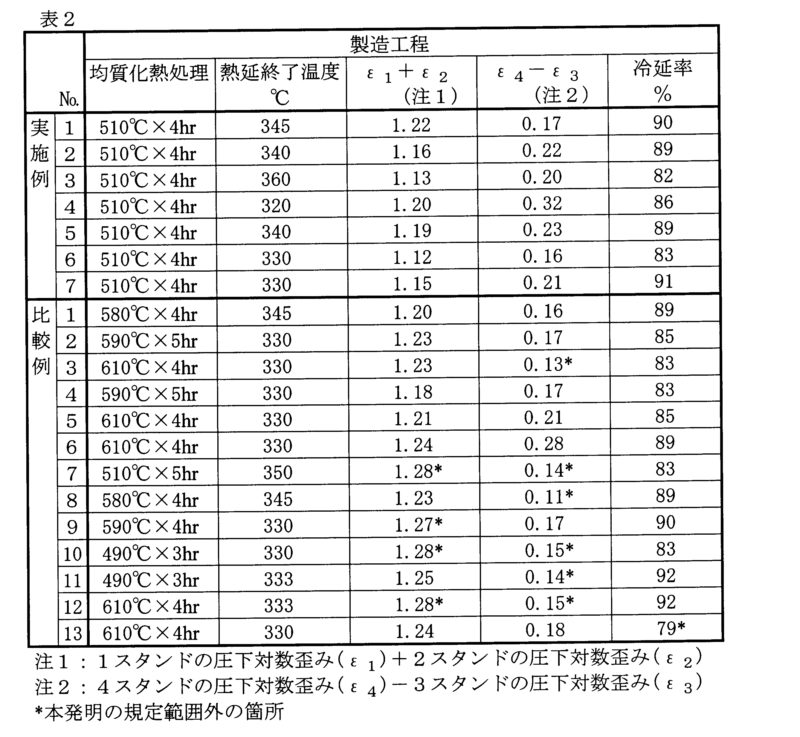
熱間圧延後の板(熱間圧延板)及び冷間圧延後の板(製品板)を供試材として、以下の測定試験を行った。その結果を表3に示す。
<再結晶率の測定>
各供試材(熱間圧延板)から試験片を切り出し、圧延方向に平行な断面が観察できるように研磨用樹脂に埋め込み、同断面を研磨して鏡面とし、次いでエッチングした後、倍率が100倍の光学顕微鏡により結晶組織を観察し、再結晶率を測定した。観察した断面は、各供試材において板幅方向中央部と両端部(端から20mmの位置)の3箇所とした。供試材の板厚をt、板厚方向に測定した再結晶組織の厚みをtr、同じく未再結晶部の厚みをtnとしたとき、t=tr+tnであり、再結晶率は(tr/t)×100で算出される値とした。再結晶組織は等軸粒からなり、未再結晶部は圧延方向に伸びた加工組織であり、両者は前記断面における結晶粒形状で区別できる。各供試材について、前記3箇所のうち最も低い再結晶率の値を、各供試材の再結晶率として表3に記載した。再結晶率の適正範囲は90%以上とした。熱間圧延板の再結晶率が90%以上であれば、製品板(負圧缶蓋用アルミニウム合金板)のリベット成形性に問題が生じない。表3において、再結晶率の欄の○印は再結晶率が90%以上、×印は90%未満を意味する。
<再結晶率の測定>
各供試材(熱間圧延板)から試験片を切り出し、圧延方向に平行な断面が観察できるように研磨用樹脂に埋め込み、同断面を研磨して鏡面とし、次いでエッチングした後、倍率が100倍の光学顕微鏡により結晶組織を観察し、再結晶率を測定した。観察した断面は、各供試材において板幅方向中央部と両端部(端から20mmの位置)の3箇所とした。供試材の板厚をt、板厚方向に測定した再結晶組織の厚みをtr、同じく未再結晶部の厚みをtnとしたとき、t=tr+tnであり、再結晶率は(tr/t)×100で算出される値とした。再結晶組織は等軸粒からなり、未再結晶部は圧延方向に伸びた加工組織であり、両者は前記断面における結晶粒形状で区別できる。各供試材について、前記3箇所のうち最も低い再結晶率の値を、各供試材の再結晶率として表3に記載した。再結晶率の適正範囲は90%以上とした。熱間圧延板の再結晶率が90%以上であれば、製品板(負圧缶蓋用アルミニウム合金板)のリベット成形性に問題が生じない。表3において、再結晶率の欄の○印は再結晶率が90%以上、×印は90%未満を意味する。
<集合組織の測定>
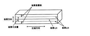
各供試材(熱間圧延板)から試験片を切り出し、圧延方向に平行な断面が観察できるように研磨用樹脂に埋め込み、同断面を研磨し鏡面とした。その後同断面にESCA(Electron Spectroscopy for Chemical Analysis)を用いてイオンエッチングを行い、圧延方向に平行な断面のcube方位面積率をEBSD(Electron Back Scattering Diffraction)法を用いて測定した。EBSD法による測定は、日本電子株式会社製、FE-SEM7000F走査型電子顕微鏡と株式会社TSLソリューションズ製、光検出器を用い、測定装置の加速電圧を20kVにて実施した。観察した断面は、各供試材において板幅方向中央部と、一方の端部(端から20mmの位置)とし、同断面における測定箇所は、図1に示すように、同断面を板厚方向に均等に4等分したときの板厚表層部(板表面から板厚の1/4厚さまでの領域)のどちらか一方とした。また、板幅方向中央部のcube方位面積率と板幅方向端部のcube方位面積率から、両者のcube方位面積率の差を算出した。このcube方位面積率の差が10%以下である場合、製品板の板幅方向の耳率差を1%以内とすることができる。ここで、cube方位とは、{100}面が板表面かつ、<001>方向が圧延方向に平行な結晶粒であり、cube方位の理想方位から傾角15°以内の粒をcube方位とし、cube方位面積率を算出した。
各供試材(熱間圧延板)から試験片を切り出し、圧延方向に平行な断面が観察できるように研磨用樹脂に埋め込み、同断面を研磨し鏡面とした。その後同断面にESCA(Electron Spectroscopy for Chemical Analysis)を用いてイオンエッチングを行い、圧延方向に平行な断面のcube方位面積率をEBSD(Electron Back Scattering Diffraction)法を用いて測定した。EBSD法による測定は、日本電子株式会社製、FE-SEM7000F走査型電子顕微鏡と株式会社TSLソリューションズ製、光検出器を用い、測定装置の加速電圧を20kVにて実施した。観察した断面は、各供試材において板幅方向中央部と、一方の端部(端から20mmの位置)とし、同断面における測定箇所は、図1に示すように、同断面を板厚方向に均等に4等分したときの板厚表層部(板表面から板厚の1/4厚さまでの領域)のどちらか一方とした。また、板幅方向中央部のcube方位面積率と板幅方向端部のcube方位面積率から、両者のcube方位面積率の差を算出した。このcube方位面積率の差が10%以下である場合、製品板の板幅方向の耳率差を1%以内とすることができる。ここで、cube方位とは、{100}面が板表面かつ、<001>方向が圧延方向に平行な結晶粒であり、cube方位の理想方位から傾角15°以内の粒をcube方位とし、cube方位面積率を算出した。
<結晶粒の縦横比の測定>
各供試材(製品板)から試験片を切り出し、表面を研磨して鏡面とし、次いで表面を電解エッチングし、光学顕微鏡により倍率100倍で結晶粒組織を観察及び写真撮影した。
この写真を用い、直線交切法によって圧延方向に対し直角方向の平均結晶粒径(平均結晶粒長さ)を測定した。具体的には、圧延方向に対して直角方向に、写真上の縮尺換算で0.3mm以上となる線分を引き、同線分により完全に切断される結晶粒の数を数え、その切断長さの平均値を求めた。写真上の場所を変えて同様の測定を繰り返し行い(計5回)、それぞれ切断長さの平均値を求めた。求めた5つの切断長さの平均値をさらに平均した値を、圧延方向に対し直角方向の平均結晶粒径(平均結晶粒幅)とした。また、前記写真を用い、圧延方向でも同様の測定を行い、圧延方向の平均結晶粒径(平均結晶粒長さ)を求めた。圧延方向の平均結晶粒径(平均結晶粒長さ)を、圧延方向に対し直角方向の平均結晶粒径(平均結晶粒幅)で除した値を、結晶粒の縦横比とした。
各供試材(製品板)から試験片を切り出し、表面を研磨して鏡面とし、次いで表面を電解エッチングし、光学顕微鏡により倍率100倍で結晶粒組織を観察及び写真撮影した。
この写真を用い、直線交切法によって圧延方向に対し直角方向の平均結晶粒径(平均結晶粒長さ)を測定した。具体的には、圧延方向に対して直角方向に、写真上の縮尺換算で0.3mm以上となる線分を引き、同線分により完全に切断される結晶粒の数を数え、その切断長さの平均値を求めた。写真上の場所を変えて同様の測定を繰り返し行い(計5回)、それぞれ切断長さの平均値を求めた。求めた5つの切断長さの平均値をさらに平均した値を、圧延方向に対し直角方向の平均結晶粒径(平均結晶粒幅)とした。また、前記写真を用い、圧延方向でも同様の測定を行い、圧延方向の平均結晶粒径(平均結晶粒長さ)を求めた。圧延方向の平均結晶粒径(平均結晶粒長さ)を、圧延方向に対し直角方向の平均結晶粒径(平均結晶粒幅)で除した値を、結晶粒の縦横比とした。
<0.2%耐力の測定>
各供試材(製品板)について、塗装・焼付け工程を模擬したオイルバスによる250℃×20秒の熱処理を施した後、引張方向が圧延方向と平行になるようにJIS-5号引張試験片を作製し、JISZ2241の規定に準じて引張試験を行い、0.2%耐力を求めた。0.2%耐力の適性範囲は250MPa以上とした。0.2%耐力が250MPa以上であれば、薄肉化された缶蓋であっても耐圧強度を満足する。リベット成形性の観点から、0.2%耐力は298MPa以下が好ましい。
各供試材(製品板)について、塗装・焼付け工程を模擬したオイルバスによる250℃×20秒の熱処理を施した後、引張方向が圧延方向と平行になるようにJIS-5号引張試験片を作製し、JISZ2241の規定に準じて引張試験を行い、0.2%耐力を求めた。0.2%耐力の適性範囲は250MPa以上とした。0.2%耐力が250MPa以上であれば、薄肉化された缶蓋であっても耐圧強度を満足する。リベット成形性の観点から、0.2%耐力は298MPa以下が好ましい。
<リベット成形性の測定>
各供試材(製品板)について、塗装・焼付け工程を模擬したオイルバスによる250℃×20秒の熱処理を施した後、各供試材から50mm×50mmの試験片を作製し、バブル工程を模擬した張出試験を実施し、限界張出し高さを求めた。張出試験は、図2に示すように、試験片1を上下のダイス2,3の間に挟み、一定のしわ押さえ力で固定し、ポンチ4を試験片1の中央部に対し垂直に押し込んで張出加工を行った。ダイス2,3は穴の内径が6.60mm、肩部半径が0.40mm、ポンチ4は外径が6.00mm、頭部の中央平坦部の直径が1mm、頭部の肩部半径が2.50mmである。
この張出試験により、試験片1に割れやくびれの発生なしに張出加工が行える張出高さの限界値(限界張出高さ)を測定した。限界張出高さの適正範囲は1.45mm以上とした。限界張出高さが1.45mm以上であれば、実成形時に十分な高さのボタンを成形することができ、リベット成形性に優れ、ステイク工程によってタブをしっかりと固定することができる。なお、タブの固定が不十分だと、開缶時にタブが取れて飲み口が開口しない不具合が発生する。
各供試材(製品板)について、塗装・焼付け工程を模擬したオイルバスによる250℃×20秒の熱処理を施した後、各供試材から50mm×50mmの試験片を作製し、バブル工程を模擬した張出試験を実施し、限界張出し高さを求めた。張出試験は、図2に示すように、試験片1を上下のダイス2,3の間に挟み、一定のしわ押さえ力で固定し、ポンチ4を試験片1の中央部に対し垂直に押し込んで張出加工を行った。ダイス2,3は穴の内径が6.60mm、肩部半径が0.40mm、ポンチ4は外径が6.00mm、頭部の中央平坦部の直径が1mm、頭部の肩部半径が2.50mmである。
この張出試験により、試験片1に割れやくびれの発生なしに張出加工が行える張出高さの限界値(限界張出高さ)を測定した。限界張出高さの適正範囲は1.45mm以上とした。限界張出高さが1.45mm以上であれば、実成形時に十分な高さのボタンを成形することができ、リベット成形性に優れ、ステイク工程によってタブをしっかりと固定することができる。なお、タブの固定が不十分だと、開缶時にタブが取れて飲み口が開口しない不具合が発生する。
<耳率差の測定>
各供試材(製品板)について、塗装・焼付け工程を模擬したオイルバスによる250℃×20秒の熱処理を施した後、板幅方向中央部と両端部(図3参照)から幅100mmの試験片を計3個切り出した。次いで、各試験片の中央部から直径66.7mmの円形ブランクを採取し、絞り比1.67で絞り成形して円筒容器を作成した。この円筒容器の側壁高さを、円筒容器底面の圧延方向を基準として、円周方向に45°ピッチで合計8点計測し、下記式2の計算式から耳率(re)を求めた。ただし、下記式2においてh45は前記圧延方向を基準とした45°方向4箇所の耳の平均高さ、h0,90は前記圧延方向を基準とした0°及び90°方向4箇所の耳の平均高さ、hav.は全測定点の平均高さを意味する。3個の試験片から得られた耳率(re)の値から、最大値と最小値の差(耳率差)を求めた。耳率差が1%以下の供試材を良、1%を超える供試材を不良と判定した。
re={(h45-h0,90)/hav.}×100(%)・・・(2)
各供試材(製品板)について、塗装・焼付け工程を模擬したオイルバスによる250℃×20秒の熱処理を施した後、板幅方向中央部と両端部(図3参照)から幅100mmの試験片を計3個切り出した。次いで、各試験片の中央部から直径66.7mmの円形ブランクを採取し、絞り比1.67で絞り成形して円筒容器を作成した。この円筒容器の側壁高さを、円筒容器底面の圧延方向を基準として、円周方向に45°ピッチで合計8点計測し、下記式2の計算式から耳率(re)を求めた。ただし、下記式2においてh45は前記圧延方向を基準とした45°方向4箇所の耳の平均高さ、h0,90は前記圧延方向を基準とした0°及び90°方向4箇所の耳の平均高さ、hav.は全測定点の平均高さを意味する。3個の試験片から得られた耳率(re)の値から、最大値と最小値の差(耳率差)を求めた。耳率差が1%以下の供試材を良、1%を超える供試材を不良と判定した。
re={(h45-h0,90)/hav.}×100(%)・・・(2)
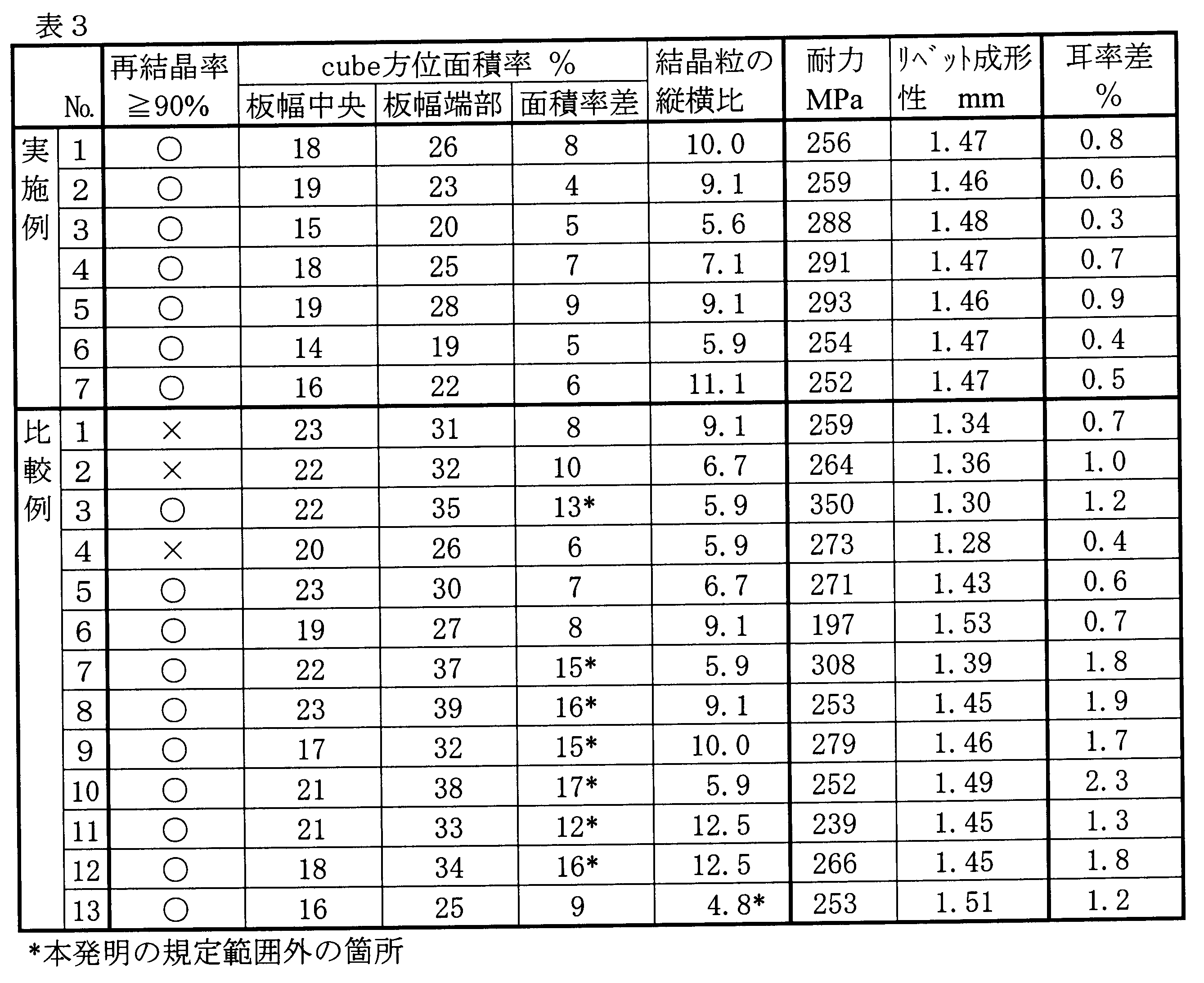
表3に示すように、アルミニウム合金板の組成、再結晶率、cube方位の面積率の差及び結晶粒の縦横比が本発明の規定を満たす実施例No.1~7は、製品板の強度が高く(250MPa以上)、リベット成形性が優れ(1.45mm以上の限界張出高さ)、板幅方向中央部と端部の耳率差が1%以下と小さい。
これに対し、比較例No.1は、Si含有量が過剰なため、熱間圧延板の再結晶率が低く、製品板のリベット成形性が劣る。
比較例No.2は、Fe含有量が少ないため、熱間圧延板の再結晶率が低く、製品板のリベット成形性が劣る。
比較例No.3は、Cu含有量が過剰なため、強度が高くなりすぎ、製品板のリベット成形性が劣る。また、比較例No.3は、4スタンド目の圧下対数歪みと3スタンドの目の圧下対数歪みの差(ε4-ε3)が小さいため、熱間圧延板のcube方位の面積率差が大きく、製品板の耳率差が大きくなった。
これに対し、比較例No.1は、Si含有量が過剰なため、熱間圧延板の再結晶率が低く、製品板のリベット成形性が劣る。
比較例No.2は、Fe含有量が少ないため、熱間圧延板の再結晶率が低く、製品板のリベット成形性が劣る。
比較例No.3は、Cu含有量が過剰なため、強度が高くなりすぎ、製品板のリベット成形性が劣る。また、比較例No.3は、4スタンド目の圧下対数歪みと3スタンドの目の圧下対数歪みの差(ε4-ε3)が小さいため、熱間圧延板のcube方位の面積率差が大きく、製品板の耳率差が大きくなった。
比較例No.4は、Mn含有量が少ないため、熱間圧延板の再結晶率が低く、製品板のリベット成形性が劣る。
比較例No.5は、Mn含有量が過剰なため、製品板のリベット成形性が劣る。
比較例No.6は、Mg含有量が少ないため、製品板の強度が低い。
比較例No.7は、Mg含有量が過剰なため、製品板の強度が高くなりすぎ、リベット成形性が劣る。また、比較例No.7は、1スタンド目及び2スタンド目の圧下対数歪みの合計(ε1+ε2)が大き過ぎ、かつ4スタンド目の圧下対数歪みと3スタンドの目の圧下対数歪みの差(ε4-ε3)が小さ過ぎたため、熱間圧延板のcube方位の面積率差が大きく、製品板の耳率差が大きくなった。
比較例No.5は、Mn含有量が過剰なため、製品板のリベット成形性が劣る。
比較例No.6は、Mg含有量が少ないため、製品板の強度が低い。
比較例No.7は、Mg含有量が過剰なため、製品板の強度が高くなりすぎ、リベット成形性が劣る。また、比較例No.7は、1スタンド目及び2スタンド目の圧下対数歪みの合計(ε1+ε2)が大き過ぎ、かつ4スタンド目の圧下対数歪みと3スタンドの目の圧下対数歪みの差(ε4-ε3)が小さ過ぎたため、熱間圧延板のcube方位の面積率差が大きく、製品板の耳率差が大きくなった。
比較例8~12は、1スタンド目及び2スタンド目の圧下対数歪みの合計(ε1+ε2が大き過ぎ、又は/及び4スタンド目の圧下対数歪みと3スタンドの目の圧下対数歪みの差(ε4-ε3)が小さ過ぎた。このため、比較例8~12はいずれも熱間圧延板のcube方位の面積率差が大きく、製品板の耳率差が大きくなった。
比較例13は、冷間圧延率が低いため、結晶粒径の縦横比が小さく、加工組織の発達が不十分となり、製品板の耳率差が大きくなった。
比較例13は、冷間圧延率が低いため、結晶粒径の縦横比が小さく、加工組織の発達が不十分となり、製品板の耳率差が大きくなった。
本発明を詳細にまた特定の実施態様を参照して説明したが、本発明の精神と範囲を逸脱することなく様々な変更や修正を加えることができることは当業者にとって明らかである。
本出願は、2015年3月4日出願の日本特許出願(特願2015-042375)に基づくものであり、その内容はここに参照として取り込まれる。
本出願は、2015年3月4日出願の日本特許出願(特願2015-042375)に基づくものであり、その内容はここに参照として取り込まれる。
本発明の負圧缶蓋用アルミニウム合金板は、材料強度が高く、必要な耐圧強度が得られ、リベット成形性にも優れており、板幅方向に耳率差を小さくでき、2ピースタイプのアルミニウム缶として有用である。
1 試験片
2,3 ダイス
4 ポンチ
2,3 ダイス
4 ポンチ
Claims (2)
- Si:0.05質量%以上、0.40%質量以下、Fe:0.10質量%以上、0.50質量%以下、Mn:0.10質量%以上、0.80質量%未満、Mg:1.0質量%以上、3.5質量%以下を含有し、残部Al及び不可避不純物からなり、熱間圧延後の板の再結晶率が90%以上、かつ板幅方向の中央部と端部において圧延方向に平行な断面の板表面から板厚の1/4厚さまでの集合組織を測定した場合に、前記中央部のcube方位面積率と端部におけるcube方位の面積率との差が10%以下であり、冷間圧延後の板の表面の結晶粒の縦横比が5以上であることを特徴とする負圧缶蓋用アルミニウム合金板。
- 合金成分として、さらにCu:0.40%以下を含有することを特徴とした請求項1に記載された負圧缶蓋用アルミニウム合金板。
Priority Applications (2)
| Application Number | Priority Date | Filing Date | Title |
|---|---|---|---|
| CN201680013102.4A CN107406923A (zh) | 2015-03-04 | 2016-02-16 | 负压罐盖用铝合金板 |
| KR1020177024487A KR20170110123A (ko) | 2015-03-04 | 2016-02-16 | 부압 캔 캡용 알루미늄 합금판 |
Applications Claiming Priority (2)
| Application Number | Priority Date | Filing Date | Title |
|---|---|---|---|
| JP2015042375A JP6058050B2 (ja) | 2015-03-04 | 2015-03-04 | 負圧缶蓋用アルミニウム合金板 |
| JP2015-042375 | 2015-03-04 |
Publications (1)
| Publication Number | Publication Date |
|---|---|
| WO2016140054A1 true WO2016140054A1 (ja) | 2016-09-09 |
Family
ID=56844762
Family Applications (1)
| Application Number | Title | Priority Date | Filing Date |
|---|---|---|---|
| PCT/JP2016/054429 Ceased WO2016140054A1 (ja) | 2015-03-04 | 2016-02-16 | 負圧缶蓋用アルミニウム合金板 |
Country Status (4)
| Country | Link |
|---|---|
| JP (1) | JP6058050B2 (ja) |
| KR (1) | KR20170110123A (ja) |
| CN (1) | CN107406923A (ja) |
| WO (1) | WO2016140054A1 (ja) |
Cited By (3)
| Publication number | Priority date | Publication date | Assignee | Title |
|---|---|---|---|---|
| CN111372770A (zh) * | 2017-10-30 | 2020-07-03 | 日本制铁株式会社 | 复合板 |
| WO2021211696A1 (en) | 2020-04-15 | 2021-10-21 | Novelis Inc. | Aluminum alloys produced from recycled aluminum alloy scrap |
| WO2025010263A1 (en) * | 2023-07-03 | 2025-01-09 | Novelis Inc. | Methods of producing 6xxx series aluminum alloys at thin gauge |
Families Citing this family (10)
| Publication number | Priority date | Publication date | Assignee | Title |
|---|---|---|---|---|
| CN108385002A (zh) * | 2018-04-18 | 2018-08-10 | 中铝瑞闽股份有限公司 | 一种铝瓶螺旋盖铝合金带材及其制备方法 |
| KR102559606B1 (ko) * | 2018-08-31 | 2023-07-24 | 가부시키가이샤 유에이씨제이 | 알루미늄 합금판 |
| JP7661118B2 (ja) * | 2021-05-12 | 2025-04-14 | 株式会社Uacj | リングプル型キャップ用のアルミニウム合金板およびその製造方法 |
| JP7652730B2 (ja) | 2022-03-09 | 2025-03-27 | 株式会社Uacj | 缶蓋用アルミニウム合金板 |
| JP7473708B1 (ja) | 2023-04-17 | 2024-04-23 | 株式会社Uacj | 缶蓋用アルミニウム合金板 |
| JP7420994B1 (ja) | 2023-04-17 | 2024-01-23 | 株式会社Uacj | 缶蓋用アルミニウム合金板の製造方法 |
| JP7420996B1 (ja) | 2023-04-17 | 2024-01-23 | 株式会社Uacj | 缶蓋用アルミニウム合金板 |
| JP7473707B1 (ja) | 2023-04-17 | 2024-04-23 | 株式会社Uacj | 缶蓋用アルミニウム合金板 |
| JP7420995B1 (ja) | 2023-04-17 | 2024-01-23 | 株式会社Uacj | 缶蓋用アルミニウム合金板 |
| WO2025142252A1 (ja) | 2023-12-28 | 2025-07-03 | 株式会社Uacj | 未塗装の缶蓋用アルミニウム合金板 |
Citations (6)
| Publication number | Priority date | Publication date | Assignee | Title |
|---|---|---|---|---|
| JP2001214248A (ja) * | 2000-01-28 | 2001-08-07 | Sky Alum Co Ltd | 缶蓋用アルミニウム合金硬質板の製造方法 |
| JP2004339604A (ja) * | 2003-04-25 | 2004-12-02 | Sumitomo Light Metal Ind Ltd | 異方性に優れた缶エンド用アルミニウム合金板およびその製造方法 |
| JP2005226120A (ja) * | 2004-02-12 | 2005-08-25 | Kobe Steel Ltd | 包装容器エンド用アルミニウム合金板およびその製造方法 |
| JP2006257470A (ja) * | 2005-03-16 | 2006-09-28 | Furukawa Sky Kk | 缶蓋用アルミニウム合金板の製造方法 |
| JP2007131920A (ja) * | 2005-11-11 | 2007-05-31 | Furukawa Sky Kk | 耳率が小さく且つ板幅方向の耳率が安定した缶蓋用アルミニウム合金板およびその製造方法 |
| JP2013023757A (ja) * | 2011-07-25 | 2013-02-04 | Sumitomo Light Metal Ind Ltd | 負圧缶蓋用アルミニウム合金板及びその製造方法 |
Family Cites Families (3)
| Publication number | Priority date | Publication date | Assignee | Title |
|---|---|---|---|---|
| JP4077997B2 (ja) * | 1999-09-03 | 2008-04-23 | 古河スカイ株式会社 | 缶蓋用アルミニウム合金硬質板の製造方法 |
| JP4019082B2 (ja) * | 2005-03-25 | 2007-12-05 | 株式会社神戸製鋼所 | 高温特性に優れたボトル缶用アルミニウム合金板 |
| CN103014445B (zh) * | 2012-12-27 | 2014-11-26 | 亚洲铝业(中国)有限公司 | 5052铝合金罐盖料基材及其生产方法 |
-
2015
- 2015-03-04 JP JP2015042375A patent/JP6058050B2/ja not_active Expired - Fee Related
-
2016
- 2016-02-16 CN CN201680013102.4A patent/CN107406923A/zh active Pending
- 2016-02-16 WO PCT/JP2016/054429 patent/WO2016140054A1/ja not_active Ceased
- 2016-02-16 KR KR1020177024487A patent/KR20170110123A/ko not_active Abandoned
Patent Citations (6)
| Publication number | Priority date | Publication date | Assignee | Title |
|---|---|---|---|---|
| JP2001214248A (ja) * | 2000-01-28 | 2001-08-07 | Sky Alum Co Ltd | 缶蓋用アルミニウム合金硬質板の製造方法 |
| JP2004339604A (ja) * | 2003-04-25 | 2004-12-02 | Sumitomo Light Metal Ind Ltd | 異方性に優れた缶エンド用アルミニウム合金板およびその製造方法 |
| JP2005226120A (ja) * | 2004-02-12 | 2005-08-25 | Kobe Steel Ltd | 包装容器エンド用アルミニウム合金板およびその製造方法 |
| JP2006257470A (ja) * | 2005-03-16 | 2006-09-28 | Furukawa Sky Kk | 缶蓋用アルミニウム合金板の製造方法 |
| JP2007131920A (ja) * | 2005-11-11 | 2007-05-31 | Furukawa Sky Kk | 耳率が小さく且つ板幅方向の耳率が安定した缶蓋用アルミニウム合金板およびその製造方法 |
| JP2013023757A (ja) * | 2011-07-25 | 2013-02-04 | Sumitomo Light Metal Ind Ltd | 負圧缶蓋用アルミニウム合金板及びその製造方法 |
Cited By (5)
| Publication number | Priority date | Publication date | Assignee | Title |
|---|---|---|---|---|
| CN111372770A (zh) * | 2017-10-30 | 2020-07-03 | 日本制铁株式会社 | 复合板 |
| CN111372770B (zh) * | 2017-10-30 | 2021-10-26 | 日本制铁株式会社 | 复合板 |
| WO2021211696A1 (en) | 2020-04-15 | 2021-10-21 | Novelis Inc. | Aluminum alloys produced from recycled aluminum alloy scrap |
| EP4136269A1 (en) * | 2020-04-15 | 2023-02-22 | Novelis, Inc. | Aluminum alloys produced from recycled aluminum alloy scrap |
| WO2025010263A1 (en) * | 2023-07-03 | 2025-01-09 | Novelis Inc. | Methods of producing 6xxx series aluminum alloys at thin gauge |
Also Published As
| Publication number | Publication date |
|---|---|
| CN107406923A (zh) | 2017-11-28 |
| KR20170110123A (ko) | 2017-10-10 |
| JP2016160511A (ja) | 2016-09-05 |
| JP6058050B2 (ja) | 2017-01-11 |
Similar Documents
| Publication | Publication Date | Title |
|---|---|---|
| JP6058050B2 (ja) | 負圧缶蓋用アルミニウム合金板 | |
| JP5432642B2 (ja) | 缶エンド用アルミニウム合金板及びその製造方法。 | |
| JP2009221567A (ja) | 陽圧塗装缶蓋用アルミニウム合金板およびその製造方法 | |
| JP6336434B2 (ja) | 缶ボディ用アルミニウム合金板及びその製造方法 | |
| JP6912886B2 (ja) | 飲料缶胴用アルミニウム合金板及びその製造方法 | |
| JP7138396B2 (ja) | 缶胴体用アルミニウム合金板及びその製造方法 | |
| JP2016141886A (ja) | 缶蓋用アルミニウム合金板 | |
| JP2016079501A (ja) | 缶蓋用アルミニウム合金板 | |
| JP4460406B2 (ja) | ボトル缶用アルミニウム合金板及びその製造方法 | |
| JP6435268B2 (ja) | 缶エンド用アルミニウム合金板及びその製造方法 | |
| JP2016079502A (ja) | 缶蓋用アルミニウム合金板 | |
| KR20210040127A (ko) | 알루미늄 합금판 | |
| JP5699192B2 (ja) | 負圧缶蓋用アルミニウム合金板 | |
| JP3871473B2 (ja) | 缶胴用アルミニウム合金板の製造方法 | |
| JP4771726B2 (ja) | 飲料缶胴用アルミニウム合金板およびその製造方法 | |
| JP2006257470A (ja) | 缶蓋用アルミニウム合金板の製造方法 | |
| WO2016063876A1 (ja) | 缶蓋用アルミニウム合金板 | |
| JP2006283113A (ja) | 飲料缶胴用アルミニウム合金板およびその製造方法 | |
| JP4250030B2 (ja) | 光輝性ホイールリム用アルミニウム合金板およびその製造方法 | |
| JP4467443B2 (ja) | アルミニウム合金板の製造方法 | |
| JP6033192B2 (ja) | 負圧缶蓋用アルミニウム合金板 | |
| JP2007051307A (ja) | ボトムしわ性が良好なキャンボディ用アルミニウム合金板およびその製造方法 | |
| JP4392263B2 (ja) | 包装容器エンド用アルミニウム合金板およびその製造方法 | |
| JP2000096171A (ja) | 高強度、低耳率キャップ用Al合金板及びその製造方法 | |
| JP2011080155A (ja) | ボトムしわ性が良好なキャンボディ用アルミニウム合金板 |
Legal Events
| Date | Code | Title | Description |
|---|---|---|---|
| 121 | Ep: the epo has been informed by wipo that ep was designated in this application |
Ref document number: 16758748 Country of ref document: EP Kind code of ref document: A1 |
|
| ENP | Entry into the national phase |
Ref document number: 20177024487 Country of ref document: KR Kind code of ref document: A |
|
| NENP | Non-entry into the national phase |
Ref country code: DE |
|
| 122 | Ep: pct application non-entry in european phase |
Ref document number: 16758748 Country of ref document: EP Kind code of ref document: A1 |