WO2016136572A1 - ヘッドアップディスプレイ装置 - Google Patents
ヘッドアップディスプレイ装置 Download PDFInfo
- Publication number
- WO2016136572A1 WO2016136572A1 PCT/JP2016/054662 JP2016054662W WO2016136572A1 WO 2016136572 A1 WO2016136572 A1 WO 2016136572A1 JP 2016054662 W JP2016054662 W JP 2016054662W WO 2016136572 A1 WO2016136572 A1 WO 2016136572A1
- Authority
- WO
- WIPO (PCT)
- Prior art keywords
- backlight
- display device
- head
- display
- control board
- Prior art date
- Legal status (The legal status is an assumption and is not a legal conclusion. Google has not performed a legal analysis and makes no representation as to the accuracy of the status listed.)
- Ceased
Links
Images



Classifications
-
- B—PERFORMING OPERATIONS; TRANSPORTING
- B60—VEHICLES IN GENERAL
- B60K—ARRANGEMENT OR MOUNTING OF PROPULSION UNITS OR OF TRANSMISSIONS IN VEHICLES; ARRANGEMENT OR MOUNTING OF PLURAL DIVERSE PRIME-MOVERS IN VEHICLES; AUXILIARY DRIVES FOR VEHICLES; INSTRUMENTATION OR DASHBOARDS FOR VEHICLES; ARRANGEMENTS IN CONNECTION WITH COOLING, AIR INTAKE, GAS EXHAUST OR FUEL SUPPLY OF PROPULSION UNITS IN VEHICLES
- B60K35/00—Instruments specially adapted for vehicles; Arrangement of instruments in or on vehicles
- B60K35/20—Output arrangements, i.e. from vehicle to user, associated with vehicle functions or specially adapted therefor
- B60K35/21—Output arrangements, i.e. from vehicle to user, associated with vehicle functions or specially adapted therefor using visual output, e.g. blinking lights or matrix displays
- B60K35/23—Head-up displays [HUD]
- B60K35/231—Head-up displays [HUD] characterised by their arrangement or structure for integration into vehicles
-
- B—PERFORMING OPERATIONS; TRANSPORTING
- B60—VEHICLES IN GENERAL
- B60K—ARRANGEMENT OR MOUNTING OF PROPULSION UNITS OR OF TRANSMISSIONS IN VEHICLES; ARRANGEMENT OR MOUNTING OF PLURAL DIVERSE PRIME-MOVERS IN VEHICLES; AUXILIARY DRIVES FOR VEHICLES; INSTRUMENTATION OR DASHBOARDS FOR VEHICLES; ARRANGEMENTS IN CONNECTION WITH COOLING, AIR INTAKE, GAS EXHAUST OR FUEL SUPPLY OF PROPULSION UNITS IN VEHICLES
- B60K35/00—Instruments specially adapted for vehicles; Arrangement of instruments in or on vehicles
- B60K35/20—Output arrangements, i.e. from vehicle to user, associated with vehicle functions or specially adapted therefor
- B60K35/28—Output arrangements, i.e. from vehicle to user, associated with vehicle functions or specially adapted therefor characterised by the type of the output information, e.g. video entertainment or vehicle dynamics information; characterised by the purpose of the output information, e.g. for attracting the attention of the driver
-
- B—PERFORMING OPERATIONS; TRANSPORTING
- B60—VEHICLES IN GENERAL
- B60K—ARRANGEMENT OR MOUNTING OF PROPULSION UNITS OR OF TRANSMISSIONS IN VEHICLES; ARRANGEMENT OR MOUNTING OF PLURAL DIVERSE PRIME-MOVERS IN VEHICLES; AUXILIARY DRIVES FOR VEHICLES; INSTRUMENTATION OR DASHBOARDS FOR VEHICLES; ARRANGEMENTS IN CONNECTION WITH COOLING, AIR INTAKE, GAS EXHAUST OR FUEL SUPPLY OF PROPULSION UNITS IN VEHICLES
- B60K35/00—Instruments specially adapted for vehicles; Arrangement of instruments in or on vehicles
- B60K35/60—Instruments characterised by their location or relative disposition in or on vehicles
-
- B—PERFORMING OPERATIONS; TRANSPORTING
- B60—VEHICLES IN GENERAL
- B60K—ARRANGEMENT OR MOUNTING OF PROPULSION UNITS OR OF TRANSMISSIONS IN VEHICLES; ARRANGEMENT OR MOUNTING OF PLURAL DIVERSE PRIME-MOVERS IN VEHICLES; AUXILIARY DRIVES FOR VEHICLES; INSTRUMENTATION OR DASHBOARDS FOR VEHICLES; ARRANGEMENTS IN CONNECTION WITH COOLING, AIR INTAKE, GAS EXHAUST OR FUEL SUPPLY OF PROPULSION UNITS IN VEHICLES
- B60K35/00—Instruments specially adapted for vehicles; Arrangement of instruments in or on vehicles
- B60K35/80—Arrangements for controlling instruments
-
- B—PERFORMING OPERATIONS; TRANSPORTING
- B60—VEHICLES IN GENERAL
- B60R—VEHICLES, VEHICLE FITTINGS, OR VEHICLE PARTS, NOT OTHERWISE PROVIDED FOR
- B60R11/00—Arrangements for holding or mounting articles, not otherwise provided for
- B60R11/02—Arrangements for holding or mounting articles, not otherwise provided for for radio sets, television sets, telephones, or the like; Arrangement of controls thereof
Definitions
- the present invention relates to a head-up display device disposed on an upper part of a meter unit.
- a head-up display device is used to provide road guidance to the driver of the vehicle.
- information from the head-up display device is displayed above a meter unit in which instruments are accommodated so that the amount of movement of the driver's line of sight is small.
- the driver can drive while referring to the information displayed above the meter unit.
- Patent Document 1 As a conventional technique related to such a head-up display device, there is a technique disclosed in Patent Document 1.
- FIG. 3 of Patent Document 1 discloses that a unitized head-up display device is attached to an upper portion of a meter unit.
- the space that can be used for mounting the head-up display device is limited. Miniaturization of the head-up display device is desired.
- This invention makes it a subject to miniaturize the head-up display apparatus attached to the upper part of a meter unit.
- a head-up display device in which a display device for displaying information and a backlight for illuminating the display device are arranged at the upper part of the meter unit.
- the meter unit contains a control board for controlling the display and the backlight
- a head-up display device comprising: a first wiring portion that connects the control board to the backlight; and a second wiring portion that connects the backlight to the display.
- the backlight is supported by a backlight substrate, On one surface of the backlight substrate, a heat radiating plate for radiating heat generated in the backlight is provided, The first wiring part and the second wiring part are connected to a surface of the backlight substrate opposite to the side where the heat sink is provided.
- the first wiring portion is located below the backlight
- the second wiring part is located above the backlight
- the display unit and the control board for controlling the backlight are accommodated in the meter unit. That is, some of the components of the head-up display device were stored in the meter unit. Thereby, size reduction of a head-up display apparatus can be achieved.
- the head-up display device has a first wiring portion that connects the control board to the backlight, and a second wiring portion that connects the backlight to the display.
- the display is connected to the control board via the backlight.
- the head-up display device is unitized and attached to the upper portion of the meter unit. If the first wiring part and the second wiring part are attached to the control board at the time of attachment, the attachment work to the meter unit may take a long time. By connecting the second wiring unit from the backlight to the display, only the first wiring unit needs to be connected to the control board when the meter unit is attached. The meter unit can be easily attached. Further, by reducing the number of wirings exposed to the outside, the head-up display device can be easily transported.
- the first wiring portion and the second wiring portion are connected to the surface of the backlight substrate opposite to the side where the heat sink is provided.
- a heat sink can be attached to the whole surface of the backlight substrate. A large heat radiation area can be secured, and heat can be radiated more efficiently.
- the first wiring portion is located below the backlight.
- the meter unit and the control board are provided below the backlight. By positioning the first wiring portion below the backlight, the overall length of the first wiring portion can be shortened.
- FIG. 1 is a view showing a vehicle equipped with a head-up display device according to an embodiment of the present invention.
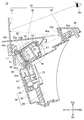
- FIG. 2 is a sectional view taken along line 2-2 of FIG.
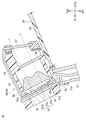
- FIG. 3 is a three-part enlarged view of FIG. 2.
- FIG. 3 is a front view of the backlight shown in FIG. 2. It is a disassembled perspective view explaining the effect
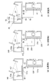
- FIG. 3 is a diagram comparing the head-up display device according to the embodiment shown in FIG. 2 and the head-up display device according to a comparative example.
- left and right refer to the left and right based on the vehicle occupant
- front and rear refer to the front and rear based on the traveling direction of the vehicle.
- Fr indicates the front
- Rr indicates the rear
- Le indicates the left when viewed from the occupant
- Ri indicates the right when viewed from the occupant
- Up indicates the upper side
- Dn indicates the lower side.
- a head-up display device according to an embodiment of the present invention will be described taking a case where it is mounted on a vehicle as an example.
- the vehicle 10 is a right-hand drive vehicle and is shown in a state in which the front is viewed from the driver's seat. For convenience of explanation, the vehicle 10 is shown with the steering wheel removed.
- the instrument panel 11 extends in the vehicle width direction in front of the driver's seat, and the meter unit 20 is attached to the instrument panel 11.
- the meter unit 20 includes a speedometer 30, a tachometer 22, a fuel meter 23, and an odometer 24.
- a windshield 15 is provided in front of the meter unit 20.
- a head-up display device 40 is attached to the upper part of the meter unit 20.
- the speedometer 30 includes a control board 31 housed in the housing 25 of the meter unit 20, a motor 32 provided in front of the control board 31 and controlled by the control board 31, and a tip of the motor 32. And an attached pointer 33.
- the motor 32 is provided on the front side
- the pointer 33 is provided on the rear side.
- the head-up display device 40 includes a display unit 50 attached to the upper portion of the housing 25 of the meter unit 20, a mirror unit 42 that is disposed behind the display unit 50 and reflects light from the display unit 50 forward, A projection surface portion 43 that is provided on the upper portion of the display unit 50 so as to be swingable and onto which the light reflected by the mirror unit 42 is projected, and a cover that passes through the projection surface portion 43 and covers the display unit 50 and the mirror unit 42. 44.
- the display unit 50, the mirror unit 42, the projection surface 43, and the cover 44 are sub-assembled and integrated. That is, the integrated display unit 50, mirror unit 42, projection surface portion 43, and cover 44 are attached to the upper portion of the meter unit 20.
- the display unit 50 includes a stay 51 attached to the housing 25, a heat sink 52 attached to the rear portion of the stay 51, a backlight unit 53 attached to the rear surface of the heat sink 52, and the backlight unit.
- a light box 54 disposed at the rear of 53 and attached to the stay 51; a condenser lens 55 and a lenticular lens 56 which are supported by the light box 54 and transmit light emitted from the backlight unit 53; And a display 57 for displaying information to be projected and projected onto the projection surface 43 (see FIG. 2).
- the backlight unit 53 includes six backlights 53b made of LEDs or the like mounted on a backlight substrate 53a.
- a first wiring part 58 is connected from the upper end of the control board 31 to the lower part of the rear surface of the backlight board 53a. Further, a second wiring portion 59 is connected from the upper rear surface of the backlight substrate 53a to the display 57.
- the first wiring unit 58 and the second wiring unit 59 employ flexible wiring such as FPC (FlexibleFlexPrinted Circuit) and FFC (Flexible Flat Cable).
- the first wiring part 58 and the second wiring part 59 are detachably provided to the backlight substrate 53a via connectors 53c and 53d. These connectors 53c and 53d are provided on the same surface on which the backlight 53b of the backlight substrate 53a is mounted.
- the control board 31 housed in the meter unit 20 controls the blinking of the backlight 53b and the display information on the display 57.
- the control board 31 is a control unit for the meter unit 20, and also serves as a control unit for the backlight 53 b and the display device 57.
- a connector 31 a for connecting the first wiring part 58 is provided on the upper part of the front surface of the control board 31.
- the mirror unit 42 includes a mirror holder 42a attached to the upper portion of the housing 25 of the meter unit 20, and a mirror 42b held by the mirror holder 42a.
- the projection surface portion 43 includes a combiner holder 43a that is supported by the stay 51 so as to be swingable, and a combiner 43b that is held by the combiner holder 43a and projects light.
- an arrow for prompting a right turn is displayed on the display device 57.
- the light from the backlight 53b illuminates the display 57.
- the light that has passed through the display device 57 is reflected forward by the mirror 42b, passes through the opening 44a of the cover 44, and is projected onto the combiner 43b.
- the driver Mn recognizes that it is time to turn right by visually recognizing the virtual image of the right-pointing arrow projected on the combiner 43b.
- the heat generated when the backlight 53b is lit is released from the heat sink 52 in contact with the front surface of the backlight substrate 53a.
- the stay 51 is formed with a stay opening 51 a for exposing the heat radiating plate 52.
- the stay 51 and the heat radiating plate 52 can be integrally formed of a member having high thermal conductivity such as aluminum.
- the heat capacity can be increased to improve heat dissipation.
- a heat conductive sheet can be provided between the heat dissipation plate 52 and the backlight substrate 53a. In this case, the heat of the backlight 53b can be radiated efficiently.
- the head-up display device 40 is attached to the meter unit 20 after being unitized except for the control board 31 (see FIG. 2) housed in the meter unit 20. Specifically, the stay 51 is fixed to the housing 25 by bolts 61 and 61, and the first wiring portion 58 is connected to the control board 31 (see FIG. 2).
- FIG. 6A shows a head-up display device 140 according to Comparative Example 1.
- the head-up display device 140 has a control board 131b different from the control board 131a of the meter unit 120.
- a backlight 153b and a display unit 157 are connected to the control board 131b.
- the control substrate 131b is included in the head-up display device 140, the number of parts increases and the device is enlarged.
- FIG. 6B shows a head-up display device 240 according to Comparative Example 2.
- a control board 231 for controlling the backlight 253b and the display unit 257 is housed in the meter unit 220.
- the number of components can be reduced and the device can be downsized (see ⁇ ) as compared with the head-up display device 240 according to the comparative example 1.
- the head-up display device 240 when the head-up display device 240 is attached to the meter unit 220, it is necessary to connect the first wiring part 258 and the second wiring part 259 to the control board 231, and the attachment work takes time.
- FIG. 6C shows a head-up display device 40 according to the embodiment.
- the display 57 and the control board 31 for controlling the backlight 53b are accommodated in the meter unit 20. That is, some of the components of the head-up display device 40 are accommodated in the meter unit 20. Thereby, reduction of the number of parts of the head-up display device 40 and size reduction can be achieved.
- the display device 57 is connected to the control board 31 through the backlight 53b.
- the head-up display device 40 is unitized and attached to the upper part of the meter unit 20. If the first wiring part 58 and the second wiring part 59 are each attached to the control board 31 during attachment, the attachment work to the meter unit 20 may take a long time. By connecting the second wiring portion 59 from the backlight 53b to the display device 57, only the first wiring portion 58 may be connected to the control board 31 when the meter unit 20 is attached. The work of attaching the meter unit 20 can be easily performed. Further, by reducing the wiring exposed to the outside, the head-up display device 40 can be easily transported.
- the first wiring portion 58 and the second wiring portion 59 are connected to the surface of the backlight substrate 53a opposite to the side where the heat sink 52 is in contact. .
- the heat sink 52 can be attached to the entire surface of the backlight substrate 53a. A large heat radiation area can be secured, and heat can be radiated more efficiently.
- the first wiring part 58 is located below the backlight 53b.
- the meter unit 20 and the control board 31 are provided below the backlight 53b. By positioning the first wiring part 58 below the backlight 53b, the entire length of the first wiring part 58 can be shortened.
- the backlight substrate 53a is arranged so that at least a part thereof is in contact with an extension line L1 obtained by extending the control substrate 31 upward. By disposing the backlight substrate 53a in the vicinity of the control substrate 31, the overall length of the first wiring portion 58 can be shortened.
- control board 31 is integral with the control board 31 for controlling the speedometer 30 (instrument 30) housed in the meter unit 20. As a result, the number of parts can be further reduced.
- control board 31 is located above the motor 32 for operating the pointer 33 of the speedometer 30.
- control board 31 can be arranged at a higher position of the meter unit 20.
- positioned at the upper part of the meter unit 20 can be shortened, and the 1st wiring part 58 can be shortened further.
- the head-up display device according to the present invention has been described based on an example mounted on a vehicle, the head-up display device can also be applied to vehicles, work machines, construction machines, and the like other than vehicles. Furthermore, the head-up display device according to the present invention is not limited to the projection surface unit integrated type, but can be applied to a type that projects onto the windshield. Furthermore, as the information projected on the projection surface portion, arbitrary information can be selected in addition to the road guidance.
- the present invention is not limited to the examples as long as the operations and effects of the present invention are exhibited.
- the head-up display device of the present invention is suitable for a vehicle.
Landscapes
- Engineering & Computer Science (AREA)
- Mechanical Engineering (AREA)
- Chemical & Material Sciences (AREA)
- Combustion & Propulsion (AREA)
- Transportation (AREA)
- Instrument Panels (AREA)
- Fittings On The Vehicle Exterior For Carrying Loads, And Devices For Holding Or Mounting Articles (AREA)
Abstract
メータユニットの上部に取り付けられるヘッドアップディスプレイ装置を小型化すること。 ヘッドアップディスプレイ装置(40)は、情報が表示される表示器(57)と、この表示器(57)を照射するバックライト(53b)と、がメータユニット(20)の上部に配置されてなる。メータユニット(20)には、表示器(57)、及び、バックライト(53b)を制御するための制御基板(31)が収納されている。制御基板(31)からバックライト(53b)までを繋ぐ第1配線部(58)と、バックライト(53b)から表示器(57)までを繋ぐ第2配線部(59)と、を有している。
Description
本発明は、メータユニットの上部に配置されたヘッドアップディスプレイ装置に関する。
例えば、車両の運転者に道路案内をするために、ヘッドアップディスプレイ装置が用いられる。ヘッドアップディスプレイ装置からの情報は、運転者の視線の移動量が少なくて済むよう、計器類が収納されたメータユニットの上方に表示されることが一般的である。運転者は、メータユニットの上方に表示された情報を参照しながら運転を行うことができる。このようなヘッドアップディスプレイ装置に関する従来技術として特許文献1に開示される技術がある。
特許文献1の図3には、ユニット化されたヘッドアップディスプレイ装置を、メータユニットの上部に取り付けることが開示されている。
ここで、メータユニットの上部のうち、ヘッドアップディスプレイ装置の取り付けに用いることができるスペースは限られている。ヘッドアップディスプレイ装置の小型化が望まれる。
本発明は、メータユニットの上部に取り付けられるヘッドアップディスプレイ装置の小型化を課題とする。
請求項1による発明によれば、情報が表示される表示器と、この表示器を照射するバックライトと、がメータユニットの上部に配置されたヘッドアップディスプレイ装置において、
前記メータユニットには、前記表示器、及び、前記バックライトを制御するための制御基板が収納され、
前記制御基板から前記バックライトまでを繋ぐ第1配線部と、前記バックライトから前記表示器までを繋ぐ第2配線部と、を有していることを特徴とするヘッドアップディスプレイ装置が提供される。
前記メータユニットには、前記表示器、及び、前記バックライトを制御するための制御基板が収納され、
前記制御基板から前記バックライトまでを繋ぐ第1配線部と、前記バックライトから前記表示器までを繋ぐ第2配線部と、を有していることを特徴とするヘッドアップディスプレイ装置が提供される。
請求項2に記載のごとく、好ましくは、前記バックライトは、バックライト基板によって支持され、
このバックライト基板の一面には、前記バックライトにおいて発生した熱を放熱するための放熱板が設けられ、
前記第1配線部、及び、前記第2配線部は、前記バックライト基板の、前記放熱板が設けられているのとは逆側の面に、接続されている。
このバックライト基板の一面には、前記バックライトにおいて発生した熱を放熱するための放熱板が設けられ、
前記第1配線部、及び、前記第2配線部は、前記バックライト基板の、前記放熱板が設けられているのとは逆側の面に、接続されている。
請求項3に記載のごとく、好ましくは、前記第1配線部は、前記バックライトの下方に位置し、
前記第2配線部は、前記バックライトの上方に位置している。
前記第2配線部は、前記バックライトの上方に位置している。
請求項1に係る発明では、表示器、及び、バックライトを制御するための制御基板は、メータユニットに収納されている。即ち、ヘッドアップディスプレイ装置の部品の一部をメータユニットに収納した。これにより、ヘッドアップディスプレイ装置の小型化を図ることができる。
加えて、制御基板からバックライトまでを繋ぐ第1配線部と、バックライトから表示器までを繋ぐ第2配線部と、を有している。即ち、表示器は、バックライトを介して制御基板に接続される。ヘッドアップディスプレイ装置は、ユニット化した上でメータユニットの上部に取り付けられることが一般的である。取り付けの際に、第1配線部及び第2配線部をそれぞれ制御基板に取り付けると、メータユニットへの取り付け作業が長時間化する虞がある。第2配線部をバックライトから表示器に繋ぐことにより、メータユニットの取り付け作業の際には、第1配線部のみを制御基板に接続すればよい。メータユニットの取り付け作業を簡単に行うことができる。また、外部に露出する配線を少なくすることにより、ヘッドアップディスプレイ装置の搬送を容易にすることができる。
請求項2に係る発明では、第1配線部、及び、第2配線部は、バックライト基板の、放熱板が設けられているのとは逆側の面に、接続されている。これにより、バックライト基板の一面の全体に放熱板を取り付けることができる。放熱面積を広く確保し、より効率的に放熱を行うことができる。
請求項3に係る発明では、第1配線部は、バックライトの下方に位置している。メータユニット及び制御基板は、バックライトよりも下方に設けられている。第1配線部をバックライトの下方に位置させることにより、第1配線部の全長を短くすることができる。
本発明の実施の形態を添付図に基づいて以下に説明する。なお、説明中、左右とは車両の乗員を基準として左右、前後とは車両の進行方向を基準として前後を指す。また、図中Frは前、Rrは後、Leは乗員から見て左、Riは乗員から見て右、Upは上、Dnは下を示している。
<実施例>
<実施例>
本発明の実施例によるヘッドアップディスプレイ装置について、車両に搭載された場合を例に、説明する。
図1を参照する。車両10は、右ハンドル車であり、運転席から前方を見た状態において示されている。説明の便宜上、車両10は、ステアリングホイールが取り除かれた状態において示されている。
運転席の前方には、車幅方向に亘ってインストルメントパネル11が延び、このインストルメントパネル11にメータユニット20が取り付けられている。メータユニット20は、速度計30、タコメータ22、フューエルメータ23、及び、オドメータ24を有している。メータユニット20の前方には、フロントガラス15が設けられている。
図2を参照する。メータユニット20の上部には、ヘッドアップディスプレイ装置40が取り付けられている。
速度計30は、メータユニット20の筐体25の内部に収納された制御基板31と、この制御基板31の前部に設けられ制御基板31によって制御されるモータ32と、このモータ32の先端に取り付けられた指針33と、からなる。制御基板31を基準として、モータ32は、前面側に設けられ、指針33は、後面側に設けられている。
ヘッドアップディスプレイ装置40は、メータユニット20の筐体25の上部に取り付けられた表示ユニット50と、この表示ユニット50の後方に配置され表示ユニット50からの光を前方に反射させるミラーユニット42と、表示ユニット50の上部にスイング可能に設けられミラーユニット42において反射された光が投射される投射面部43と、この投射面部43が貫通していると共に表示ユニット50及びミラーユニット42を覆っているカバー44と、からなる。
詳細は後述するが、表示ユニット50、ミラーユニット42、投射面部43、及び、カバー44は、サブアッセンブリされて一体化されている。即ち、一体化された表示ユニット50、ミラーユニット42、投射面部43、及び、カバー44がメータユニット20の上部に取り付けられている。
図3を参照する。表示ユニット50は、筐体25に取り付けられたステー51と、このステー51の後部に取り付けられた放熱板52と、この放熱板52の後面に取り付けられたバックライトユニット53と、このバックライトユニット53の後部に配置されステー51に取り付けられたライトボックス54と、このライトボックス54によって支持されバックライトユニット53が発した光を透過するコンデンサレンズ55及びレンチキュラレンズ56と、ライトボックス54の後部に取り付けられ投射面部43(図2参照)に投射される情報が表示される表示器57と、からなる。
図4を参照する。バックライトユニット53は、バックライト基板53aにLED等からなるバックライト53bが6つ実装されてなる。
図2を併せて参照する。制御基板31の上端からバックライト基板53aの後面下部まで第1配線部58が接続されている。さらに、バックライト基板53aの後面上部から表示器57まで第2配線部59が接続されている。第1配線部58、及び、第2配線部59には、FPC(Flexible Printed Circuit)や、FFC(Flexible Flat Cable)等の柔軟性に富む配線が採用される。
第1配線部58、及び、第2配線部59は、バックライト基板53aに対して、コネクタ53c,53dを介して着脱自在に設けられている。これらのコネクタ53c,53dは、バックライト基板53aのバックライト53bが実装されるのと同じ面に設けられている。
メータユニット20に収納された制御基板31によって、バックライト53bの点滅、及び、表示器57の表示情報は、制御される。制御基板31は、メータユニット20の制御部であると共に、バックライト53b、及び、表示器57の制御部も兼ねている。制御基板31の前面の上部には、第1配線部58を接続するためのコネクタ31aが設けられている。
図2のみを参照する。ミラーユニット42は、メータユニット20の筐体25の上部に取り付けられたミラーホルダ42aと、このミラーホルダ42aによって保持されたミラー42bと、からなる。
投射面部43は、ステー51にスイング可能に支持されているコンバイナホルダ43aと、このコンバイナホルダ43aに保持され光が投射されるコンバイナ43bと、からなる。
例えば、車両10が右折をすべきタイミングになると、表示器57には、右折を促すための矢印が表示される。バックライト53bの光は、表示器57を照射する。表示器57を通過した光は、ミラー42bによって前方に反射され、カバー44の開口部44aを通過してコンバイナ43bに投射される。運転者Mnは、コンバイナ43bに投射された右向き矢印の虚像を視認することにより、右折すべきタイミングであることを認識する。
バックライト53bが点灯することにより発生する熱は、バックライト基板53aの前面に接触している放熱板52から放出される。ステー51には、放熱板52を露出するためのステー開口部51aが形成されている。
なお、ステー51と放熱板52とを、アルミニウムなどの熱伝導性の高い部材で一体に成形することもできる。熱容量を大きくして、放熱性を高めることができる。また、放熱板52とバックライト基板53aとの間に熱伝導性シートを設けることもできる。この場合には、バックライト53bの熱を効率よく放熱させることができる。
図5を参照する。ヘッドアップディスプレイ装置40は、メータユニット20に収納された制御基板31(図2参照)を除いてユニット化した上で、メータユニット20に取り付けられる。具体的には、ステー51をボルト61,61によって筐体25に固定すると共に、第1配線部58を制御基板31(図2参照)に接続する。
図6(a)を参照する。図6(a)には、比較例1によるヘッドアップディスプレイ装置140が示されている。ヘッドアップディスプレイ装置140は、メータユニット120の制御基板131aとは異なる制御基板131bを有している。そして、この制御基板131bに対して、バックライト153b及び表示部157が接続されている。
比較例1によるヘッドアップディスプレイ装置140によれば、ヘッドアップディスプレイ装置140内に制御基板131bを有するため、部品点数が増加すると共に、装置が大型化する。
図6(b)を参照する。図6(b)には、比較例2によるヘッドアップディスプレイ装置240が示されている。ヘッドアップディスプレイ装置240は、バックライト253b及び表示部257の制御を行うための制御基板231が、メータユニット220に収納されている。
比較例2によるヘッドアップディスプレイ装置240によれば、比較例1によるヘッドアップディスプレイ装置240に比べて、部品点数を削減すると共に、装置の小型化(α参照)を図ることができる。
しかし、メータユニット220へのヘッドアップディスプレイ装置240の取り付けの際に、制御基板231に第1配線部258及び第2配線部259を接続する作業が必要であり、取り付け作業に時間がかかる。
図6(c)を参照する。図6(c)には、実施例によるヘッドアップディスプレイ装置40が示されている。表示器57、及び、バックライト53bを制御するための制御基板31は、メータユニット20に収納されている。即ち、ヘッドアップディスプレイ装置40の部品の一部をメータユニット20に収納した。これにより、ヘッドアップディスプレイ装置40の部品数の削減、及び、小型化を図ることができる。
加えて、表示器57は、バックライト53bを介して制御基板31に接続される。図5も併せて参照し、ヘッドアップディスプレイ装置40は、ユニット化した上でメータユニット20の上部に取り付けられる。取り付けの際に、第1配線部58及び第2配線部59をそれぞれ制御基板31に取り付けると、メータユニット20への取り付け作業が長時間化する虞がある。第2配線部59をバックライト53bから表示器57に繋ぐことにより、メータユニット20の取り付け作業の際には、第1配線部58のみを制御基板31に接続すればよい。メータユニット20の取り付け作業を簡単に行うことができる。また、外部に露出する配線を少なくすることにより、ヘッドアップディスプレイ装置40の搬送を容易にすることができる。
図3を参照する、第1配線部58、及び、第2配線部59は、バックライト基板53aのなかの、放熱板52が当接しているのとは逆側の面に、接続されている。これにより、バックライト基板53aの一面の全体に放熱板52を取り付けることができる。放熱面積を広く確保し、より効率的に放熱を行うことができる。
さらに、第1配線部58は、バックライト53bの下方に位置している。メータユニット20及び制御基板31は、バックライト53bよりも下方に設けられている。第1配線部58をバックライト53bの下方に位置させることにより、第1配線部58の全長を短くすることができる。
図2を参照する。バックライト基板53aは、制御基板31を上方に延長させた延長線L1上に、少なくとも一部が接触するように配置されている。バックライト基板53aを制御基板31の近傍に配置することにより、第1配線部58の全長を短くすることができる。
さらに、制御基板31は、メータユニット20に収納された速度計30(計器30)の制御を行うための制御基板31と一体である。これにより、部品点数のさらなる削減を図ることができる。
さらに、制御基板31の上端は、速度計30の指針33を作動させるためのモータ32よりも上方に位置している。これにより、メータユニット20のより高い位置に制御基板31を配置することができる。メータユニット20の上部に配置されるバックライト53bまでの距離を短くし、第1配線部58をさらに短くすることができる。
尚、本発明によるヘッドアップディスプレイ装置は、車両に搭載された例を基に説明を行ったが、車両以外の乗り物、作業機、建機等にも適用可能である。さらに、本発明によるヘッドアップディスプレイ装置は、投射面部一体型のものに限らず、フロントガラスに投射するタイプのものにも適用可能である。さらに、投射面部に投射される情報は、道路案内の他にも任意の情報を選択することができる。
即ち、本発明の作用及び効果を奏する限りにおいて、本発明は、実施例に限定されるものではない。
本発明のヘッドアップディスプレイ装置は、車両に好適である。
20…メータユニット
31…制御基板
40…ヘッドアップディスプレイ装置
52…放熱板
53a…バックライト基板
53b…バックライト
57…表示器
58…第1配線部
59…第2配線部
31…制御基板
40…ヘッドアップディスプレイ装置
52…放熱板
53a…バックライト基板
53b…バックライト
57…表示器
58…第1配線部
59…第2配線部
Claims (3)
- 情報が表示される表示器と、この表示器を照射するバックライトと、がメータユニットの上部に配置されたヘッドアップディスプレイ装置において、
前記メータユニットには、前記表示器、及び、前記バックライトを制御するための制御基板が収納され、
前記制御基板から前記バックライトまでを繋ぐ第1配線部と、前記バックライトから前記表示器までを繋ぐ第2配線部と、を有していることを特徴とするヘッドアップディスプレイ装置。 - 前記バックライトは、バックライト基板によって支持され、
このバックライト基板の一面には、前記バックライトにおいて発生した熱を放熱するための放熱板が設けられ、
前記第1配線部、及び、前記第2配線部は、前記バックライト基板の、前記放熱板が設けられているのとは逆側の面に、接続されていることを特徴とする請求項1に記載のヘッドアップディスプレイ装置。 - 前記第1配線部は、前記バックライトの下方に位置し、
前記第2配線部は、前記バックライトの上方に位置していることを特徴とする請求項1又は請求項2に記載のヘッドアップディスプレイ装置。
Applications Claiming Priority (2)
| Application Number | Priority Date | Filing Date | Title |
|---|---|---|---|
| JP2015-034207 | 2015-02-24 | ||
| JP2015034207A JP6372391B2 (ja) | 2015-02-24 | 2015-02-24 | ヘッドアップディスプレイ装置 |
Publications (1)
| Publication Number | Publication Date |
|---|---|
| WO2016136572A1 true WO2016136572A1 (ja) | 2016-09-01 |
Family
ID=56788300
Family Applications (1)
| Application Number | Title | Priority Date | Filing Date |
|---|---|---|---|
| PCT/JP2016/054662 Ceased WO2016136572A1 (ja) | 2015-02-24 | 2016-02-18 | ヘッドアップディスプレイ装置 |
Country Status (2)
| Country | Link |
|---|---|
| JP (1) | JP6372391B2 (ja) |
| WO (1) | WO2016136572A1 (ja) |
Families Citing this family (1)
| Publication number | Priority date | Publication date | Assignee | Title |
|---|---|---|---|---|
| JP2021147016A (ja) * | 2020-03-23 | 2021-09-27 | 日本精機株式会社 | ヘッドアップディスプレイ |
Citations (5)
| Publication number | Priority date | Publication date | Assignee | Title |
|---|---|---|---|---|
| JPH08108773A (ja) * | 1994-10-12 | 1996-04-30 | Sumitomo Electric Ind Ltd | 乗物用ヘッドアップディスプレイ |
| JPH11212490A (ja) * | 1998-01-21 | 1999-08-06 | Matsushita Electric Ind Co Ltd | 車両用ディスプレイ装置 |
| JP2008132915A (ja) * | 2006-11-29 | 2008-06-12 | Calsonic Kansei Corp | 高視認性ヘッドアップディスプレイシステム |
| JP2010167830A (ja) * | 2009-01-20 | 2010-08-05 | Honda Motor Co Ltd | 車両用ヘッドアップディスプレイ装置 |
| JP2014091466A (ja) * | 2012-11-06 | 2014-05-19 | Mazda Motor Corp | 車両用情報表示装置の取付構造 |
Family Cites Families (2)
| Publication number | Priority date | Publication date | Assignee | Title |
|---|---|---|---|---|
| JP2009288484A (ja) * | 2008-05-29 | 2009-12-10 | Nippon Seiki Co Ltd | 発光表示装置 |
| JP2010152025A (ja) * | 2008-12-25 | 2010-07-08 | Nippon Seiki Co Ltd | 表示装置 |
-
2015
- 2015-02-24 JP JP2015034207A patent/JP6372391B2/ja active Active
-
2016
- 2016-02-18 WO PCT/JP2016/054662 patent/WO2016136572A1/ja not_active Ceased
Patent Citations (5)
| Publication number | Priority date | Publication date | Assignee | Title |
|---|---|---|---|---|
| JPH08108773A (ja) * | 1994-10-12 | 1996-04-30 | Sumitomo Electric Ind Ltd | 乗物用ヘッドアップディスプレイ |
| JPH11212490A (ja) * | 1998-01-21 | 1999-08-06 | Matsushita Electric Ind Co Ltd | 車両用ディスプレイ装置 |
| JP2008132915A (ja) * | 2006-11-29 | 2008-06-12 | Calsonic Kansei Corp | 高視認性ヘッドアップディスプレイシステム |
| JP2010167830A (ja) * | 2009-01-20 | 2010-08-05 | Honda Motor Co Ltd | 車両用ヘッドアップディスプレイ装置 |
| JP2014091466A (ja) * | 2012-11-06 | 2014-05-19 | Mazda Motor Corp | 車両用情報表示装置の取付構造 |
Also Published As
| Publication number | Publication date |
|---|---|
| JP6372391B2 (ja) | 2018-08-15 |
| JP2016155444A (ja) | 2016-09-01 |
Similar Documents
| Publication | Publication Date | Title |
|---|---|---|
| CN105805666B (zh) | 转向信号灯 | |
| KR102015035B1 (ko) | 차량용 인스트루먼트 패널 | |
| US20060158740A1 (en) | Display arrangement for a vehicle | |
| JP6563965B2 (ja) | 車両表示装置 | |
| JP5592138B2 (ja) | 画像生成装置、画像表示システム及び画像生成方法 | |
| JPH07257234A (ja) | ハイブリッド型表示計器 | |
| JP2015051706A (ja) | インストルメントパネルレインフォースメント構造 | |
| CN105416065A (zh) | 车载显示装置 | |
| US11279427B2 (en) | Saddle-type vehicle | |
| JP2010167830A (ja) | 車両用ヘッドアップディスプレイ装置 | |
| JP6528979B2 (ja) | ヘッドアップディスプレイ装置 | |
| JP6372391B2 (ja) | ヘッドアップディスプレイ装置 | |
| JP2009222880A (ja) | ヘッドアップディスプレイ装置 | |
| JP4821019B2 (ja) | 全方位撮像装置 | |
| EP3458309B1 (en) | Backing plate unit, method for producing such a backing plate unit and rear view device for a motor vehicle with such a backing plate unit | |
| US20190179141A1 (en) | Display | |
| JP6887795B2 (ja) | 車両用表示装置 | |
| JP5634678B2 (ja) | 車両用表示装置 | |
| JP7439623B2 (ja) | 車室撮像装置 | |
| JP7375621B2 (ja) | 車載用表示装置 | |
| JP2006157748A (ja) | 車両用表示装置 | |
| EP1447258A4 (en) | DISPLAY DEVICE FOR VEHICLE | |
| JP2019045531A (ja) | ヘッドアップディスプレイ装置 | |
| EP4311978B1 (en) | Display | |
| CN223539075U (zh) | 平视显示装置 |
Legal Events
| Date | Code | Title | Description |
|---|---|---|---|
| 121 | Ep: the epo has been informed by wipo that ep was designated in this application |
Ref document number: 16755319 Country of ref document: EP Kind code of ref document: A1 |
|
| NENP | Non-entry into the national phase |
Ref country code: DE |
|
| 122 | Ep: pct application non-entry in european phase |
Ref document number: 16755319 Country of ref document: EP Kind code of ref document: A1 |