WO2016136368A1 - ガラスフィルムの割断方法 - Google Patents
ガラスフィルムの割断方法 Download PDFInfo
- Publication number
- WO2016136368A1 WO2016136368A1 PCT/JP2016/052436 JP2016052436W WO2016136368A1 WO 2016136368 A1 WO2016136368 A1 WO 2016136368A1 JP 2016052436 W JP2016052436 W JP 2016052436W WO 2016136368 A1 WO2016136368 A1 WO 2016136368A1
- Authority
- WO
- WIPO (PCT)
- Prior art keywords
- effective portion
- glass film
- cleaving
- roller
- width direction
- Prior art date
- Legal status (The legal status is an assumption and is not a legal conclusion. Google has not performed a legal analysis and makes no representation as to the accuracy of the status listed.)
- Ceased
Links
Images



Classifications
-
- C—CHEMISTRY; METALLURGY
- C03—GLASS; MINERAL OR SLAG WOOL
- C03B—MANUFACTURE, SHAPING, OR SUPPLEMENTARY PROCESSES
- C03B33/00—Severing cooled glass
- C03B33/02—Cutting or splitting sheet glass or ribbons; Apparatus or machines therefor
- C03B33/023—Cutting or splitting sheet glass or ribbons; Apparatus or machines therefor the sheet or ribbon being in a horizontal position
- C03B33/0235—Ribbons
-
- B—PERFORMING OPERATIONS; TRANSPORTING
- B28—WORKING CEMENT, CLAY, OR STONE
- B28D—WORKING STONE OR STONE-LIKE MATERIALS
- B28D1/00—Working stone or stone-like materials, e.g. brick, concrete or glass, not provided for elsewhere; Machines, devices, tools therefor
- B28D1/22—Working stone or stone-like materials, e.g. brick, concrete or glass, not provided for elsewhere; Machines, devices, tools therefor by cutting, e.g. incising
-
- C—CHEMISTRY; METALLURGY
- C03—GLASS; MINERAL OR SLAG WOOL
- C03B—MANUFACTURE, SHAPING, OR SUPPLEMENTARY PROCESSES
- C03B33/00—Severing cooled glass
- C03B33/02—Cutting or splitting sheet glass or ribbons; Apparatus or machines therefor
- C03B33/023—Cutting or splitting sheet glass or ribbons; Apparatus or machines therefor the sheet or ribbon being in a horizontal position
-
- C—CHEMISTRY; METALLURGY
- C03—GLASS; MINERAL OR SLAG WOOL
- C03B—MANUFACTURE, SHAPING, OR SUPPLEMENTARY PROCESSES
- C03B33/00—Severing cooled glass
- C03B33/02—Cutting or splitting sheet glass or ribbons; Apparatus or machines therefor
- C03B33/023—Cutting or splitting sheet glass or ribbons; Apparatus or machines therefor the sheet or ribbon being in a horizontal position
- C03B33/03—Glass cutting tables; Apparatus for transporting or handling sheet glass during the cutting or breaking operations
-
- C—CHEMISTRY; METALLURGY
- C03—GLASS; MINERAL OR SLAG WOOL
- C03B—MANUFACTURE, SHAPING, OR SUPPLEMENTARY PROCESSES
- C03B33/00—Severing cooled glass
- C03B33/09—Severing cooled glass by thermal shock
-
- Y—GENERAL TAGGING OF NEW TECHNOLOGICAL DEVELOPMENTS; GENERAL TAGGING OF CROSS-SECTIONAL TECHNOLOGIES SPANNING OVER SEVERAL SECTIONS OF THE IPC; TECHNICAL SUBJECTS COVERED BY FORMER USPC CROSS-REFERENCE ART COLLECTIONS [XRACs] AND DIGESTS
- Y02—TECHNOLOGIES OR APPLICATIONS FOR MITIGATION OR ADAPTATION AGAINST CLIMATE CHANGE
- Y02P—CLIMATE CHANGE MITIGATION TECHNOLOGIES IN THE PRODUCTION OR PROCESSING OF GOODS
- Y02P40/00—Technologies relating to the processing of minerals
- Y02P40/50—Glass production, e.g. reusing waste heat during processing or shaping
- Y02P40/57—Improving the yield, e-g- reduction of reject rates
Definitions
- the present invention includes a step of separating the effective portion and the ineffective portion of the belt-shaped glass film being conveyed by cleaving using a laser cleaving method, and a step of separating the effective portion and the ineffective portion after separation in the thickness direction.
- the present invention relates to a method for cleaving a glass film including
- FPD flat panel displays
- LCD liquid crystal displays
- plasma displays organic EL displays
- Glass films thinned to 300 ⁇ m or less or 200 ⁇ m or less have been developed and manufactured.
- a process of separation by cleaving using a laser cleaving method (hereinafter referred to as a cleaving separation process).
- a separation step A step of separating in the thickness direction (hereinafter referred to as a separation step) is performed.
- Patent Document 1 discloses a method for solving such a problem.
- both ends in the width direction are supported by rollers from the lower surface side, and the effective part and the ineffective part are set in the width direction by their own weight. It is curved and deformed along. As a result, the width of the gap formed between the effective portion and the ineffective portion is expanded along with the curved deformation of the effective portion and the ineffective portion, thereby avoiding contact between the effective portion and the ineffective portion during the separation process. .
- Patent Document 1 still has the following problems to be solved. That is, when the thickness of the effective portion and the ineffective portion is relatively large (for example, the thickness is 200 ⁇ m or more), or when the width dimension is small, the bending rigidity of the effective portion and the ineffective portion increases. It becomes difficult to bend and deform due to its own weight. For this reason, it has been difficult to expand the width of the gap formed between the two to a width sufficient to avoid contact between the two during the separation step.
- the effective portion and the ineffective portion of the belt-shaped glass film being conveyed by cleaving using a laser cleaving method are separated in the thickness direction. It is a technical problem to avoid contact between the two when making them.
- the present invention which was created to solve the above-described problems, is a method of continuously cleaving a strip-shaped glass film that is being transported in a flat position along the longitudinal direction by a laser cleaving method. It is ineffective by separating the ineffective part existing in each of the ineffective parts and the effective part existing between both ineffective parts, and by separating the ineffective part after separation from the transport path of the effective part after separation.
- the glass film cleaving method including a separation step of separating the effective portion and the effective portion in the thickness direction, during the separation step, the two portions spaced apart from each other along the width direction in the effective portion are each in the thickness direction.
- the effective portion is width Characterized by performing the deformation imparting step of curving deformed along the direction.
- “being transported in a flat position” means that the strip glass film is transported in a posture parallel to the horizontal plane, or the strip glass film is inclined within a range of 45 ° or less with respect to the horizontal plane. It means the case where it is transported with the posture.
- “external force” does not include gravity.
- the effective portion during execution of the separation step is reduced in width by the first external force and the second external force having the thickness direction components opposite to each other with the execution of the deformation applying step. It is forced to bend and deform along the direction. Accordingly, the width of the gap formed between the effective portion and the ineffective portion can be expanded by the amount that the effective portion is curved and deformed along the width direction. As a result, it is possible to avoid contact between the effective portion and the ineffective portion during the separation process.
- the first external force is applied by each of the two support rollers supporting the lower surface of the effective portion, and the second external force is applied by the fluid ejected toward the upper surface of the effective portion. Good.
- the lower surface of an effective part may become convex along the width direction by the force loaded on an effective part from each of two support rollers, and the force loaded on an effective part by the ejected fluid Further, the effective portion can be bent and deformed.
- an intermediate roller that supports the lower surface of the portion where the fluid is ejected in the effective portion and supports the effective portion below the two support rollers is disposed between the two support rollers. It is preferable to arrange in.
- the pressure of the fluid sprayed toward the upper surface of the effective portion becomes excessive, the lower surface of the effective portion may protrude excessively and the effective portion may fall off the two support rollers.
- the protrusion on the lower surface of the effective part is limited by the intermediate roller no matter how much force is applied to the effective part by the fluid. Is possible. This eliminates the need to precisely adjust the pressure of the ejected fluid to prevent the effective portion from dropping when the effective portion is curved and deformed.
- the intermediate roller may be a roller having a rotation axis common to the two support rollers and having a smaller diameter than the two support rollers.
- the two support rollers and the intermediate roller are preferably free rollers.
- the effective part When there is a difference in peripheral speed between the three support rollers and the intermediate roller, the effective part may slide on the support roller or the intermediate roller, and the effective part may be scratched.
- the two support rollers and the intermediate roller are free rollers, the two support rollers and the intermediate roller both rotate at a peripheral speed equal to the moving speed of the effective part by friction with the effective part. Become. Therefore, it is possible to prevent the occurrence of scratches in the effective portion.
- the two support rollers are arranged symmetrically with respect to the center in the width direction of the effective portion, and the fluid is ejected toward the center in the width direction of the effective portion.
- the effective portion is curved and deformed symmetrically with respect to the center in the width direction.
- the width of the gap formed between the effective portion and the one ineffective portion and the width of the gap formed between the effective portion and the other ineffective portion can be evenly expanded.
- the fluid is ejected toward the center in the width direction away from both ends in the width direction of the effective portion, it is possible to prevent the occurrence of a situation in which both ends in the width direction are swung with the fluid ejection as much as possible. Is done. As a result, it is possible to more stably avoid contact between the effective portion and the ineffective portion during the separation step.
- the two support rollers support the both ends in the width direction of the effective portion.
- the first external force may be applied by the fluid jetted to two locations on the upper surface of the effective portion, and the second external force may be applied by the support roller that supports the lower surface of the effective portion.
- the upper surface of an effective part will become convex along the width direction by the force loaded on an effective part by the fluid each injected by two places, and the force loaded on an effective part from a support roller.
- the effective portion can be curved and deformed.
- the edge roller that supports both ends of the effective portion in the width direction from the lower surface side and the height position supporting the effective portion below the support roller is sandwiched between the support roller in the width direction. It is preferable to arrange each on the side and the other side.
- the effective portion is excessively curved and deformed (the curvature is excessively large), and is generated along with this curved deformation.
- the effective part may be broken by the stress.
- the edge rollers are respectively arranged on one side and the other side with the support roller sandwiched in the width direction, even if the force applied to the effective part by the fluid increases, the excess of the effective part It is possible to limit the bending deformation. This eliminates the need to precisely adjust the pressure of the ejected fluid to prevent breakage of the effective portion when the effective portion is curved and deformed.
- the support roller and the edge roller are preferably free rollers.
- the effective part may slide on the support roller or the edge roller, and the effective part may be scratched.
- the support roller and the edge roller are free rollers, the support roller and the edge roller both rotate at a peripheral speed equal to the moving speed of the effective portion due to friction with the effective portion. Therefore, it is possible to prevent the occurrence of scratches in the effective portion.
- the two locations where the fluid is ejected with respect to the center of the effective portion in the width direction are symmetrical positions and that the center of the effective portion in the width direction is supported by a support roller.
- the effective portion is curved and deformed symmetrically with respect to the center in the width direction.
- the width of the gap formed between the effective portion and the one ineffective portion and the width of the gap formed between the effective portion and the other ineffective portion can be evenly expanded. .
- the support roller is a roller having a symmetrical shape with respect to the center in the width direction of the effective portion and gradually decreasing in diameter as it moves outward in the width direction.
- the effective portion that is curved and deformed symmetrically with respect to the center in the width direction is adjusted to the curve. Can be supported. Therefore, it is possible to suppress the swing of the effective part accompanying the ejection of the fluid, and it is possible to more stably avoid contact between the effective part and the ineffective part during the separation process.
- the first external force may be applied by each of the two support rollers supporting the lower surface of the effective portion, and the second external force may be applied by sucking the lower surface of the effective portion.
- the lower surface of the effective part becomes convex along the width direction.
- the effective portion can be curved and deformed.
- the intermediate roller having a suction hole for sucking the lower surface of the effective portion in the outer peripheral portion and the height position supporting the effective portion lower than the two support rollers is provided with two support rollers. It is preferable to arrange them between each other.
- the lower surface of the effective portion may protrude excessively and the effective portion may fall off the two support rollers.
- an intermediate roller having a suction hole between the two support rollers is disposed on the outer peripheral portion, no matter how much force is applied to the effective portion by suction, the lower surface of the effective portion protrudes. Can be limited by the intermediate roller itself sucking the effective portion. This eliminates the need to precisely adjust the pressure of the ejected fluid to prevent the effective portion from dropping when the effective portion is curved and deformed.
- the intermediate roller may be a roller having a rotation axis common to the two support rollers and having a smaller diameter than the two support rollers.
- the two support rollers and the intermediate roller are preferably free rollers.
- the effective part When there is a difference in peripheral speed between the three support rollers and the intermediate roller, the effective part may slide on the support roller or the intermediate roller, and the effective part may be scratched.
- the two support rollers and the intermediate roller are free rollers, the two support rollers and the intermediate roller both rotate at a peripheral speed equal to the moving speed of the effective part by friction with the effective part. Become. Accordingly, it is possible to prevent the occurrence of scratches in the effective portion.
- the two support rollers are arranged symmetrically with respect to the center in the width direction of the effective portion, and the center in the width direction of the effective portion is sucked.
- the effective portion is curved and deformed symmetrically with respect to the center in the width direction.
- the width of the gap formed between the effective portion and one ineffective portion and the width of the gap formed between the effective portion and the other ineffective portion can be expanded evenly. It is. As a result, it is possible to more stably avoid contact between the effective portion and the ineffective portion during the separation step.
- the two support rollers support the both ends in the width direction of the effective portion.
- the first external force may be applied by suctioning two locations on the lower surface of the effective portion, and the second external force may be applied by a support roller that supports the lower surface of the effective portion.
- the upper surface of an effective part may become convex along the width direction by the force loaded on an effective part by attracting two places, and the force loaded on an effective part from a support roller.
- the effective portion can be bent and deformed.
- the thickness of the strip glass film may be in the range of 200 ⁇ m to 300 ⁇ m.
- the bending rigidity along the width direction of the effective portion that has undergone the cleaving separation step increases, and the effective portion is difficult to bend and deform due to its own weight.
- the effective portion that has undergone the cleaving separation step is forcibly curved along the width direction by the first external force and the second external force. Can be deformed. Therefore, it is preferable to apply the present invention when the band-shaped glass film has the above thickness.
- the effective portion and the ineffective portion of the belt-shaped glass film being conveyed by cleaving using the laser cleaving method are separated in the thickness direction. It is possible to avoid contact between the two at the time.
- a glass film cleaving method according to an embodiment of the present invention will be described with reference to the accompanying drawings.
- a band-shaped glass film having a thickness of 200 ⁇ m to 300 ⁇ m is a target for cleaving.
- the present invention is not limited to this, and a band-shaped glass film having a thickness of less than 200 ⁇ m may be a target for cleaving.
- the method for cleaving a glass film according to the first embodiment of the present invention is to cleave the strip-shaped glass film G being conveyed in a flat position continuously along the longitudinal direction by a laser cleaving method.
- a cleaving separation step for separating the ineffective part Ga existing at both ends in the width direction of the band-shaped glass film G and the effective part Gb existing between the two ineffective parts Ga is included.
- the 1st which has a thickness direction component in two places mutually spaced apart along the width direction in the effective part Gb, respectively.
- the effective portion Gb is widened by applying a second external force F2 having a thickness direction component opposite to the first external force F1 to a location located between the two locations.
- transformation provision process which carries out a curve deformation along the direction is performed. By executing this deformation imparting step, the width of the gap formed between the effective portion Gb and the ineffective portion Ga is expanded to avoid contact between the effective portion Gb and the ineffective portion Ga during the separation step.
- transformation provision process is wound up in roll shape, and is set as a glass roll.
- the band-shaped glass film G to be cleaved is continuously unwound from a glass roll obtained by winding the band-shaped glass film G into a roll. Then, the unrolled belt-like glass film G is conveyed horizontally in the direction indicated by the arrow T in FIG. 1 using a conveying means (for example, a belt conveyor or the like). Note that the thickness of the belt-shaped glass film G is in the range of 200 ⁇ m to 300 ⁇ m.
- a heating region H that is locally heated by laser irradiation and a coolant for example, A cooling region C that is locally cooled by spraying water (such as mist-like water) is continuously formed.
- a coolant for example, A cooling region C that is locally cooled by spraying water (such as mist-like water)
- the strip glass film G is continuously cleaved using the thermal stress generated by the temperature difference between the two regions, and the effective portion Gb and the ineffective portion Ga of the strip glass film G are separated. Note that both the effective portion Gb and the non-effective portion Ga after separation are transported horizontally in a parallel state.
- the band-shaped glass film G continuously unwound from the glass roll is the target of cleaving, but this is not restrictive.
- a band-shaped glass film G continuously formed by a downdraw method may be used as a target to be cleaved.
- belt shape conveyed in the inclination direction inclined within 45 degrees or less with respect to the horizontal surface It is good also as an aspect which cleaves the glass film G.
- FIG. the smaller the inclination with respect to the horizontal plane, the better.
- the effective part Gb and the ineffective part Ga that are horizontally transported in a parallel state after separation are horizontally transported in a parallel state after separation.
- the effective part Gb is continuously transported horizontally and the ineffective part Ga is transported to the effective part Gb. Pull it down from the route and leave. Thereby, the effective part Gb and the non-effective part Ga are separated in the thickness direction.
- the mode of separating the effective portion Gb and the non-effective portion Ga after separation in the thickness direction is not limited to the mode as in the present embodiment.
- the strip portion glass film G is cleaved and the effective portion Gb and the ineffective portion Ga are separated while being transported in an inclined direction inclined with respect to the horizontal plane, the following is performed: You may perform a separation process by the aspect. That is, while the effective portion Gb is continuously conveyed in the tilt direction, the non-effective portion Ga is pulled out from the conveyance path of the effective portion Gb horizontally and separated, and the effective portion Gb and the non-effective portion Ga are separated in the thickness direction. May be.
- the first external force F1 is loaded by each of the two support rollers 1 supporting the lower surface Gbb of the effective portion Gb, and the upper surface Gba of the effective portion Gb.
- the second external force F2 is loaded with air A as the fluid ejected toward the air.
- the lower surface Gbb of the location where the air A is jetted in the effective portion Gb is supported, and the height position for supporting the effective portion Gb is lower than the two support rollers 1.
- An intermediate roller 2 is arranged. Further, when executing the deformation applying step, the non-effective portion Ga before being separated from the conveyance path of the effective portion Gb is supported by the roller 3.
- the two support rollers 1 and the intermediate roller 2 are moved from the position where the laser cleaving method is performed in the cleaving separation process (the position where the heating region H and the cooling region C are formed on the belt-shaped glass film G) to the conveyance path of the effective part Gb. It is arrange
- the two support rollers 1 are arranged symmetrically with respect to the center Gbc in the width direction of the effective portion Gb, and respectively support one side and the other end Gbd in the width direction of the effective portion Gb.
- the first external force F1 force that supports the effective portion Gb
- the intermediate roller 2 is a long roller along the width direction of the effective portion Gb, and is a roller having a smaller diameter than the two support rollers 1.
- Both the two support rollers 1 and the intermediate roller 2 are free rollers, and rotate by friction with the effective portion Gb. Further, the two support rollers 1 and the intermediate roller 2 have a common rotating shaft 4.
- Air A is injected from the air injector 5 toward the center Gbc in the width direction of the effective portion Gb. Thereby, the air A applies a second external force F2 (force that presses the effective portion Gb downward) to the effective portion Gb. Only one air injector 5 is arranged above the center Gbc in the width direction of the effective portion Gb. In the present embodiment, the effective portion Gb is curved and deformed symmetrically with respect to the width direction center Gbc by the second external force F2 and the first external force F1.
- the roller 3 is disposed on the outer side in the width direction with respect to the support roller 1 and is a free roller that rotates around the rotation shaft 6.
- the rotation shaft 6 is disposed at the same height as the rotation shafts 4 of the two support rollers 1 and the intermediate roller 2.
- the diameter of the roller 3 is smaller than the diameter of the support roller 1 and is the same size as the diameter of the intermediate roller 2.
- the midpoint at the top of the intermediate roller 2 (the portion in contact with the lower surface Gbb of the effective portion Gb), and the support roller 1
- the angle ⁇ 1 at which the straight line connecting both the contact point with the lower surface Gbb of the effective portion Gb inclines with respect to the horizontal line is preferably within the following range. That is, if the angle ⁇ 1 is too small, the effective portion Gb is not sufficiently curved and deformed along the width direction, and the width of the gap formed between the effective portion Gb and the ineffective portion Ga may not be sufficiently expanded. is there.
- the angle ⁇ 1 is preferably 0.5 ° to 5 °, more preferably 0.7 ° to 3 °, and most preferably 1 ° to 2 °.
- the second external force F2 is loaded on the effective portion Gb by injecting air A as a fluid toward the upper surface Gba of the effective portion Gb, but this is not restrictive.
- the effective part Gb may be loaded with the second external force F2 by injecting another gas or liquid.
- the location where the air A is ejected is not necessarily limited to the center Gbc in the width direction of the effective portion Gb, and may be a location located between the two support rollers 1 in the effective portion Gb. Therefore, as a modified example, the air A may be jetted toward a location shifted from the center Gbc in the width direction of the effective portion Gb.
- a plurality of air injectors 5 may be arranged, and air is directed toward a plurality of locations of the effective portion Gb (a plurality of locations positioned between the two support rollers 1) by the plurality of air injectors 5. A may be injected.
- the effective part Gb is loaded with a plurality of second external forces F2.
- the intermediate roller 2 is a long roller along the width direction, but this is not a limitation.
- the intermediate roller 2 only needs to be able to support the lower surface Gbb of the location where the air A is jetted in the effective portion Gb. Therefore, as a modification, the intermediate roller 2 may be a short roller along the width direction, and only the lower surface Gbb of the portion where the air A is injected may be supported.
- the two support rollers 1 and the intermediate roller 2 do not necessarily have to be free rollers, and as a modification, a driving roller may be used.
- the circumferential speed it is preferable to set the circumferential speed to the same speed between the two support rollers 1 and the intermediate roller 2 in order to prevent scratches from occurring on the lower surface Gbb of the effective portion Gb.
- the portion supported by each of the two support rollers 1 may not be the end portion Gbd on one side and the other side in the width direction of the effective portion Gb.
- the end portion Gbd extends inward in the width direction. The location may be shifted.
- a difference in height is provided between the effective portion Gb (end portion Gbd) and the ineffective portion Ga. It is generated.
- the rotation shaft 4 of the two support rollers 1 and the intermediate roller 2 and the rotation shaft 6 of the roller 3 are arranged at the same height position, and the diameter of the roller 3 is changed to the support roller 1.
- the diameter of the intermediate roller 2 is the same as that of the intermediate roller 2.
- the present invention is not limited to this, and a height position at which the support roller 1 supports the effective portion Gb (end portion Gbd) in generating a height difference between the effective portion Gb (end portion Gbd) and the ineffective portion Ga.
- the height position at which the roller 3 supports the ineffective portion Ga need only be lowered. Therefore, for example, unlike the present embodiment, the diameter of the roller 3 may be made smaller than the diameter of the intermediate roller 2. Further, for example, the diameter of the support roller 1 and the diameter of the roller 3 are the same size so that the rotation shaft 6 of the roller 3 is positioned below the rotation shaft 4 of the two support rollers 1 and the intermediate roller 2. Both rollers 1 and 3 may be arranged.
- the effective part Gb during execution of the separation step is a first external force having thickness direction components opposite to each other with the execution of the deformation applying step.
- F1 and the second external force F2 it is forced to bend and deform along the width direction.
- variety of the clearance gap formed between the effective part Gb and the non-effective part Ga can be expanded by the part which the effective part Gb curvedly deformed along the width direction.
- the glass film cleaving method according to the second embodiment of the present invention is different from the glass film cleaving method according to the above first embodiment in the following three points. .
- the support roller 1 that loads the first external force F1 and supports the lower surface Gbb of the effective portion Gb by injecting air A at two locations on the upper surface Gba of the effective portion Gb.
- the second external force F2 is loaded.
- the shape and arrangement of the support roller 1 are different.
- the edge roller 7 that supports one side in the width direction and the other end Gbd of the effective portion Gb from the lower surface Gbb side, and the support roller 1 in the width direction on one side and the other side, respectively. Placed points.
- the two locations where the air A is respectively injected are symmetrical positions with respect to the center Gbc in the width direction of the effective portion Gb. Then, the first external force F1 (force that presses the effective portion Gb downward) is applied to the effective portion Gb by each of the air A injected to these two locations.
- the support roller 1 has a symmetrical shape with respect to the center Gbc in the width direction of the effective portion Gb, and is a roller whose diameter gradually decreases as it moves outward in the width direction.
- the support roller 1 supports the center Gbc in the width direction of the effective portion Gb at one central portion where the diameter is maximum.
- the second external force F2 force that supports the effective portion Gb
- the support roller 1 is a free roller and rotates due to friction with the effective portion Gb.
- the edge roller 7 has a lower height position for supporting the effective portion Gb than the support roller 1. Further, the diameter of the edge roller 7 is made smaller than the diameter of the central portion of the support roller 1 and the same size as the diameter of the roller 3. Further, the edge roller 7 is a free roller like the support roller 1 and rotates by friction with the effective portion Gb.
- the support roller 1 and the edge roller 7 have a common rotating shaft 8. The rotating shaft 8 is disposed at the same height position as the rotating shaft of the roller 3.
- the magnitude of the angle ⁇ 2 at which the straight line connecting the two points of the Gb with the contact point with the lower surface Gbb is inclined with respect to the horizontal line is preferably within the following range. That is, for the same reason as the reason why the angle ⁇ 1 has a preferable size in the description of the first embodiment, the angle is preferably 0.5 ° to 5 °, more preferably 0.7 ° to 3 °. Most preferably, the angle is 1 ° to 2 °.
- the support roller 1 is configured to support the center Gbc in the width direction of the effective portion Gb at the center, but this is not restrictive. As a modification, it is good also as an aspect which provides the location where a diameter becomes the largest in the position shifted
- the glass film cleaving method according to the third embodiment of the present invention is different from the glass film cleaving method according to the first embodiment in the following two points. .
- the second external force F2 is loaded by sucking the lower surface Gbb of the effective portion Gb.
- the intermediate roller 2 has a suction hole for sucking the lower surface Gbb of the effective portion Gb in the outer peripheral portion (the location where cross-hatching is performed in FIG. 6).
- the intermediate roller 2 has a large number of suction holes formed on the outer peripheral portion thereof, and each suction hole is connected to a negative pressure generating means (for example, a vacuum pump) for generating a negative pressure.
- a negative pressure generating means for example, a vacuum pump
- a large number of suction holes suck the lower surface Gbb of the effective portion Gb.
- a second external force F2 (a force for sucking the effective portion Gb downward) is applied to the effective portion Gb.
- many suction holes are arrange
- a large number of suction holes formed in the outer peripheral portion of the intermediate roller 2 suck the center Gbc in the width direction of the effective portion Gb, but this is not restrictive.
- a plurality of suction holes may be arranged at a plurality of locations on the intermediate roller 2 along the width direction of the effective portion Gb to suck a plurality of locations of the effective portion Gb. In this case, the effective part Gb is loaded with a plurality of second external forces F2.
- the glass film cleaving method according to the third embodiment it is possible to obtain the same actions and effects as the glass film cleaving method according to the first embodiment.
- the glass film cleaving method according to the fourth embodiment of the present invention is different from the glass film cleaving method according to the second embodiment described above in the following two points. .
- the support roller 1 has a suction hole for sucking the lower surface Gbb of the effective portion Gb in the outer peripheral portion (the location where cross-hatching is performed in FIG. 7).
- the support roller 1 has a plurality of suction holes formed at two locations on the outer periphery thereof, and each suction hole is connected to a negative pressure generating means (for example, a vacuum pump) for generating a negative pressure.
- a negative pressure generating means for example, a vacuum pump
- a large number of suction holes suck the lower surface Gbb of the effective portion Gb.
- the first external force F1 force for sucking the effective portion Gb downward
- two places where a large number of suction holes are formed are arranged symmetrically with respect to the center Gbc in the width direction of the effective portion Gb.
- the glass film cleaving method according to the fourth embodiment it is possible to obtain the same actions and effects as the glass film cleaving method according to the first embodiment.
- the cleaving method of the glass film according to the present invention is not limited to the aspect described in each of the above embodiments.
- the intermediate roller may be a roller having the same diameter as the two support rollers and disposed below the two support rollers.
Landscapes
- Chemical & Material Sciences (AREA)
- Engineering & Computer Science (AREA)
- Materials Engineering (AREA)
- Organic Chemistry (AREA)
- Physics & Mathematics (AREA)
- Thermal Sciences (AREA)
- Mining & Mineral Resources (AREA)
- Mechanical Engineering (AREA)
- Re-Forming, After-Treatment, Cutting And Transporting Of Glass Products (AREA)
- Liquid Crystal (AREA)
- Processing Of Stones Or Stones Resemblance Materials (AREA)
Abstract
搬送中の帯状ガラスフィルムGをレーザー割断法によって連続的に割断することで、帯状ガラスフィルムGの非有効部Gaと有効部Gbとを分離させる割断分離工程と、分離後の非有効部Gaと有効部Gbとを厚み方向に離反させる離反工程とを含んだガラスフィルムの割断方法について、離反工程の実行中に、有効部Gbにおける幅方向に沿って相互に離間した二箇所に、それぞれ厚み方向成分を有する第一の外力F1を負荷すると共に、上記二箇所の間に位置する箇所に、第一の外力F1とは逆向きの厚み方向成分を有する第二の外力F2を負荷することにより、有効部Gbを幅方向に沿って湾曲変形させる変形付与工程を実行する。
Description
本発明は、搬送中の帯状ガラスフィルムの有効部と非有効部とをレーザー割断法を用いた割断によって分離させる工程と、分離後の有効部と非有効部とを厚み方向に離反させる工程とを含んだガラスフィルムの割断方法に関する。
周知のように、液晶ディスプレイ、プラズマディスプレイ、及び有機ELディスプレイ等のフラットパネルディスプレイ(FPD)に用いられる板ガラスは、軽量化への要請の高まりに伴って薄板化が推進されており、その厚みが300μm以下、或いは、200μm以下にまで薄板化されたガラスフィルムが開発、製造されるに至っている。
このガラスフィルムの製造工程として、ガラスフィルムの元となる帯状ガラスフィルムを平置き姿勢で搬送しつつ、その幅方向両端にそれぞれ存する非有効部と、両非有効部の間に存する有効部とを、レーザー割断法を用いた割断によって分離する工程(以下、割断分離工程と表記)がある。分離後の有効部と非有効部との両者に対しては、例えば、有効部のみをロール状に巻き取ってガラスロールとするべく、非有効部を有効部の搬送経路から離脱させ、両者を厚み方向に離反させる工程(以下、離反工程と表記)が実行される。
ところで、割断分離工程を実行した後の有効部と非有効部との間には、極めて狭い幅の隙間しか存在しないことから、離反工程の実行中には、有効部と非有効部との不可避的な接触に起因して、有効部が破断してしまうような不具合を生じることがある。詳述すると、非有効部との接触で発生した衝撃により、有効部の幅方向端部に含まれたマイクロクラックが進展し、有効部が破断するに至る。そこで、このような不具合を解消するための方法が、特許文献1に開示されている。
同文献に開示された方法では、分離後の有効部と非有効部との各々について、その幅方向両端部をそれぞれ下面側からローラーで支持し、有効部及び非有効部を自重で幅方向に沿って湾曲変形させている。これにより、有効部及び非有効部の湾曲変形に伴って、両者の間に形成される隙間の幅を拡張し、離反工程の実行中における有効部と非有効部との接触を回避している。
しかしながら、特許文献1に開示された方法には、下記のような未だ解決すべき問題が残存している。すなわち、有効部及び非有効部の厚みが比較的大きい場合(例えば、厚みが200μm以上)や、これらの幅寸法が小さい場合には、有効部及び非有効部の曲げ剛性が大きくなり、これらが自重で湾曲変形し難くなる。そのため、両者の間に形成される隙間の幅を、離反工程の実行中における両者の接触を回避するのに十分な幅まで拡張することが困難であった。
上記の事情に鑑みなされた本発明は、搬送中の帯状ガラスフィルムの有効部と非有効部とをレーザー割断法を用いた割断によって分離した後、有効部と非有効部とを厚み方向に離反させる際に両者の接触を回避することを技術的課題とする。
上記の課題を解決するために創案された本発明は、平置き姿勢で搬送中の帯状ガラスフィルムをレーザー割断法によって長手方向に沿って連続的に割断することで、帯状ガラスフィルムの幅方向両端にそれぞれ存する非有効部と、両非有効部の間に存する有効部とを分離させる割断分離工程と、分離後の非有効部を分離後の有効部の搬送経路から離脱させることで、非有効部と有効部とを厚み方向に離反させる離反工程とを含んだガラスフィルムの割断方法において、離反工程の実行中に、有効部における幅方向に沿って相互に離間した二箇所に、それぞれ厚み方向成分を有する第一の外力を負荷すると共に、上記二箇所の間に位置する箇所に、第一の外力とは逆向きの厚み方向成分を有する第二の外力を負荷することにより、有効部を幅方向に沿って湾曲変形させる変形付与工程を実行することに特徴付けられる。ここで、「平置き姿勢で搬送中」とは、帯状ガラスフィルムが水平面に対して平行な姿勢で搬送されている場合、又は、帯状ガラスフィルムが水平面に対して45°以下の範囲内で傾斜した姿勢で搬送されている場合を意味する。また、「外力」には、重力を含まない。
このような方法によれば、離反工程の実行中における有効部は、変形付与工程の実行に伴って、相互に逆向きの厚み方向成分を有する第一の外力と第二の外力とにより、幅方向に沿って強制的に湾曲変形させられる。これにより、有効部が幅方向に沿って湾曲変形した分だけ、有効部と非有効部との間に形成される隙間の幅を拡張することができる。その結果、離反工程の実行中における有効部と非有効部との接触を回避することが可能となる。
上記の方法において、有効部の下面を支持する二つの支持ローラーの各々により、第一の外力を負荷すると共に、有効部の上面に向けて噴射した流体により、第二の外力を負荷してもよい。
このようにすれば、二つの支持ローラーの各々から有効部に負荷される力と、噴射した流体によって有効部に負荷される力とにより、有効部の下面が幅方向に沿って凸となるように、有効部を湾曲変形させることができる。
上記の方法において、有効部における流体が噴射された箇所の下面を支持し、且つ二つの支持ローラーよりも有効部を支持する高さ位置が下方となる中間ローラーを、二つの支持ローラーの相互間に配置することが好ましい。
有効部の上面に向けて噴射される流体の圧力が過大となると、有効部の下面が過剰に突出した状態となって有効部が二つの支持ローラーから脱落してしまうおそれがある。しかしながら、二つの支持ローラーの相互間に中間ローラーを配置すれば、流体によって有効部に負荷される力がどれほど大きくなった場合であっても、有効部の下面の突出を中間ローラーによって制限することが可能となる。これにより、有効部を湾曲変形させるにあたって、噴射される流体の圧力を有効部の脱落を防止するべく精密に調整する必要がなくなる。
上記の方法において、中間ローラーを、二つの支持ローラーと共通した回転軸を有し、且つ二つの支持ローラーよりも径の小さいローラーとしてもよい。
このようにすれば、中間ローラーと二つの支持ローラーとが共通した回転軸を有することから、中間ローラーの回転軸と二つの支持ローラーの回転軸とを別々に設ける必要がなくなり、回転軸の本数の増加を回避することが可能である。従って、設備コストを抑制することができる。
上記の方法において、二つの支持ローラー及び中間ローラーを、フリーローラーとすることが好ましい。
二つの支持ローラーと中間ローラーとの三者の間で周速度に差異が生じた場合、支持ローラー上、或いは、中間ローラー上で有効部が滑り、当該有効部に擦り傷が発生するおそれがある。しかしながら、二つの支持ローラー及び中間ローラーをフリーローラーとすれば、二つの支持ローラーと中間ローラーとは、いずれも有効部との摩擦によって当該有効部の移動速度と等しい周速度でもって回転するようになる。従って、有効部における擦り傷の発生を防止することが可能である。
上記の方法において、有効部の幅方向中央を基準として二つの支持ローラーを対称に配置すると共に、有効部の幅方向中央に向けて流体を噴射することが好ましい。
このようにすれば、有効部が幅方向中央を基準として対称に湾曲変形する。これにより、有効部と一方の非有効部との間に形成される隙間の幅と、有効部と他方の非有効部との間に形成される隙間の幅とを均等に拡張することができる。また、有効部の幅方向両端部から離れた幅方向中央に向けて流体を噴射することから、幅方向両端部が流体の噴射に伴って揺動するような事態の発生が可及的に防止される。その結果、離反工程の実行中における有効部と非有効部との接触をより安定的に回避することが可能となる。
上記の方法において、二つの支持ローラーに有効部の幅方向両端部をそれぞれ支持させることが好ましい。
このようにすれば、第一の外力がそれぞれ負荷される二箇所の相互間の距離を可及的に長くすることができる。そのため、有効部を湾曲変形させやすくなる。
上記の方法において、有効部の上面上の二箇所にそれぞれ噴射した流体により、第一の外力を負荷すると共に、有効部の下面を支持する支持ローラーにより、第二の外力を負荷してもよい。
このようにすれば、二箇所にそれぞれ噴射された流体によって有効部に負荷される力と、支持ローラーから有効部に負荷される力とにより、有効部の上面が幅方向に沿って凸となるように、有効部を湾曲変形させることができる。
上記の方法において、有効部における幅方向両端部をそれぞれ下面側から支持し、且つ支持ローラーよりも有効部を支持する高さ位置が下方となるエッジローラーを、支持ローラーを幅方向に挟んで一方側と他方側とにそれぞれ配置することが好ましい。
有効部の上面上の二箇所にそれぞれ噴射される流体の圧力が過大となると、有効部が過剰に湾曲変形した状態(曲率が過剰に大きくなった状態)となり、この湾曲変形に伴って発生する応力によって有効部が破断してしまうおそれがある。しかしながら、支持ローラーを幅方向に挟んで一方側と他方側とにそれぞれエッジローラーを配置すれば、流体によって有効部に負荷される力がどれほど大きくなった場合であっても、有効部の過剰な湾曲変形を制限することが可能となる。これにより、有効部を湾曲変形させるにあたって、噴射される流体の圧力を有効部の破断を防止するべく精密に調整する必要がなくなる。
上記の方法において、支持ローラー及びエッジローラーを、フリーローラーとすることが好ましい。
支持ローラーとエッジローラーとの間で周速度に差異が生じた場合には、支持ローラー上、或いは、エッジローラー上で有効部が滑り、当該有効部に擦り傷が発生するおそれがある。しかしながら、支持ローラー及びエッジローラーをフリーローラーとすれば、支持ローラーとエッジローラーとは、いずれも有効部との摩擦によって当該有効部の移動速度と等しい周速度でもって回転するようになる。従って、有効部における擦り傷の発生を防止することが可能である。
上記の方法において、有効部の幅方向中央を基準として流体が噴射される上記二箇所を対称な位置とすると共に、有効部の幅方向中央を支持ローラーに支持させることが好ましい。
このようにすれば、有効部が幅方向中央を基準として対称に湾曲変形する。これにより、有効部と一方の非有効部との間に形成される隙間の幅と、有効部と他方の非有効部との間に形成される隙間の幅とを均等に拡張することができる。その結果、離反工程の実行中における有効部と非有効部との接触をより安定的に回避することが可能となる。
上記の方法において、支持ローラーを、有効部の幅方向中央を基準として対称な形状を有し、且つ幅方向外側へと移行するに連れて漸次に径が縮小するローラーとすることが好ましい。
このようにすれば、支持ローラーの径が幅方向外側へと移行するに連れて漸次に縮小していることから、幅方向中央を基準として対称に湾曲変形した有効部を、その湾曲に合わせて支持することができる。そのため、流体の噴射に伴った有効部の揺動を抑制することが可能となり、離反工程の実行中における有効部と非有効部との接触をさらに安定的に回避することができる。
上記の方法において、有効部の下面を支持する二つの支持ローラーの各々により、第一の外力を負荷すると共に、有効部の下面を吸引することにより、第二の外力を負荷してもよい。
このようにすれば、二つの支持ローラーの各々から有効部に負荷される力と、吸引によって有効部に負荷される力とにより、有効部の下面が幅方向に沿って凸となるように、有効部を湾曲変形させることが可能となる。
上記の方法において、有効部の下面を吸引するための吸引孔を外周部に有し、且つ二つの支持ローラーよりも有効部を支持する高さ位置が下方となる中間ローラーを、二つの支持ローラーの相互間に配置することが好ましい。
有効部の下面を吸引する吸引力が過大となると、有効部の下面が過剰に突出した状態となって有効部が二つの支持ローラーから脱落してしまうおそれがある。しかしながら、二つの支持ローラーの相互間に吸引孔を外周部に有する中間ローラーを配置すれば、吸引によって有効部に負荷される力がどれほど大きくなった場合であっても、有効部の下面の突出を、当該有効部を吸引する中間ローラー自身によって制限することができる。これにより、有効部を湾曲変形させるにあたって、噴射される流体の圧力を有効部の脱落を防止するべく精密に調整する必要がなくなる。
上記の方法において、中間ローラーを、二つの支持ローラーと共通した回転軸を有し、且つ二つの支持ローラーよりも径の小さいローラーとしてもよい。
このようにすれば、中間ローラーと二つの支持ローラーとが共通した回転軸を有することから、中間ローラーの回転軸と二つの支持ローラーの回転軸とを別々に設ける必要がなくなり、回転軸の本数の増加を回避することができる。従って、設備コストを抑制することが可能となる。
上記の方法において、二つの支持ローラー及び中間ローラーを、フリーローラーとすることが好ましい。
二つの支持ローラーと中間ローラーとの三者の間で周速度に差異が生じた場合、支持ローラー上、或いは、中間ローラー上で有効部が滑り、当該有効部に擦り傷が発生するおそれがある。しかしながら、二つの支持ローラー及び中間ローラーをフリーローラーとすれば、二つの支持ローラーと中間ローラーとは、いずれも有効部との摩擦によって当該有効部の移動速度と等しい周速度でもって回転するようになる。従って、有効部における擦り傷の発生を防止することができる。
上記の方法において、有効部の幅方向中央を基準として二つの支持ローラーを対称に配置すると共に、有効部の幅方向中央を吸引することが好ましい。
このようにすれば、有効部が幅方向中央を基準として対称に湾曲変形する。これにより、有効部と一方の非有効部との間に形成される隙間の幅と、有効部と他方の非有効部との間に形成される隙間の幅とを均等に拡張することが可能である。その結果、離反工程の実行中における有効部と非有効部との接触をより安定的に回避することができる。
上記の方法において、二つの支持ローラーに有効部の幅方向両端部をそれぞれ支持させることが好ましい。
このようにすれば、第一の外力がそれぞれ負荷される二箇所の相互間の距離を可及的に長くすることができる。そのため、有効部を湾曲変形させやすくなる。
上記の方法において、有効部の下面上の二箇所をそれぞれ吸引することにより、第一の外力を負荷すると共に、有効部の下面を支持する支持ローラーにより、第二の外力を負荷してもよい。
このようにすれば、二箇所をそれぞれ吸引することで有効部に負荷される力と、支持ローラーから有効部に負荷される力とにより、有効部の上面が幅方向に沿って凸となるように、有効部を湾曲変形させることが可能である。
上記の方法において、前記帯状ガラスフィルムの厚みが200μm~300μmの範囲内であってもよい。
帯状ガラスフィルムの厚みが200μm以上になると、割断分離工程を経た有効部の幅方向に沿った曲げ剛性が大きくなり、有効部が自重によって湾曲変形し難くなる。しかしながら、本発明によれば、帯状ガラスフィルムの厚みが200μm以上である場合でも、第一の外力と第二の外力とにより、割断分離工程を経た有効部を幅方向に沿って強制的に湾曲変形させることができる。そのため、帯状ガラスフィルムが上記の厚みを有する場合に本発明を適用することが好適である。
以上のように、本発明によれば、搬送中の帯状ガラスフィルムの有効部と非有効部とをレーザー割断法を用いた割断によって分離した後、有効部と非有効部とを厚み方向に離反させる際に両者の接触を回避することが可能である。
以下、本発明の実施形態に係るガラスフィルムの割断方法について添付の図面を参照して説明する。なお、以下に説明する各実施形態においては、厚みが200μm~300μmの帯状ガラスフィルムを割断の対象としているが、この限りではなく、厚みが200μm未満の帯状ガラスフィルムを割断の対象としてもよい。
<第一実施形態>
まず、本発明の第一実施形態に係るガラスフィルムの割断方法について説明する。
まず、本発明の第一実施形態に係るガラスフィルムの割断方法について説明する。
図1に示すように、本発明の第一実施形態に係るガラスフィルムの割断方法は、平置き姿勢で搬送中の帯状ガラスフィルムGをレーザー割断法によって長手方向に沿って連続的に割断することで、帯状ガラスフィルムGの幅方向両端にそれぞれ存する非有効部Gaと、両非有効部Gaの間に存する有効部Gbとを分離させる割断分離工程と、分離後の非有効部Gaを分離後の有効部Gbの搬送経路から離脱させることで、非有効部Gaと有効部Gbとを厚み方向(上下)に離反させる離反工程とを含んでいる。
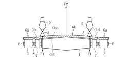
また、図2に示すように、このガラスフィルムの割断方法においては、離反工程の実行中に、有効部Gbにおける幅方向に沿って相互に離間した二箇所に、それぞれ厚み方向成分を有する第一の外力F1を負荷すると共に、上記二箇所の間に位置する箇所に、第一の外力F1とは逆向きの厚み方向成分を有する第二の外力F2を負荷することにより、有効部Gbを幅方向に沿って湾曲変形させる変形付与工程を実行する。この変形付与工程の実行により、有効部Gbと非有効部Gaとの間に形成される隙間の幅を拡張して、離反工程の実行中における有効部Gbと非有効部Gaとの接触を回避する。変形付与工程(離反工程)後の有効部Gbは、ロール状に巻き取ってガラスロールとする。
割断分離工程において割断の対象となる帯状ガラスフィルムGは、当該帯状ガラスフィルムGをロール状に巻き取ったガラスロールから連続的に巻き外したものである。そして、この巻き外した帯状ガラスフィルムGを、搬送手段(例えば、ベルトコンベア等)を用いて図1に矢印Tで示す方向に向けて水平に搬送している。なお、帯状ガラスフィルムGの厚みは200μm~300μmの範囲内となっている。
割断分離工程では、帯状ガラスフィルムGの有効部Gbと非有効部Gaとの境界となる割断予定線Xに沿って、レーザーの照射により局所的に加熱された加熱領域Hと、冷媒(例えば、霧状の水等)の噴射により局所的に冷却された冷却領域Cとを連続的に形成していく。これにより、両領域の温度差によって発生した熱応力を用いて帯状ガラスフィルムGを連続的に割断し、当該帯状ガラスフィルムGの有効部Gbと非有効部Gaとを分離する。なお、分離後の有効部Gbと非有効部Gaとの両者は、並列にした状態で水平に搬送している。
ここで、本実施形態においては、ガラスロールから連続的に巻き外した帯状ガラスフィルムGを割断の対象としているが、この限りではない。例えば、変形例として、ダウンドロー法によって連続的に成形された帯状ガラスフィルムGを割断の対象としてもよい。また、本実施形態では、水平に搬送される帯状ガラスフィルムGを割断する態様となっているが、変形例として、水平面に対して45°以下の範囲内で傾斜した傾斜方向に搬送される帯状ガラスフィルムGを割断する態様としてもよい。しかしながら、水平面に対する傾斜は小さいほどよく、好ましくは水平面に対して20°以下、より好ましくは10°以下、さらに好ましくは5°以下とする。
離反工程では、分離後に並列な状態で水平に搬送される有効部Gbと非有効部Gaとのうち、有効部Gbを継続して水平に搬送すると共に、非有効部Gaを有効部Gbの搬送経路から下方へと引き出して離脱させる。これにより、有効部Gbと非有効部Gaとを厚み方向に離反させる。
ここで、分離後の有効部Gbと非有効部Gaとを厚み方向に離反させる態様は、本実施形態のような態様に限られるものではない。例えば、変形例として、水平面に対して傾斜した傾斜方向に搬送しつつ、帯状ガラスフィルムGを割断して有効部Gbと非有効部Gaとを分離させたような場合には、以下のような態様によって離反工程を実行してもよい。すなわち、有効部Gbを継続して傾斜方向に搬送すると共に、非有効部Gaを有効部Gbの搬送経路から水平に引き出して離脱させ、有効部Gbと非有効部Gaとを厚み方向に離反させてもよい。
変形付与工程を実行する際の有効部Gbに対しては、当該有効部Gbの下面Gbbを支持する二つの支持ローラー1の各々によって第一の外力F1を負荷すると共に、有効部Gbの上面Gbaに向けて噴射した流体としてのエアーAによって第二の外力F2を負荷する。これにより、有効部Gbの搬送経路上における二つの支持ローラー1の近傍において、有効部Gbを自重によらず幅方向に沿って強制的に湾曲変形させる。そして、有効部Gbが湾曲変形している間に、上記の離反工程の実行に伴って非有効部Gaを有効部Gbの搬送経路から離脱させる。
二つの支持ローラー1の相互間には、有効部GbにおけるエアーAが噴射された箇所の下面Gbbを支持し、且つ二つの支持ローラー1よりも有効部Gbを支持する高さ位置が下方となる中間ローラー2を配置している。また、変形付与工程を実行する際、有効部Gbの搬送経路から離脱させる前の非有効部Gaは、ローラー3によって支持している。
二つの支持ローラー1及び中間ローラー2は、割断分離工程においてレーザー割断法を実行する位置(加熱領域H及び冷却領域Cが帯状ガラスフィルムGに形成される位置)から、有効部Gbの搬送経路に沿って下流側に離間した位置に配置されている。なお、レーザー割断法を実行する位置から、二つの支持ローラー1及び中間ローラー2までの距離は、有効部Gbの湾曲変形に伴って当該有効部Gbに作用する応力が、レーザー割断法を実行する位置まで伝播しない距離とすることが好ましい。
二つの支持ローラー1は、有効部Gbの幅方向中央Gbcを基準として対称に配置されており、有効部Gbの幅方向における一方側、及び他方側の端部Gbdをそれぞれ支持している。これにより、二つの支持ローラー1の各々から有効部Gbに第一の外力F1(有効部Gbを支持する力)が負荷される。中間ローラー2は、有効部Gbの幅方向に沿って長尺なローラーとされると共に、二つの支持ローラー1よりも径の小さいローラーとされている。二つの支持ローラー1と中間ローラー2との両者は、いずれもフリーローラーとされており、有効部Gbとの摩擦によって回転する。さらに、二つの支持ローラー1と中間ローラー2とは、共通した回転軸4を有している。
エアーAは、エアー噴射器5から有効部Gbの幅方向中央Gbcに向けて噴射している。これにより、エアーAによって有効部Gbに第二の外力F2(有効部Gbを下方へと押圧する力)が負荷される。エアー噴射器5は、有効部Gbの幅方向中央Gbcの上方において一基のみが配置されている。なお、本実施形態においては、第二の外力F2と、上記の第一の外力F1とにより、有効部Gbが幅方向中央Gbcを基準として対称に湾曲変形する。
ローラー3は、支持ローラー1に対して幅方向外側に配置されると共に、回転軸6の周りを回転するフリーローラーとされている。回転軸6は、二つの支持ローラー1及び中間ローラー2の回転軸4と同一な高さ位置に配置されている。また、ローラー3の径は、支持ローラー1の径よりも小さくなっており、中間ローラー2の径と同一な大きさとされている。これにより、支持ローラー1によって支持される有効部Gb(端部Gbd)と、ローラー3によって支持される非有効部Gaとの間に、両ローラー1,3間の径の大きさの差異に起因して高低差が生じるため、有効部Gb(端部Gbd)と非有効部Gaとの接触をより回避しやすくなる。
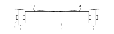
なお、図3に示すように、二つの支持ローラー1及び中間ローラー2を正面視した場合に、中間ローラー2の頂部(有効部Gbの下面Gbbと接触する部位)における中点と、支持ローラー1における有効部Gbの下面Gbbとの接触点との両点を結ぶ直線が、水平線に対して傾斜した角度θ1の大きさは、以下のような範囲内とすることが好ましい。すなわち、角度θ1が小さすぎると、有効部Gbが幅方向に沿って十分に湾曲変形せず、有効部Gbと非有効部Gaとの間に形成される隙間の幅を十分に拡張できないおそれがある。一方、角度θ1が大きすぎると、幅方向に沿って湾曲変形した有効部Gbの曲率が大きくなり、有効部Gbの湾曲変形に伴って当該有効部Gbに作用する応力が、レーザー割断法を実行する位置まで伝播するおそれが高まる。そのため、角度θ1は、好ましくは0.5°~5°とし、より好ましくは0.7°~3°とし、最も好ましくは1°~2°とする。
ここで、本実施形態においては、流体としてのエアーAを有効部Gbの上面Gbaに向けて噴射することにより、第二の外力F2を有効部Gbに負荷しているが、この限りではない。変形例として、他の気体や液体を噴射することにより、有効部Gbに第二の外力F2を負荷してもよい。また、エアーAを噴射する箇所は、必ずしも有効部Gbの幅方向中央Gbcでなくともよく、有効部Gbにおいて二つの支持ローラー1の相互間に位置する箇所であればよい。従って、変形例として、有効部Gbの幅方向中央Gbcからずれた箇所に向けてエアーAを噴射してもよい。さらに、変形例として、エアー噴射器5は複数配置してもよく、複数のエアー噴射器5によって有効部Gbの複数箇所(二つの支持ローラー1の相互間に位置する複数箇所)に向けてエアーAを噴射してもよい。この場合、有効部Gbには複数の第二の外力F2が負荷される。
また、本実施形態では、中間ローラー2が幅方向に沿って長尺なローラーとされているが、この限りではない。中間ローラー2は、有効部GbにおけるエアーAが噴射された箇所の下面Gbbを支持できさえすればよい。従って、変形例として、中間ローラー2を幅方向に沿って短尺なローラーとして、エアーAが噴射された箇所の下面Gbbのみを支持させてもよい。さらに、二つの支持ローラー1及び中間ローラー2は、必ずしもフリーローラーでなくともよく、変形例として、駆動ローラーを使用してもよい。この場合、有効部Gbの下面Gbbに擦り傷が発生することを防止するため、二つの支持ローラー1と中間ローラー2との間で、周速度を同一な速度とすることが好ましい。加えて、二つの支持ローラー1の各々が支持する箇所は、有効部Gbの幅方向の一方側、及び他方側の端部Gbdでなくともよく、変形例として、端部Gbdから幅方向内側へとずれた箇所であってもよい。
また、本実施形態では、有効部Gb(端部Gbd)と非有効部Gaとの接触を回避しやすくするため、有効部Gb(端部Gbd)と非有効部Gaとの間に高低差を生じさせている。そして、この目的のために、二つの支持ローラー1及び中間ローラー2の回転軸4と、ローラー3の回転軸6とを同一な高さ位置に配置した上で、ローラー3の径を支持ローラー1の径よりも小さくして、中間ローラー2の径と同一な大きさとしている。しかしながら、この限りではなく、有効部Gb(端部Gbd)と非有効部Gaとの間に高低差を生じさせるにあたっては、支持ローラー1が有効部Gb(端部Gbd)を支持する高さ位置に対してローラー3が非有効部Gaを支持する高さ位置を低くしさえすればよい。そのため、例えば、本実施形態とは異なり、ローラー3の径を中間ローラー2の径よりもさらに小さくしてもよい。また、例えば、支持ローラー1の径とローラー3の径とを同一な大きさとして、二つの支持ローラー1及び中間ローラー2の回転軸4よりもローラー3の回転軸6が下方に位置するように、両ローラー1,3を配置してもよい。
この第一実施形態に係るガラスフィルムの割断方法によれば、離反工程の実行中における有効部Gbは、変形付与工程の実行に伴って、相互に逆向きの厚み方向成分を有する第一の外力F1と第二の外力F2とにより、幅方向に沿って強制的に湾曲変形させられる。これにより、有効部Gbが幅方向に沿って湾曲変形した分だけ、有効部Gbと非有効部Gaとの間に形成される隙間の幅を拡張することができる。その結果、離反工程の実行中における有効部Gbと非有効部Gaとの接触を回避することが可能となる。
<第二実施形態>
以下、本発明の第二実施形態に係るガラスフィルムの割断方法について説明する。なお、この第二実施形態の説明において、上記の第一実施形態で既に説明した要素については、第二実施形態の説明で参照する図面に同一の符号を付すことで重複する説明を省略し、第一実施形態との相違点についてのみ説明する。
以下、本発明の第二実施形態に係るガラスフィルムの割断方法について説明する。なお、この第二実施形態の説明において、上記の第一実施形態で既に説明した要素については、第二実施形態の説明で参照する図面に同一の符号を付すことで重複する説明を省略し、第一実施形態との相違点についてのみ説明する。
図4に示すように、本発明の第二実施形態に係るガラスフィルムの割断方法が、上記の第一実施形態に係るガラスフィルムの割断方法と相違している点は、下記の三点である。(1)変形付与工程において、有効部Gbの上面Gba上の二箇所にそれぞれエアーAを噴射することにより、第一の外力F1を負荷すると共に、有効部Gbの下面Gbbを支持する支持ローラー1により、第二の外力F2を負荷している点。(2)支持ローラー1の形状、及び配置が異なっている点。(3)有効部Gbにおける幅方向の一方側、及び他方側の端部Gbdをそれぞれ下面Gbb側から支持するエッジローラー7を、支持ローラー1を幅方向に挟んで一方側と他方側とにそれぞれ配置している点。
エアーAがそれぞれ噴射される二箇所は、有効部Gbの幅方向中央Gbcを基準として対称な位置となっている。そして、この二箇所に噴射されたエアーAの各々によって有効部Gbに第一の外力F1(有効部Gbを下方へと押圧する力)が負荷される。
支持ローラー1は、有効部Gbの幅方向中央Gbcを基準として対称な形状を有し、且つ幅方向外側へと移行するに連れて漸次に径が縮小するローラーとなっている。この支持ローラー1は、その径が最大となる中央部一箇所で有効部Gbの幅方向中央Gbcを支持している。これにより、支持ローラー1(支持ローラー1の中央部)から有効部Gbに第二の外力F2(有効部Gbを支持する力)が負荷される。なお、支持ローラー1は、フリーローラーとされており、有効部Gbとの摩擦によって回転する。
エッジローラー7は、支持ローラー1よりも有効部Gbを支持する高さ位置が下方とされている。また、エッジローラー7の径は、支持ローラー1の中央部の径よりも小さくされると共に、ローラー3の径と同一な大きさとされている。さらに、エッジローラー7は、支持ローラー1と同様にフリーローラーとされており、有効部Gbとの摩擦によって回転する。なお、支持ローラー1とエッジローラー7とは、共通した回転軸8を有している。この回転軸8は、ローラー3の回転軸と同一な高さ位置に配置されている。
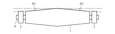
なお、図5に示すように、支持ローラー1及び二つのエッジローラー7を正面視した場合に、支持ローラー1の中央部における有効部Gbの下面Gbbとの接触点と、エッジローラー7における有効部Gbの下面Gbbとの接触点との両点を結ぶ直線が、水平線に対して傾斜した角度θ2の大きさは、以下のような範囲内とすることが好ましい。すなわち、上記の第一実施形態の説明で角度θ1について好ましい大きさを示した理由と同様の理由により、好ましくは0.5°~5°とし、より好ましくは0.7°~3°とし、最も好ましくは1°~2°とする。
ここで、本実施形態においては、支持ローラー1が、その中央部で有効部Gbの幅方向中央Gbcを支持する態様となっているが、この限りではない。変形例として、支持ローラー1において中央部からずれた位置に径が最大となる箇所を設け、支持ローラー1が有効部Gbの幅方向中央Gbcからずれた箇所を支持する態様としてもよい。また、変形例として、支持ローラー1が有効部Gbの下面Gbbを支持する箇所を複数箇所としてもよい。この場合、有効部Gbには複数の第二の外力F2が負荷される。
この第二実施形態に係るガラスフィルムの割断方法によっても、上記の第一実施形態に係るガラスフィルムの割断方法と同一の作用・効果を得ることが可能である。
<第三実施形態>
以下、本発明の第三実施形態に係るガラスフィルムの割断方法について説明する。なお、この第三実施形態の説明においても、上記の第一実施形態で既に説明した要素については、第三実施形態の説明で参照する図面に同一の符号を付すことで重複する説明を省略し、第一実施形態との相違点についてのみ説明する。
以下、本発明の第三実施形態に係るガラスフィルムの割断方法について説明する。なお、この第三実施形態の説明においても、上記の第一実施形態で既に説明した要素については、第三実施形態の説明で参照する図面に同一の符号を付すことで重複する説明を省略し、第一実施形態との相違点についてのみ説明する。
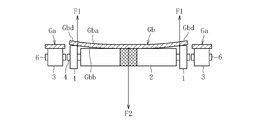
図6に示すように、本発明の第三実施形態に係るガラスフィルムの割断方法が、上記の第一実施形態に係るガラスフィルムの割断方法と相違している点は、下記の二点である。(1)変形付与工程において、有効部Gbの下面Gbbを吸引することによって第二の外力F2を負荷している点。(2)中間ローラー2が外周部(図6においてクロスハッチングを施した箇所)に有効部Gbの下面Gbbを吸引するための吸引孔を有している点。
中間ローラー2は、その外周部に多数の吸引孔が形成されており、各吸引孔は負圧を発生させるための負圧発生手段(例えば、真空ポンプ等)と繋がっている。そして、負圧発生手段の稼働に伴って、多数の吸引孔が有効部Gbの下面Gbbを吸引する。この吸引によって有効部Gbに第二の外力F2(有効部Gbを下方に吸引する力)が負荷される。なお、多数の吸引孔は中間ローラー2の中央部一箇所に配置されており、多数の吸引孔は有効部Gbの幅方向中央Gbcを吸引する。
ここで、本実施形態においては、中間ローラー2の外周部に形成された多数の吸引孔が有効部Gbの幅方向中央Gbcを吸引する態様となっているが、この限りではない。変形例として、多数の吸引孔を中間ローラー2の中央部からずれた箇所に配置して、多数の吸引孔が有効部Gbの幅方向中央Gbcからずれた箇所を吸引する態様としてもよい。また、変形例として、多数の吸引孔を有効部Gbの幅方向に沿って中間ローラー2の複数箇所に配置して、有効部Gbの複数箇所を吸引する態様としてもよい。この場合、有効部Gbには複数の第二の外力F2が負荷される。
この第三実施形態に係るガラスフィルムの割断方法によっても、上記の第一実施形態に係るガラスフィルムの割断方法と同一の作用・効果を得ることが可能である。
<第四実施形態>
以下、本発明の第四実施形態に係るガラスフィルムの割断方法について説明する。この第四実施形態は、上記の第二実施形態と類似した態様であるため、第四実施形態の説明において、上記の第二実施形態で既に説明した要素については、第四実施形態の説明で参照する図面に同一の符号を付すことで重複する説明を省略し、第二実施形態との相違点についてのみ説明する。
以下、本発明の第四実施形態に係るガラスフィルムの割断方法について説明する。この第四実施形態は、上記の第二実施形態と類似した態様であるため、第四実施形態の説明において、上記の第二実施形態で既に説明した要素については、第四実施形態の説明で参照する図面に同一の符号を付すことで重複する説明を省略し、第二実施形態との相違点についてのみ説明する。
図7に示すように、本発明の第四実施形態に係るガラスフィルムの割断方法が、上記の第二実施形態に係るガラスフィルムの割断方法と相違している点は、下記の二点である。(1)有効部Gbの下面Gbb上の二箇所をそれぞれ吸引することにより、第一の外力F1を負荷している点。(2)支持ローラー1が外周部(図7においてクロスハッチングを施した箇所)に有効部Gbの下面Gbbを吸引するための吸引孔を有している点。
支持ローラー1は、その外周部の二箇所にそれぞれ多数の吸引孔が形成されており、各吸引孔は負圧を発生させるための負圧発生手段(例えば、真空ポンプ等)と繋がっている。そして、負圧発生手段の稼働に伴って、多数の吸引孔が有効部Gbの下面Gbbを吸引する。この吸引によって有効部Gbの二箇所にそれぞれ第一の外力F1(有効部Gbを下方に吸引する力)が負荷される。なお、支持ローラー1において、多数の吸引孔が形成された二箇所は、有効部Gbの幅方向中央Gbcを基準として対称に配置されている。
この第四実施形態に係るガラスフィルムの割断方法によっても、上記の第一実施形態に係るガラスフィルムの割断方法と同一の作用・効果を得ることが可能である。
ここで、本発明に係るガラスフィルムの割断方法は、上記の各実施形態で説明した態様に限定されるものではない。例えば、上記の第一及び第三実施形態の変形例として、中間ローラーは、二つの支持ローラーと同一な径を有し、且つ二つの支持ローラーよりも下方に配置されたローラーとしてもよい。
1 支持ローラー
2 中間ローラー
4 回転軸
7 エッジローラー
8 回転軸
G 帯状ガラスフィルム
Ga 非有効部
Gb 有効部
Gba 上面
Gbb 下面
Gbc 幅方向中央
Gbd 端部
A エアー
F1 第一の外力
F2 第二の外力
2 中間ローラー
4 回転軸
7 エッジローラー
8 回転軸
G 帯状ガラスフィルム
Ga 非有効部
Gb 有効部
Gba 上面
Gbb 下面
Gbc 幅方向中央
Gbd 端部
A エアー
F1 第一の外力
F2 第二の外力
Claims (20)
- 平置き姿勢で搬送中の帯状ガラスフィルムをレーザー割断法によって長手方向に沿って連続的に割断することで、前記帯状ガラスフィルムの幅方向両端にそれぞれ存する非有効部と、両非有効部の間に存する有効部とを分離させる割断分離工程と、
分離後の前記非有効部を分離後の前記有効部の搬送経路から離脱させることで、前記非有効部と前記有効部とを厚み方向に離反させる離反工程とを含んだガラスフィルムの割断方法において、
前記離反工程の実行中に、前記有効部における幅方向に沿って相互に離間した二箇所に、それぞれ厚み方向成分を有する第一の外力を負荷すると共に、前記二箇所の間に位置する箇所に、前記第一の外力とは逆向きの厚み方向成分を有する第二の外力を負荷することにより、前記有効部を幅方向に沿って湾曲変形させる変形付与工程を実行することを特徴とするガラスフィルムの割断方法。 - 前記有効部の下面を支持する二つの支持ローラーの各々により、前記第一の外力を負荷すると共に、前記有効部の上面に向けて噴射した流体により、前記第二の外力を負荷することを特徴とする請求項1に記載のガラスフィルムの割断方法。
- 前記有効部における前記流体が噴射された箇所の下面を支持し、且つ前記二つの支持ローラーよりも前記有効部を支持する高さ位置が下方となる中間ローラーを、前記二つの支持ローラーの相互間に配置することを特徴とする請求項2に記載のガラスフィルムの割断方法。
- 前記中間ローラーを、前記二つの支持ローラーと共通した回転軸を有し、且つ該二つの支持ローラーよりも径の小さいローラーとすることを特徴とする請求項3に記載のガラスフィルムの割断方法。
- 前記二つの支持ローラー及び前記中間ローラーを、フリーローラーとすることを特徴とする請求項3又は4に記載のガラスフィルムの割断方法。
- 前記有効部の幅方向中央を基準として前記二つの支持ローラーを対称に配置すると共に、前記有効部の幅方向中央に向けて前記流体を噴射することを特徴とする請求項2~5のいずれかに記載のガラスフィルムの割断方法。
- 前記二つの支持ローラーに前記有効部の幅方向両端部をそれぞれ支持させることを特徴とする請求項2~6のいずれかに記載のガラスフィルムの割断方法。
- 前記有効部の上面上の二箇所にそれぞれ噴射した流体により、前記第一の外力を負荷すると共に、前記有効部の下面を支持する支持ローラーにより、前記第二の外力を負荷することを特徴とする請求項1に記載のガラスフィルムの割断方法。
- 前記有効部における幅方向両端部をそれぞれ下面側から支持し、且つ前記支持ローラーよりも前記有効部を支持する高さ位置が下方となるエッジローラーを、前記支持ローラーを幅方向に挟んで一方側と他方側とにそれぞれ配置することを特徴とする請求項8に記載のガラスフィルムの割断方法。
- 前記支持ローラー及び前記エッジローラーを、フリーローラーとしたことを特徴とする請求項9に記載のガラスフィルムの割断方法。
- 前記有効部の幅方向中央を基準として前記流体が噴射される前記二箇所を対称な位置とすると共に、前記有効部の幅方向中央を前記支持ローラーに支持させることを特徴とする請求項8~10のいずれかに記載のガラスフィルムの割断方法。
- 前記支持ローラーを、前記有効部の幅方向中央を基準として対称な形状を有し、且つ幅方向外側へと移行するに連れて漸次に径が縮小するローラーとすることを特徴とする請求項11に記載のガラスフィルムの割断方法。
- 前記有効部の下面を支持する二つの支持ローラーの各々により、前記第一の外力を負荷すると共に、前記有効部の下面を吸引することにより、前記第二の外力を負荷することを特徴とする請求項1に記載のガラスフィルムの割断方法。
- 前記有効部の下面を吸引するための吸引孔を外周部に有し、且つ前記二つの支持ローラーよりも前記有効部を支持する高さ位置が下方となる中間ローラーを、前記二つの支持ローラーの相互間に配置することを特徴とする請求項13に記載のガラスフィルムの割断方法。
- 前記中間ローラーを、前記二つの支持ローラーと共通した回転軸を有し、且つ該二つの支持ローラーよりも径の小さいローラーとすることを特徴とする請求項14に記載のガラスフィルムの割断方法。
- 前記二つの支持ローラー及び前記中間ローラーを、フリーローラーとすることを特徴とする請求項14又は15に記載のガラスフィルムの割断方法。
- 前記有効部の幅方向中央を基準として前記二つの支持ローラーを対称に配置すると共に、前記有効部の幅方向中央を吸引することを特徴とする請求項13~16のいずれかに記載のガラスフィルムの割断方法。
- 前記二つの支持ローラーに前記有効部の幅方向両端部をそれぞれ支持させることを特徴とする請求項13~17のいずれかに記載のガラスフィルムの割断方法。
- 前記有効部の下面上の二箇所をそれぞれ吸引することにより、前記第一の外力を負荷すると共に、前記有効部の下面を支持する支持ローラーにより、前記第二の外力を負荷することを特徴とする請求項1に記載のガラスフィルムの割断方法。
- 前記帯状ガラスフィルムの厚みが200μm~300μmの範囲内であることを特徴とする請求項1~19のいずれかに記載のガラスフィルムの割断方法。
Priority Applications (2)
| Application Number | Priority Date | Filing Date | Title |
|---|---|---|---|
| KR1020177012582A KR102357543B1 (ko) | 2015-02-25 | 2016-01-28 | 유리 필름의 할단 방법 |
| CN201680003661.7A CN107001104B (zh) | 2015-02-25 | 2016-01-28 | 玻璃膜的切割方法 |
Applications Claiming Priority (2)
| Application Number | Priority Date | Filing Date | Title |
|---|---|---|---|
| JP2015035310A JP6424674B2 (ja) | 2015-02-25 | 2015-02-25 | ガラスフィルムの割断方法 |
| JP2015-035310 | 2015-02-25 |
Publications (1)
| Publication Number | Publication Date |
|---|---|
| WO2016136368A1 true WO2016136368A1 (ja) | 2016-09-01 |
Family
ID=56788374
Family Applications (1)
| Application Number | Title | Priority Date | Filing Date |
|---|---|---|---|
| PCT/JP2016/052436 Ceased WO2016136368A1 (ja) | 2015-02-25 | 2016-01-28 | ガラスフィルムの割断方法 |
Country Status (5)
| Country | Link |
|---|---|
| JP (1) | JP6424674B2 (ja) |
| KR (1) | KR102357543B1 (ja) |
| CN (1) | CN107001104B (ja) |
| TW (1) | TWI671268B (ja) |
| WO (1) | WO2016136368A1 (ja) |
Families Citing this family (5)
| Publication number | Priority date | Publication date | Assignee | Title |
|---|---|---|---|---|
| JP6738043B2 (ja) * | 2016-05-31 | 2020-08-12 | 日本電気硝子株式会社 | ガラスフィルムの製造方法 |
| JP6796282B2 (ja) * | 2016-10-11 | 2020-12-09 | 日本電気硝子株式会社 | ガラスフィルムの製造方法 |
| JP6829814B2 (ja) * | 2017-03-13 | 2021-02-17 | 日本電気硝子株式会社 | ガラスフィルムの製造方法 |
| CN112429948B (zh) * | 2020-12-02 | 2022-04-12 | 万津实业(赤壁)有限公司 | 曲面玻璃加工方法 |
| CN117446500B (zh) * | 2023-12-25 | 2024-03-29 | 成都中嘉微视科技有限公司 | 一种可调式调节系统 |
Citations (5)
| Publication number | Priority date | Publication date | Assignee | Title |
|---|---|---|---|---|
| JP2012031031A (ja) * | 2010-08-02 | 2012-02-16 | Nippon Electric Glass Co Ltd | ガラスフィルムの割断方法 |
| JP2012111649A (ja) * | 2010-11-22 | 2012-06-14 | Nippon Electric Glass Co Ltd | 帯状ガラスフィルム割断装置及び帯状ガラスフィルム割断方法 |
| WO2012169025A1 (ja) * | 2011-06-08 | 2012-12-13 | 日本電気硝子株式会社 | 板状ガラスの切断方法及びその切断装置 |
| WO2014085357A1 (en) * | 2012-11-29 | 2014-06-05 | Corning Incorporated | Methods and apparatus for fabricating glass ribbon of varying widths |
| JP2015502898A (ja) * | 2011-10-07 | 2015-01-29 | ショット アクチエンゲゼルシャフトSchott AG | 縁部が特殊に形成された薄手ガラスを切断する方法 |
Family Cites Families (7)
| Publication number | Priority date | Publication date | Assignee | Title |
|---|---|---|---|---|
| JPH0229115A (ja) * | 1988-07-19 | 1990-01-31 | Toshiba Corp | 出力回路 |
| US20060261118A1 (en) * | 2005-05-17 | 2006-11-23 | Cox Judy K | Method and apparatus for separating a pane of brittle material from a moving ribbon of the material |
| JP2012096936A (ja) * | 2010-10-29 | 2012-05-24 | Asahi Glass Co Ltd | ガラスリボンの耳切断装置および耳切断方法とガラス製品の製造装置および製造方法 |
| US9862634B2 (en) * | 2011-08-12 | 2018-01-09 | Corning Incorporated | Method and apparatus for removing peripheral portion of a glass sheet |
| US8756817B2 (en) * | 2011-11-30 | 2014-06-24 | Corning Incorporated | Method and apparatus for removing peripheral portion of a glass sheet |
| US9643878B2 (en) * | 2012-11-13 | 2017-05-09 | Nippon Electric Glass Co., Ltd. | Sheet glass manufacturing method and manufacturing device |
| KR101948382B1 (ko) * | 2013-01-30 | 2019-02-14 | 코닝 인코포레이티드 | 가요성 유리의 연속 레이저 절단을 위한 장치 및 방법 |
-
2015
- 2015-02-25 JP JP2015035310A patent/JP6424674B2/ja active Active
-
2016
- 2016-01-28 KR KR1020177012582A patent/KR102357543B1/ko active Active
- 2016-01-28 CN CN201680003661.7A patent/CN107001104B/zh active Active
- 2016-01-28 WO PCT/JP2016/052436 patent/WO2016136368A1/ja not_active Ceased
- 2016-02-04 TW TW105103822A patent/TWI671268B/zh active
Patent Citations (5)
| Publication number | Priority date | Publication date | Assignee | Title |
|---|---|---|---|---|
| JP2012031031A (ja) * | 2010-08-02 | 2012-02-16 | Nippon Electric Glass Co Ltd | ガラスフィルムの割断方法 |
| JP2012111649A (ja) * | 2010-11-22 | 2012-06-14 | Nippon Electric Glass Co Ltd | 帯状ガラスフィルム割断装置及び帯状ガラスフィルム割断方法 |
| WO2012169025A1 (ja) * | 2011-06-08 | 2012-12-13 | 日本電気硝子株式会社 | 板状ガラスの切断方法及びその切断装置 |
| JP2015502898A (ja) * | 2011-10-07 | 2015-01-29 | ショット アクチエンゲゼルシャフトSchott AG | 縁部が特殊に形成された薄手ガラスを切断する方法 |
| WO2014085357A1 (en) * | 2012-11-29 | 2014-06-05 | Corning Incorporated | Methods and apparatus for fabricating glass ribbon of varying widths |
Also Published As
| Publication number | Publication date |
|---|---|
| JP2016155716A (ja) | 2016-09-01 |
| JP6424674B2 (ja) | 2018-11-21 |
| TWI671268B (zh) | 2019-09-11 |
| CN107001104B (zh) | 2020-03-13 |
| TW201634414A (zh) | 2016-10-01 |
| CN107001104A (zh) | 2017-08-01 |
| KR102357543B1 (ko) | 2022-02-03 |
| KR20170118683A (ko) | 2017-10-25 |
Similar Documents
| Publication | Publication Date | Title |
|---|---|---|
| JP5617556B2 (ja) | 帯状ガラスフィルム割断装置及び帯状ガラスフィルム割断方法 | |
| JP2016155716A (ja) | ガラスフィルムの割断方法 | |
| US9676579B2 (en) | Manufacturing method for a glass roll and manufacturing apparatus for a glass roll | |
| US9840028B2 (en) | Cleaving method for a glass film | |
| JP6108175B2 (ja) | 初期クラック形成装置、及び形成方法 | |
| JP2015174694A (ja) | ガラスフィルム及びガラスロール | |
| JP2014101269A (ja) | ガラスフィルムの切断方法 | |
| JP2018062430A (ja) | ガラスフィルムの製造方法 | |
| WO2017208677A1 (ja) | ガラスフィルムの製造方法 | |
| WO2018168381A1 (ja) | ガラスフィルムの製造方法 | |
| WO2016167074A1 (ja) | ガラスフィルムの製造方法 | |
| WO2014024931A1 (ja) | 強化ガラスの割断方法 | |
| JP6136070B2 (ja) | ガラスフィルムリボン製造方法及びガラスフィルムリボン製造装置 | |
| WO2013099893A1 (ja) | ガラス基板のエッチング方法 | |
| JP6331454B2 (ja) | スクライブ装置 | |
| WO2016011114A1 (en) | Methods and apparatus for controlled laser cutting of flexible glass | |
| JP2012089650A (ja) | ガラス板搬送方法及びガラス板搬送装置 | |
| WO2017043306A1 (ja) | ガラス板の製造方法及びその製造装置 | |
| WO2015072819A1 (ko) | 플렉시블 기판 접합방법 | |
| JP4081533B2 (ja) | ガラス基板分割方法 | |
| JP5930156B2 (ja) | 薄板状ワーク搬送装置及び薄板状ワーク搬送方法 | |
| JP6402940B2 (ja) | スクライブ装置 | |
| JP2015178407A (ja) | 板状物搬送方法および板状物搬送装置並びに当該板状物搬送装置を備える板状物の生産装置 |
Legal Events
| Date | Code | Title | Description |
|---|---|---|---|
| 121 | Ep: the epo has been informed by wipo that ep was designated in this application |
Ref document number: 16755118 Country of ref document: EP Kind code of ref document: A1 |
|
| ENP | Entry into the national phase |
Ref document number: 20177012582 Country of ref document: KR Kind code of ref document: A |
|
| NENP | Non-entry into the national phase |
Ref country code: DE |
|
| 122 | Ep: pct application non-entry in european phase |
Ref document number: 16755118 Country of ref document: EP Kind code of ref document: A1 |