WO2016136347A1 - スプレイノズル及び脱気器 - Google Patents
スプレイノズル及び脱気器 Download PDFInfo
- Publication number
- WO2016136347A1 WO2016136347A1 PCT/JP2016/051928 JP2016051928W WO2016136347A1 WO 2016136347 A1 WO2016136347 A1 WO 2016136347A1 JP 2016051928 W JP2016051928 W JP 2016051928W WO 2016136347 A1 WO2016136347 A1 WO 2016136347A1
- Authority
- WO
- WIPO (PCT)
- Prior art keywords
- spray nozzle
- outer cylinder
- condensate
- inner cylinder
- container
- Prior art date
- Legal status (The legal status is an assumption and is not a legal conclusion. Google has not performed a legal analysis and makes no representation as to the accuracy of the status listed.)
- Ceased
Links
Images




Classifications
-
- F—MECHANICAL ENGINEERING; LIGHTING; HEATING; WEAPONS; BLASTING
- F22—STEAM GENERATION
- F22D—PREHEATING, OR ACCUMULATING PREHEATED, FEED-WATER FOR STEAM GENERATION; FEED-WATER SUPPLY FOR STEAM GENERATION; CONTROLLING WATER LEVEL FOR STEAM GENERATION; AUXILIARY DEVICES FOR PROMOTING WATER CIRCULATION WITHIN STEAM BOILERS
- F22D1/00—Feed-water heaters, i.e. economisers or like preheaters
- F22D1/28—Feed-water heaters, i.e. economisers or like preheaters for direct heat transfer, e.g. by mixing water and steam
-
- B—PERFORMING OPERATIONS; TRANSPORTING
- B01—PHYSICAL OR CHEMICAL PROCESSES OR APPARATUS IN GENERAL
- B01D—SEPARATION
- B01D19/00—Degasification of liquids
- B01D19/0005—Degasification of liquids with one or more auxiliary substances
- B01D19/001—Degasification of liquids with one or more auxiliary substances by bubbling steam through the liquid
-
- B—PERFORMING OPERATIONS; TRANSPORTING
- B05—SPRAYING OR ATOMISING IN GENERAL; APPLYING FLUENT MATERIALS TO SURFACES, IN GENERAL
- B05B—SPRAYING APPARATUS; ATOMISING APPARATUS; NOZZLES
- B05B1/00—Nozzles, spray heads or other outlets, with or without auxiliary devices such as valves, heating means
- B05B1/14—Nozzles, spray heads or other outlets, with or without auxiliary devices such as valves, heating means with multiple outlet openings; with strainers in or outside the outlet opening
- B05B1/16—Nozzles, spray heads or other outlets, with or without auxiliary devices such as valves, heating means with multiple outlet openings; with strainers in or outside the outlet opening having selectively- effective outlets
-
- B—PERFORMING OPERATIONS; TRANSPORTING
- B05—SPRAYING OR ATOMISING IN GENERAL; APPLYING FLUENT MATERIALS TO SURFACES, IN GENERAL
- B05B—SPRAYING APPARATUS; ATOMISING APPARATUS; NOZZLES
- B05B1/00—Nozzles, spray heads or other outlets, with or without auxiliary devices such as valves, heating means
- B05B1/30—Nozzles, spray heads or other outlets, with or without auxiliary devices such as valves, heating means designed to control volume of flow, e.g. with adjustable passages
- B05B1/32—Nozzles, spray heads or other outlets, with or without auxiliary devices such as valves, heating means designed to control volume of flow, e.g. with adjustable passages in which a valve member forms part of the outlet opening
-
- F—MECHANICAL ENGINEERING; LIGHTING; HEATING; WEAPONS; BLASTING
- F22—STEAM GENERATION
- F22D—PREHEATING, OR ACCUMULATING PREHEATED, FEED-WATER FOR STEAM GENERATION; FEED-WATER SUPPLY FOR STEAM GENERATION; CONTROLLING WATER LEVEL FOR STEAM GENERATION; AUXILIARY DEVICES FOR PROMOTING WATER CIRCULATION WITHIN STEAM BOILERS
- F22D1/00—Feed-water heaters, i.e. economisers or like preheaters
- F22D1/50—Feed-water heaters, i.e. economisers or like preheaters incorporating thermal de-aeration of feed-water
-
- F—MECHANICAL ENGINEERING; LIGHTING; HEATING; WEAPONS; BLASTING
- F22—STEAM GENERATION
- F22B—METHODS OF STEAM GENERATION; STEAM BOILERS
- F22B37/00—Component parts or details of steam boilers
- F22B37/02—Component parts or details of steam boilers applicable to more than one kind or type of steam boiler
Definitions
- the present invention relates to a spray nozzle used in a deaerator for removing impurities such as dissolved oxygen from feed water, and a deaerator using the spray nozzle.
- steam generated in a nuclear reactor is sent to a turbine generator to generate power, and the used steam is cooled by a condenser and returned to the reactor as condensate.
- the steam used to drive the turbine is cooled by cooling water in a condenser and returned to condensate (low-pressure saturated liquid), and then deaerator through a low-pressure feed water heater by a condensate pump.
- the deaerator removes impurities such as dissolved oxygen and uncondensed gas in the condensate, and then heats the condensate with a high-pressure feed water heater or the like with a main feed pump and then returns it to the steam generator.
- a bubbling type deaerator as a conventional deaerator.
- the bubbling type deaerator is provided with a spray nozzle at the top, and condensate is jetted downward by the spray nozzle, while a large number of bubbles are formed by jetting heated steam into the water storage section. Then, when the condensate and the heating steam come into contact with each other, oxygen in the condensate is transferred to the heating steam and can be deaerated.
- a deaerator there exist some which were described in the following patent document, for example.
- the deaerator ejects condensate from the upper spray nozzle, and brings this condensed water into contact with the heating steam, whereby oxygen dissolved in the condensate is transferred to the heating steam and removed. Therefore, when the deaerator becomes large, there is a problem that the pressure loss in the large flow rate region increases in the conventional spray nozzle.
- This invention solves the subject mentioned above, and aims at providing the spray nozzle and deaerator which aim at the performance improvement by suppressing the increase in the pressure loss which generate
- the spray nozzle of the present invention for achieving the above object is a spray nozzle for jetting condensate into a deaerator container, and an outer cylinder provided with a plurality of jet outlets on the outer periphery, and the outer cylinder
- An inner cylinder that is supported in the axial direction so as to be movable in the axial direction and is provided with a plurality of first communication holes that can communicate with the plurality of jet nozzles, and a shaft portion that is connected to the inner cylinder and that is a tip portion of the shaft portion
- the valve body provided on the opening / closing valve has an opening / closing valve capable of opening / closing the tip opening of the outer cylinder.
- a partition plate provided with a plurality of second communication holes is connected to a tip portion of the inner cylinder, and the shaft portion is arranged along an axial direction of the inner cylinder. It is characterized by being connected through.
- the movement of the opening / closing valve and the inner cylinder can be easily synchronized, and a predetermined amount of condensate is introduced into the opening of the outer cylinder by the second communication hole. Can be supplied.
- the valve body when the valve body is in a first opening position that opens the distal end opening of the outer cylinder, the plurality of ejection ports and the plurality of first communication holes do not communicate with each other, and the valve body Is in the second open position where the front end opening of the outer cylinder is opened, the plurality of jet outlets and the plurality of first communication holes communicate with each other.
- the first communication hole is a long hole along the axial direction of the inner cylinder.
- the first communication hole and the ejection port can be easily communicated with each other.
- the spray nozzle of the present invention is characterized in that the plurality of jet nozzles are provided at predetermined intervals in the axial direction of the outer cylinder.
- the spray nozzle of the present invention is characterized in that the jet port has a tapered shape with an opening area increasing toward the outside.
- the condensate can be ejected over a wide range from the ejection port, and the ejection resistance at this time can be reduced.
- the outer cylinder is characterized in that a mounting flange is provided on the outer peripheral portion.
- the mounting workability can be improved, and it can be easily removed and the maintainability can be improved.
- the deaerator of the present invention includes a container having a hollow shape and having an outlet at the lower part, the spray nozzle provided at the upper part of the container, and a heated steam jet for ejecting heated steam at the lower part of the container. And a distribution device.
- the spray nozzle spouts condensate into the container and the heating steam is ejected from the heating steam jetting device to this condensate, the condensate and the heating steam come into contact with each other, so that oxygen in the condensate is It moves to heated steam and is deaerated.
- the spray nozzle ejects condensate from the tip and side portions, the spray flow rate can be increased, and performance can be improved by suppressing an increase in pressure loss that occurs regardless of the jet flow rate at that time. Can be improved.
- the spray nozzle and the deaerator of the present invention since the spray nozzle ejects condensate from the tip and side portions, the ejection flow rate can be increased, and the pressure loss that occurs regardless of the ejection flow rate at that time The performance can be improved by suppressing the increase.
- FIG. 1 is a schematic view showing a deaerator using the spray nozzle of the first embodiment.
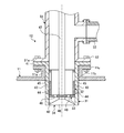
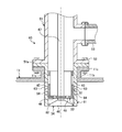
- FIG. 2 is a cross-sectional view of the spray nozzle of the first embodiment.
- FIG. 3 is a perspective view showing an outer cylinder.
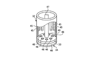
- FIG. 4 is a perspective view showing the inner cylinder.
- FIG. 5 is a cross-sectional view of the spray nozzle when a small flow rate condensate is ejected.
- FIG. 6 is a cross-sectional view of the spray nozzle at the time of ejection of the medium flow rate condensate.
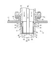
- FIG. 7 is a cross-sectional view of the spray nozzle when a large flow rate condensate is ejected.
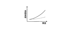
- FIG. 8 is a graph showing the channel area with respect to the opening of the spray nozzle.
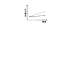
- FIG. 9 is a graph showing the flow velocity with respect to the opening of the spray nozzle.
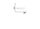
- FIG. 10 is a graph showing the pressure loss with respect to the opening of the spray nozzle.
- FIG. 11 is a cross-sectional view of the spray nozzle of the second embodiment.
- the nuclear reactor heats the primary cooling water into high-temperature and high-pressure steam and supplies it to a steam generator.
- the steam generator generates steam by heating the secondary cooling water with the steam (primary cooling water), and the generator generates power by driving the steam turbine with the steam.
- the condenser cools the steam that has driven the steam turbine with cooling water (seawater) and returns it to condensate (low-pressure saturated liquid), and then supplies it to the deaerator through the low-pressure feed water heater by the condensate pump.
- the deaerator removes impurities such as dissolved oxygen and uncondensed gas in the condensate, and then heats the condensate with a high-pressure feed water heater or the like by the main feed water pump and returns it to the steam generator.
- FIG. 1 is a schematic view showing a deaerator using the spray nozzle of the first embodiment.
- the deaerator 10 includes a container (deaerator container) 11, a spray nozzle 12, and a heating steam supply device 13.
- the container 11 has a hollow shape, and both end portions in the longitudinal direction of the horizontally long cylindrical portion are closed by curved lid portions.
- the container 11 is provided with a plurality of (two in this embodiment) spray nozzles 12 at the top.
- the spray nozzle 12 is configured to jet the steam condensate generated by being cooled by a condenser into the container 11 after being heated by a low-pressure feed water heater.
- the spray nozzle 12 is disposed at the upper end of the container 11 and at both ends in the longitudinal direction of the container 11, and jets condensate upward in the container 11. Further, the container 11 is provided with an outlet 21 for discharging this condensate.
- the container 11 is provided with a heating steam jetting device 13 for jetting heating steam below the inside.
- the heating steam ejection and distribution device 13 includes a heating steam pipe 22, a heating steam supply pipe 23, and a heating steam ejection pipe 24.
- the heating steam pipe 22 is arranged in the upper part of the container 11 along the longitudinal direction of the container 11.
- the heating steam supply pipe 23 penetrates the upper part of the container 11 from the outside of the container 11 and is connected to the intermediate portion in the longitudinal direction of the heating steam pipe 22.
- the heating steam jet pipe 24 extends downward from both ends in the longitudinal direction of the heating steam pipe 22.
- a plurality of the heating steam jet pipes 24 are provided at predetermined intervals in the longitudinal direction of the heating steam pipe 22, a base end portion (upper end portion) is connected to the heating steam pipe 22, and a distal end portion (lower end portion) is provided.
- a plurality of jetting ports (not shown) are formed extending to the bottom side of the container 11.
- each spray nozzle 12 ejects condensate into the container 11 a predetermined amount of condensate is stored in the container 11.
- the heating steam jet distribution device 13 supplies the heating steam from the heating steam pipe 22 to the plurality of heating steam ejection pipes 24 through the heating steam supply pipe 23
- each heating steam ejection pipe 24 returns from the plurality of jet outlets at the lower part. Heat steam is spouted into the water. Then, when the condensate stored in the container 11 and the heated steam ejected from the ejection port come into contact with each other, oxygen dissolved in the condensate is transferred to the heated steam and removed.
- FIG. 2 is a cross-sectional view of the spray nozzle of the first embodiment
- FIG. 3 is a perspective view showing an outer cylinder
- FIG. 4 is a perspective view showing an inner cylinder
- FIG. 5 is a spray at the time of ejection of a small flow rate condensate.
- FIG. 6 is a sectional view of the spray nozzle when the medium flow rate condensate is ejected
- FIG. 7 is a sectional view of the spray nozzle when the large flow rate condensate is ejected.
- the container 11 has a mounting opening 11b formed by a nozzle 11a and a mounting flange 11c.
- the spray nozzle 12 includes an outer cylinder 31, an inner cylinder 32, a partition plate 33, and an on-off valve 34.
- the spray nozzle 12 is fitted into the mounting opening 11b of the nozzle 11a in the container 11 and is mounted by a mounting flange 11c.
- the outer cylinder 31 has a cylindrical shape, and a mounting flange 41 having a ring shape extending to the outer diameter side is integrally provided at the base end portion (upper end portion), and the distal end portion A tip opening 42 is formed at the (lower end). Further, the outer cylinder 31 is provided with a plurality of jet outlets 43 and 44 on the outer peripheral portion.
- the plurality of jet nozzles 43 are formed at predetermined intervals (equal intervals) in the circumferential direction on the base end side of the outer cylinder 31.
- the plurality of jet nozzles 44 are formed at predetermined intervals (equal intervals) in the circumferential direction on the distal end side of the outer cylinder 31.
- the ejection ports 43 and 44 are formed at predetermined intervals in the axial direction of the outer cylinder 31.
- the jet nozzles 43 and 44 are arranged in a lattice shape opposed in the axial direction, they may be arranged in a staggered pattern shifted in the circumferential direction.
- the inner cylinder 32 has a cylindrical shape like the outer cylinder 31, and has a base end (upper end) and a distal end (lower end) open.
- the inner cylinder 32 is set to have an outer diameter slightly smaller than the inner diameter of the outer cylinder 31 and is supported inside the outer cylinder 31 so as to be movable in the axial direction.
- the inner cylinder 32 is provided with a plurality of first communication holes 45 that can communicate with the plurality of jet nozzles 43 and 44.
- the plurality of first communication holes 45 are long holes along the axial direction of the inner cylinder 32 and are formed at predetermined intervals (equal intervals) in the circumferential direction.
- the plurality of first communication holes 45 have the same position and number in the circumferential direction as the number and position of the ejection ports 43 and 44 in the circumferential direction.
- the first communication hole 45 has a width that substantially matches the inner diameter of the jet nozzles 43 and 44, and a length that substantially matches the axial distance between the jet nozzle 43 and the jet nozzle 44.
- the partition plate 33 has a disk shape, the outer diameter is set to the same dimension as the outer diameter of the inner cylinder 32, and the outer peripheral portion is fixed to the lower end portion of the inner cylinder 32.
- the partition plate 33 is provided with a plurality of second communication holes 46 along the circumferential direction.
- the on-off valve 34 includes a shaft portion 47 and a valve body 48.
- the shaft portion is disposed along the axial direction at the center position of the outer cylinder 11, the inner cylinder 32, and the partition plate 33, and the tip end portion (lower end portion) is connected through the partition plate 33.
- the shaft portion 47 has a tip portion penetrating the partition plate 33 and is connected to a valve body 48.
- the valve body 48 has a disc shape, and the outer diameter is set to be approximately the same as the inner diameter of the outer cylinder 31.
- the valve body 48 is fitted into the tip opening 42 and moved in the axial direction, thereby moving the tip opening 42. Can be opened and closed.
- the on-off valve 34 is provided with a driving device (not shown) at the base end portion (upper end portion) of the shaft portion 47, and can move the valve body 48 via the shaft portion 47.
- valve body 48 of the on-off valve 34 When the valve body 48 of the on-off valve 34 is in the closed position where the valve body 48 is fitted to the tip opening 42 of the outer cylinder 31, the plurality of jet holes 43 and 44 of the outer cylinder 31 and the plurality of first communication holes of the inner cylinder 32 No communication with 45. From this closed state, the valve body 48 of the on-off valve 34 advances (lowers) by a predetermined distance, and the valve body 48 opens the tip opening 42 of the outer cylinder 31 by a small amount as shown in FIG. When in the position, the plurality of jets 43 and 44 of the outer cylinder 31 and the plurality of first communication holes 45 of the inner cylinder 32 do not communicate with each other.
- the valve body 48 of the on-off valve 34 moves forward by a predetermined distance, and as shown in FIG. 6, the valve body 48 opens the tip opening 42 of the outer cylinder 31 by a medium amount.
- the plurality of jet nozzles 43 of the outer cylinder 31 and the plurality of first communication holes 45 of the inner cylinder 32 communicate with each other, and the plurality of jet nozzles 44 and the plurality of first communication holes 45 do not communicate with each other.
- the valve body 48 of the on-off valve 34 moves forward by a predetermined distance, and as shown in FIG. 7, the valve body 48 is moved to a third open position where a large amount of the front end opening 42 of the outer cylinder 31 is opened.
- the plurality of jets 43 and 44 of the outer cylinder 31 and the plurality of first communication holes 45 of the inner cylinder 32 communicate with each other.
- the outer peripheral portion of the outer cylinder 31 is fitted into the mounting opening 11b of the nozzle 11a in the container 11, and the mounting flange 41 is in close contact with the mounting flange 11c.
- the connection flange 51 of the connection pipe 51 is in close contact with the attachment flange 41.
- the container 11, the outer cylinder 31 and the connection pipe 51 are connected by a fastening bolt 52.
- the condensate supply pipe 53 is connected to the connecting pipe 51. In this case, condensate is supplied from the condensate supply pipe 53 to the spray nozzle 12 through the connection pipe 51 at a predetermined pressure.
- the on-off valve 34 when the spray nozzle 12 is stopped, the on-off valve 34 does not operate, the valve body 48 closes the tip opening 42 of the outer cylinder 31, and the inner cylinder 32 has a plurality of jets of the outer cylinder 31. The outlets 43 and 44 are closed.
- the on-off valve 34 when a small flow rate of condensate is ejected from the spray nozzle 12, the on-off valve 34 operates to advance the valve body 48 by a predetermined distance via the shaft portion 47. Then, the valve body 48 opens the tip opening 42 of the outer cylinder 31 by a small amount, but the inner cylinder 32 remains closed with the plurality of jets 43 and 44 of the outer cylinder 31. Therefore, the condensate supplied to the inner cylinder 32 at a predetermined pressure passes through the second communication hole 46 and is ejected from the tip opening 42 of the outer cylinder 31 by a small flow rate.
- the valve body 48 when a condensate having a medium flow rate is ejected from the spray nozzle 12, the valve body 48 is further advanced by a predetermined distance via the shaft portion 47. Then, the valve body 48 opens the front end opening 42 of the outer cylinder 31 by a medium amount, and the plurality of first communication holes 45 of the inner cylinder 32 communicate with the plurality of outlets 43 of the outer cylinder 31. The outlet 44 remains closed. Therefore, the condensate supplied to the inner cylinder 32 at a predetermined pressure passes through the second communication hole 46 and is ejected from the distal end opening 42 of the outer cylinder 31 by a medium flow rate, and from a plurality of ejection openings 43. Erupted.
- the valve body 48 when a large flow rate of condensate is ejected from the spray nozzle 12, the valve body 48 is further advanced by a predetermined distance via the shaft portion 47. Then, the valve body 48 opens a large amount of the front end opening 42 of the outer cylinder 31, and the plurality of first communication holes 45 of the inner cylinder 32 communicate with the plurality of jet openings 43 and 44 of the outer cylinder 31. Therefore, the condensate supplied to the inner cylinder 32 at a predetermined pressure passes through the second communication hole 46 and is ejected from the distal end opening 42 of the outer cylinder 31 with a large flow rate, and a plurality of ejection openings 43 and 44. Erupted from.
- FIG. 8 is a graph showing the flow path area with respect to the opening of the spray nozzle
- FIG. 9 is a graph showing the flow velocity with respect to the opening of the spray nozzle
- FIG. 10 is a graph showing pressure loss with respect to the opening of the spray nozzle.
- the outer cylinder 31 provided with the plurality of jet nozzles 43 and 44 on the outer peripheral portion, and the plurality of the outer nozzle 31 are supported inside the outer cylinder 31 so as to be movable in the axial direction.
- An inner cylinder 32 provided with a plurality of first communication holes 45 capable of communicating with the jet nozzles 43, 44, and a valve body 48 provided at the tip of the shaft part 47 with the shaft part 47 connected to the inner cylinder 32 are externally provided.
- An open / close valve 34 that can open and close the tip opening 42 of the cylinder 31 is provided.
- the partition plate 33 provided with a plurality of second communication holes 45 is connected to the distal end portion of the inner cylinder 32, and the shaft portion 47 is arranged along the axial direction of the inner cylinder 32.
- the partition plate 33 is penetrated and connected. Therefore, by connecting the inner cylinder 32 and the on-off valve 34 by the partition plate 33, the movement of the on-off valve 34 and the inner cylinder 32 can be easily synchronized, and a predetermined amount of condensate is removed by the second communication hole 45. It can supply to the front-end
- the plurality of jet nozzles 43 and 44 and the plurality of first communication holes 45 communicate with each other.
- the valve body 48 is in the second and third opening positions that open the distal end opening 42 of the outer cylinder 31, the plurality of ejection ports 43 and 44 and the plurality of first communication holes 45 communicate with each other.
- the first communication hole 45 is a long hole along the axial direction of the inner cylinder 32. Therefore, the 1st communicating hole 45 and the jet nozzles 43 and 44 can be connected easily.
- a plurality of jet nozzles 43 and 44 are provided at predetermined intervals in the axial direction of the outer cylinder 31. Therefore, it is possible to switch to the middle flow rate ejection state in which condensate is ejected from the tip opening 42 of the outer cylinder 31 and a part of the plurality of ejection ports 43 and 44, and the amount of condensate ejection can be adjusted stepwise. it can.
- a mounting flange 41 is provided on the outer peripheral portion of the outer cylinder 31. Therefore, by attaching the outer cylinder 31 to the container 11 via the attachment flange 41, the attachment workability can be improved, and the container 11 can be easily removed, and the maintainability can be improved.
- the container 11 having a hollow shape and provided with the outlet 21 at the lower part, the spray nozzle 12 provided at the upper part of the container 11, and the lower part of the container 11 are heated.
- a heating steam jet distribution device 13 for jetting steam is provided. Accordingly, when the spray nozzle 12 ejects condensate into the container 11 and the heating steam is ejected from the heated steam ejection device 13 to the condensed water, the condensed water and the heated steam come into contact with each other, so The oxygen moves to heated steam and is degassed.
- the spray flow rate can be increased, and performance can be suppressed by suppressing an increase in pressure loss that occurs regardless of the jet flow rate at that time. Can be improved.
- FIG. 11 is a cross-sectional view of the spray nozzle of the second embodiment.
- symbol is attached
- the spray nozzle 60 includes an outer cylinder 61, an inner cylinder 32, a partition plate 33, and an on-off valve 34.
- the outer cylinder 61 has a cylindrical shape, and a front end opening 62 is formed at the front end (lower end). Further, the outer cylinder 61 is provided with a plurality of jet holes 63 and 64 on the outer peripheral portion.
- the plurality of jets 63 are formed at predetermined intervals (equal intervals) in the circumferential direction on the base end side of the outer cylinder 61.
- the plurality of jet ports 64 are formed at predetermined intervals (equal intervals) in the circumferential direction on the distal end side of the outer cylinder 61.
- the jet ports 63 and 64 are formed at a predetermined interval in the axial direction of the outer cylinder 31.
- the plurality of jet outlets 63 and 64 have a tapered shape in which an opening area increases toward the outside.
- the on-off valve 34 operates to advance the valve body 48 by a predetermined distance via the shaft portion 47. Then, the valve body 48 opens the front end opening 62 of the outer cylinder 61, and the plurality of first communication holes 45 of the inner cylinder 32 communicate with the plurality of jet outlets 63 and 64 of the outer cylinder 61. Therefore, the condensate supplied to the inner cylinder 32 at a predetermined pressure passes through the second communication hole 46 and is ejected from the tip opening 62 of the outer cylinder 61 and ejected from the plurality of ejection ports 63 and 64. Is done. At this time, since the plurality of jet outlets 63 and 64 have a tapered shape that spreads outward, condensate is jetted over a wide range.
- the plurality of jet holes 63 and 64 provided in the outer cylinder 61 are tapered so that the opening area increases toward the outside. Accordingly, the condensate can be ejected over a wide range from the ejection ports 63 and 64, and the ejection resistance at this time can be reduced.
- the inner cylinder 32 and the shaft portion 47 of the on-off valve 34 are connected by the partition plate 33.
- the present invention is not limited to this configuration.
- the inner cylinder 32 and the on-off valve 34 may be connected by a plurality of connecting rods.
- the spray nozzles 12 are provided at the end portions in the longitudinal direction with respect to the container 11, but the position and number are not limited thereto.
Landscapes
- Engineering & Computer Science (AREA)
- Physics & Mathematics (AREA)
- Thermal Sciences (AREA)
- Mechanical Engineering (AREA)
- General Engineering & Computer Science (AREA)
- Chemical & Material Sciences (AREA)
- Chemical Kinetics & Catalysis (AREA)
- Nozzles (AREA)
Abstract
Description
例えば、加圧水型原子炉(PWR)を有する原子力発電プラントにて、原子炉は、一次冷却水を加熱して高温・高圧の蒸気とし、蒸気発生器に供給する。蒸気発生器は、この蒸気(一次冷却水)により二次冷却水を加熱することで蒸気を生成し、蒸気タービンは、この蒸気により駆動することで発電機が発電を行う。復水器は、蒸気タービンを駆動した蒸気を冷却水(海水)により冷却して復水(低圧の飽和液)に戻した後、復水ポンプにより低圧給水加熱器を経て脱気器に供給する。脱気器は、復水における溶存酸素や不凝結ガスなどの不純物が除去した後、主給水ポンプにより復水を高圧給水加熱器などにより加熱してから蒸気発生器に戻す。
図11は、第2実施形態のスプレイノズルの断面図である。なお、上述した実施形態と同様の機能を有する部材には、同一の符号を付して詳細な説明は省略する。
11 容器(脱気器容器)
12,60 スプレイノズル
13 加熱蒸気供給装置
21 出口部
22 加熱蒸気配管
23 加熱蒸気供給管
24 加熱蒸気噴出管
31,61 外筒
32 内筒
33 仕切板
34 開閉弁
41 取付フランジ
42,62 先端開口部
43,44,63,64 噴出口
45 第1連通孔
46 第2連通孔
47 軸部
48 弁体
51 連結配管
52 締結ボルト
53 復水供給配管
Claims (8)
- 脱気器容器内に復水を噴出するスプレイノズルであって、
外周部に複数の噴出口が設けられる外筒と、
前記外筒の内部に軸心方向に移動自在に支持されて前記複数の噴出口と連通可能な複数の第1連通孔が設けられる内筒と、
軸部が前記内筒に連結されて前記軸部の先端部に設けられる弁体が前記外筒の先端開口部を開閉可能な開閉弁と、
を有することを特徴とするスプレイノズル。 - 前記内筒の先端部に複数の第2連通孔が設けられる仕切板が連結され、前記軸部は、前記内筒の軸心方向に沿って配置されて前記仕切板を貫通して連結されることを特徴とする請求項1に記載のスプレイノズル。
- 前記弁体が前記外筒の先端開口部を開放する第1開放位置にあるとき、前記複数の噴出口と前記複数の第1連通孔が連通せず、前記弁体が前記外筒の先端開口部を開放する第2開放位置にあるとき、前記複数の噴出口と前記複数の第1連通孔が連通することを特徴とする請求項1または請求項2に記載のスプレイノズル。
- 前記第1連通孔は、前記内筒の軸心方向に沿う長孔であることを特徴とする請求項1から請求項3のいずれか一項に記載のスプレイノズル。
- 前記複数の噴出口は、前記外筒の軸心方向に所定間隔を空けて設けられることを特徴とする請求項4に記載のスプレイノズル。
- 前記噴出口は、外側に向けて開口面積が大きくなるテーパ形状をなすことを特徴とする請求項1から請求項5のいずれか一項に記載のスプレイノズル。
- 前記外筒は、外周部に取付フランジが設けられることを特徴とする請求項1から請求項6のいずれか一項に記載のスプレイノズル。
- 中空形状をなして下部に出口部が設けられる容器と、
前記容器の上部に設けられる請求項1から請求項7のいずれか一項に記載のスプレイノズルと、
前記容器の下部に加熱蒸気を噴出する加熱蒸気噴出配装置と、
を有することを特徴とする脱気器。
Priority Applications (4)
| Application Number | Priority Date | Filing Date | Title |
|---|---|---|---|
| US15/552,969 US10859258B2 (en) | 2015-02-26 | 2016-01-22 | Spray nozzle and deaerator |
| KR1020177023381A KR101954560B1 (ko) | 2015-02-26 | 2016-01-22 | 스프레이 노즐 및 탈기기 |
| DE112016000931.3T DE112016000931T5 (de) | 2015-02-26 | 2016-01-22 | Sprühdüse und Entlüfter |
| CN201680011609.6A CN107250667B (zh) | 2015-02-26 | 2016-01-22 | 喷雾嘴及脱气器 |
Applications Claiming Priority (2)
| Application Number | Priority Date | Filing Date | Title |
|---|---|---|---|
| JP2015-037312 | 2015-02-26 | ||
| JP2015037312A JP6517044B2 (ja) | 2015-02-26 | 2015-02-26 | スプレイノズル及び脱気器 |
Publications (1)
| Publication Number | Publication Date |
|---|---|
| WO2016136347A1 true WO2016136347A1 (ja) | 2016-09-01 |
Family
ID=56788468
Family Applications (1)
| Application Number | Title | Priority Date | Filing Date |
|---|---|---|---|
| PCT/JP2016/051928 Ceased WO2016136347A1 (ja) | 2015-02-26 | 2016-01-22 | スプレイノズル及び脱気器 |
Country Status (6)
| Country | Link |
|---|---|
| US (1) | US10859258B2 (ja) |
| JP (1) | JP6517044B2 (ja) |
| KR (1) | KR101954560B1 (ja) |
| CN (1) | CN107250667B (ja) |
| DE (1) | DE112016000931T5 (ja) |
| WO (1) | WO2016136347A1 (ja) |
Families Citing this family (5)
| Publication number | Priority date | Publication date | Assignee | Title |
|---|---|---|---|---|
| KR101920705B1 (ko) * | 2016-10-17 | 2018-11-21 | 두산중공업 주식회사 | 분사량 조절이 가능한 구조를 포함하는 스프레이 밸브 및 이를 포함하는 탈기기 |
| KR101920788B1 (ko) * | 2016-10-19 | 2018-11-21 | 두산중공업 주식회사 | 분사량 조절이 가능한 구조를 포함하는 스프레이 밸브 및 이를 포함하는 탈기기 |
| KR101920737B1 (ko) * | 2016-10-19 | 2018-11-22 | 두산중공업 주식회사 | 분사량 조절이 가능한 구조를 포함하는 스프레이 밸브 및 이를 포함하는 탈기기 |
| KR101920793B1 (ko) * | 2016-10-19 | 2018-11-21 | 두산중공업 주식회사 | 분사량 조절이 가능한 구조를 포함하는 스프레이 밸브 및 이를 포함하는 탈기기 |
| KR20190050400A (ko) | 2017-11-03 | 2019-05-13 | 비에이치아이 주식회사 | 탈기기용 스프레이 노즐 |
Citations (7)
| Publication number | Priority date | Publication date | Assignee | Title |
|---|---|---|---|---|
| JPS5433903A (en) * | 1977-02-17 | 1979-03-13 | Sasakura Eng Co Ltd | Deairing instrument |
| JPS6369563U (ja) * | 1986-10-28 | 1988-05-10 | ||
| JPH0838947A (ja) * | 1995-07-17 | 1996-02-13 | Toshio Takagi | 散水用ノズル |
| JPH09280510A (ja) * | 1996-04-10 | 1997-10-31 | Toshiba Corp | 脱気器 |
| JPH11153301A (ja) * | 1997-11-25 | 1999-06-08 | Mitsubishi Heavy Ind Ltd | 脱気器スプレイノズル |
| DE10240324A1 (de) * | 2002-08-31 | 2004-03-11 | Michael Alberti | Duschkopf oder dergleichen |
| JP2011122408A (ja) * | 2009-12-14 | 2011-06-23 | Nippon Steel Corp | 液体または流動性固化材供給用の噴射装置及びそれを用いた鋼杭並びに鋼杭の施工方法及び基礎杭 |
Family Cites Families (9)
| Publication number | Priority date | Publication date | Assignee | Title |
|---|---|---|---|---|
| JPS5114092Y2 (ja) * | 1971-06-15 | 1976-04-15 | ||
| JP2585247B2 (ja) | 1987-03-04 | 1997-02-26 | 株式会社日立製作所 | 給水加熱器のドレンタンク |
| JP3331780B2 (ja) * | 1994-09-13 | 2002-10-07 | 株式会社丸山製作所 | ノズル装置 |
| CN2255299Y (zh) * | 1995-11-09 | 1997-06-04 | 潘德华 | 一种真空除氧器的喷嘴装置 |
| KR200171639Y1 (ko) | 1998-04-21 | 2000-03-02 | 류동건 | 와이어 컷팅 머신의 필터 하우징 구조 |
| JPH11351507A (ja) * | 1998-06-12 | 1999-12-24 | Toshiba Corp | 蒸気タービン用脱気器 |
| JP2004116915A (ja) * | 2002-09-27 | 2004-04-15 | Hitachi Ltd | 脱気器 |
| ES2335989T3 (es) | 2004-02-06 | 2010-04-07 | Balcke-Durr Gmbh | Dispositivo para la pulverizacion de agua y la conversion catalitica de los gases contenidos en ella. |
| CN203695259U (zh) * | 2014-01-17 | 2014-07-09 | 杭州中艺园林工程有限公司 | 一种改良结构的园林灌溉喷灌头 |
-
2015
- 2015-02-26 JP JP2015037312A patent/JP6517044B2/ja not_active Expired - Fee Related
-
2016
- 2016-01-22 DE DE112016000931.3T patent/DE112016000931T5/de active Pending
- 2016-01-22 WO PCT/JP2016/051928 patent/WO2016136347A1/ja not_active Ceased
- 2016-01-22 KR KR1020177023381A patent/KR101954560B1/ko active Active
- 2016-01-22 US US15/552,969 patent/US10859258B2/en active Active
- 2016-01-22 CN CN201680011609.6A patent/CN107250667B/zh active Active
Patent Citations (7)
| Publication number | Priority date | Publication date | Assignee | Title |
|---|---|---|---|---|
| JPS5433903A (en) * | 1977-02-17 | 1979-03-13 | Sasakura Eng Co Ltd | Deairing instrument |
| JPS6369563U (ja) * | 1986-10-28 | 1988-05-10 | ||
| JPH0838947A (ja) * | 1995-07-17 | 1996-02-13 | Toshio Takagi | 散水用ノズル |
| JPH09280510A (ja) * | 1996-04-10 | 1997-10-31 | Toshiba Corp | 脱気器 |
| JPH11153301A (ja) * | 1997-11-25 | 1999-06-08 | Mitsubishi Heavy Ind Ltd | 脱気器スプレイノズル |
| DE10240324A1 (de) * | 2002-08-31 | 2004-03-11 | Michael Alberti | Duschkopf oder dergleichen |
| JP2011122408A (ja) * | 2009-12-14 | 2011-06-23 | Nippon Steel Corp | 液体または流動性固化材供給用の噴射装置及びそれを用いた鋼杭並びに鋼杭の施工方法及び基礎杭 |
Also Published As
| Publication number | Publication date |
|---|---|
| US20180245789A1 (en) | 2018-08-30 |
| CN107250667B (zh) | 2019-04-30 |
| US10859258B2 (en) | 2020-12-08 |
| DE112016000931T5 (de) | 2017-11-02 |
| JP6517044B2 (ja) | 2019-05-22 |
| JP2016161148A (ja) | 2016-09-05 |
| KR20170107512A (ko) | 2017-09-25 |
| CN107250667A (zh) | 2017-10-13 |
| KR101954560B1 (ko) | 2019-03-05 |
Similar Documents
| Publication | Publication Date | Title |
|---|---|---|
| JP2016161148A (ja) | スプレイノズル及び脱気器 | |
| JP3600384B2 (ja) | 噴流加工装置、噴流加工システムおよび噴流加工方法 | |
| EP0711926B1 (en) | Steam injector | |
| JP2011067875A (ja) | 回転切削装置 | |
| JP2016531731A (ja) | 脱気システムおよび脱気のための方法 | |
| JP2011050857A (ja) | ミストシャワーヘッド | |
| EP2660513B1 (en) | Pumping device using vapor pressure for supplying water for power plant | |
| JP2022170315A (ja) | 脱気装置、及び復水器 | |
| JP2012193883A (ja) | 直接接触式復水器 | |
| CN219756324U (zh) | 一种储压式蒸汽发生装置 | |
| KR102004698B1 (ko) | 분사 각도 제어를 위한 노즐 어셈블리를 포함하는 유체분사장치 | |
| JP2012037175A (ja) | 脱気器 | |
| RU2002107689A (ru) | Способ работы струйной тепловыделяющей установки и струйная тепловыделяющая установка для его осуществления | |
| JP6032976B2 (ja) | 蒸気インジェクタ | |
| KR101037380B1 (ko) | 유로가변형 노즐이 구비된 보일러용 과열저감기 | |
| JP2005233152A (ja) | ジェットポンプ | |
| JP7309479B2 (ja) | 直接接触式復水器および直接接触式復水器の製造方法 | |
| JP2009011928A (ja) | 脱気装置 | |
| JPH09280510A (ja) | 脱気器 | |
| JP4897435B2 (ja) | 気化冷却装置 | |
| JP2006334585A (ja) | 蒸気洗浄用助剤エジェクターノズル | |
| JP4897465B2 (ja) | 気化冷却装置 | |
| CN116518356B (zh) | 一种储压式蒸汽发生装置 | |
| JP2020101111A (ja) | ピストンポンプ、昇圧液体供給システム及び液体噴射装置 | |
| JP2020122628A (ja) | 復水器 |
Legal Events
| Date | Code | Title | Description |
|---|---|---|---|
| 121 | Ep: the epo has been informed by wipo that ep was designated in this application |
Ref document number: 16755097 Country of ref document: EP Kind code of ref document: A1 |
|
| ENP | Entry into the national phase |
Ref document number: 20177023381 Country of ref document: KR Kind code of ref document: A |
|
| WWE | Wipo information: entry into national phase |
Ref document number: 15552969 Country of ref document: US |
|
| WWE | Wipo information: entry into national phase |
Ref document number: 112016000931 Country of ref document: DE |
|
| 122 | Ep: pct application non-entry in european phase |
Ref document number: 16755097 Country of ref document: EP Kind code of ref document: A1 |