WO2016136282A1 - 圧力制御装置 - Google Patents
圧力制御装置 Download PDFInfo
- Publication number
- WO2016136282A1 WO2016136282A1 PCT/JP2016/050253 JP2016050253W WO2016136282A1 WO 2016136282 A1 WO2016136282 A1 WO 2016136282A1 JP 2016050253 W JP2016050253 W JP 2016050253W WO 2016136282 A1 WO2016136282 A1 WO 2016136282A1
- Authority
- WO
- WIPO (PCT)
- Prior art keywords
- pressure
- pressure signal
- chamber
- control device
- signal
- Prior art date
- Legal status (The legal status is an assumption and is not a legal conclusion. Google has not performed a legal analysis and makes no representation as to the accuracy of the status listed.)
- Ceased
Links
Images



Classifications
-
- G—PHYSICS
- G05—CONTROLLING; REGULATING
- G05D—SYSTEMS FOR CONTROLLING OR REGULATING NON-ELECTRIC VARIABLES
- G05D16/00—Control of fluid pressure
- G05D16/20—Control of fluid pressure characterised by the use of electric means
- G05D16/2006—Control of fluid pressure characterised by the use of electric means with direct action of electric energy on controlling means
- G05D16/2013—Control of fluid pressure characterised by the use of electric means with direct action of electric energy on controlling means using throttling means as controlling means
-
- G—PHYSICS
- G05—CONTROLLING; REGULATING
- G05D—SYSTEMS FOR CONTROLLING OR REGULATING NON-ELECTRIC VARIABLES
- G05D16/00—Control of fluid pressure
- G05D16/20—Control of fluid pressure characterised by the use of electric means
-
- G—PHYSICS
- G05—CONTROLLING; REGULATING
- G05B—CONTROL OR REGULATING SYSTEMS IN GENERAL; FUNCTIONAL ELEMENTS OF SUCH SYSTEMS; MONITORING OR TESTING ARRANGEMENTS FOR SUCH SYSTEMS OR ELEMENTS
- G05B1/00—Comparing elements, i.e. elements for effecting comparison directly or indirectly between a desired value and existing or anticipated values
- G05B1/01—Comparing elements, i.e. elements for effecting comparison directly or indirectly between a desired value and existing or anticipated values electric
- G05B1/03—Comparing elements, i.e. elements for effecting comparison directly or indirectly between a desired value and existing or anticipated values electric for comparing digital signals
-
- G—PHYSICS
- G05—CONTROLLING; REGULATING
- G05B—CONTROL OR REGULATING SYSTEMS IN GENERAL; FUNCTIONAL ELEMENTS OF SUCH SYSTEMS; MONITORING OR TESTING ARRANGEMENTS FOR SUCH SYSTEMS OR ELEMENTS
- G05B11/00—Automatic controllers
- G05B11/01—Automatic controllers electric
- G05B11/011—Automatic controllers electric details of the correcting means
-
- G—PHYSICS
- G05—CONTROLLING; REGULATING
- G05B—CONTROL OR REGULATING SYSTEMS IN GENERAL; FUNCTIONAL ELEMENTS OF SUCH SYSTEMS; MONITORING OR TESTING ARRANGEMENTS FOR SUCH SYSTEMS OR ELEMENTS
- G05B11/00—Automatic controllers
- G05B11/01—Automatic controllers electric
- G05B11/36—Automatic controllers electric with provision for obtaining particular characteristics, e.g. proportional, integral, differential
Definitions
- the present invention relates to a pressure control device used in a semiconductor manufacturing apparatus or the like.
- Patent Document 1 Conventionally, a pressure control device for keeping the pressure in the chamber constant has been proposed (see, for example, Patent Document 1).
- the pressure control device disclosed in Patent Document 1 controls the pressure in the chamber to be constant by turning on and off the gas supply based on the pressure in the chamber and the detected pressure detected by the pressure sensor. .
- the volume of the chamber may increase with respect to the gas control flow rate, or the piping between the pressure control device and the chamber may become longer.
- the flow rate control valve is opened and the gas is allowed to flow until the pressure in the chamber increases, or the flow rate control valve is closed and the pressure decreases. Delay time occurs. For this reason, the pressure in the chamber moves up and down, and the pressure in the chamber cannot be kept constant.
- the present invention can keep the pressure in the chamber constant even when the volume of the chamber is large with respect to the control flow rate of gas or when the pipe between the flow control valve and the chamber is long.
- An object is to provide a pressure control device.
- a pressure control device is a pressure control device that maintains a pressure-controlled object within a set pressure, and the pressure-controlled object detected by a pressure sensor
- Correction means for correcting the pressure signal indicating pressure so as to approach the set pressure signal indicating the set pressure
- comparison means for comparing the corrected pressure signal with the set pressure signal
- Valve driving means for controlling opening and closing of the flow rate control valve based on the result
- the correction means is a filter circuit
- the frequency characteristic has a peak at a predetermined frequency
- the predetermined value of the pressure signal The pressure signal is corrected so as to raise the frequency component.
- the predetermined frequency may be determined based on the relationship between the gas flow rate of the pipe and the volume of the chamber, and / or the length of the pipe between the chamber and the pressure control device.
- the pressure signal shows a larger value than the set pressure signal and changes so as to decrease
- the pressure signal is corrected by the correction means so that the value becomes smaller. Also good.
- the pressure signal shows a smaller value than the set pressure signal and changes so as to increase
- the pressure signal is corrected by the correction means so that the value becomes larger. Also good.
- a pressure control device can be provided.
- the block diagram of a pressure control system provided with the pressure control apparatus which concerns on embodiment of this invention is shown.
- the block diagram of a pressure control apparatus is shown.
- the block diagram of a flow control valve and a control circuit is shown. It is a figure which shows the behavior of the detection pressure signal at the time of control start of a pressure control system, a correction pressure signal, a pressure setting signal, and a valve drive signal. It is a figure which shows an example of a frequency characteristic curve. It is a figure which shows the behavior of the detection pressure signal at the time of the control start of a pressure control system, a correction pressure signal, a pressure setting signal, and a valve drive signal in a modification.
- FIG. 1 shows a configuration diagram of a pressure control system 10 including a pressure control device 1.
- the pressure control system 10 includes a pressure control device 1, an opening / closing valve 2, a chamber 3 to be pressure controlled, a pressure sensor 4, a variable valve 5, a dry pump 6, and a pipe 7.
- a gas supply source (not shown) is connected to the pressure control device 1 via a pipe 7.
- the on-off valve 2 is provided on the upstream side of the pressure control device 1.
- the chamber 3 is provided with a pressure sensor 4 for detecting pressure, and is connected to the pressure control device 1 via a pipe 7.
- the pressure detected by the pressure sensor 4 is sent to the pressure control device 1 as a pressure signal.
- the chamber 3 and the dry pump 6 are connected by a pipe 7, and the variable valve 5 is provided between the chamber 3 and the dry pump 6.
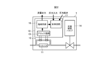
- FIG. 2 shows a configuration diagram of the pressure control device 1.
- the pressure control device 1 includes a bypass 11, a flow rate sensor 12, a control unit 13, and a flow rate control valve 14 that is an electromagnetic valve.
- the control unit 13 includes a bridge circuit 15, an amplifier circuit 16, and a control circuit 17.
- the gas flowing into the pressure control device 1 is diverted to the bypass 11 and the flow sensor 12 at a predetermined flow rate ratio.
- the two coils of the flow sensor 12 constitute a part of the bridge circuit 15.
- the amplifier circuit 16 amplifies the signal related to the temperature difference detected by the bridge circuit 15 and outputs the amplified signal as a flow rate signal (for example, 0 to 5 VDC).
- the flow rate signal is also output to the control circuit 17.
- FIG. 3 shows a block diagram of the flow control valve 14 and the control circuit 17.
- control circuit 17 includes two level conversion circuits 18 and 19, a frequency characteristic correction circuit 20, a comparison circuit 21, and a valve drive circuit 22.
- the level conversion circuits 18 and 19 are a pressure setting signal (for example, 0 to 10 VDC) indicating the set pressure value of the chamber 3 inputted from the outside, and a pressure signal (for example, indicating the pressure value detected by the pressure sensor 4) 0 to 10 VDC) is a circuit for amplifying or attenuating in order to accurately compare with the comparison circuit 21.
- the frequency characteristic correction circuit 20 is a filter circuit using an operational amplifier, and corrects the pressure signal detected by the pressure sensor 4 to raise the low frequency.
- the comparison circuit 21 compares the pressure signal after frequency correction and the set pressure signal, and outputs a difference signal indicating the difference to the valve drive circuit 22.
- the valve drive circuit 22 controls the opening degree of the flow control valve 14 based on the difference signal so that the pressure in the chamber 3 is constant.
- FIG. 4 shows the behavior of the detected pressure signal, the corrected pressure signal, the pressure setting signal, and the valve drive signal when the control of the pressure control system 10 is started.
- the detected pressure signal detected by the pressure sensor 4 is indicated by a solid line
- the corrected pressure signal after correction is indicated by a one-dot chain line
- the pressure setting signal is indicated by a dotted line
- the valve drive signal is indicated by a solid line.
- the dry pump 6 is driven to suck the gas in the chamber 3 with a constant suction force.
- the detected pressure signal decreases at a constant rate.
- the frequency characteristic correction circuit 20 performs frequency characteristic correction on the detected pressure signal.
- the frequency characteristic correction circuit 20 having a proper frequency characteristic.
- the horizontal axis represents frequency and the vertical axis represents voltage.
- the frequency characteristic curve of FIG. 5 has a peak at about 10 Hz corresponding to a predetermined frequency, and the voltage gradually increases from 1.0 V up to 10 Hz, and at a frequency higher than 10 Hz, the voltage decreases linearly. Yes.
- the peak position (predetermined frequency) of the frequency characteristic curve is based on the relationship between the flow rate of the gas flowing through the pipe 7 and the volume of the chamber 3 and / or the length of the pipe 7 between the pressure control device 1 and the chamber 3. It is determined.
- the corrected pressure signal is smaller than the detected pressure signal.
- the frequency characteristic correction circuit 20 corrects the detected pressure signal so as to raise a predetermined frequency component, and as a result, the detected pressure signal is corrected so as to approach the set pressure signal.
- the comparison circuit 21 compares the corrected pressure signal with the pressure setting signal. When the corrected pressure signal becomes smaller than the pressure setting signal (P1 in FIG. 4), the valve drive circuit 22 And the flow control valve 14 is opened. Thereby, gas is supplied to the chamber 3.
- the detected pressure signal becomes equal to the pressure setting signal, and the inclination thereof changes. Due to this change, the correction pressure signal rapidly increases but immediately decreases, and the correction pressure signal becomes substantially equal to the pressure setting signal.
- the frequency characteristic correction circuit 20 corrects the detected pressure signal so as to have a peak at a predetermined frequency and raise a component of the predetermined frequency of the detected pressure signal. Thereby, the time which the flow control valve 14 becomes an open state can be advanced. Therefore, since the gas can be supplied into the chamber 3 when the detected pressure and the set pressure are substantially equal, the volume of the chamber 3 is large with respect to the control flow rate of the gas, or the pressure control device 1 and the chamber Even when the pipe 7 between the two is long, the pressure in the chamber 3 does not move up and down, and the pressure can be kept constant.
- the predetermined frequency is determined based on the relationship between the flow rate of the gas flowing through the pipe 7 and the volume of the chamber 3 and / or the length of the pipe between the chamber 3 and the pressure control device 1, the detected pressure is determined. Appropriate correction can be performed on the signal.
- the detected pressure signal shows a larger value than the set pressure signal and changes so as to decrease
- the detected pressure signal is corrected by the frequency characteristic correcting means 20 so that the value becomes smaller.
- the circuit provided in the pressure control device 1 may be either an analog circuit or a digital circuit.
- the pressure control target in the above embodiment is the chamber 3, but it may be a pressure vessel or the like.
Landscapes
- Physics & Mathematics (AREA)
- General Physics & Mathematics (AREA)
- Engineering & Computer Science (AREA)
- Automation & Control Theory (AREA)
- Fluid Mechanics (AREA)
- Control Of Fluid Pressure (AREA)
- Flow Control (AREA)
Abstract
Description
Claims (4)
- 被圧力制御対象内を設定圧力に保つ圧力制御装置であって、
圧力センサにより検出された被圧力制御対象内の圧力を示す圧力信号を、前記設定圧力を示す設定圧力信号に近づくように補正する補正手段と、
補正された前記圧力信号と、前記設定圧力信号とを比較する比較手段と、
前記比較手段による比較結果に基づき流量制御バルブの開閉を制御するバルブ駆動手段と、を備え、
前記補正手段は、フィルタ回路であり、その周波数特性は、所定の周波数でピークを有し、前記圧力信号の前記所定の周波数の成分を持ち上げるように、前記圧力信号を補正する、圧力制御装置。 - 前記所定の周波数は、前記配管のガスの流量と前記チャンバの容積との関係、および/または前記チャンバと前記圧力制御装置との間の配管の長さに基づき決定される、請求項1の圧力制御装置。
- 前記圧力信号が、前記設定圧力信号よりも大きな値を示し、かつ減少するように変化しているときは、前記圧力信号は、前記補正手段により、その値が小さくなるように補正される、請求項1または請求項2の圧力制御装置。
- 前記圧力信号が、前記設定圧力信号よりも小さな値を示し、かつ増加するように変化しているときは、前記圧力信号は、前記補正手段により、その値が大きくなるように補正される、請求項1または請求項2の圧力制御装置。
Priority Applications (5)
| Application Number | Priority Date | Filing Date | Title |
|---|---|---|---|
| KR1020177024692A KR101966720B1 (ko) | 2015-02-26 | 2016-01-06 | 압력 제어 장치 |
| CN201680003808.2A CN107003684B (zh) | 2015-02-26 | 2016-01-06 | 压力控制装置 |
| SG11201706884WA SG11201706884WA (en) | 2015-02-26 | 2016-01-06 | Pressure control device |
| IL254072A IL254072B (en) | 2015-02-26 | 2017-08-20 | Pressure control device |
| US15/686,981 US10520958B2 (en) | 2015-02-26 | 2017-08-25 | Pressure control device |
Applications Claiming Priority (2)
| Application Number | Priority Date | Filing Date | Title |
|---|---|---|---|
| JP2015-036113 | 2015-02-26 | ||
| JP2015036113A JP6475516B2 (ja) | 2015-02-26 | 2015-02-26 | 圧力制御装置 |
Related Child Applications (1)
| Application Number | Title | Priority Date | Filing Date |
|---|---|---|---|
| US15/686,981 Continuation US10520958B2 (en) | 2015-02-26 | 2017-08-25 | Pressure control device |
Publications (1)
| Publication Number | Publication Date |
|---|---|
| WO2016136282A1 true WO2016136282A1 (ja) | 2016-09-01 |
Family
ID=56788273
Family Applications (1)
| Application Number | Title | Priority Date | Filing Date |
|---|---|---|---|
| PCT/JP2016/050253 Ceased WO2016136282A1 (ja) | 2015-02-26 | 2016-01-06 | 圧力制御装置 |
Country Status (8)
| Country | Link |
|---|---|
| US (1) | US10520958B2 (ja) |
| JP (1) | JP6475516B2 (ja) |
| KR (1) | KR101966720B1 (ja) |
| CN (1) | CN107003684B (ja) |
| IL (1) | IL254072B (ja) |
| SG (1) | SG11201706884WA (ja) |
| TW (1) | TWI575347B (ja) |
| WO (1) | WO2016136282A1 (ja) |
Cited By (1)
| Publication number | Priority date | Publication date | Assignee | Title |
|---|---|---|---|---|
| US10520958B2 (en) | 2015-02-26 | 2019-12-31 | Fujikin Incorporated | Pressure control device |
Families Citing this family (3)
| Publication number | Priority date | Publication date | Assignee | Title |
|---|---|---|---|---|
| JP6706121B2 (ja) * | 2016-03-30 | 2020-06-03 | 株式会社フジキン | 圧力制御装置および圧力制御システム |
| CN107422754B (zh) * | 2017-09-01 | 2023-11-14 | 中国人民解放军军事科学院军事医学研究院 | 一种微量气体流速控制装置及控制方法 |
| TWI755704B (zh) * | 2019-05-14 | 2022-02-21 | 日商富士金股份有限公司 | 流量控制裝置、流量控制方法、流量控制裝置的控制程式 |
Citations (2)
| Publication number | Priority date | Publication date | Assignee | Title |
|---|---|---|---|---|
| JP2006528765A (ja) * | 2003-07-22 | 2006-12-21 | コンティ テミック マイクロエレクトロニック ゲゼルシャフト ミット ベシュレンクテル ハフツング | 圧力を測定する方法及び装置 |
| JP4298025B2 (ja) * | 1998-03-25 | 2009-07-15 | シーケーディ株式会社 | 真空圧力制御システム |
Family Cites Families (19)
| Publication number | Priority date | Publication date | Assignee | Title |
|---|---|---|---|---|
| US3812456A (en) * | 1956-04-20 | 1974-05-21 | Us Navy | A hydro-acoustic filter |
| CH638869A5 (de) * | 1979-03-14 | 1983-10-14 | Bbc Brown Boveri & Cie | Verfahren zur foerderung und steuerung des bypassluftstromes bei aufgeladenen verbrennungskraftmaschinen und verbrennungskraftmaschine zur ausfuehrung des verfahrens. |
| JPS6165127A (ja) * | 1984-09-07 | 1986-04-03 | Hitachi Ltd | 圧力信号の処理装置 |
| JPH03291706A (ja) * | 1990-04-09 | 1991-12-20 | Seiko Instr Inc | ワイドレンジ圧力制御システム |
| JP3586075B2 (ja) * | 1997-08-15 | 2004-11-10 | 忠弘 大見 | 圧力式流量制御装置 |
| US7010136B1 (en) * | 1999-02-17 | 2006-03-07 | Micro Ear Technology, Inc. | Resonant response matching circuit for hearing aid |
| EP1195511A1 (en) * | 1999-06-15 | 2002-04-10 | Hitachi, Ltd. | Air flow measuring device formed integrally with electronically controlled throttle body |
| WO2004109420A1 (ja) * | 2003-06-09 | 2004-12-16 | Ckd Corporation | 相対的圧力制御システム及び相対的流量制御システム |
| JP3863505B2 (ja) * | 2003-06-20 | 2006-12-27 | 忠弘 大見 | 圧力センサ及び圧力制御装置並びに圧力式流量制御装置の自動零点補正装置 |
| JP4399227B2 (ja) * | 2003-10-06 | 2010-01-13 | 株式会社フジキン | チャンバの内圧制御装置及び内圧被制御式チャンバ |
| US7155319B2 (en) * | 2005-02-23 | 2006-12-26 | Applied Materials, Inc. | Closed loop control on liquid delivery system ECP slim cell |
| JP4142704B2 (ja) * | 2006-08-17 | 2008-09-03 | レール・リキード−ソシエテ・アノニム・プール・レテュード・エ・レクスプロワタシオン・デ・プロセデ・ジョルジュ・クロード | スタナン気体供給システム |
| CN201199236Y (zh) * | 2008-04-30 | 2009-02-25 | 刘庆杰 | 轻烃燃气在线热值分析装置 |
| US8477957B2 (en) * | 2009-04-15 | 2013-07-02 | Nokia Corporation | Apparatus, method and computer program |
| CN102072795B (zh) * | 2009-11-20 | 2013-07-31 | 昆山双桥传感器测控技术有限公司 | 压阻式高频高温动态压力传感器 |
| KR20120093788A (ko) * | 2011-02-15 | 2012-08-23 | 가부시키가이샤 호리바 에스텍 | 유체제어장치 및 압력제어장치 |
| JP6061696B2 (ja) * | 2013-01-23 | 2017-01-18 | 西部電機株式会社 | バルブアクチュエータ及びバルブ装置並びにバルブアクチュエータの制御方法 |
| CN103277876B (zh) * | 2013-06-24 | 2016-03-23 | 苏州翔箭智能科技有限公司 | 空调系统中的电子膨胀阀的控制方法 |
| JP6475516B2 (ja) | 2015-02-26 | 2019-02-27 | 株式会社フジキン | 圧力制御装置 |
-
2015
- 2015-02-26 JP JP2015036113A patent/JP6475516B2/ja active Active
-
2016
- 2016-01-06 WO PCT/JP2016/050253 patent/WO2016136282A1/ja not_active Ceased
- 2016-01-06 SG SG11201706884WA patent/SG11201706884WA/en unknown
- 2016-01-06 CN CN201680003808.2A patent/CN107003684B/zh not_active Expired - Fee Related
- 2016-01-06 KR KR1020177024692A patent/KR101966720B1/ko active Active
- 2016-01-07 TW TW105100392A patent/TWI575347B/zh active
-
2017
- 2017-08-20 IL IL254072A patent/IL254072B/en active IP Right Grant
- 2017-08-25 US US15/686,981 patent/US10520958B2/en active Active
Patent Citations (2)
| Publication number | Priority date | Publication date | Assignee | Title |
|---|---|---|---|---|
| JP4298025B2 (ja) * | 1998-03-25 | 2009-07-15 | シーケーディ株式会社 | 真空圧力制御システム |
| JP2006528765A (ja) * | 2003-07-22 | 2006-12-21 | コンティ テミック マイクロエレクトロニック ゲゼルシャフト ミット ベシュレンクテル ハフツング | 圧力を測定する方法及び装置 |
Cited By (1)
| Publication number | Priority date | Publication date | Assignee | Title |
|---|---|---|---|---|
| US10520958B2 (en) | 2015-02-26 | 2019-12-31 | Fujikin Incorporated | Pressure control device |
Also Published As
| Publication number | Publication date |
|---|---|
| SG11201706884WA (en) | 2017-10-30 |
| TWI575347B (zh) | 2017-03-21 |
| CN107003684A (zh) | 2017-08-01 |
| US10520958B2 (en) | 2019-12-31 |
| KR101966720B1 (ko) | 2019-08-27 |
| IL254072B (en) | 2021-06-30 |
| TW201642064A (zh) | 2016-12-01 |
| CN107003684B (zh) | 2020-08-14 |
| US20170351274A1 (en) | 2017-12-07 |
| JP6475516B2 (ja) | 2019-02-27 |
| KR20170113632A (ko) | 2017-10-12 |
| JP2016157362A (ja) | 2016-09-01 |
| IL254072A0 (en) | 2017-10-31 |
Similar Documents
| Publication | Publication Date | Title |
|---|---|---|
| JP6475516B2 (ja) | 圧力制御装置 | |
| JP2008529472A5 (ja) | ||
| US20160018828A1 (en) | Pressure-based mass flow controller with reverse flow mode for fast bleed down | |
| JP2015510722A5 (ja) | ||
| DK2222215T3 (da) | Indretning til styring eller regulering af en støvsugers motoreffekt. | |
| TWI641937B (zh) | 壓力控制裝置及壓力控制系統 | |
| CN103125012A (zh) | 基板处理系统 | |
| FR2932394B1 (fr) | Procede de determination du niveau de colmatage de filtres a air | |
| JP2004332741A (ja) | ポンプ速度および調整弁の変化と、不活性気体の噴射とによるプロセスチャンバ内の圧力制御 | |
| JP6840093B2 (ja) | 電力供給システムの増幅段の出力量を調整するための電力供給システムおよび方法 | |
| US12123760B2 (en) | Flow rate control device, flow rate control method, control program for flow rate control device | |
| JP2012078049A (ja) | 室圧コントロールシステム | |
| JP2016514324A5 (ja) | ||
| JP2015210035A (ja) | 炉内圧力調節装置及び炉内圧力調節方法 | |
| JP2012047380A (ja) | 室圧コントロールシステム | |
| JPH06266446A (ja) | 真空室の圧力制御装置 | |
| JP2001318720A (ja) | 温度制御方法及び装置 | |
| JP6450990B2 (ja) | 圧縮機設備、これを備えるガスタービンプラント、及び圧縮機設備の制御方法 | |
| JPWO2021044178A5 (ja) | ||
| JPH0679159A (ja) | 真空室用ガス導入装置 | |
| JPS63104113A (ja) | 流体流量制御方法 | |
| JP2019078503A (ja) | 囲い式フード装置及びその排気風量制御方法 | |
| KR200146659Y1 (ko) | 반도체 제조용 진공장비의 챔버 벤트장치 | |
| JP2001241841A (ja) | 空気分離装置における圧力制御方法および装置 | |
| US20150280667A1 (en) | Programmable Vacuum Tube Bias Control |
Legal Events
| Date | Code | Title | Description |
|---|---|---|---|
| 121 | Ep: the epo has been informed by wipo that ep was designated in this application |
Ref document number: 16755032 Country of ref document: EP Kind code of ref document: A1 |
|
| WWE | Wipo information: entry into national phase |
Ref document number: 254072 Country of ref document: IL |
|
| NENP | Non-entry into the national phase |
Ref country code: DE |
|
| ENP | Entry into the national phase |
Ref document number: 20177024692 Country of ref document: KR Kind code of ref document: A |
|
| WWE | Wipo information: entry into national phase |
Ref document number: 11201706884W Country of ref document: SG |
|
| 122 | Ep: pct application non-entry in european phase |
Ref document number: 16755032 Country of ref document: EP Kind code of ref document: A1 |