WO2016136050A1 - 血圧測定用カフおよび血圧計 - Google Patents
血圧測定用カフおよび血圧計 Download PDFInfo
- Publication number
- WO2016136050A1 WO2016136050A1 PCT/JP2015/082504 JP2015082504W WO2016136050A1 WO 2016136050 A1 WO2016136050 A1 WO 2016136050A1 JP 2015082504 W JP2015082504 W JP 2015082504W WO 2016136050 A1 WO2016136050 A1 WO 2016136050A1
- Authority
- WO
- WIPO (PCT)
- Prior art keywords
- blood pressure
- clamp portion
- pressure measurement
- clamp
- cuff
- Prior art date
- Legal status (The legal status is an assumption and is not a legal conclusion. Google has not performed a legal analysis and makes no representation as to the accuracy of the status listed.)
- Ceased
Links
Images








Classifications
-
- A—HUMAN NECESSITIES
- A61—MEDICAL OR VETERINARY SCIENCE; HYGIENE
- A61B—DIAGNOSIS; SURGERY; IDENTIFICATION
- A61B5/00—Measuring for diagnostic purposes; Identification of persons
- A61B5/02—Detecting, measuring or recording for evaluating the cardiovascular system, e.g. pulse, heart rate, blood pressure or blood flow
- A61B5/021—Measuring pressure in heart or blood vessels
- A61B5/022—Measuring pressure in heart or blood vessels by applying pressure to close blood vessels, e.g. against the skin; Ophthalmodynamometers
-
- A—HUMAN NECESSITIES
- A61—MEDICAL OR VETERINARY SCIENCE; HYGIENE
- A61B—DIAGNOSIS; SURGERY; IDENTIFICATION
- A61B5/00—Measuring for diagnostic purposes; Identification of persons
- A61B5/02—Detecting, measuring or recording for evaluating the cardiovascular system, e.g. pulse, heart rate, blood pressure or blood flow
- A61B5/021—Measuring pressure in heart or blood vessels
- A61B5/02141—Details of apparatus construction, e.g. pump units or housings therefor, cuff pressurising systems, arrangements of fluid conduits or circuits
-
- A—HUMAN NECESSITIES
- A61—MEDICAL OR VETERINARY SCIENCE; HYGIENE
- A61B—DIAGNOSIS; SURGERY; IDENTIFICATION
- A61B5/00—Measuring for diagnostic purposes; Identification of persons
- A61B5/02—Detecting, measuring or recording for evaluating the cardiovascular system, e.g. pulse, heart rate, blood pressure or blood flow
- A61B5/021—Measuring pressure in heart or blood vessels
- A61B5/022—Measuring pressure in heart or blood vessels by applying pressure to close blood vessels, e.g. against the skin; Ophthalmodynamometers
- A61B5/02233—Occluders specially adapted therefor
-
- A—HUMAN NECESSITIES
- A61—MEDICAL OR VETERINARY SCIENCE; HYGIENE
- A61B—DIAGNOSIS; SURGERY; IDENTIFICATION
- A61B5/00—Measuring for diagnostic purposes; Identification of persons
- A61B5/02—Detecting, measuring or recording for evaluating the cardiovascular system, e.g. pulse, heart rate, blood pressure or blood flow
- A61B5/021—Measuring pressure in heart or blood vessels
- A61B5/022—Measuring pressure in heart or blood vessels by applying pressure to close blood vessels, e.g. against the skin; Ophthalmodynamometers
- A61B5/0225—Measuring pressure in heart or blood vessels by applying pressure to close blood vessels, e.g. against the skin; Ophthalmodynamometers the pressure being controlled by electric signals, e.g. derived from Korotkoff sounds
-
- A—HUMAN NECESSITIES
- A61—MEDICAL OR VETERINARY SCIENCE; HYGIENE
- A61B—DIAGNOSIS; SURGERY; IDENTIFICATION
- A61B5/00—Measuring for diagnostic purposes; Identification of persons
- A61B5/02—Detecting, measuring or recording for evaluating the cardiovascular system, e.g. pulse, heart rate, blood pressure or blood flow
- A61B5/024—Measuring pulse rate or heart rate
- A61B5/02416—Measuring pulse rate or heart rate using photoplethysmograph signals, e.g. generated by infrared radiation
- A61B5/02422—Measuring pulse rate or heart rate using photoplethysmograph signals, e.g. generated by infrared radiation within occluders
-
- A—HUMAN NECESSITIES
- A61—MEDICAL OR VETERINARY SCIENCE; HYGIENE
- A61B—DIAGNOSIS; SURGERY; IDENTIFICATION
- A61B5/00—Measuring for diagnostic purposes; Identification of persons
- A61B5/02—Detecting, measuring or recording for evaluating the cardiovascular system, e.g. pulse, heart rate, blood pressure or blood flow
- A61B5/024—Measuring pulse rate or heart rate
- A61B5/02416—Measuring pulse rate or heart rate using photoplethysmograph signals, e.g. generated by infrared radiation
- A61B5/02427—Details of sensor
-
- A—HUMAN NECESSITIES
- A61—MEDICAL OR VETERINARY SCIENCE; HYGIENE
- A61B—DIAGNOSIS; SURGERY; IDENTIFICATION
- A61B5/00—Measuring for diagnostic purposes; Identification of persons
- A61B5/02—Detecting, measuring or recording for evaluating the cardiovascular system, e.g. pulse, heart rate, blood pressure or blood flow
- A61B5/024—Measuring pulse rate or heart rate
- A61B5/0245—Measuring pulse rate or heart rate by using sensing means generating electric signals, i.e. ECG signals
-
- A—HUMAN NECESSITIES
- A61—MEDICAL OR VETERINARY SCIENCE; HYGIENE
- A61B—DIAGNOSIS; SURGERY; IDENTIFICATION
- A61B5/00—Measuring for diagnostic purposes; Identification of persons
- A61B5/02—Detecting, measuring or recording for evaluating the cardiovascular system, e.g. pulse, heart rate, blood pressure or blood flow
- A61B5/02007—Evaluating blood vessel condition, e.g. elasticity, compliance
-
- A—HUMAN NECESSITIES
- A61—MEDICAL OR VETERINARY SCIENCE; HYGIENE
- A61B—DIAGNOSIS; SURGERY; IDENTIFICATION
- A61B5/00—Measuring for diagnostic purposes; Identification of persons
- A61B5/68—Arrangements of detecting, measuring or recording means, e.g. sensors, in relation to patient
- A61B5/6801—Arrangements of detecting, measuring or recording means, e.g. sensors, in relation to patient specially adapted to be attached to or worn on the body surface
- A61B5/6802—Sensor mounted on worn items
- A61B5/681—Wristwatch-type devices
Definitions
- the present invention relates to a blood pressure measurement cuff, and more particularly to a blood pressure measurement cuff having a clamp mechanism that sandwiches a measurement site.
- the present invention relates to a sphygmomanometer equipped with such a blood pressure measurement cuff.
- a hemostasis assisting device for an arm for example, as disclosed in Patent Document 1 (Japanese Utility Model Publication No. 4-51916), a lower fixing plate and a vertical direction provided on the lower fixing plate are provided.
- An adjuster scale that extends, an adjuster portion that is slidable up and down with respect to the adjuster scale, an upper fixing plate that extends parallel to the lower fixing plate from the adjuster portion, and downward from the tip of the upper fixing plate.
- the adjuster portion can be fixed to the adjuster scale by a fixing screw.
- a configuration (this is called a “clamp mechanism”) that sandwiches a site to be measured such as the hemostasis assisting device can also be applied to a blood pressure measurement cuff.
- the hemostasis assisting device has a problem that it takes time since the five operations i) to v) are required to press the arm.
- an object of the present invention is to provide a blood pressure measurement cuff having a clamp mechanism for sandwiching a measurement site, which can be worn with a simple operation.
- the blood pressure measurement cuff of the present invention is A blood pressure measurement cuff having a clamp mechanism that sandwiches a substantially rod-shaped measurement site,
- the clamp mechanism is A first clamp portion having a shape curved along the first half surface so as to press the first half surface side of the outer peripheral surface of the measurement site;
- a second clamp portion having a shape curved along the second half surface so as to press the second half surface side opposite to the first half surface of the outer peripheral surface of the measurement site;
- the slide hole and the slide bar are curved in such a manner that the side close to the other end of the first clamp portion and the second clamp portion is convex.
- one “end portion” of the first clamp portion and one “end portion” of the second clamp portion refer to a portion of a certain range including an edge.
- the “other end portion” of the first clamp portion and the second clamp portion refers to an end portion on the opposite side to the “one end portion” of both end portions in the circumferential direction.
- the “sliding” of the slide bar relative to the slide hole is relative. Contrary to the above, it can be said that the slide hole (that is, the first clamp portion) slides with respect to the slide rod.
- the blood pressure measurement cuff according to the present invention is attached to the measurement site by the following operation. First, between the first clamp part and the second clamp part, an open state (the slide hole is located on the tip side of the slide bar, the first clamp part 11M and the second clamp part 12M Between the two). (A) First, a site to be measured is disposed between the first clamp portion and the second clamp portion. (B) Next, the first clamp portion and the second clamp portion are moved by sliding the slide bar with respect to the slide hole in a direction to close the space between the first clamp portion and the second clamp portion. The measurement site is sandwiched between the two (the state in which the measurement site is clamped in this way is referred to as the “mounted state”). The blood pressure measurement cuff is attached to the measurement site by two operations, the placement operation (a) and the close operation (b). Therefore, as compared with the conventional example (requiring five operations), the blood pressure measurement cuff can be attached with a simple operation.
- a fluid bag provided along the inner peripheral surface of the first clamp portion is pressurized for blood pressure measurement, and the inner peripheral surface of the first clamp portion and the inner portion of the second clamp portion are pressed. Even if a force for opening relative to the peripheral surface is applied, a moment is applied from the slide hole to the slide bar, and the frictional force increases. As a result, the first clamp portion is not easily opened with respect to the second clamp portion (and the measurement site), and the mounting state is maintained.
- the slide hole and the slide bar are curved in such a manner that the side close to the other end of the first clamp portion and the second clamp portion is convex. Therefore, in the open state, the gap between the other end of the first clamp portion and the other end of the second clamp portion is smaller than when the slide hole and the slide bar are straight. It is wide open. As a result, the placement operation (a), that is, the operation of placing the measurement site between the first clamp portion and the second clamp portion is facilitated.
- the blood pressure measurement cuff is removed from the wearing state by the following operation after blood pressure measurement (an operation for blood pressure measurement described later is (c)).
- the slide rod is slid with respect to the slide hole in a direction to open between the first clamp part and the second clamp part, and between the first clamp part and the second clamp part. Open.
- E Next, the part to be measured is removed from between the first clamp part and the second clamp part.
- the blood pressure measurement cuff Since there is friction between the slide hole and the slide bar, the blood pressure measurement cuff is opened between the first clamp portion 11M and the second clamp portion 12M (open state). ) Is easy to store. However, the blood pressure measurement cuff may be stored in a state where the space between the first clamp portion and the second clamp portion is closed (closed state). In that case, when using the blood pressure measurement cuff, an operation of opening between the first clamp portion and the second clamp portion is added before the placing operation (a).
- a fluid bag to be pressurized at the time of blood pressure measurement is provided along one or both of the inner peripheral surface of the first clamp portion and the inner peripheral surface of the second clamp portion. It is characterized by.
- the fluid bag is pressurized at the time of blood pressure measurement in the mounted state. Thereby, the artery passing through the measurement site is compressed, and blood pressure measurement is performed smoothly.
- a first pressing region for applying a finger is formed adjacent to the slide hole on the outer peripheral surface side of the one end portion of the first clamp portion, A second pressing region for applying a finger is formed at a position corresponding to the first pressing region on the outer peripheral surface side of the one end portion of the second clamp portion.
- the measurement site belongs to the left half of the measurement subject (for example, the left wrist or the upper left arm).
- the slide hole and the slide bar are close to the center of the body of the measurement subject around the measurement site during the placement operation (a). In this case, it is arranged on the side closer to the right hand.
- the measurement subject sandwiches the first pressing area and the second pressing area with the thumb of the right hand and the other finger so as to approach each other, whereby the first clamp part and the second clamp part are Can be closed.
- the first pressing area is formed adjacent to the slide hole
- the second pressing area is formed at a position corresponding to the first pressing area, so that the slide hole is the slide bar.
- the pressing force applied to is relatively small.
- the pressing force that the slide bar applies to the slide hole is relatively small. Therefore, the frictional force between the slide hole and the slide bar is also relatively small.
- the measurement subject can easily close the space between the first clamp portion and the second clamp portion. That is, the closing operation (b) can be easily performed with the right hand (one hand).
- a third pressing area for applying a finger is formed at the tip of the slide bar, A fourth pressing region for applying a finger is formed adjacent to the slide hole on the inner peripheral surface side of the one end portion of the first clamp portion.
- the measurement subject approaches the third pressing region and the fourth pressing region with the thumb and other fingers of one hand. By sandwiching in this manner, the space between the first clamp portion and the second clamp portion can be opened.
- the third pressing region is formed at the tip of the slide bar and the fourth pressing region is formed adjacent to the slide hole, the pressing force applied to the slide rod by the slide hole Is relatively small. Therefore, the frictional force between the slide hole and the slide bar is also relatively small.
- the person to be measured can easily open the space between the first clamp portion and the second clamp portion. That is, the opening operation (d) can be easily performed with one hand.
- the cross section perpendicular to the penetrating direction of the slide hole is substantially rectangular, A blood pressure measurement cuff, wherein a cross-sectional shape perpendicular to a direction in which the slide bar extends substantially matches a cross-sectional shape of the slide hole.
- the phrase “substantially rectangular shape” of the slide hole means not only a true rectangle but also a case where the slide hole is slightly deformed due to manufacturing variation or the like.
- the fact that the cross-sectional shape of the slide bar is “substantially coincident” with the cross-sectional shape of the slide hole means that not only a true rectangle but also a corner portion (in the cross section) of the slide bar is chamfered It is meant to include the case where it is formed and the case where it is slightly deformed due to manufacturing variations.
- the first clamp portion and the second clamp along the plane including the curved slide bar during the closing operation (b) and the opening operation (d).
- the part moves (slides). That is, since the slide bar having a rectangular cross section is fitted into the slide hole having a rectangular cross section, the first clamp portion is restricted from rotating around the slide bar. Therefore, even if the above operations (a) to (e) are repeated, after the closing operation (b), the first clamp portion and the second clamp portion always face each other, and the measured object The part can be pressed.
- the second edge closer to the other end of the first clamp part is the first clamp part.
- the third edge far from the other end of the first clamp part is the first clamp part. It is characterized in that it is located farther from the second clamp part in the penetration direction than the fourth edge closer to the other end.
- the blood pressure measurement cuff in the mounted state, for example, a fluid bag provided along the inner peripheral surface of the first clamp portion is pressurized to measure the blood pressure, and the first clamp portion is pressed.
- a force in a relatively opening direction is applied between the inner peripheral surface and the inner peripheral surface of the second clamp portion, the pressing force applied to the slide rod by the inner surface of the slide hole increases.
- the inner peripheral surface of the first clamp portion is a force point and the second edge of the slide hole is a fulcrum
- the third edge of the slide hole corresponds to an action point.
- the second edge is closer to the second clamp part in the penetration direction than the first edge, and / or the third edge is the above-mentioned It exists in the position far from the said 2nd clamp part regarding the said penetration direction rather than a 4th edge. That is, the distance between the second edge as the fulcrum and the third edge as the action point (moment arm length) is relatively short. Therefore, the pressing force that acts on the third edge (and the second edge that is a fulcrum) that is the point of action increases. As a result, the frictional force acting between the slide hole and the slide bar is increased. As a result, the first clamp portion is more difficult to open with respect to the second clamp portion (and the measurement site), and the mounting state is reliably maintained.
- the cross sections of the first edge and the fourth edge are rounded to reduce friction
- Cross sections of the second edge and the third edge are formed at right angles or acute angles so as to increase friction.
- the pressing force applied to the slide rod by the inner surface of the slide hole mainly acts on the first edge and the fourth edge.
- the cross sections of the first edge and the fourth edge are rounded so as to reduce friction. Therefore, the closing operation (b) is more easily performed.
- a fluid bag provided along the inner peripheral surface of the first clamp portion is pressurized for blood pressure measurement, and the inner peripheral surface of the first clamp portion and the second clamp are pressed.
- the pressing force applied to the slide bar by the inner surface of the slide hole is mainly applied to the second edge and the third edge. work.
- the cross sections of the second edge and the third edge are formed at right angles or acute angles so as to increase friction. Therefore, the first clamp part is more difficult to open with respect to the second clamp part (and the measurement site), and the mounting state is reliably maintained.
- the circumferential dimension of the second clamp part is set smaller than the circumferential dimension of the first clamp part
- the penetration direction of the slide hole is inclined outward with respect to the circumferential direction from the one end portion of the first clamp portion as it approaches the inner peripheral surface side from the outer peripheral surface side of the first clamp portion.
- the first dimension of the first clamp portion is completely the same as the first half surface of the thick measurement site. Set to the dimension to cover. It is assumed that an artery to be compressed passes through the first half. In that case, the first half surface of the thick part to be measured is disposed to face the inner peripheral surface of the first clamp portion during the placing operation (a). In addition, since the circumferential dimension of the second clamp portion is smaller than the circumferential dimension of the first clamp portion, the second portion of the thick portion to be measured is attached in the mounted state after the closing operation (b).
- a portion of the half surface of the first clamp portion that is far from the slide rod may protrude outward from the other end of the second clamp portion, but the fluid is substantially entirely distributed along the inner peripheral surface of the first clamp portion. If a bag is provided, blood pressure measurement will not be hindered.
- the first half surface of the thin measurement site is placed on the inner peripheral surface of the first clamp portion. Place them facing each other.
- the closing operation (b) as the second clamp part approaches relatively to the first clamp part, the second clamp part becomes the one end of the first clamp part.
- the said thin to-be-measured part can be reliably clamped between the said 1st clamp part and the said 2nd clamp part.
- a fluid bag to be pressurized at the time of blood pressure measurement is provided substantially throughout the inner peripheral surface of the first clamp portion, An element is provided on the inner peripheral surface side of the portion adjacent to the one end portion of the second clamp portion to restrict expansion of the opposed portion of the fluid bag.
- the end of the fluid bag close to the slide bar is connected to the second clamp part. It may swell greatly toward the blood pressure, which may hinder blood pressure measurement.
- an element that regulates the expansion of the opposing portion of the fluid bag is provided on the inner peripheral surface side of the portion adjacent to the one end portion of the second clamp portion. Is provided. Therefore, the element regulates the expansion of the opposing part of the fluid bag. As a result, blood pressure measurement is performed smoothly with high accuracy.
- the blood pressure measurement cuff includes an elastic member that applies tension between the one end of the first clamp portion and the one end of the second clamp portion. .
- the first clamp portion and the second clamp portion are easily closed by the tension of the elastic member during the closing operation.
- the tension of the elastic member is set to be larger than the frictional force between the slide hole and the slide bar, the person to be measured can move the first clamp portion and the first clamp during the closing operation. There is no need to apply an external force to close the space between the two clamp parts.
- the inner peripheral surface (or fluid bag) of the first clamp portion and the inner peripheral surface of the second clamp portion are in close contact with the measurement site. Therefore, blood pressure measurement is performed accurately and smoothly.
- the blood pressure measurement cuff includes a latch mechanism that maintains an open state between the first clamp portion and the second clamp portion.
- the latch mechanism maintains an open state between the first clamp portion and the second clamp portion. Therefore, the person to be measured can perform the above-described arrangement operation while the space between the first clamp portion and the second clamp portion is maintained in the open state. Note that the maintenance of the open state by the latch mechanism can be released after the placing operation.
- the sphygmomanometer of the present invention includes the blood pressure measurement cuff of the present invention and a main body incorporating an element for blood pressure measurement.
- the blood pressure measurement cuff can be attached by a simple operation as described above. Therefore, blood pressure measurement is performed smoothly.
- the main body is integrally attached to the blood pressure measurement cuff so as to cover the outer peripheral surface of the first clamp portion,
- An operation switch for inputting a blood pressure measurement start instruction is provided in a region adjacent to the slide hole of the first clamp portion of the outer surface of the main body,
- a second pressing region for applying a finger is formed at a position corresponding to the operation switch on an outer peripheral surface side of the one end portion of the second clamp portion of the cuff.
- the measurement site belongs to the left half of the measurement subject (for example, the left wrist or the upper left arm).
- the slide hole and the slide bar are located near the center of the body of the person to be measured, If it is placed on the side closer to the right hand.
- an operation switch for inputting a blood pressure measurement start instruction is provided in a region adjacent to the slide hole of the first clamp portion on the outer surface of the main body. Therefore, the person to be measured sandwiches the operation switch and the second pressing area with the thumb of the right hand and the other finger so as to approach each other, so that the gap between the first clamp part and the second clamp part is obtained. It can be easily closed.
- the closing operation (b) can be easily performed with one hand. Further, by performing the closing operation (b), the measurement start instruction operation (c), that is, the operation switch provided on the main body is pressed to input the blood pressure measurement start instruction to the main body. it can. That is, the closing operation (b) and the measurement start instruction operation (c) can be performed simultaneously. Therefore, blood pressure can be measured with a simple operation.
- the blood pressure measurement cuff of the present invention can be attached by a simple operation.
- the blood pressure measurement cuff can be attached by a simple operation.
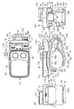
- FIG. 2C is a diagram showing the sphygmomanometer of FIG. 1 as viewed from the front
- FIG. 2A is a diagram of the sphygmomanometer of FIG. 2C as viewed from above
- FIG. 2C is a diagram showing the sphygmomanometer of FIG. 2C viewed from the left side
- FIG. 2D is a diagram showing the sphygmomanometer of FIG. 2C viewed from the right side.
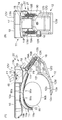
- FIG. 4 (C) is a view showing the blood pressure monitor of FIG. 3 as viewed from the front
- FIG. 4 (A) is a view showing what is shown in FIG. 4 (C) from the top
- FIG. 4C is a diagram showing a view of what is shown in FIG. 4C from the left side
- FIG. 4D is a diagram showing a view of what is shown in FIG. 4C from the right side.
- FIG. 12A shows an operation of opening the blood pressure measurement cuff in FIG. 11 and a left wrist as a measurement site between the first clamp portion and the second clamp portion of the blood pressure measurement cuff. It is a figure which shows operation.
- FIG. 12 (B) is a diagram showing the one shown in FIG. 12 (A) as viewed from the right side.
- FIG. 13A is a perspective view showing a state (wearing state) in which a sphygmomanometer including the blood pressure measurement cuff in FIG. 11 is attached to the left wrist as a part to be measured.
- FIG. 13 (B) is a diagram showing the one shown in FIG. 13 (A) as viewed from the right side. It is a figure which shows the block configuration of the said blood pressure meter. It is a figure which shows the flow of the blood pressure measurement by the said blood pressure meter.
- FIG. 1 shows the appearance of a sphygmomanometer 1 provided with a blood pressure measurement cuff (in an open state) 20 according to an embodiment of the present invention as viewed obliquely.
- 2 (C) shows the sphygmomanometer 1 from the front
- FIG. 2 (A) shows the sphygmomanometer 1 from above
- FIG. 2 (B) shows the sphygmomanometer 1 viewed from the left side
- FIG. 2D shows the sphygmomanometer 1 as viewed from the right side.
- the sphygmomanometer 1 includes a blood pressure measurement cuff (hereinafter simply referred to as “cuff”) 20 having a clamp mechanism 21 and a main body 10 incorporating an element for blood pressure measurement. It is prepared as one.
- the sphygmomanometer 1 is scheduled to be attached to the left wrist 90 as a substantially rod-shaped measurement site.
- the outer peripheral surface of the left wrist 90 includes a half surface 90a on the palm side as a first half surface and a half surface 90b on the back side of the hand as a second half surface corresponding to the opposite side.
- arteries 90u and 90v to be compressed in blood pressure measurement pass.
- 4A to 4D show the components shown in FIG. 3 corresponding to FIGS. 2A to 2D, respectively.
- the cuff 20 includes an upper member 11 to which the main body 10 is integrally attached, and a lower member 12 provided to be slidable with respect to the upper member 11. It has.
- upper member and “lower member” are names for convenience of explanation, and in practice, the upper member may be in a lower position and the lower member may be in an upper position. The same applies to the “left end” and “right end”, which will be described later. In practice, the left end may be right and the right end may be left.
- the upper member 11 has a first clamp portion 11M having a shape curved in the circumferential direction X1 along the palm-side half surface 90a of the left wrist 90, and one end portion in the circumferential direction X1 of the first clamp portion 11M (see FIG. 1 and a right end portion in FIG. 2 (C)) 11f and a block portion 11N formed integrally.
- the first clamp portion 11M is generally formed in a plate shape having a substantially arc-shaped cross section that is partially cut out in the circumferential direction of the short cylinder.
- a slide hole 13 is formed in the block portion 11N so as to penetrate in a direction Y (this is referred to as a “penetration direction”) that intersects the circumferential direction X1.
- a cross section perpendicular to the penetrating direction Y of the slide hole 13 has a substantially rectangular shape (see particularly FIG. 4A).
- the upper side (outer peripheral surface 11a side) of the block portion 11N is adjacent to the front side of the slide hole 13 and is inclined upward to the right so as to apply a finger.
- a first pressing region 15 is formed.
- the first pressing area 15 displays “CLOSE” (closed).
- a pair of guide portions 11P and 11Q for guiding a slide rod 14 described below is integrally formed so as to extend obliquely to the lower right.
- the lower member 12 has a second clamp portion 12M having a shape curved in the circumferential direction X2 along the half surface 90b on the back side of the left wrist 90, and one end portion in the circumferential direction X2 of the second clamp portion 12M (see FIG. 1 and the right end portion 12f in FIG. 2C) are provided integrally with connecting plate portions 12P and 12Q, a substrate portion 12S, a slide bar 14, and an end plate portion 12V.
- the second clamp portion 12M is formed in a curved plate shape that is partially cut out in the circumferential direction of the short cylinder, similar to the first clamp portion 11M.
- the dimension in the circumferential direction X2 of the second clamp part 12M is set smaller than the dimension in the circumferential direction X1 of the first clamp part 11M.
- the connecting plate portions 12P and 12Q are each formed in a generally flat plate shape, and their tips join together to increase strength.
- the substrate portion 12S has a substantially flat plate shape, and is integrally formed at the leading end of the upper connecting plate portion 12P and the lower connecting plate portion 12Q so as to extend obliquely upward.
- a protrusion 12R is integrally formed on the substrate portion 12S so as to protrude toward the front side.
- the protrusion 12R On the lower side (outer peripheral surface 12a side) of the protrusion 12R, a flat surface for applying a finger inclined upward to the right at a position corresponding to the first pressing region 15 of the upper member 11 in the front-rear (front / back) direction. A second pressing region 16 is formed.
- the protrusion 12R displays “CLOSE” (closed).
- the slide bar 14 is fitted to extend from the board portion 12S to the upper left, more specifically, into the slide hole 13 of the first clamp portion 11M.
- the shape of the cross section perpendicular to the direction in which the slide bar 14 extends is substantially rectangular, and substantially coincides with the shape of the cross section of the slide hole 13. Thereby, the slide bar 14 can slide with friction with respect to the slide hole 13.
- each corner portion 14c of the slide bar 14 is chamfered (in particular, see FIGS. 1 and 3), thereby preventing each corner portion 14c from being caught in the slide hole 13.
- the end plate portion 12 ⁇ / b> V is formed in a block shape having a size larger than the cross-sectional size of the slide hole 13 in the front-rear direction and the left-right direction, and is attached to the tip of the slide bar 14.
- a flat third pressing region 17 that is inclined upward and inclined to the right is formed at a position corresponding to the fourth pressing region 18 of the upper member 11 in the front-rear direction. .
- “OPEN” open
- the slide bar 14 slides relative to the slide hole 13 from the tip side (end plate portion 12V side) to the root side (substrate portion 12S side) or vice versa from the root side to the tip side.
- the cuff 20 is said to be in the “open state” when the slide hole 13 is located on the distal end side of the slide rod 14 and the space between the first clamp portion 11M and the second clamp portion 12M is open. Conversely, when the slide hole 13 is positioned on the base side of the slide bar 14 and the space between the first clamp portion 11M and the second clamp portion 12M is closed, the cuff 20 is in the “closed state”. To tell.
- the first pressing region 15 and the third pressing region 17 are located substantially in the same plane. Thereby, the appearance of the cuff 20 is improved.
- the penetrating direction Y of the slide hole 13 is illustrated to extend outward (ie, vertically) from the upper end of the block portion 11N toward the outer side with respect to the circumferential direction X1 rather than the right end portion 11f of the first clamp portion 11M. (In this example, to the lower right) is tilted outward from the vertical line. Furthermore, the slide hole 13 and the slide bar 14 are convex on the sides close to the other end portions (left end portions in FIGS. 1 and 2C) 11e and 12e of the first clamp portion 11M and the second clamp portion 12M. Curved in a manner.
- the upper member 11 (including the first clamp portion 11M, the block portion 11N, and the guide portions 11P and 11Q) is made of ABS (acrylonitrile butadiene styrene copolymer) resin in this example, and is formed by integral molding.
- ABS acrylonitrile butadiene styrene copolymer
- the second clamp portion 12M, the connecting plate portions 12P and 12Q, the substrate portion 12S, and the slide bar 14 are formed by integral molding.
- a separately prepared end plate portion 12V is fixed to the tip of the slide bar 14 with a screw (not shown).
- Each element 12M, 12P, 12Q, 12S, 14, 12V of the lower member 12 is also made of ABS resin, like the upper member 11.
- a fluid bag 22 to be pressurized at the time of blood pressure measurement is provided over substantially the entire area along the inner peripheral surface 11b of the first clamp portion 11M.
- the fluid bag may be provided along the inner peripheral surface 12b of the second clamp portion 12M.
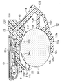
- FIG. 5 shows a cross section of the sphygmomanometer 1 parallel to FIG. 2 (C).
- the third edge 13e3 far from the left end portion 11e of the first clamp portion 11M is the first clamp portion. It is located farther from the second clamp portion 12M in the penetrating direction Y than the fourth edge 13e4 on the side close to the left end 11e of 11M.
- the cross-sections of the first edge 13e1 and the fourth edge 13e4 are rounded to reduce friction.
- the cross sections of the second edge 13e2 and the third edge 13e3 are formed at right angles or acute angles so as to increase friction.
- the main body 10 is integrally mounted on the first clamp portion 11 ⁇ / b> M of the upper member 11. Specifically, a concave groove 10 d is provided on the lower surface 10 b of the main body 10. On the outer peripheral surface 11a of the first clamp portion 11M, a protrusion 11c that fits into the groove 10d of the main body 10 is provided. The concave groove 10d of the main body 10 is fitted and aligned with the protrusion 11c of the first clamp portion 11M, and a fixing means (not shown) is provided with a hook on the first clamp portion 11M side. Are attached integrally with each other.
- the first clamp portion 11M is provided with a communication hole 11o penetrating between the outer peripheral surface 11a side and the inner peripheral surface 11b side at a portion corresponding to the protrusion 11c.
- a pipe passing through the communication hole 11o, pressurizing air is supplied to the fluid bag 22 from a pump (described later) disposed inside the main body 10, and exhaust from the fluid bag 22 is performed. .
- the user of the sphygmomanometer 1 (typically) at the right end of the upper surface (outer surface) 10a of the main body 10, that is, the region adjacent to the slide hole 13 of the first clamp portion 11M.
- a measurement / stop switch 52A for the user to give an instruction to start or stop the measurement is arranged at the front side, that is, at a position corresponding to the second pressing region 16 with respect to the front / rear (front / back) direction.
- a recording call switch 52B for the user to call blood pressure measurement is arranged on the back side.
- a display (in this example, a liquid crystal display element) 50 for displaying blood pressure measurement results and information related to blood pressure is provided in a region other than the operation unit 52 in the upper surface 10 a of the main body 10.
- the sphygmomanometer 1 is attached to the left wrist 90 as a part to be measured by the following operations (a) and (b). First, it is assumed that the first clamp portion 11M and the second clamp portion 12M are in an open state.
- the person to be measured has the slide hole 13 and the slide bar 14 around the left wrist 90 on the side close to the center of the body of the person to be measured, in this case, close to the right hand. Place on the side. Further, the palm-side half surface 90a through which the arteries 90u and 90v of the left wrist 90 pass is directed upward so as to contact the fluid bag 22.
- the slide hole 13 and the slide bar 14 are curved in such a manner that the sides close to the left end portions 11e and 12e of the first clamp portion 11M and the second clamp portion 12M are convex. . Therefore, in the open state, Y2 is greatly opened between the left end portion 11e of the first clamp portion 11M and the left end portion 12e of the second clamp portion 12M as compared with the case where the slide hole 13 and the slide bar 14 are straight. (Y2 is larger than the distance Y1 on the slide bar 14). As a result, the placing operation (a) is facilitated.
- the person to be measured sandwiches the first pressing area 15 and the second pressing area 16 with the thumb of the right hand and another finger so that the first pressing area 15 and the second pressing area 16 approach each other.
- the first pressing region 15 is formed adjacent to the slide hole 13
- the second pressing region 16 is formed at a position corresponding to the first pressing region 15.
- the pressure applied to the slide hole 14 is relatively small, and the pressure applied to the slide hole 13 by the slide bar 14 is relatively small.
- the fourth edge 13e4 corresponds to the action point when the first pressing region 15 is a force point and the first edge 13e1 is a fulcrum.
- the fulcrum A distance L1 between a certain first edge 13e1 and a fourth edge 13e4 that is an action point is relatively long. Therefore, the pressing force acting on the fourth edge 13e4 (and the first edge 13e1) is relatively small.
- the first edge 13e1 corresponds to the action point when the second pressing region 16 is a force point and the fourth edge 13e4 is a fulcrum.
- the distance between the fourth edge 13e4 that is the fulcrum and the first edge 13e1 that is the action point, compared to the distance between the second pressing region 16 that is the power point and the fourth edge 13e4 that is the fulcrum. L1 is relatively long. Therefore, the pressing force acting on the first edge 13e1 (and the fourth edge 13e4) is relatively small. Thereby, the frictional force between the slide hole 13 and the slide bar 14 is also relatively small.
- the frictional force between the slide hole 13 and the slide bar 14 is further reduced.
- the measurement subject can easily close the space between the first clamp portion 11M and the second clamp portion 12M. That is, the closing operation (b) can be easily performed with one hand.
- the sphygmomanometer 1 (cuff 20) is attached to the left wrist 90 by two operations, the operation (a) and the closing operation (b) for arranging as described above. Therefore, as compared with the conventional example (requires five operations), the sphygmomanometer 1 can be mounted with a simple operation.
- the measurement subject performs the following measurement start instruction operation (c). I do.
- a measurement / stop switch 52A as an operation switch provided on the main body 10 is pressed to input a blood pressure measurement start instruction to the main body 10.
- the fluid bag 22 provided along the inner peripheral surface 11b of the first clamp portion 11M is pressurized and blood pressure measurement is performed (the blood pressure measurement flow will be described later).
- the fluid bag 22 provided along the inner peripheral surface 11b of the first clamp portion 11M is pressurized, and the inner peripheral surface 11b of the first clamp portion 11M and The force F3, F4 of the direction which opens relatively between the inner peripheral surface 12b of the 2nd clamp part 12M is added.
- a moment is applied to the slide bar 14 from the slide hole 13 to increase the pressing force, and a moment is applied to the slide hole 13 from the slide bar 14 to increase the pressing force.
- the third edge 13e3 corresponds to an action point.
- it is compared with the distance between the inner peripheral surface 11b of the first clamp portion 11M that is the power point and the second edge 13e2 that is the fulcrum (more precisely, the length of the arm of the moment; the same applies hereinafter in this paragraph).
- the distance L2 between the second edge 13e2 as the fulcrum and the third edge 13e3 as the action point is relatively short.
- the pressing force acting on the third edge 13e3 (and the second edge 13e2) is increased.
- the moment Tr4 that the slide bar 14 gives to the slide hole 13 by the force F4 when the inner peripheral surface 12b of the second clamp portion 12M is a force point and the third edge 13e3 of the slide hole 13 is a fulcrum,
- the two edges 13e2 correspond to the action points.
- the third edge 13e3 as a fulcrum and the second edge 13e2 as an action point are compared to the distance between the inner peripheral surface 12b of the second clamp portion 12M as a force point and the third edge 13e3 as a fulcrum.
- the distance L2 between is relatively short.
- the pressing force acting on the second edge 13e2 (and the third edge 13e3) is increased.
- the second edge 13e2 is closer to the second clamp portion 12M with respect to the penetration direction Y than the first edge 13e1, and the third edge 13e3 is more than the fourth edge 13e4.
- the distance L2 between the second edge 13e2 and the third edge 13e3 is set shorter than the distance L1 between the first edge 13e1 and the fourth edge 13e4. Accordingly, the pressing force acting on the second edge 13e2 and the third edge 13e3 is further increased. As a result, the frictional force acting between the slide hole 13 and the slide bar 14 is increased.
- the cross sections of the second edge 13e2 and the third edge 13e3 are formed at right angles or acute angles, the frictional force between the slide hole 13 and the slide bar 14 is further increased.
- the first clamp portion 11M is difficult to open with respect to the second clamp portion 12M (and the left wrist 90), and the mounting state is reliably maintained.
- This blood pressure monitor 1 is removed by the following operations (d) and (e) after blood pressure measurement.
- the person to be measured sandwiches the third pressing area 17 and the fourth pressing area 18 with the thumb of the right hand and other fingers so that the third pressing area 17 and the fourth pressing area 18 approach each other.
- the third pressing area 17 is formed at the tip of the slide bar 14 and the fourth pressing area 18 is formed adjacent to the slide hole 13
- the pressing force that the slide bar 14 applies to the slide hole 13. Is relatively small, and the pressing force applied to the slide bar 14 by the slide hole 13 is relatively small.
- the fourth edge 13e4 corresponds to an action point.
- the distance between the first edge 13e1 as the fulcrum and the fourth edge 13e4 as the action point is larger than the distance between the third pressing region 17 as the power point and the first edge 13e1 as the fulcrum.
- L1 is relatively long. Therefore, the pressing force acting on the fourth edge 13e4 (and the first edge 13e1) is relatively small.
- the fourth edge 13e4 corresponds to an action point.
- the fulcrum A distance L1 between a certain first edge 13e1 and a fourth edge 13e4 that is an action point is relatively long. Therefore, the pressing force acting on the fourth edge 13e4 (and the first edge 13e1) is relatively small.
- the frictional force between the slide hole 13 and the slide bar 14 is also relatively small.
- the rounds are applied to the cross sections of the first edge 13e1 and the fourth edge 13e4, the frictional force between the slide hole 13 and the slide bar 14 is further reduced.
- the measurement subject can easily open the space between the first clamp portion 11M and the second clamp portion 12M. That is, the opening operation (d) can be easily performed with one hand.
- blood pressure monitor 1 blood pressure can be measured with a simple operation.
- the first clamp portion 11M and the second clamp portion 12M move (slide) along a plane including the curved slide bar 14. ) That is, since the slide bar 14 having a rectangular cross section is fitted in the slide hole 13 having a rectangular cross section, the rotation of the first clamp portion 11M around the slide bar 14 is restricted. Therefore, even if the above operations (a) to (e) are repeated, after the closing operation (b), the first clamp portion 11M and the second clamp portion 12M always face each other in the vertical direction so that the left hand The neck 90 can be pressed.
- a measurement / stop switch 52A as an operation switch is provided at a position corresponding to 16. Therefore, the person to be measured sandwiches the measurement / stop switch 52A and the second holding region 16 with the thumb of the right hand and the other finger so as to approach each other, thereby causing the first clamp portion 11M and the second clamp portion 12M to move.
- the space can be easily closed. That is, the closing operation (b) can be easily performed with one hand.
- the measurement start instruction operation (c) that is, the operation of inputting the blood pressure measurement start instruction to the main body 10 by pressing the measurement / stop switch 52A can be performed.
- the measurement subject can simultaneously perform the closing operation (b) and the measurement start instruction operation (c), and thus can perform blood pressure measurement with a simpler operation.
- the sphygmomanometer 1 Since there is friction between the slide hole 13 and the slide bar 14, the sphygmomanometer 1 is stored with the space between the first clamp portion 11M and the second clamp portion 12M opened (open state). It's easy to do. However, the cuff 20 may be stored in a state where the space between the first clamp portion 11M and the second clamp portion 12M is closed (closed state). In that case, when using the sphygmomanometer 1, an operation of opening the first clamp portion 11M and the second clamp portion 12M is added before the placing operation (a).
- FIG. 9 shows a state in which the sphygmomanometer 1 is attached to the left wrist 91 which is thicker than the left wrist 90 described above.
- the circumferential dimension of the first clamp portion 11M is set to a dimension that completely covers the palm-side half surface 91a of the thick left wrist 91.
- the fluid bag 22 provided over substantially the entire area along the inner peripheral surface 11b of the first clamp portion 11M covers most of the half surface 91a on the palm side of the thick left wrist 91. Therefore, when the fluid bag 22 is pressurized, the arteries 90u and 90v are compressed, and blood pressure measurement is performed smoothly.
- the second clamp part 12M since the circumferential dimension of the second clamp part 12M is smaller than the circumferential dimension of the first clamp part 11M, the lower left part far from the slide bar 14 of the thick left wrist 91 is the second clamp part 12M. Projecting outward from the left end 12e of the. However, since the arteries 90u and 90v to be compressed are present on the half surface 91a on the palm side and not on the half surface 91b on the back side of the hand, there is no problem in blood pressure measurement.
- FIG. 10 shows a state in which the sphygmomanometer 1 is attached to the left wrist 92 that is thinner than the left wrist 90 described above.
- the second clamp portion 12M becomes closer to the first clamp portion 11M.
- the 2nd clamp part 12M will be in the state along the half surface 92b by the side of the back of the hand of the thin left wrist 92.
- FIG. Thereby, the thin left wrist 92 can be reliably clamped between the first clamp portion 11M and the second clamp portion 12M.
- the palm-side half surface 92a of the thin left wrist 92 is held at a position offset from the left end portion 11e in the circumferential direction with respect to the first clamp portion 11M.
- the right end 22x of the fluid bag 22 is not in contact with the left wrist 92 (particularly, the palm-side half surface 92a). Therefore, if there is no contrivance, when the fluid bag 22 is pressurized, the right end portion 22x of the fluid bag 22 swells greatly toward the second clamp portion 12M as shown by a two-dot chain line in FIG. Therefore, there is a possibility that the blood pressure measurement may be hindered.
- the sphygmomanometer 1 targets the thick left wrist 91 to the thin left wrist 92 by moving the second clamp portion 12M to the lower left or upper left relative to the first clamp portion 11M. Blood pressure measurement can be performed smoothly.
- the sphygmomanometer 1 is attached to the measurement site (for example, the left wrist) belonging to the left half, but is not limited thereto.
- the sphygmomanometer 1 may be attached to a measurement site (for example, the right wrist) belonging to the right half.
- the slide hole 13 and the slide bar 14 are arranged around the measurement site on the side close to the center of the body of the measurement subject, in this case, the side close to the left hand.
- the person to be measured easily sandwiches the first holding area 15 and the second holding area 16 with the thumb of the left hand and the other finger, so that the first clamp portion 11M and the second clamp portion 12M are easily interposed. Can be closed.
- the person to be measured easily opens the space between the first clamp portion 11M and the second clamp portion 12M by sandwiching the third pressing region 17 and the fourth pressing region 18 with the left thumb and other fingers. be able to. That is, each operation can be easily performed with the left hand (one hand).
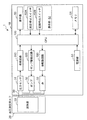
- FIG. 14 shows a schematic block configuration of the sphygmomanometer 1.
- a CPU Central Processing Unit
- a memory 51 as a storage unit, as elements for blood pressure measurement
- a power supply unit 53 a pump 32, a valve 33, and a pressure sensor 31 are incorporated.
- the main body 10 includes an oscillation circuit 310 that converts the output from the pressure sensor 31 into a frequency, a pump drive circuit 320 that drives the pump 32, and a valve drive circuit 330 that drives the valve 33.
- the display 50 includes a display, an indicator, and the like, and displays predetermined information according to a control signal from the CPU 100.
- the measurement / stop switch 52A and the recording call switch 52B included in the operation unit 52 input an operation signal according to an instruction from the user to the CPU 100.
- the memory 51 stores program data for controlling the sphygmomanometer 1, data used for controlling the sphygmomanometer 1, setting data for setting various functions of the sphygmomanometer 1, and blood pressure value measurement results Store data etc.
- the memory 51 is used as a work memory when the program is executed.
- the CPU 100 performs control for driving the pump 32 and the valve 33 in accordance with an operation signal from the operation unit 52 in accordance with a program for controlling the sphygmomanometer 1 stored in the memory 51. Further, the CPU 100 calculates a blood pressure value based on a signal from the pressure sensor 31 and controls the display device 50 and the memory 51.
- the power supply unit 53 supplies power to the CPU 100, the pressure sensor 31, the pump 32, the valve 33, the display 50, the memory 51, the oscillation circuit 310, the pump drive circuit 320, and the valve drive circuit 330.
- the pump 32 supplies air to the fluid bag 22 in order to pressurize the pressure (cuff pressure) in the fluid bag 22 contained in the cuff 20.
- the valve 33 is opened and closed in order to discharge or enclose the air in the fluid bag 22 to control the cuff pressure.
- the pump drive circuit 320 drives the pump 32 based on a control signal given from the CPU 100.
- the valve drive circuit 330 opens and closes the valve 33 based on a control signal given from the CPU 100.
- the pressure sensor 31 and the oscillation circuit 310 function as a pressure detection unit that detects the pressure of the cuff.
- the pressure sensor 31 is, for example, a piezoresistive pressure sensor, and is connected to the fluid bag 22 contained in the pump 32, the valve 33, and the cuff 20 via the cuff air tube 39.
- the oscillation circuit 310 oscillates based on an electrical signal value based on a change in electrical resistance due to the piezoresistive effect from the pressure sensor 31 and outputs a frequency signal having a frequency corresponding to the electrical signal value of the pressure sensor 31 to the CPU 100. Output to.
- a cuff is attached in advance to a measurement site (such as an arm) of a subject, and at the time of measurement, the pump / valve is controlled so that the cuff pressure is higher than the maximum blood pressure and then gradually reduced.
- the cuff pressure is detected by a pressure sensor, and the fluctuation of the arterial volume generated in the artery at the measurement site is extracted as a pulse wave signal.
- systolic blood pressure Systolic Blood Blood Pressure
- diastolic blood pressure Diastolic Blood Blood Pressure
- the blood pressure value of the subject is measured by the CPU 100 by the oscillometric method according to the flow of FIG.
- the sphygmomanometer 1 starts blood pressure measurement as shown in FIG.
- the CPU 100 initializes the processing memory area and outputs a control signal to the valve drive circuit 330.
- the valve drive circuit 330 opens the valve 33 and exhausts the air in the fluid bag 22 of the cuff 20. Subsequently, control for adjusting 0 mmHg of the pressure sensor 31 is performed.
- the CPU 100 When the blood pressure measurement is started, the CPU 100 first closes the valve 33 via the valve drive circuit 330 and then drives the pump 32 via the pump drive circuit 320 to perform control to send air to the fluid bag 22. . As a result, the fluid bag 22 is inflated and the cuff pressure is gradually increased (step ST101).
- step ST102 When the cuff pressure is increased and reaches a predetermined pressure (YES in step ST102), the CPU 100 stops the pump 32 via the pump drive circuit 320, and then gradually turns the valve 33 via the valve drive circuit 330. Control to release. Thereby, the fluid bag 22 is contracted and the cuff pressure is gradually reduced (step ST103).
- the predetermined pressure is a pressure sufficiently higher than the systolic blood pressure of the subject (for example, the systolic blood pressure + 30 mmHg), and is stored in the memory 51 in advance or the CPU 100 performs the systole during the pressurization of the cuff pressure.
- the blood pressure is estimated and determined by a predetermined calculation formula (see, for example, JP-A-2001-70263).
- a target target pressure reduction speed is set during the pressurization of the cuff, and the CPU 100 controls the opening degree of the valve 33 so as to be the target pressure reduction speed (see the same publication).
- the pressure sensor 31 detects a cuff pressure signal (indicated by the symbol Pc) indicating the pressure of the cuff 20 through the cuff 20.
- CPU 100 calculates a blood pressure value (systolic blood pressure and diastolic blood pressure) by applying a known algorithm by the oscillometric method based on cuff pressure signal Pc (step ST104).
- the calculation of the blood pressure value is not limited to the decompression process, and may be performed in the pressurization process.
- the CPU 100 displays the calculated blood pressure value on the display device 50 (step ST106), and performs control to store the blood pressure value in the memory 51 (step ST107).
- the CPU 100 opens the valve 33 via the valve drive circuit 330 and performs control to exhaust the air in the fluid bag 22 of the cuff 20 (step ST108). Thereby, the blood pressure measurement is terminated.
- FIG. 11 shows the appearance of a sphygmomanometer 1 ′ having a modified cuff (denoted by reference numeral 20 ′) obtained by modifying the cuff 20 described above.
- FIG. 11 and FIGS. 12 and 13 described later, the same components as those in FIGS. 1 to 10 are denoted by the same reference numerals.
- coil springs 19 ⁇ / b> A and 19 ⁇ / b> B as elastic members are provided between the upper member 11 and the lower member 12.
- C-shaped hooks 11T and 11U are integrally formed on guide portions 11P and 11Q (formed adjacent to the slide hole 13) provided on the block portion 11N of the upper member 11, respectively.
- locking rods 12T and 12U extending in the front-rear direction are integrally formed on the substrate portion 12S of the lower member 12.
- the hooks 11T and 11U and the locking rods 12T and 12U are in corresponding positions in the front-rear direction.
- Each of the coil springs 19A and 19B has C-shaped hooks 19e and 19f at both ends.
- a coil spring 19A is bridged between the hook 11T and the locking rod 12T via hooks 19e and 19f.
- a coil spring 19B is bridged between the hook 11U and the locking rod 12U via hooks 19e and 19f.
- the coil springs 19A and 19B apply tension between the upper member 11 block portion 11N and the substrate portion 12S of the lower member 12 in the direction in which the first clamp portion 11M and the second clamp portion 12M approach each other.
- the tension of the coil springs 19A and 19B when the space between the first clamp portion 11M and the second clamp portion 12M is in an open state is sufficiently higher than the frictional force between the slide hole 13 and the slide bar 14. It is set large.
- a known push-push type (also referred to as push-lock / push-open type) latch mechanism 40 including a heart-shaped cam (not shown) is provided in the block portion 11N.
- the latch mechanism 40 slightly moves the block portion 11N and the end plate portion 12V from each other.
- the block portion 11N and the end plate portion 12V of the slide bar 14 are brought close to each other again by external force, the engagement between the block portion 11N and the end plate portion 12V is released. To do.
- the sphygmomanometer 1 is attached to the left wrist 90 as a measurement site by the following operations (f) to (h). First, it is assumed that the first clamp portion 11M and the second clamp portion 12M are in a closed state.
- FIG. 12 (F) First, as shown in FIG. 12 (A) (and FIG. 12 (B) showing the view from the right side), the person to be measured has the first clamp portion 11M and the second clamp portion 12M.
- the slide bar 14 is slid with respect to the slide hole 13 in a direction to open the gap between the first clamp portion 11M and the second clamp portion 12M.
- the person to be measured has the tension F9 of the coil springs 19A and 19B so that the third pressing area 17 and the fourth pressing area 18 approach each other with the thumb of the right hand and other fingers. , F10, and the force F7, F8 is applied to sandwich the first clamp portion 11M and the second clamp portion 12M.
- the opening operation (d) described above has been described.
- the pressing force that the slide bar 14 applies to the slide hole 13 is relatively small, and the pressing force that the slide hole 13 applies to the slide bar 14 is relatively small.
- the frictional force between the slide hole 13 and the slide bar 14 is also relatively small.
- the rounds are applied to the cross sections of the first edge 13e1 and the fourth edge 13e4, the frictional force between the slide hole 13 and the slide bar 14 is further reduced.
- the measurement subject can easily open the space between the first clamp portion 11M and the second clamp portion 12M. That is, the opening operation (f) can be easily performed with one hand.
- the latch mechanism 40 engages the block portion 11N and the end plate portion 12V in a state of being slightly separated from each other. Therefore, the open state between the first clamp portion 11M and the second clamp portion 12M is maintained.
- the person to be measured has the slide hole 13 and the slide bar 14 around the left wrist 90 on the side close to the center of the body of the person to be measured, in this case, close to the right hand. Place on the side. Further, the palm-side half surface 90a through which the arteries 90u and 90v of the left wrist 90 pass is directed upward so as to contact the fluid bag 22.
- the slide hole 13 and the slide bar 14 are convex on the side close to the left end portions 11e and 12e of the first clamp portion 11M and the second clamp portion 12M. Is curved. Therefore, in the open state, the space between the left end portion 11e of the first clamp portion 11M and the left end portion 12e of the second clamp portion 12M is greatly opened as compared with the case where the slide hole 13 and the slide bar 14 are straight. . As a result, the placing operation (g) is facilitated.
- the hooks 11T and 11U to which the coil springs 19A and 19B apply tension are formed adjacent to the slide hole 13, and the locking rods 12T and 12U are formed at positions corresponding to the hooks 11T and 11U.
- the pressing force that the slide hole 13 applies to the slide bar 14 is relatively small, and the pressing force that the slide bar 14 applies to the slide hole 13 is relatively small. Thereby, the frictional force between the slide hole 13 and the slide bar 14 is also relatively small.
- the rounds are applied to the cross sections of the first edge 13e1 and the fourth edge 13e4, the frictional force between the slide hole 13 and the slide bar 14 is further reduced. As a result, the first clamp portion 11M and the second clamp portion 12M are easily closed. The subject does not need to apply an external force for closing the space between the first clamp portion 11M and the second clamp portion 12M.
- This blood pressure monitor 1 '(cuff 20') is attached to the left wrist 90 by the above-described three operations (f) to (h). Therefore, as compared with the conventional example (requiring five operations), the sphygmomanometer 1 'can be mounted with a simple operation.
- the subject to be measured in the wearing state after sequentially performing the above three operations (f) to (h) (FIGS. 13A and 13B), The measurement start instruction operation (i) is performed.
- a measurement / stop switch 52A as an operation switch provided in the main body 10 is pressed to input a blood pressure measurement start instruction to the main body 10.
- the fluid bag 22 provided along the inner peripheral surface 11b of the first clamp portion 11M is pressurized and blood pressure measurement is performed (the blood pressure measurement flow is the same as that described for the sphygmomanometer 1). is there.).
- the wearing state is reliably maintained in the same manner as described for the sphygmomanometer 1.
- the fluid bag 22 provided on the inner peripheral surface 11b of the first clamp portion 11M and the inner peripheral surface 12b of the second clamp portion 12M are in close contact with the left wrist 90 by the tension of the coil springs 19A and 19B. . Therefore, blood pressure measurement is performed accurately and smoothly.
- This blood pressure monitor 1 is removed by the following operations (j) and (k) after blood pressure measurement.
- the latch mechanism 40 may be opened until the block portion 11N and the end plate portion 12V are engaged with each other as in the first opening operation (f). In that case, the tension F9, F10 of the coil springs 19A, 19B so that the third pressing region 17 and the fourth pressing region 18 are brought closer to each other again with the thumb of the right hand and the other finger after the removing operation (k).
- the latching mechanism 40 releases the engagement between the block portion 11N and the end plate portion 12V with the force F7 and F8 being applied therebetween. Accordingly, the tensions F9 and F10 of the coil springs 19A and 19B are relaxed, and the coil springs 19A and 19B are stored in a state where the space between the first clamp portion 11M and the second clamp portion 12M is closed.
- the sphygmomanometer 1 ' is attached to the measurement site (for example, the left wrist) belonging to the left half of the body, but is not limited thereto.
- the sphygmomanometer 1 ′ may be attached to a measurement site (for example, the right wrist) belonging to the right half.
- the slide hole 13 and the slide bar 14 are arranged around the measurement site on the side close to the center of the body of the measurement subject, in this case, the side close to the left hand. In that case, as in the sphygmomanometer 1, the measurement subject can easily perform each operation with the left hand (one hand).
- the coil springs 19A and 19B are provided as elastic members, but the invention is not limited to this.
- the elastic member only needs to apply tension in the direction in which the first clamp portion 11M and the second clamp portion 12M approach each other, and may be a rubber band, for example.
- the latch mechanism 40 is provided, but the present invention is not limited to this.
- the latch mechanism 40 may be omitted. In that case, while the space between the first clamp portion 11M and the second clamp portion 12M is opened by the forces F7 and F8, the person to be measured has a left hand between the first clamp portion 11M and the second clamp portion 12M. Place the neck 90. That is, the first opening operation (f) and the placing operation (g) are performed simultaneously.
- the above-described sphygmomanometer 1, 1 ′ is an integrated type in which the main body 10 is integrally attached to the cuff 20, 20 ′ on the assumption that the sphygmomanometer 1, 1 ′ is attached to the wrist, but is not limited thereto. .
- the cuff 20, 20 ′ and the main body 10 may be connected to each other with an elongated flexible tube.
Landscapes
- Health & Medical Sciences (AREA)
- Life Sciences & Earth Sciences (AREA)
- Cardiology (AREA)
- Vascular Medicine (AREA)
- Engineering & Computer Science (AREA)
- Heart & Thoracic Surgery (AREA)
- Animal Behavior & Ethology (AREA)
- Biophysics (AREA)
- Pathology (AREA)
- Biomedical Technology (AREA)
- Physiology (AREA)
- Medical Informatics (AREA)
- Molecular Biology (AREA)
- Surgery (AREA)
- Physics & Mathematics (AREA)
- General Health & Medical Sciences (AREA)
- Public Health (AREA)
- Veterinary Medicine (AREA)
- Ophthalmology & Optometry (AREA)
- Dentistry (AREA)
- Signal Processing (AREA)
- Measuring Pulse, Heart Rate, Blood Pressure Or Blood Flow (AREA)
Priority Applications (3)
| Application Number | Priority Date | Filing Date | Title |
|---|---|---|---|
| CN201580076956.2A CN107249442B (zh) | 2015-02-27 | 2015-11-19 | 血压测定用袖带和血压计 |
| DE112015006233.5T DE112015006233B4 (de) | 2015-02-27 | 2015-11-19 | Blutdruckmessmanschette und blutdruckmessgerät |
| US15/685,947 US11389072B2 (en) | 2015-02-27 | 2017-08-24 | Blood pressure measurement cuff and sphygmomanometer |
Applications Claiming Priority (2)
| Application Number | Priority Date | Filing Date | Title |
|---|---|---|---|
| JP2015039252A JP6287894B2 (ja) | 2015-02-27 | 2015-02-27 | 血圧測定用カフおよび血圧計 |
| JP2015-039252 | 2015-02-27 |
Related Child Applications (1)
| Application Number | Title | Priority Date | Filing Date |
|---|---|---|---|
| US15/685,947 Continuation US11389072B2 (en) | 2015-02-27 | 2017-08-24 | Blood pressure measurement cuff and sphygmomanometer |
Publications (1)
| Publication Number | Publication Date |
|---|---|
| WO2016136050A1 true WO2016136050A1 (ja) | 2016-09-01 |
Family
ID=56788155
Family Applications (1)
| Application Number | Title | Priority Date | Filing Date |
|---|---|---|---|
| PCT/JP2015/082504 Ceased WO2016136050A1 (ja) | 2015-02-27 | 2015-11-19 | 血圧測定用カフおよび血圧計 |
Country Status (5)
| Country | Link |
|---|---|
| US (1) | US11389072B2 (https=) |
| JP (1) | JP6287894B2 (https=) |
| CN (1) | CN107249442B (https=) |
| DE (1) | DE112015006233B4 (https=) |
| WO (1) | WO2016136050A1 (https=) |
Cited By (3)
| Publication number | Priority date | Publication date | Assignee | Title |
|---|---|---|---|---|
| CN108042121A (zh) * | 2017-12-07 | 2018-05-18 | 中山市美图塑料工业有限公司 | 一种血压检测装置 |
| WO2019225585A1 (ja) * | 2018-05-24 | 2019-11-28 | オムロンヘルスケア株式会社 | 血圧測定装置 |
| CN111885955A (zh) * | 2018-03-30 | 2020-11-03 | 欧姆龙健康医疗事业株式会社 | 袖带单元和血压计 |
Families Citing this family (19)
| Publication number | Priority date | Publication date | Assignee | Title |
|---|---|---|---|---|
| CN108175397B (zh) * | 2017-11-30 | 2023-12-15 | 深圳市富惠阳电子科技有限公司 | 一种人体测压用自动手爪装置 |
| USD862702S1 (en) * | 2017-12-01 | 2019-10-08 | Omron Healthcare Co., Ltd. | Sphygmomanometer |
| USD861875S1 (en) * | 2017-12-01 | 2019-10-01 | Omron Healthcare Co., Ltd. | Sphygmomanometer |
| JP7091831B2 (ja) * | 2018-05-24 | 2022-06-28 | オムロンヘルスケア株式会社 | センサモジュール、センサモジュールの製造方法、及び血圧測定装置 |
| US11751771B2 (en) * | 2018-05-31 | 2023-09-12 | Rtm Vital Signs, Llc | Extravascular cuff |
| CN109620188A (zh) * | 2018-11-26 | 2019-04-16 | 沧州我好了科技有限公司 | 一种蓝牙传输多功能血压计 |
| JP7237574B2 (ja) * | 2018-12-27 | 2023-03-13 | オムロンヘルスケア株式会社 | 血圧測定装置 |
| EP3946027A4 (en) * | 2019-03-25 | 2022-12-28 | Tournicare Pty Ltd | CLAMPING DEVICES AND METHODS FOR MEASUREMENT OF BLOOD PRESSURE |
| US11678829B2 (en) | 2019-04-17 | 2023-06-20 | Masimo Corporation | Physiological monitoring device attachment assembly |
| USD919100S1 (en) | 2019-08-16 | 2021-05-11 | Masimo Corporation | Holder for a patient monitor |
| USD917704S1 (en) | 2019-08-16 | 2021-04-27 | Masimo Corporation | Patient monitor |
| US11730487B2 (en) * | 2019-08-29 | 2023-08-22 | Mohammad Reza Rajebi | Vascular hemostasis system |
| KR102830101B1 (ko) | 2019-09-19 | 2025-07-03 | 삼성전자주식회사 | 폴더블 전자 장치 및, 폴더블 전자 장치를 이용한 생체정보 추정 방법 |
| USD933232S1 (en) | 2020-05-11 | 2021-10-12 | Masimo Corporation | Blood pressure monitor |
| USD982755S1 (en) * | 2021-04-23 | 2023-04-04 | Shenzhen Jamr Technology Co., Ltd. | Electronic sphygmomanometer |
| USD982756S1 (en) * | 2021-04-26 | 2023-04-04 | Shenzhen Jamr Technology Co., Ltd. | Electronic sphygmomanometer |
| USD979756S1 (en) * | 2021-04-26 | 2023-02-28 | Shenzhen Jamr Technology Co., Ltd. | Electronic sphygmomanometer |
| USD979066S1 (en) * | 2021-04-26 | 2023-02-21 | Shenzhen Jamr Technology Co., Ltd. | Electronic sphygmomanometer |
| USD1118935S1 (en) * | 2024-09-20 | 2026-03-17 | Shenzhen Jamr Technology Co., Ltd. | Wrist type blood pressure monitor |
Citations (3)
| Publication number | Priority date | Publication date | Assignee | Title |
|---|---|---|---|---|
| JP2004008240A (ja) * | 2002-06-03 | 2004-01-15 | Omron Healthcare Co Ltd | 手首式血圧計用カフ |
| JP2013043084A (ja) * | 2011-08-19 | 2013-03-04 | Chung Yuan Christian Univ | 脈圧信号の測定システムおよびその測定方法 |
| JP2013158347A (ja) * | 2012-02-01 | 2013-08-19 | Omron Healthcare Co Ltd | 血圧情報測定装置用検出ユニットおよび血圧情報測定装置 |
Family Cites Families (40)
| Publication number | Priority date | Publication date | Assignee | Title |
|---|---|---|---|---|
| US714850A (en) * | 1902-04-22 | 1902-12-02 | Carl Zimmermann | Appliance for preventing enuresis. |
| US1748227A (en) * | 1929-03-08 | 1930-02-25 | Joseph A Hyams | Clip |
| US3147754A (en) * | 1961-04-17 | 1964-09-08 | Walter R Koessler | Device for controlling incontinence |
| US3146777A (en) * | 1961-09-25 | 1964-09-01 | Arnold S J Lee | Automatic blood pressure recorder |
| US3517661A (en) * | 1967-04-24 | 1970-06-30 | Picker Corp | Differential plethysmography |
| US4994019A (en) * | 1989-07-28 | 1991-02-19 | Micro-Magnetics, Inc. | Magnetic occluding device |
| JPH0451916U (https=) | 1990-09-11 | 1992-05-01 | ||
| US5161787A (en) * | 1991-11-08 | 1992-11-10 | Hobday Harold W | Clamping device |
| US5509888A (en) * | 1994-07-26 | 1996-04-23 | Conceptek Corporation | Controller valve device and method |
| US5823972A (en) * | 1996-06-06 | 1998-10-20 | Mcrae; Lorin P. | Pressure transducer bladder pressure and urinary flow measurement apparatus and method |
| US6918879B2 (en) * | 2000-10-09 | 2005-07-19 | Healthstats International Pte. Ltd. | Method and device for monitoring blood pressure |
| US6981505B2 (en) * | 2001-02-13 | 2006-01-03 | Krause William R | Urological device for the incontinent male |
| WO2003024330A2 (en) * | 2001-09-17 | 2003-03-27 | Bioflo Systems, Inc. | Non-invasive diagnostic systems for lower urinary tract disorders |
| WO2004023976A2 (en) * | 2002-09-13 | 2004-03-25 | Damage Control Surgical Technologies, Inc. | Method and apparatus for vascular and visceral clipping |
| US20050080345A1 (en) * | 2002-10-11 | 2005-04-14 | Finburgh Simon E. | Apparatus and methods for non-invasively measuring hemodynamic parameters |
| JP4306381B2 (ja) * | 2003-09-17 | 2009-07-29 | オムロンヘルスケア株式会社 | 脈波測定装置用手首固定具および脈波測定装置 |
| US20050241651A1 (en) * | 2003-10-20 | 2005-11-03 | Henry Rennich | External incontinence clamp |
| US6960218B2 (en) * | 2003-10-20 | 2005-11-01 | Henry Rennich | External incontinence clamp |
| JP2006000176A (ja) * | 2004-06-15 | 2006-01-05 | Omron Healthcare Co Ltd | 中枢血圧推定装置および方法 |
| JP2006006450A (ja) * | 2004-06-23 | 2006-01-12 | Omron Healthcare Co Ltd | 血圧計用締付装置及び電子血圧計 |
| US7946994B2 (en) * | 2004-10-07 | 2011-05-24 | Tensys Medical, Inc. | Compact apparatus and methods for non-invasively measuring hemodynamic parameters |
| JP2006271405A (ja) * | 2005-03-25 | 2006-10-12 | Nippon Seimitsu Sokki Kk | カフ帯巻付機構を備えた血圧計 |
| JP4559281B2 (ja) * | 2005-04-08 | 2010-10-06 | テルモ株式会社 | 血圧測定装置 |
| US20080011310A1 (en) * | 2006-05-03 | 2008-01-17 | Gt Urological, Llc | External penile compression cuff with absorbent pouch |
| JP5007193B2 (ja) * | 2007-10-03 | 2012-08-22 | 日本精密測器株式会社 | 血圧計 |
| US8992409B2 (en) * | 2007-10-11 | 2015-03-31 | Peter Forsell | Method for controlling flow in a bodily organ |
| US20090204144A1 (en) * | 2008-02-07 | 2009-08-13 | De Francesco Juan Carlos | Device for the control of urinary incontinence |
| JP5076996B2 (ja) * | 2008-03-19 | 2012-11-21 | オムロンヘルスケア株式会社 | 血圧情報測定装置 |
| US20100314517A1 (en) * | 2009-06-12 | 2010-12-16 | Smiths Medical Asd, Inc. | Pole Clamp |
| TWM371529U (en) * | 2009-08-12 | 2010-01-01 | Quanta Comp Inc | Blood pressure monitor |
| US20110079946A1 (en) * | 2009-10-02 | 2011-04-07 | Ching-Chen Yang | Apparatus for Connecting Two Vises to Each Other |
| US20110190805A1 (en) * | 2010-02-01 | 2011-08-04 | Reinhard Carl Huber | Intraurethral Retainer and Keeper For Facilitating Penile Fixation and/or Occlusion |
| WO2014017975A1 (en) * | 2012-07-26 | 2014-01-30 | Probonova Medical Innovations Ab | A method for blood pressure cuff application and blood pressure cuff support |
| WO2014179830A1 (en) * | 2013-05-07 | 2014-11-13 | Wave Biotech Pty Ltd | Clamping device for reducing venous blood flow |
| JP2015036041A (ja) * | 2013-08-12 | 2015-02-23 | 株式会社タニタ | 腕部位圧迫装置、及び血圧測定装置 |
| CN203576485U (zh) * | 2013-10-23 | 2014-05-07 | 平顶山工业职业技术学院 | 一种多功能可伸缩的无线传输腕表式测量仪 |
| US20160120445A1 (en) * | 2014-11-05 | 2016-05-05 | Qardio, Inc. | Devices, systems and methods for contextualized recording of biometric measurements |
| US20180279889A1 (en) * | 2015-10-08 | 2018-10-04 | Charmcare Co., Ltd. | Wrist-worn blood pressure monitor |
| US20190343432A1 (en) * | 2016-12-09 | 2019-11-14 | Basil Leaf Technologies, Llc | Non-invasive hemoglobin and white blood cell sensors |
| TWM561501U (zh) * | 2017-10-31 | 2018-06-11 | 霍恩實業有限公司 | 心率、血氧、血壓、心電圖及定位通話之多功能智能手錶 |
-
2015
- 2015-02-27 JP JP2015039252A patent/JP6287894B2/ja active Active
- 2015-11-19 CN CN201580076956.2A patent/CN107249442B/zh active Active
- 2015-11-19 DE DE112015006233.5T patent/DE112015006233B4/de active Active
- 2015-11-19 WO PCT/JP2015/082504 patent/WO2016136050A1/ja not_active Ceased
-
2017
- 2017-08-24 US US15/685,947 patent/US11389072B2/en active Active
Patent Citations (3)
| Publication number | Priority date | Publication date | Assignee | Title |
|---|---|---|---|---|
| JP2004008240A (ja) * | 2002-06-03 | 2004-01-15 | Omron Healthcare Co Ltd | 手首式血圧計用カフ |
| JP2013043084A (ja) * | 2011-08-19 | 2013-03-04 | Chung Yuan Christian Univ | 脈圧信号の測定システムおよびその測定方法 |
| JP2013158347A (ja) * | 2012-02-01 | 2013-08-19 | Omron Healthcare Co Ltd | 血圧情報測定装置用検出ユニットおよび血圧情報測定装置 |
Cited By (5)
| Publication number | Priority date | Publication date | Assignee | Title |
|---|---|---|---|---|
| CN108042121A (zh) * | 2017-12-07 | 2018-05-18 | 中山市美图塑料工业有限公司 | 一种血压检测装置 |
| CN108042121B (zh) * | 2017-12-07 | 2024-03-19 | 中山市美图塑料工业有限公司 | 一种血压检测装置 |
| CN111885955A (zh) * | 2018-03-30 | 2020-11-03 | 欧姆龙健康医疗事业株式会社 | 袖带单元和血压计 |
| CN111885955B (zh) * | 2018-03-30 | 2023-04-07 | 欧姆龙健康医疗事业株式会社 | 袖带单元和血压计 |
| WO2019225585A1 (ja) * | 2018-05-24 | 2019-11-28 | オムロンヘルスケア株式会社 | 血圧測定装置 |
Also Published As
| Publication number | Publication date |
|---|---|
| US11389072B2 (en) | 2022-07-19 |
| JP2016158805A (ja) | 2016-09-05 |
| JP6287894B2 (ja) | 2018-03-07 |
| DE112015006233B4 (de) | 2025-08-14 |
| DE112015006233T5 (de) | 2017-11-16 |
| CN107249442B (zh) | 2021-02-05 |
| US20170347893A1 (en) | 2017-12-07 |
| CN107249442A (zh) | 2017-10-13 |
Similar Documents
| Publication | Publication Date | Title |
|---|---|---|
| JP6287894B2 (ja) | 血圧測定用カフおよび血圧計 | |
| JP6179656B2 (ja) | 生体情報測定装置 | |
| JP2018102859A5 (https=) | ||
| JP6225705B2 (ja) | 血圧測定用カフおよびそれを備えた血圧計 | |
| CN101925330B (zh) | 血压测量装置 | |
| AU2016333151A1 (en) | Clamping device, system and method for controlling venous blood flow, improving venous dilation and effecting blood pressure measurement | |
| WO2018123373A1 (ja) | 血圧計および血圧測定方法並びに機器 | |
| US20160066925A1 (en) | Clamping Device for Reducing Venous Blood Flow | |
| JP2011212159A (ja) | 手首式血圧計 | |
| WO2010035630A1 (ja) | 血圧に関する情報を測定するための装置 | |
| JP4363220B2 (ja) | 血圧計 | |
| WO2018189803A1 (ja) | 血圧計用カフ | |
| KR100772281B1 (ko) | 혈압계용 커프스 및 혈압계 | |
| JP5493932B2 (ja) | 血圧情報測定装置 | |
| JP4400688B2 (ja) | 生体情報計測装置 | |
| KR102253640B1 (ko) | 혈압 측정 장치 | |
| JP5228620B2 (ja) | 血圧測定装置 | |
| JP4798257B2 (ja) | 圧迫体 | |
| JP7238260B2 (ja) | 生体情報測定装置 | |
| KR102253639B1 (ko) | 혈압 측정 장치 | |
| JP7055671B2 (ja) | 血圧計用カフ | |
| JP2576452B2 (ja) | 電子血圧計 | |
| JP2011182969A (ja) | 血圧情報測定装置および該装置での動脈硬化度の指標の算出方法 | |
| CN111885955B (zh) | 袖带单元和血压计 | |
| JP2007185233A (ja) | 血圧測定装置 |
Legal Events
| Date | Code | Title | Description |
|---|---|---|---|
| 121 | Ep: the epo has been informed by wipo that ep was designated in this application |
Ref document number: 15883340 Country of ref document: EP Kind code of ref document: A1 |
|
| WWE | Wipo information: entry into national phase |
Ref document number: 112015006233 Country of ref document: DE |
|
| 122 | Ep: pct application non-entry in european phase |
Ref document number: 15883340 Country of ref document: EP Kind code of ref document: A1 |
|
| WWG | Wipo information: grant in national office |
Ref document number: 112015006233 Country of ref document: DE |