WO2016136048A1 - 分離器 - Google Patents
分離器 Download PDFInfo
- Publication number
- WO2016136048A1 WO2016136048A1 PCT/JP2015/082378 JP2015082378W WO2016136048A1 WO 2016136048 A1 WO2016136048 A1 WO 2016136048A1 JP 2015082378 W JP2015082378 W JP 2015082378W WO 2016136048 A1 WO2016136048 A1 WO 2016136048A1
- Authority
- WO
- WIPO (PCT)
- Prior art keywords
- separation membrane
- gas
- permeate gas
- hole
- permeate
- Prior art date
- Legal status (The legal status is an assumption and is not a legal conclusion. Google has not performed a legal analysis and makes no representation as to the accuracy of the status listed.)
- Ceased
Links
Images


Classifications
-
- B—PERFORMING OPERATIONS; TRANSPORTING
- B01—PHYSICAL OR CHEMICAL PROCESSES OR APPARATUS IN GENERAL
- B01D—SEPARATION
- B01D63/00—Apparatus in general for separation processes using semi-permeable membranes
- B01D63/08—Flat membrane modules
-
- B—PERFORMING OPERATIONS; TRANSPORTING
- B01—PHYSICAL OR CHEMICAL PROCESSES OR APPARATUS IN GENERAL
- B01D—SEPARATION
- B01D53/00—Separation of gases or vapours; Recovering vapours of volatile solvents from gases; Chemical or biological purification of waste gases, e.g. engine exhaust gases, smoke, fumes, flue gases, aerosols
- B01D53/22—Separation of gases or vapours; Recovering vapours of volatile solvents from gases; Chemical or biological purification of waste gases, e.g. engine exhaust gases, smoke, fumes, flue gases, aerosols by diffusion
-
- B—PERFORMING OPERATIONS; TRANSPORTING
- B01—PHYSICAL OR CHEMICAL PROCESSES OR APPARATUS IN GENERAL
- B01D—SEPARATION
- B01D63/00—Apparatus in general for separation processes using semi-permeable membranes
-
- B—PERFORMING OPERATIONS; TRANSPORTING
- B01—PHYSICAL OR CHEMICAL PROCESSES OR APPARATUS IN GENERAL
- B01D—SEPARATION
- B01D69/00—Semi-permeable membranes for separation processes or apparatus characterised by their form, structure or properties; Manufacturing processes specially adapted therefor
-
- C—CHEMISTRY; METALLURGY
- C10—PETROLEUM, GAS OR COKE INDUSTRIES; TECHNICAL GASES CONTAINING CARBON MONOXIDE; FUELS; LUBRICANTS; PEAT
- C10L—FUELS NOT OTHERWISE PROVIDED FOR; NATURAL GAS; SYNTHETIC NATURAL GAS OBTAINED BY PROCESSES NOT COVERED BY SUBCLASSES C10G OR C10K; LIQUIFIED PETROLEUM GAS; USE OF ADDITIVES TO FUELS OR FIRES; FIRE-LIGHTERS
- C10L3/00—Gaseous fuels; Natural gas; Synthetic natural gas obtained by processes not covered by subclass C10G, C10K; Liquefied petroleum gas
- C10L3/06—Natural gas; Synthetic natural gas obtained by processes not covered by C10G, C10K3/02 or C10K3/04
- C10L3/10—Working-up natural gas or synthetic natural gas
-
- Y—GENERAL TAGGING OF NEW TECHNOLOGICAL DEVELOPMENTS; GENERAL TAGGING OF CROSS-SECTIONAL TECHNOLOGIES SPANNING OVER SEVERAL SECTIONS OF THE IPC; TECHNICAL SUBJECTS COVERED BY FORMER USPC CROSS-REFERENCE ART COLLECTIONS [XRACs] AND DIGESTS
- Y02—TECHNOLOGIES OR APPLICATIONS FOR MITIGATION OR ADAPTATION AGAINST CLIMATE CHANGE
- Y02C—CAPTURE, STORAGE, SEQUESTRATION OR DISPOSAL OF GREENHOUSE GASES [GHG]
- Y02C20/00—Capture or disposal of greenhouse gases
- Y02C20/40—Capture or disposal of greenhouse gases of CO2
Definitions
- the present invention relates to a separator, and more particularly to a separator used in a gas processing plant that removes non-combustible gas such as CO 2 from natural gas or oil-associated gas and separates combustible gas such as methane.
- separators for so-called natural gas / oil-associated gas processing that separates non-combustible gas such as CO 2 from natural gas / oil-associated gas.
- Separation means used in such a separator includes those using an organic membrane and an inorganic membrane, and is roughly classified into these two types.
- a separator using an organic membrane a separator having a hollow fiber-like or spiral-like separation membrane stored in a cylindrical container is generally similar to the RO membrane used in seawater desalination.
- separators using inorganic membranes include a tubular type and a monolith type (integrated structure), and these are also generally stored in a cylindrical pressure vessel. is there.
- the inorganic membrane since the inorganic membrane has higher separation performance than the organic membrane, the inorganic membrane is considered to be more suitable.
- the structure of the separator and the difficulty of handling the inorganic membrane are considered. Therefore, there were the following problems. That is, in the case of a separation membrane in which the inorganic membrane is formed in a tubular shape, it is necessary to seal one by one, and there is a disadvantage that the number of sealing points becomes enormous.
- an integrated monolith type separation membrane in which inorganic membranes are integrated there is a problem that if one part is missing, one separation membrane having a huge separation surface is wasted.
- the separator described in Patent Document 1 includes a separation membrane that allows gas to permeate, and has a configuration in which a plurality of gas separation membranes including a ventilation chamber are overlapped at a predetermined interval between the separation membranes.
- the gas that has permeated the membrane is taken out through a passage formed on the side.
- permeate gas can be accumulated, but combustible gas such as methane, which is a non-permeate gas that does not permeate the separation membrane, diffuses into the atmosphere and cannot be accumulated. There is a problem.
- the present invention has been made in view of the above circumstances, and its purpose is that it can be easily enlarged in accordance with the required separation performance, its assemblability is good, and one of the separation membranes is damaged. Even in such a case, it is an object of the present invention to provide a separator in which only a part of the damaged separation membrane is replaced.
- a plurality of plate-like separations that separate the permeated gas by permeating CO 2 or the like, which is a non-combustible gas component contained in natural gas / oil-associated gas.
- the separation membrane includes one or more non-permeating gas holes for allowing a non-permeating gas to pass therethrough, and one or more permeating gas holes for allowing the permeating gas to pass therethrough.
- the separation membrane and the sealing member are alternately stacked, and the non-permeate gas chamber into which the non-permeate gas flows in and out is isolated between the adjacent separation membranes, and the permeate gas is Inflow and outflow permeate gas chambers are alternately formed in the overlapping direction of the separation membrane, and each of the non-permeate gas chambers is connected to the communication passage between the permeate gas holes of the separation membrane on both sides thereof. Isolated by sealing member Each of the permeate gas chambers is isolated by the sealing member with respect to the communication passage between the non-permeate gas holes of the separation membrane on both sides thereof, and thus, by the non-permeate gas holes and the non-permeate gas chambers. A non-permeate gas channel is formed, and a permeate gas channel is formed by the permeate gas hole and the permeate gas chamber.
- each of the separation membranes has a pair of non-permeating gas holes and a pair of permeating gas holes.
- a non-permeable gas inflow hole through which the non-permeate gas flows into the non-permeate gas chamber is disposed at one end of the separation membrane, and the other non-permeate gas hole is configured to pass the non-permeate gas out of the non-permeate gas chamber.
- a permeate gas outflow hole is provided at the other end of the separation membrane, and one of the pair of permeate gas holes is a permeate gas inflow hole through which the permeate gas flows into the permeate gas chamber.
- the other permeate gas hole is disposed at one end of the separation membrane as a permeate gas outflow hole for allowing the permeate gas to flow out of the permeate gas chamber. It is possible.
- the first separation membrane when the space between the adjacent first separation membrane and the second separation membrane is the permeate gas chamber among the overlapped separation membranes, the first separation membrane
- the non-permeate gas hole of the first separation membrane is formed as a non-permeate gas outflow hole through which the non-permeate gas flows out from the non-permeate gas chamber partially defined by the first separation membrane.
- forming the permeate gas hole of the first separation membrane as a permeate gas outflow hole for allowing the permeate gas hole to flow out of the permeate gas chamber between the first separation membrane and the second separation membrane.
- the non-permeate gas hole of the second separation membrane is aligned with the non-permeate outflow hole of the first separation membrane.
- a permeate gas outflow hole for allowing the permeate gas to flow out of the permeate gas chamber between the third separation membrane and the fourth separation membrane in accordance with the permeate gas inflow hole of the second separation membrane As a permeate gas outflow hole for allowing the permeate gas to flow out of the permeate gas chamber between the third separation membrane and the fourth separation membrane in accordance with the permeate gas inflow hole of the second separation membrane.
- the non-permeate gas hole of the fourth separation membrane is formed on one end of the third separation membrane, One end of the fourth separation membrane as a non-permeation gas inflow hole for allowing the non-permeation gas to flow into the non-permeation gas chamber partially defined by the fourth separation membrane so as to match the non-permeation gas outflow hole And the permeate gas inflow hole for allowing the permeate gas to flow into the permeate gas chamber between the third separation membrane and the fourth separation membrane. It is possible to adopt a configuration in which the other end portion of the fourth separation membrane is formed at a position corresponding to the permeate gas outflow hole of the first separation membrane.
- the separator in the separator, the plurality of separation membranes and the plurality of sealing members may be compressed in the overlapping direction, and pressure-resistant plates may be installed at both ends in the overlapping direction.
- the separation membrane in the separator, may have a configuration in which irregularities are formed on the surface (gas separation surface).
- an uneven stripe is formed on one of the surfaces of the separation film, and the other surface is uneven in a direction different from the stripe forming direction of the one surface. It is possible to adopt a configuration in which the stripes are formed.
- a plurality of plate-shaped separation membranes that permeate CO 2 or the like, which is a non-combustible gas component contained in natural gas / oil-associated gas, and separate the permeated gas, and a plurality of sealing members
- the separation membrane has a non-permeating gas hole for allowing the non-permeating gas to pass therethrough and a permeating gas hole for allowing the permeating gas to pass therethrough, and the separation membrane and the sealing member are alternately stacked.
- the separation membranes are separated from each other by separating the non-permeate gas chamber into which the non-permeate gas flows in and out and the permeate gas chamber into which the permeate gas flows in and out.
- Each of the non-permeate gas chambers is isolated by the sealing member with respect to the communication passage between the permeate gas holes of the separation membrane on both sides thereof, and each of the permeate gas chambers is disposed on both sides thereof.
- Above separation membrane The communication path between the non-permeating gas holes is isolated by the sealing member, so that a non-permeating gas flow path is formed by the non-permeating gas hole and the non-permeating gas chamber, and the permeating gas hole and the permeating hole are formed. Since the permeate gas flow path can be formed by the gas chamber, it is only necessary to increase the number of separation membranes to be overlapped. Therefore, the size can be easily increased according to the required separation performance. Since the separated separation membranes can be easily replaced individually, even if one of the separation membranes is damaged, it is only necessary to replace a part of the damaged separation membranes.
- FIG. 1 conceptually shows an embodiment of a separator according to the present invention
- FIG. 1A is a sectional view of the separator
- FIG. 1B is a left side view of the separator
- FIG. 1C is a right side of the separator.
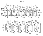
- FIG. FIG. 2 is an exploded perspective view showing a main part of an embodiment of the separator according to the present invention.
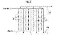
- FIG. 3 is a diagram conceptually showing the relationship between the flow direction of the permeate gas containing the non-permeate gas and the sweep gas and the separation membrane in one embodiment of the separator according to the present invention.
- FIG. 4 conceptually shows another embodiment of the separator according to the present invention.
- FIG. 4A is a sectional view of the separator
- FIG. 4A is a sectional view of the separator
- FIG. 4B is a left side view of the separator
- FIG. 4C is a diagram of the separator. It is a right view.
- FIG. 5 is an exploded perspective view showing a main part of another embodiment of the separator according to the present invention.
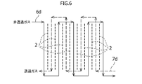
- FIG. 6 is a diagram conceptually showing the relationship between the flow direction of the permeate gas containing the non-permeate gas and the sweep gas and the separation membrane in another embodiment of the separator according to the present invention.
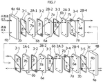
- FIG. 7 is an exploded view showing the main part of another embodiment of the separator according to the present invention. Specifically, FIG. 7 is a perspective view showing an example in which all of the separation membranes have four holes. is there.
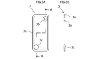
- FIG. 8 shows a sealing member used in another embodiment of the separator according to the present invention, FIG.
- FIG. 8A is a front view thereof, and FIG. 8B is a cross-sectional view taken along line AA in FIG. 8A.
- FIG. 9 is a diagram conceptually showing an example in which separators according to an embodiment of the present invention are arranged in parallel.
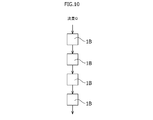
- FIG. 10 is a diagram conceptually showing an example in which separators according to other embodiments of the present invention are arranged in series.
- 11A to 11G are sectional views conceptually showing the sectional shape of the separation membrane applicable to the separator according to the present invention.
- 12A to 12C are diagrams conceptually showing a state in which the unevenness on both surfaces is orthogonal when unevenness is formed on the surface shape of the separation membrane applicable to the separator according to the present invention.
- the separator according to the present invention separates and removes combustible gas such as methane by permeating and removing CO 2 which is a non-combustible gas from natural gas or oil-associated gas, for example, by the separation membrane constituting the separator. It is used for a gas processing plant.
- 1A to 1C and FIG. 2 conceptually show an embodiment of a separator according to the present invention.
- the separator 1A according to the present embodiment includes eight separation membranes 2 that allow CO 2 to permeate from natural gas and oil-associated gas, and seven pieces that are interposed between the separation membranes 2 when the separation membranes 2 are overlapped.
- Sealing member 3 a pair of pressure-resistant plates 4 disposed at both ends of the overlapped separation membrane 2, fastening means 5 for fastening between these pressure-resistant plates, and separation membrane 2 and pressure-resistant plates 4 at both ends. Further, two sealing members 3-1 interposed between them are provided.
- Each of the separation membranes 2 is formed in a substantially rectangular shape and a flat plate shape, and has three holes at three ends of the diagonal four corners at both ends. Further, each of the separation membranes 2 located in the middle excluding both ends has four holes as described later at the diagonal four corners, that is, near the left and right ends of the upper and lower end portions 2a and 2b. Of these four holes, two holes on one diagonal are made non-permeable gas holes 6 for allowing a non-permeable gas to be described later to pass through, and two holes on the other diagonal are passed through the permeated gas. The permeated gas hole 7 is used. All of the separation membranes 2 except for the separation membranes 2-1 at both ends have the same shape and can be shared.
- the separation membrane 2 is, for example, an acid-resistant composite separation membrane obtained by supporting silica gel obtained through hydrolysis of an alkoxysilane containing an ethoxy group or a methoxy group in the pores of the inorganic porous body, or It is preferably formed from a porous substrate such as a ceramic substrate such as alumina, silica, zirconia, and titania. In short, it should be made of an inorganic material and mainly has a function of permeating CO 2. Either is fine. However, when it is desired to separate nonflammable components other than CO 2 , it is a matter of course that the separation membrane 2 formed so as to be able to permeate the nonflammable components is employed.
- the sealing member 3 has an annular outer seal portion 3a along the contour shape of the separation membrane 2, and a pair of annular inner seal portions 3b, 3b at one diagonal.
- the outer seal portion 3a and the inner seal portion 3b of the sealing member 3 are preferably circular in cross section, but the cross sectional shape is not particularly limited.
- Nine sealing members 3 are interposed between each of the eight separation membranes 2 and the pressure-resistant plate 4. In this embodiment, nine sealing members 3 are used, except for the sealing members 3-1 at both ends. They have the same shape and can be shared.
- the sealing member 3 is preferably formed of an elastic resin having low gas permeability (for example, nitrile rubber or butyl rubber), but any material that exhibits a sealing effect may be used. It is not limited.
- the pressure-resistant plate 4 has two holes, which will be described later, lined up and down near one side, and four holes 4c for installing fastening means 5, which will be described later, at four corners thereof (see FIG. 1A).
- the pressure-resistant plates 4 are arranged at both left and right ends, and the left pressure-resistant plate 4 has a non-permeate gas flow hole 4a on the upper side and a permeate gas flow hole 4b on the lower side.
- the pressure plate 4 on the right side has a permeate gas flow hole 4b on the upper side and a non-permeate gas flow hole 4a on the lower side toward the right side.
- the left and right pressure-resistant plates 4 have the same shape and can be shared.
- the fastening means 5 is composed of linear bolts 5a having screw portions formed at both ends, and nuts 5b and 5b fastened to the screw portions at both ends.
- the fastening means 5 inserts the screw portions of the bolts 5a into the holes 4c of the pressure plate 4 on both sides, and fastens the nuts 5b and 5b to these screw portions, so that eight pieces are provided between the pressure plates 4 and 4.
- These separation membranes 2 can be fixed in a superposed manner as will be described later.
- the separation membrane 2 and the sealing member 3 are alternately overlapped, pressure-resistant plates 4 and 4 are disposed at both ends thereof, and can be fixed by tightening the nuts 5b and 5b of the fastening means 5.
- a compression force is applied to the eight separation membranes 2 and the nine sealing members 3 through the pressure-resistant plates 4 and 4 in the overlapping direction. Can do.
- a sealing effect is exhibited between each of the eight separation membranes 2 and between the pressure-resistant plates 4 and 4 as described later.
- the outer sealing portion 3 a of the sealing member 3 is connected to the outside between the adjacent separation membranes 2, 2.
- Separated non-permeate gas chambers 8 and permeate gas chambers 9 are alternately formed in the overlapping direction of the separation membrane 2.
- the sealing members 3 are arranged so that their directions are alternately reversed left and right in the overlapping direction. That is, the positions of the diagonal inner seal portions 3b, 3b of the sealing member 3 are arranged so as to be alternately switched in the overlapping direction.
- the non-permeate gas chamber 8 is a space into which non-permeate gas flows in and out
- the permeate gas chamber 9 is a space into which permeate gas flows in and out.
- the non-permeate gas hole 6 disposed in the upper end 2a of each separation membrane 2 is a non-permeate gas inflow hole 6a through which the non-permeate gas flows into the non-permeate gas chamber 8, and is arranged in the upper end 2a.
- the permeated gas hole 7 provided is a permeated gas inflow hole 7 a for allowing the permeated gas to flow into the permeated gas chamber 9.
- non-permeate gas hole 6 disposed in the lower end 2b of each separation membrane 2 is a non-permeate gas outflow hole 6b through which the non-permeate gas flows out from the non-permeate gas chamber 8, and is arranged in the lower end 2b.
- the permeate gas hole 7 provided is a permeate gas outflow hole 7 b through which the permeate gas flows into the permeate gas chamber 9.
- each of the non-permeate gas chambers 8 has a communication passage 7c between the permeate gas inflow holes 7a and 7a and between the permeate gas outflow holes 7b and 7b of the separation membranes 2 and 2 on both sides thereof. 7c is isolated by the inner seal portions 3b, 3b of the sealing member 3.
- Each of the permeate gas chambers 9 is a sealing member with respect to the communication passages 6c and 6c between the non-permeate gas inflow holes 6a and 6a and the non-permeate gas outflow holes 6b and 6b of the separation membranes 2 and 2 on both sides thereof. 3 are separated by inner seal portions 3b, 3b.
- the non-permeate gas flow path 6d is formed by all the non-permeate gas inflow holes 6a, the non-permeate gas chambers 8 and the non-permeate gas outflow holes 6b, and all the permeate gas inflow holes 7a, the permeate gas chambers 9 and A permeate gas flow path 7d is formed by the permeate gas outflow hole 7b.
- a sweep gas is allowed to flow through the permeate gas flow path 7d as necessary, and the permeate gas is sent out by the sweep gas.
- the non-permeate gas inflow holes 6a in all the non-permeate gas chambers 8 are located at the upper end 2a on the same side of the separation membrane 2, and all non-permeate gas outflows are performed.
- the hole 6b is located at the lower end 2b on the same side of the separation membrane 2.
- the permeate gas inflow holes 7a in all the permeate gas chambers 9 are located at the lower end 2b on the same side of the separation membrane 2, and all the permeate gas outflow holes 7b are located at the upper end 2a on the same side of the separation membrane 2. ing.
- the flow direction of the non-permeate gas in all the non-permeate gas chambers 8 becomes the same direction (so-called co-current flow), and flows toward the lower end 2b side of the separation membrane 2, that is, downward in FIG. 1A.
- the flow direction of the permeate gas in all the permeate gas chambers 9 is the same direction (so-called parallel flow), and flows toward the upper end 2a of the separation membrane 2, that is, upward in FIG. 1A.
- the non-permeate gas inflow hole 6a is located at the lower end 2b of the separation membrane 2
- the non-permeate gas outflow hole 6b is located at the upper end 2a
- the permeate gas inflow hole 7a is located at the upper end 2a of the separation membrane 2.
- the permeate gas outflow hole 7b may be positioned at the lower end 2b on the same side of the separation membrane 2.
- the flow direction of the non-permeate gas in all the non-permeate gas chambers 8 is a direction opposite to the flow direction of the permeate gas in all the permeate gas chambers 9 (so-called countercurrent). . Since the flows in the adjacent non-permeating gas chamber 8 and the permeating gas chamber 9 are completely counterflow, it is possible to prevent a decrease in the transmittance due to the concentration of the permeating gas. Furthermore, a constant flow rate can be designed even when a plurality of separation membranes are stacked and scaled up. Moreover, the shapes of the separation membrane 2 and the seal ring member 3 are the same except for both ends, and can be made common, and the number of types of parts can be minimized.
- FIG. 4A to 4C FIGS. 5 and 6.
- FIG. 5 The elements constituting the separator 1B of the present embodiment have the same functions as those of the elements constituting the separator 1A of the above embodiment. Therefore, elements having the same functions are denoted by the same reference numerals, and detailed descriptions thereof are given. Omitted.
- the separator 1B according to the present embodiment is installed in the same manner as the separator 1A according to the above-described embodiment, with eight separation membranes 2 interposed between the separation membranes 2 when the separation membranes 2 are overlapped.
- a separation membrane 2 ⁇ / b> A formed in a substantially rectangular and flat shape and having two holes formed in the upper end portion 2 a, and a separation membrane formed in the upper and lower end portions 2 a and 2 b closer to one side. 2B is used.
- one of the two holes is a non-permeable gas hole 6 for allowing the non-permeable gas to pass therethrough, and the other hole is allowed to pass the permeable gas.
- the permeate gas hole 7 is used.
- Each of the separation membranes 2A and 2B has the same shape and can be shared.
- the separation membranes 2A and 2B are formed of the same material as the separation membrane 2 of the separator 1A according to the above-described embodiment.
- the sealing member 3 has an annular outer seal portion 3a along the contour shape of the separation membranes 2A and 2B, and one inner seal portion 3b at one corner.
- the outer seal portion 3a and the inner seal portion 3b of the sealing member 3 are preferably circular in cross section, but the cross sectional shape is not particularly limited.
- Each of these sealing members 3 is interposed between each of the eight separation membranes 2 and between the pressure-resistant plates 4 and is used in this embodiment, but all of them have the same shape. , It can be shared.
- the sealing member 3 is made of the same material as the sealing member 3 of the separator 1A according to the above-described embodiment.
- the pressure plate 4 there are a pressure plate 4 ⁇ / b> A in which two holes to be described later are formed side by side near one side and a pressure plate 4 ⁇ / b> B in which two holes to be described later are formed horizontally in FIG. Adopted.
- Each of the pressure plates 4A and 4B has four holes 4c for the fastening means 5 to be installed at the four corners thereof as in the case of the pressure plate 4 according to the above-described embodiment (see FIG. 4A).
- the pressure plate 4A is disposed at the left end in FIG. 4A, and the pressure plate 4B is disposed at the right end in FIG. 4A.
- the two holes of the pressure-resistant plate 4A are formed on the right side, and the upper hole is a non-permeate gas flow hole 4a and the lower hole is a permeate gas flow hole 4b.
- the two holes of the pressure-resistant plate 4B are formed on the lower side of the pressure plate 4B, and the right-hand hole is a permeate gas flow hole 4b and the left-hand hole is a non-permeate gas flow hole 4a.
- the fastening means 5 has exactly the same configuration, operation, and function as that of the separator 1A according to the above-described embodiment, a detailed description thereof will be omitted.
- the separation membrane 2 and the sealing member 3 to be overlaid are denoted by 2A-1, 2B-2, 2A-3, 2B-4, 3B from the left side in FIG. -1, 3-2, 3-3, 3-4, and 3-5 will be described.
- the first separation membrane 2A-1 from the left is upright
- the second separation membrane 2B-2 is upright
- the third separation membrane 2A-3 is upside down
- the fourth separation membrane 2B-4 is reversed left and right, and thereafter repeatedly arranged in this order and overlaid as described later.
- the sealing member 3 also corresponds to the separation membranes 2A-1, 2B-2, 2A-3, 2B-4, and as shown in FIG. 5, the first sealing member 3-1 from the left is upright.
- the second sealing member 3-2 is horizontally reversed
- the third sealing member 3-3 is horizontally reversed
- the fourth sealing member 3-4 is vertically reversed.
- a sealing member 3-5 (same as 3-1) is interposed between the last separation membrane 2B-4 and the right pressure plate 4B.
- all the separation membranes 2 and the sealing members 3 are fixed in a compressed state in the same manner as in the above-described one embodiment, using the fastening means 5 in a state where they are arranged as described above.
- a non-permeate gas chamber 8 partially defined in the separation membrane 2A-1 is formed in the space between the pressure-resistant plate 4A on the left side and the separation membrane 2A-1, and next to it.
- a permeate gas chamber 9 is formed in the space between the separation membrane 2A-1 and the separation membrane 2B-2, and a non-permeate gas chamber 8 is formed in the space between the separation membrane 2B-2 and the separation membrane 2A-3 next to it.
- a permeating gas chamber 9 is formed in the space between the separation membrane 2A-3 and the separation membrane 2B-4 next to it, and thereafter repeatedly formed in this order, and then repeatedly arranged in this order, and the last separation membrane 2B-
- a non-permeating gas chamber 8 is formed in a space between 4 and the right pressure plate 4B.
- the above configuration allows the non-permeating gas hole 6 of the separation membrane 2A-1 to pass through the non-permeating gas from the non-permeating gas chamber 8 between the pressure-resistant plate 4A and the separation membrane 2A-1.
- a non-permeating gas outflow hole 6b is formed in the lower end 2b of the separation membrane 2A-1, and the permeating gas hole 7 of the separation membrane 2A-1 is formed between the separation membrane 2A-1 and the separation membrane 2B-2.
- a permeate gas outflow hole 7b through which the permeate gas flows out from the permeate gas chamber 9 is formed in the lower end 2b of the separation membrane 2A-1.
- the non-permeate gas chamber 8 between the pressure plate 4A and the separation membrane 2A-1 is a communication passage 7c between the permeate gas flow hole 4b of the pressure plate 4A and the permeate gas outflow hole 7b of the separation membrane 2A-1. (See FIGS. 4A and 5), they are isolated by the inner seal portion 3b of the sealing member 3-1.
- the non-permeating gas hole 6 between the separation membrane 2B-2 and the separation membrane 2A-3 is formed by matching the non-permeating gas hole 6 of the separation membrane 2B-2 with the non-permeating outflow hole 6b of the separation membrane 2A-1.
- 8 is formed in the lower end portion 2b of the separation membrane 2B-2 as a non-permeate gas inflow hole 6a for allowing the non-permeate gas to flow in, and the permeation gas hole 7 of the separation membrane 2B-2 is formed between the separation membrane 2A-1 and the separation membrane.
- a permeate gas inflow hole 7a for allowing permeate gas to flow into the permeate gas chamber 9 between 2B-2 is formed at the upper end 2a of the separation membrane 2B-2.
- the permeate gas chamber 9 between the separation membrane 2A-1 and the separation membrane 2B-2 is formed between the non-permeate gas outflow hole 6b of the separation membrane 2A-1 and the non-permeate gas inflow hole 6a of the separation membrane 2B-2.
- the communication path 6c between them (see FIGS. 4A and 5) is isolated by the inner seal portion 3b of the sealing member 3-2.
- non-permeate gas hole 6 of the separation membrane 2A-3 is used as a non-permeate gas outflow hole 6b through which the non-permeate gas flows out from the non-permeate gas chamber 8 between the separation membrane 2B-2 and the separation membrane 2A-3.
- the separation membrane 2A-3 and the separation membrane are formed at the upper end 2a of the separation membrane 2A-3, and the permeation gas holes 7 of the separation membrane 2A-3 are aligned with the permeation gas inflow holes 7a of the separation membrane 2B-2.
- a permeate gas outflow hole 7b for allowing permeate gas to flow out of the permeate gas chamber 9 between 2B-4 is formed at the upper end 2a of the separation membrane 2A-3.
- the non-permeate gas chamber 8 between the separation membrane 2B-2 and the separation membrane 2A-3 is between the permeate gas inflow hole 7a of the separation membrane 2B-2 and the permeate gas outflow hole 7b of the separation membrane 2A-3.
- the communication passage 7c (see FIGS. 4A and 5) is isolated by the inner seal portion 3b of the sealing member 3-3.
- non-permeating gas hole 6 of the separation membrane 2B-4 is matched with the non-permeating gas outflow hole 6b of the separation membrane 2A-3, so that the separation membrane 2A-1 is separated from the next separation membrane 2B-4.
- a non-permeate gas inflow hole 6a for allowing non-permeate gas to flow into the non-permeate gas chamber 8 is formed at the upper end 2a of the separation membrane 2B-4, and the permeate gas hole 7 of the separation membrane 2B-4 is formed as a separation membrane 2A-.
- the permeate gas chamber 9 between the separation membrane 2A-3 and the separation membrane 2B-4 is formed between the non-permeate gas outflow hole 6b of the separation membrane 2A-3 and the non-permeate gas inflow hole 6a of the separation membrane 2B-4.
- the communication path 6c (see FIG. 4A) is isolated by the inner seal portion 3b of the sealing member 3-4 (see FIGS. 4A and 5).
- the subsequent separation membrane 2A-1 to the next separation membrane 2B-4 and the right pressure plate 4B are configured in the same order as described above, description thereof will be omitted.
- all the non-permeate gas inflow holes 6a, the non-permeate gas chambers 8 and the non-permeate gas outflow holes 6b form a non-permeate gas flow path 6d, and all the permeate gas inflow holes 7a and the permeate gas chambers 9 are formed.
- a permeate gas flow path 7d is formed by the permeate gas outflow hole 7b (see FIG. 6).
- a sweep gas is allowed to flow through the permeate gas channel 7d as necessary, and the permeate gas is sent out by the sweep gas.
- the non-permeate gas passes through the non-permeate gas flow hole 4a of the left pressure plate 4A in FIG. It is introduced and flows through the above-described non-permeate gas passage 6d so as to come out from the non-permeate gas flow hole 4a of the right pressure-resistant plate 4B.
- CO 2 which is a non-combustible gas component contained in the natural gas / oil-associated gas, passes through the separation membranes 2 on both sides when passing through each non-permeate gas chamber 8, and the adjacent permeate gas chambers. It moves to 9, 9 and becomes permeate gas, and is separated through permeate gas channel 7d.
- the sweep gas when the sweep gas is used, the sweep gas is introduced through the permeate gas flow hole 4b of the right pressure plate 4B, flows through the permeate gas flow path 7d, and flows through the left pressure plate 4A.
- the permeate gas circulation holes 4b can be extracted outside.
- the sweep gas By using the sweep gas, the permeate gas that has permeated through the separation membranes 2 on both sides when passing through each permeate gas chamber 9 can be efficiently captured and sent to the outside. Furthermore, even when the number of separation membranes becomes plural according to the processing capacity and the like, both the permeation side and the non-permeation side are one-through, and there is no need to consider flow distribution.
- the separators 1A of the above-described embodiment are configured in parallel, since the flow velocity is high, concentration polarization can be avoided and high permeation performance can be obtained.
- FIGS. 7A and 8B illustrate the case where the separator 1B shown in FIGS. 4A to 4C and FIG. 5 employs the separation membrane 2 having four holes.
- a disc-shaped seal portion 3 c (see FIGS. 8A and 8B) is provided in the sealing member 3 to seal unnecessary holes for unnecessary holes.
- the disk-shaped seal portion 3c is provided at a diagonal opposite to the inner seal portion 3b.
- FIG. 9 shows a configuration in which a plurality of separators 1A according to the first embodiment are connected in parallel.
- the separator 1A is configured such that the non-permeate gas flow path 6d and the permeate gas flow path 7d branch in the middle and flow in parallel, so that it is necessary depending on the required separation performance. If a large number are connected in parallel, a high-performance separator can be easily configured even in the case of the small separator 1A.
- FIG. 10 shows a configuration in which a plurality of separators 1B according to the other embodiments are connected in series.
- the separator 1B is configured so that the non-permeating gas flow path 6d and the permeating gas flow path 7d flow in a DC manner without branching on the way, so that according to the required separation performance. If the required number is connected in series, a high-performance separator can be easily configured even in the case of the small separator 1B. Of course, it may be configured by combining the separator 1A connected in parallel and the separator 1B connected in series as described above, and can meet the demand for higher separation performance. Is possible.
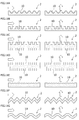
- FIGS. 11A to 11G and FIG. 12 show other examples of the separation membrane 2 that can be used in any separator as well as the above-described embodiments.
- 11A to 11E show the separation membrane 2 having a striped groove (or unevenness) 10 formed on the surface thereof
- FIGS. 11F and 11G show the separation membrane 2 itself having a corrugated cross section.
- . 11A shows a stepped groove 10 having a mountain-shaped section
- FIG. 11B shows a groove 10 having a rectangular cross section
- FIG. 11C shows the groove 10 shown in FIG. 11B on both sides of the separation membrane.
- FIG. 11D shows a structure in which the groove 10 shown in FIG. 11B is formed on both surfaces of the separation membrane 2 by shifting by the width of the groove
- FIG. 11E shows a groove 10 having one surface with a ripple shape in cross section.
- FIG. 11F shows the separation membrane 2 having a corrugated shape with a square cross section
- FIG. 11G shows the separation membrane 2 having a
- the diagrams shown on the left side show how the non-permeate gas or the permeate gas flows in a direction perpendicular to the groove 10
- the diagrams on the right side show the groove 10 It shows a state in which a non-permeate gas or a permeate gas flows in a direction in which the groove is formed, that is, in a direction perpendicular to the case shown in the left side.
- the direction in which the non-permeate gas or the permeate gas flows may be any direction, and in the adjacent non-permeate gas channel and the permeate gas channel, the directions of the grooves 10 are perpendicular to each other. However, it is not particularly limited.
- the surface area of the separation membrane 2 can be increased, and turbulent flow in the surface flow can be promoted, so that the permeation performance can be greatly improved. Further, in the separation membrane 2 as shown in FIGS. 11F and 11G, the thickness of the separation membrane 2 can be made uniform in the width direction, and the production of the separation membrane is facilitated.
- the location where the non-permeating gas hole and the permeating gas hole are formed is the upper end 2a or the lower end 2b of the separation membrane 2.
- the present invention is not limited to this, and the upper and lower ends of the separation membrane. Other one end or the other end may not be used.
- the upper end portion (or one end portion) and the lower end portion (the other end portion) strictly mean the upper end portion (or one end portion) and the lower end portion (or the other end portion) of the separation membrane. In short, it may be an appropriate place that is appropriately separated from each other, and depending on the shape of the separation membrane, it may not necessarily be the upper end (or one end) and the lower end (or the other end) of the separation membrane.
- the number of holes formed in the separation membrane is not particularly limited, but preferably the number of holes may be an even number. Providing an even number of holes is advantageous in that the separation membrane can be shared. In this case, when an odd number of holes is sufficient as in the separation membranes at both ends, as described above, unnecessary holes out of the even number of holes may be sealed by providing a disk-shaped seal portion on the sealing member. Of course, a separation membrane provided with an odd number of holes may be formed separately. Furthermore, in both of the above embodiments, the hole formed in the separation membrane and the inner seal portion and the disc-shaped seal portion of the sealing member are formed at the diagonal corners, but the formation location is not particularly limited and is required. May be appropriately formed in accordance with the position of the hole of the separation membrane.
- the shape of the separation membrane is rectangular.
- the present invention is not limited to this, and may be, for example, a circle, other polygons, a long shape, etc.
- the shape is not particularly limited.
- the shapes of the sealing member and the pressure plate may be determined as appropriate in accordance with the shape of the separation membrane.
- eight separation membranes are employed.
- the present invention is not limited to this, and it is a matter of course that the number of separation membranes may be increased.
- the number of separation membranes is preferably a multiple of 4. While the embodiments of the present invention have been described above, the present invention is not limited to the above-described embodiments, and various modifications and changes can be made based on the technical idea of the present invention.
Landscapes
- Chemical & Material Sciences (AREA)
- Chemical Kinetics & Catalysis (AREA)
- Oil, Petroleum & Natural Gas (AREA)
- Engineering & Computer Science (AREA)
- General Chemical & Material Sciences (AREA)
- Analytical Chemistry (AREA)
- Organic Chemistry (AREA)
- Separation Using Semi-Permeable Membranes (AREA)
Applications Claiming Priority (2)
| Application Number | Priority Date | Filing Date | Title |
|---|---|---|---|
| JP2015038688A JP2016159212A (ja) | 2015-02-27 | 2015-02-27 | 分離器 |
| JP2015-038688 | 2015-02-27 |
Publications (1)
| Publication Number | Publication Date |
|---|---|
| WO2016136048A1 true WO2016136048A1 (ja) | 2016-09-01 |
Family
ID=56788174
Family Applications (1)
| Application Number | Title | Priority Date | Filing Date |
|---|---|---|---|
| PCT/JP2015/082378 Ceased WO2016136048A1 (ja) | 2015-02-27 | 2015-11-18 | 分離器 |
Country Status (2)
| Country | Link |
|---|---|
| JP (1) | JP2016159212A (enExample) |
| WO (1) | WO2016136048A1 (enExample) |
Cited By (1)
| Publication number | Priority date | Publication date | Assignee | Title |
|---|---|---|---|---|
| WO2021045156A1 (ja) * | 2019-09-03 | 2021-03-11 | 国立大学法人九州大学 | 多孔質膜及びその製造方法、分離膜、積層モジュール、並びに、気体分離モジュール |
Families Citing this family (1)
| Publication number | Priority date | Publication date | Assignee | Title |
|---|---|---|---|---|
| KR101910296B1 (ko) | 2017-11-17 | 2018-10-22 | 한국에너지기술연구원 | 금속프레임을 이용한 세라믹 산소분리막 모듈, 및 산소분리막 장치 |
Citations (6)
| Publication number | Priority date | Publication date | Assignee | Title |
|---|---|---|---|---|
| JPS5417380A (en) * | 1977-06-15 | 1979-02-08 | Gen Electric | Selective component removal method and package membrane |
| JPS55137007A (en) * | 1979-04-14 | 1980-10-25 | Horiba Ltd | Semipermeable membrane dehumidifier |
| JPH08103637A (ja) * | 1994-09-14 | 1996-04-23 | Sartorius Gmbh | 吸着膜で物質を分離する濾過ユニット |
| JPH11309310A (ja) * | 1998-02-24 | 1999-11-09 | Chisso Corp | 筒状成形体及びそれを用いたフィルタ―エレメント |
| JP2012066239A (ja) * | 2010-08-24 | 2012-04-05 | Toray Ind Inc | 分離膜および分離膜エレメント |
| JP2014036953A (ja) * | 2012-08-10 | 2014-02-27 | Pall Corp | 流体処理アセンブリ、流体処理セグメント、および、流体処理システムの製造方法。 |
Family Cites Families (3)
| Publication number | Priority date | Publication date | Assignee | Title |
|---|---|---|---|---|
| JPS63319002A (ja) * | 1987-06-19 | 1988-12-27 | Matsushita Electric Ind Co Ltd | 分離膜モジュ−ル |
| JP4806867B2 (ja) * | 2001-07-23 | 2011-11-02 | トヨタ自動車株式会社 | 水素抽出装置 |
| JP4910261B2 (ja) * | 2001-09-07 | 2012-04-04 | トヨタ自動車株式会社 | 積層構造の水素分離装置 |
-
2015
- 2015-02-27 JP JP2015038688A patent/JP2016159212A/ja active Pending
- 2015-11-18 WO PCT/JP2015/082378 patent/WO2016136048A1/ja not_active Ceased
Patent Citations (6)
| Publication number | Priority date | Publication date | Assignee | Title |
|---|---|---|---|---|
| JPS5417380A (en) * | 1977-06-15 | 1979-02-08 | Gen Electric | Selective component removal method and package membrane |
| JPS55137007A (en) * | 1979-04-14 | 1980-10-25 | Horiba Ltd | Semipermeable membrane dehumidifier |
| JPH08103637A (ja) * | 1994-09-14 | 1996-04-23 | Sartorius Gmbh | 吸着膜で物質を分離する濾過ユニット |
| JPH11309310A (ja) * | 1998-02-24 | 1999-11-09 | Chisso Corp | 筒状成形体及びそれを用いたフィルタ―エレメント |
| JP2012066239A (ja) * | 2010-08-24 | 2012-04-05 | Toray Ind Inc | 分離膜および分離膜エレメント |
| JP2014036953A (ja) * | 2012-08-10 | 2014-02-27 | Pall Corp | 流体処理アセンブリ、流体処理セグメント、および、流体処理システムの製造方法。 |
Cited By (1)
| Publication number | Priority date | Publication date | Assignee | Title |
|---|---|---|---|---|
| WO2021045156A1 (ja) * | 2019-09-03 | 2021-03-11 | 国立大学法人九州大学 | 多孔質膜及びその製造方法、分離膜、積層モジュール、並びに、気体分離モジュール |
Also Published As
| Publication number | Publication date |
|---|---|
| JP2016159212A (ja) | 2016-09-05 |
Similar Documents
| Publication | Publication Date | Title |
|---|---|---|
| US20210075035A1 (en) | Humidifier, for Example for a Fuel Cell | |
| EP0814896B1 (en) | Filtration cassette article, and filter comprising the same | |
| JPWO2013061474A1 (ja) | 流体分離装置および混合流体の選択分離方法 | |
| CN104941394A (zh) | 气体分离系统及富化气体的制造方法 | |
| WO2003040166A3 (en) | Membrane adsorber device | |
| JP7298101B2 (ja) | 3層構造の供給スペーサおよびそれを含む逆浸透フィルタモジュール | |
| WO2016136048A1 (ja) | 分離器 | |
| CA2842476A1 (en) | Membrane module for organophilic pervaporation | |
| US8152910B2 (en) | Modular gas-separating adsorbers | |
| JP2016538988A (ja) | 空気分離装置、不活性化装置、及び、このような装置を備えた航空機 | |
| US11517856B2 (en) | Flow path spacer and spiral membrane element | |
| US20210205761A1 (en) | Flow path spacer and spiral membrane element | |
| WO2014119742A1 (ja) | セラミックフィルタの使用方法及びフィルタ装置 | |
| JP2007516072A (ja) | 動的膜ウェーハアセンブリおよび方法 | |
| JP2016159212A5 (enExample) | ||
| WO2016157360A1 (ja) | 膜分離装置 | |
| JP6217370B2 (ja) | 分離膜モジュール | |
| CN204395783U (zh) | 一种用于内壁涂覆分离层的管式膜的膜组件 | |
| KR20190031715A (ko) | 4층 구조의 공급 스페이서 | |
| WO2016199726A1 (ja) | 分離膜エレメント及び膜分離装置 | |
| KR101783211B1 (ko) | 막증류 모듈 | |
| Ismail et al. | Membrane modules and process design | |
| CN104906859B (zh) | 一种过滤膜支架 | |
| KR102065704B1 (ko) | 유로수축 개선 스페이서 및 이를 포함하는 수처리용 막 모듈 | |
| CN205760651U (zh) | 一种陶瓷膜片制成的压力式陶瓷膜装置 |
Legal Events
| Date | Code | Title | Description |
|---|---|---|---|
| 121 | Ep: the epo has been informed by wipo that ep was designated in this application |
Ref document number: 15883338 Country of ref document: EP Kind code of ref document: A1 |
|
| NENP | Non-entry into the national phase |
Ref country code: DE |
|
| 122 | Ep: pct application non-entry in european phase |
Ref document number: 15883338 Country of ref document: EP Kind code of ref document: A1 |