WO2016136048A1 - Separator - Google Patents
Separator Download PDFInfo
- Publication number
- WO2016136048A1 WO2016136048A1 PCT/JP2015/082378 JP2015082378W WO2016136048A1 WO 2016136048 A1 WO2016136048 A1 WO 2016136048A1 JP 2015082378 W JP2015082378 W JP 2015082378W WO 2016136048 A1 WO2016136048 A1 WO 2016136048A1
- Authority
- WO
- WIPO (PCT)
- Prior art keywords
- separation membrane
- gas
- permeate gas
- hole
- permeate
- Prior art date
Links
- 239000007789 gas Substances 0.000 claims abstract description 393
- 238000000926 separation method Methods 0.000 claims abstract description 306
- 239000012528 membrane Substances 0.000 claims abstract description 305
- 238000007789 sealing Methods 0.000 claims abstract description 61
- VNWKTOKETHGBQD-UHFFFAOYSA-N methane Chemical compound C VNWKTOKETHGBQD-UHFFFAOYSA-N 0.000 claims abstract description 26
- 239000003345 natural gas Substances 0.000 claims abstract description 10
- 239000012466 permeate Substances 0.000 claims description 255
- 230000015572 biosynthetic process Effects 0.000 claims description 3
- 239000003209 petroleum derivative Substances 0.000 abstract 1
- 238000010586 diagram Methods 0.000 description 8
- VYPSYNLAJGMNEJ-UHFFFAOYSA-N Silicium dioxide Chemical compound O=[Si]=O VYPSYNLAJGMNEJ-UHFFFAOYSA-N 0.000 description 3
- 230000000694 effects Effects 0.000 description 3
- 239000000463 material Substances 0.000 description 3
- 229920000459 Nitrile rubber Polymers 0.000 description 2
- GWEVSGVZZGPLCZ-UHFFFAOYSA-N Titan oxide Chemical compound O=[Ti]=O GWEVSGVZZGPLCZ-UHFFFAOYSA-N 0.000 description 2
- MCMNRKCIXSYSNV-UHFFFAOYSA-N Zirconium dioxide Chemical compound O=[Zr]=O MCMNRKCIXSYSNV-UHFFFAOYSA-N 0.000 description 2
- 230000002349 favourable effect Effects 0.000 description 2
- 238000002955 isolation Methods 0.000 description 2
- 239000000758 substrate Substances 0.000 description 2
- 239000002253 acid Substances 0.000 description 1
- PNEYBMLMFCGWSK-UHFFFAOYSA-N aluminium oxide Inorganic materials [O-2].[O-2].[O-2].[Al+3].[Al+3] PNEYBMLMFCGWSK-UHFFFAOYSA-N 0.000 description 1
- 239000000919 ceramic Substances 0.000 description 1
- 239000002131 composite material Substances 0.000 description 1
- 230000006835 compression Effects 0.000 description 1
- 238000007906 compression Methods 0.000 description 1
- 238000010612 desalination reaction Methods 0.000 description 1
- 125000001301 ethoxy group Chemical group [H]C([H])([H])C([H])([H])O* 0.000 description 1
- 230000007062 hydrolysis Effects 0.000 description 1
- 238000006460 hydrolysis reaction Methods 0.000 description 1
- 229910010272 inorganic material Inorganic materials 0.000 description 1
- 239000011147 inorganic material Substances 0.000 description 1
- 238000004519 manufacturing process Methods 0.000 description 1
- 125000000956 methoxy group Chemical group [H]C([H])([H])O* 0.000 description 1
- 238000012986 modification Methods 0.000 description 1
- 230000004048 modification Effects 0.000 description 1
- 230000035699 permeability Effects 0.000 description 1
- 230000010287 polarization Effects 0.000 description 1
- 239000011148 porous material Substances 0.000 description 1
- 239000011347 resin Substances 0.000 description 1
- 229920005989 resin Polymers 0.000 description 1
- 239000013535 sea water Substances 0.000 description 1
- 239000000741 silica gel Substances 0.000 description 1
- 229910002027 silica gel Inorganic materials 0.000 description 1
- 239000000377 silicon dioxide Substances 0.000 description 1
- 238000002834 transmittance Methods 0.000 description 1
- 238000009423 ventilation Methods 0.000 description 1
Images


Classifications
-
- B—PERFORMING OPERATIONS; TRANSPORTING
- B01—PHYSICAL OR CHEMICAL PROCESSES OR APPARATUS IN GENERAL
- B01D—SEPARATION
- B01D53/00—Separation of gases or vapours; Recovering vapours of volatile solvents from gases; Chemical or biological purification of waste gases, e.g. engine exhaust gases, smoke, fumes, flue gases, aerosols
- B01D53/22—Separation of gases or vapours; Recovering vapours of volatile solvents from gases; Chemical or biological purification of waste gases, e.g. engine exhaust gases, smoke, fumes, flue gases, aerosols by diffusion
-
- B—PERFORMING OPERATIONS; TRANSPORTING
- B01—PHYSICAL OR CHEMICAL PROCESSES OR APPARATUS IN GENERAL
- B01D—SEPARATION
- B01D63/00—Apparatus in general for separation processes using semi-permeable membranes
-
- B—PERFORMING OPERATIONS; TRANSPORTING
- B01—PHYSICAL OR CHEMICAL PROCESSES OR APPARATUS IN GENERAL
- B01D—SEPARATION
- B01D63/00—Apparatus in general for separation processes using semi-permeable membranes
- B01D63/08—Flat membrane modules
-
- B—PERFORMING OPERATIONS; TRANSPORTING
- B01—PHYSICAL OR CHEMICAL PROCESSES OR APPARATUS IN GENERAL
- B01D—SEPARATION
- B01D69/00—Semi-permeable membranes for separation processes or apparatus characterised by their form, structure or properties; Manufacturing processes specially adapted therefor
-
- C—CHEMISTRY; METALLURGY
- C10—PETROLEUM, GAS OR COKE INDUSTRIES; TECHNICAL GASES CONTAINING CARBON MONOXIDE; FUELS; LUBRICANTS; PEAT
- C10L—FUELS NOT OTHERWISE PROVIDED FOR; NATURAL GAS; SYNTHETIC NATURAL GAS OBTAINED BY PROCESSES NOT COVERED BY SUBCLASSES C10G, C10K; LIQUEFIED PETROLEUM GAS; ADDING MATERIALS TO FUELS OR FIRES TO REDUCE SMOKE OR UNDESIRABLE DEPOSITS OR TO FACILITATE SOOT REMOVAL; FIRELIGHTERS
- C10L3/00—Gaseous fuels; Natural gas; Synthetic natural gas obtained by processes not covered by subclass C10G, C10K; Liquefied petroleum gas
- C10L3/06—Natural gas; Synthetic natural gas obtained by processes not covered by C10G, C10K3/02 or C10K3/04
- C10L3/10—Working-up natural gas or synthetic natural gas
-
- Y—GENERAL TAGGING OF NEW TECHNOLOGICAL DEVELOPMENTS; GENERAL TAGGING OF CROSS-SECTIONAL TECHNOLOGIES SPANNING OVER SEVERAL SECTIONS OF THE IPC; TECHNICAL SUBJECTS COVERED BY FORMER USPC CROSS-REFERENCE ART COLLECTIONS [XRACs] AND DIGESTS
- Y02—TECHNOLOGIES OR APPLICATIONS FOR MITIGATION OR ADAPTATION AGAINST CLIMATE CHANGE
- Y02C—CAPTURE, STORAGE, SEQUESTRATION OR DISPOSAL OF GREENHOUSE GASES [GHG]
- Y02C20/00—Capture or disposal of greenhouse gases
- Y02C20/40—Capture or disposal of greenhouse gases of CO2
Landscapes
- Chemical & Material Sciences (AREA)
- Chemical Kinetics & Catalysis (AREA)
- Oil, Petroleum & Natural Gas (AREA)
- Engineering & Computer Science (AREA)
- General Chemical & Material Sciences (AREA)
- Analytical Chemistry (AREA)
- Organic Chemistry (AREA)
- Separation Using Semi-Permeable Membranes (AREA)
Abstract
Provided is a separator that can be easily increased in size according to required separation performance, that can be assembled easily, and for which, when any separation membrane fails, only that failed separation membrane needs to be replaced. The separator is configured such that: a plurality of plate shaped separation membranes 2 for separating permeable gases by allowing CO2 and the like, which are noncombustible gas components included in natural gas/associated petroleum gas, to pass through and a plurality of sealing members 3 are stacked alternately, and non-permeable gas chambers 8 and permeable gas chambers 9 are formed alternately between the adjacent separation membranes; and a non-permeable gas flow path is formed by non-permeable gas holes 6, which are formed in the separation membranes 2, and the non-permeable gas chambers 8, and a permeable gas flow path is formed by permeable gas holes 7, which are formed in the separation membranes 2, and the permeable gas chambers 9.
Description
本発明は、分離器に関し、詳しくは、例えば天然ガスや油随伴ガスからCO2等の非可燃性ガスを除去し、メタン等の可燃性ガスを分離するガス処理プラントで用いられる分離器に関する。
The present invention relates to a separator, and more particularly to a separator used in a gas processing plant that removes non-combustible gas such as CO 2 from natural gas or oil-associated gas and separates combustible gas such as methane.
従来より、天然ガス・油随伴ガスからCO2等の非可燃性ガスを分離する、いわゆる天然ガス・油随伴ガス処理向けの分離器がある。このような分離器で用いられる分離手段としては、有機膜と無機膜を用いたものがあり、この2種に大別される。
ここで、有機膜を用いた分離器としては,海水淡水化で用いられるRO膜同様,中空糸状あるいはスパイラル状の分離膜を円筒の容器に格納した構成となっているものが一般的である。また、無機膜を用いた分離器としては、チューブラー状のもの、モノリス型(集積構造)のもの等があり,これらも円筒の耐圧容器に格納された構成となっているものが一般的である。 2. Description of the Related Art Conventionally, there is a separator for so-called natural gas / oil-associated gas processing that separates non-combustible gas such as CO 2 from natural gas / oil-associated gas. Separation means used in such a separator includes those using an organic membrane and an inorganic membrane, and is roughly classified into these two types.
Here, as a separator using an organic membrane, a separator having a hollow fiber-like or spiral-like separation membrane stored in a cylindrical container is generally similar to the RO membrane used in seawater desalination. In addition, separators using inorganic membranes include a tubular type and a monolith type (integrated structure), and these are also generally stored in a cylindrical pressure vessel. is there.
ところで、上記したような分離器では、無機膜が有機膜に比べ分離性能が高いことから、無機膜の方が適していると考えられるが、分離器の構造や該無機膜のハンドリングの難しさから、次のような課題があった。
すなわち、無機膜をチューブラー状に構成した分離膜の場合は、1本ずつシールする必要があり,シール点数が莫大となる欠点があった。また、無機膜を集積させた集積型モノリス型の分離膜の場合は、一部が欠けると、膨大な分離面を持つ1本分の分離膜が無駄になるという不具合があった。 By the way, in the separator as described above, since the inorganic membrane has higher separation performance than the organic membrane, the inorganic membrane is considered to be more suitable. However, the structure of the separator and the difficulty of handling the inorganic membrane are considered. Therefore, there were the following problems.
That is, in the case of a separation membrane in which the inorganic membrane is formed in a tubular shape, it is necessary to seal one by one, and there is a disadvantage that the number of sealing points becomes enormous. In addition, in the case of an integrated monolith type separation membrane in which inorganic membranes are integrated, there is a problem that if one part is missing, one separation membrane having a huge separation surface is wasted.
この特許文献1に記載の分離器は、気体を透過させる分離膜を備え、これらの分離膜間に通気室を備えた気体分離膜を複数所定間隔にて重ね合わせた構成となっており、分離膜を透過してきた気体を、側方に形成した通路にて取り出すようにしたものである。
The separator described in Patent Document 1 includes a separation membrane that allows gas to permeate, and has a configuration in which a plurality of gas separation membranes including a ventilation chamber are overlapped at a predetermined interval between the separation membranes. The gas that has permeated the membrane is taken out through a passage formed on the side.
しかしながら、この特許文献1に記載の分離器においては、透過ガスの集積は可能であるが、分離膜を透過しない非透過ガスであるメタン等の可燃性ガスは雰囲気中に拡散するため集積ができないという問題がある。
However, in the separator described in Patent Document 1, permeate gas can be accumulated, but combustible gas such as methane, which is a non-permeate gas that does not permeate the separation membrane, diffuses into the atmosphere and cannot be accumulated. There is a problem.
本発明は上記実状に鑑みてなされたものであって、その目的は、要求される分離性能に応じて大型化が容易であり、その組立性も良好であり、いずれかの分離膜が破損した場合でも、その破損した一部の分離膜の交換だけで済む分離器を提供することにある。
The present invention has been made in view of the above circumstances, and its purpose is that it can be easily enlarged in accordance with the required separation performance, its assemblability is good, and one of the separation membranes is damaged. Even in such a case, it is an object of the present invention to provide a separator in which only a part of the damaged separation membrane is replaced.
本発明に係る分離器では、上記目的を達成するために、天然ガス・油随伴ガスに含まれる非可燃性ガス成分であるCO2等を透過させて透過ガスを分離する複数の平板状の分離膜と、複数のシーリング部材とを備え、上記分離膜は、非透過ガスを通過させるための1または複数の非透過ガス孔と、上記透過ガスを通過させるための1または複数の透過ガス孔とを有し、上記分離膜と上記シーリング部材を交互に重ね合わせて、それぞれ隣合う分離膜間に外部に対して隔絶された、非透過ガスが流入・流出する非透過ガス室と、透過ガスが流入・流出する透過ガス室を、上記分離膜の重ね合わせ方向に交互に形成し、上記非透過ガス室のそれぞれは、その両側の分離膜の上記透過ガス孔間の連絡通路に対して、上記シーリング部材により隔絶され、上記透過ガス室のそれぞれは、その両側の分離膜の上記非透過ガス孔間の連絡通路に対して、上記シーリング部材により隔絶され、もって、上記非透過ガス孔および上記非透過ガス室によって非透過ガス流路を形成するとともに、上記透過ガス孔および上記透過ガス室によって透過ガス流路を形成する構成としている。
In the separator according to the present invention, in order to achieve the above object, a plurality of plate-like separations that separate the permeated gas by permeating CO 2 or the like, which is a non-combustible gas component contained in natural gas / oil-associated gas. The separation membrane includes one or more non-permeating gas holes for allowing a non-permeating gas to pass therethrough, and one or more permeating gas holes for allowing the permeating gas to pass therethrough. The separation membrane and the sealing member are alternately stacked, and the non-permeate gas chamber into which the non-permeate gas flows in and out is isolated between the adjacent separation membranes, and the permeate gas is Inflow and outflow permeate gas chambers are alternately formed in the overlapping direction of the separation membrane, and each of the non-permeate gas chambers is connected to the communication passage between the permeate gas holes of the separation membrane on both sides thereof. Isolated by sealing member Each of the permeate gas chambers is isolated by the sealing member with respect to the communication passage between the non-permeate gas holes of the separation membrane on both sides thereof, and thus, by the non-permeate gas holes and the non-permeate gas chambers. A non-permeate gas channel is formed, and a permeate gas channel is formed by the permeate gas hole and the permeate gas chamber.
本発明では、上記分離器において、上記分離膜のそれぞれは一対の非透過ガス孔と一対の透過ガス孔を有し、該一対の非透過ガス孔のうち、一方の非透過ガス孔を、上記非透過ガス室に非透過ガスを流入させる非透過ガス流入孔として上記分離膜の一端部に配設するとともに、他方の非透過ガス孔を、上記非透過ガス室から非透過ガスを流出させる非透過ガス流出孔として上記分離膜の他端部に配設し、他方、該一対の透過ガス孔のうち、その一方の透過ガス孔を、上記透過ガス室に透過ガスを流入させる透過ガス流入孔として上記分離膜の他端部に配設するとともに、その他方の透過ガス孔を、上記透過ガス室から透過ガスを流出させる透過ガス流出孔として上記分離膜の一端部に配設した構成とすることが可能である。
In the present invention, in the separator, each of the separation membranes has a pair of non-permeating gas holes and a pair of permeating gas holes. A non-permeable gas inflow hole through which the non-permeate gas flows into the non-permeate gas chamber is disposed at one end of the separation membrane, and the other non-permeate gas hole is configured to pass the non-permeate gas out of the non-permeate gas chamber. A permeate gas outflow hole is provided at the other end of the separation membrane, and one of the pair of permeate gas holes is a permeate gas inflow hole through which the permeate gas flows into the permeate gas chamber. The other permeate gas hole is disposed at one end of the separation membrane as a permeate gas outflow hole for allowing the permeate gas to flow out of the permeate gas chamber. It is possible.
本発明では、上記分離器において、重ね合わされた上記分離膜のうち、隣合う第一の分離膜と第二の分離膜の間の空間が上記透過ガス室であるとき、該第一の分離膜の上記非透過ガス孔を、該第一の分離膜によって一部画成された上記非透過ガス室から非透過ガスを流出させる非透過ガス流出孔として該第一の分離膜の他端部に形成するとともに、該第一の分離膜の上記透過ガス孔を、該第一の分離膜と上記第二の分離膜との間の上記透過ガス室から透過ガス孔を流出させる透過ガス流出孔として、該第一の分離膜の他端部に形成し、上記第二の分離膜の上記非透過ガス孔を、上記第一の分離膜の上記非透過流出孔に合致させて、該第二の分離膜と上記第三の分離膜との間の上記非透過ガス室に非透過ガスを流入させる非透過ガス流入孔として、該第二の分離膜の他端部に形成するとともに、上記第二の分離膜の上記透過ガス孔を、上記第一の分離膜と該第二の分離膜との間の上記透過ガス室に透過ガスを流入させる透過ガス流入孔として該第二の分離膜の一端部に形成し、上記第三の分離膜の上記非透過ガス孔を、上記第二の分離膜と該第三の分離膜との間の上記非透過ガス室から非透過ガスを流出させる非透過ガス流出孔として、該第三の分離膜の一端部に形成するとともに、該第三の分離膜の上記透過ガス孔を、上記第二の分離膜の上記透過ガス流入孔に合致させて、該第三の分離膜と第四の分離膜との間の上記透過ガス室から透過ガスを流出させる透過ガス流出孔として該第三の分離膜の一端部に形成し、上記第四の分離膜の上記非透過ガス孔を、上記第三の分離膜の上記非透過ガス流出孔に合致させて、該第四の分離膜によって一部画成された上記非透過ガス室に非透過ガスを流入させる非透過ガス流入孔として、該第四の分離膜の一端部に形成するとともに、該第四の分離膜の上記透過ガス孔を、上記第三の分離膜と該第四の分離膜との間の上記透過ガス室に透過ガスを流入させる透過ガス流入孔として該第四の分離膜の他端部に、上記第一の分離膜の上記透過ガス流出孔に対応する位置に形成した構成とすることが可能である。
In the present invention, in the separator, when the space between the adjacent first separation membrane and the second separation membrane is the permeate gas chamber among the overlapped separation membranes, the first separation membrane The non-permeate gas hole of the first separation membrane is formed as a non-permeate gas outflow hole through which the non-permeate gas flows out from the non-permeate gas chamber partially defined by the first separation membrane. And forming the permeate gas hole of the first separation membrane as a permeate gas outflow hole for allowing the permeate gas hole to flow out of the permeate gas chamber between the first separation membrane and the second separation membrane. The non-permeate gas hole of the second separation membrane is aligned with the non-permeate outflow hole of the first separation membrane. A non-permeate gas inflow hole for allowing non-permeate gas to flow into the non-permeate gas chamber between the separation membrane and the third separation membrane; And formed in the other end of the second separation membrane, and the permeation gas hole of the second separation membrane is formed in the permeation gas between the first separation membrane and the second separation membrane. Forming a permeate gas inflow hole for allowing a permeate gas to flow into the chamber at one end of the second separation membrane, and forming the non-permeate gas hole of the third separation membrane with the second separation membrane and the third separation membrane. A non-permeate gas outflow hole for allowing non-permeate gas to flow out from the non-permeate gas chamber between the third separation membrane and the permeate gas hole of the third separation membrane. As a permeate gas outflow hole for allowing the permeate gas to flow out of the permeate gas chamber between the third separation membrane and the fourth separation membrane in accordance with the permeate gas inflow hole of the second separation membrane. The non-permeate gas hole of the fourth separation membrane is formed on one end of the third separation membrane, One end of the fourth separation membrane as a non-permeation gas inflow hole for allowing the non-permeation gas to flow into the non-permeation gas chamber partially defined by the fourth separation membrane so as to match the non-permeation gas outflow hole And the permeate gas inflow hole for allowing the permeate gas to flow into the permeate gas chamber between the third separation membrane and the fourth separation membrane. It is possible to adopt a configuration in which the other end portion of the fourth separation membrane is formed at a position corresponding to the permeate gas outflow hole of the first separation membrane.
本発明では、上記分離器において、上記複数の分離膜および上記複数のシーリング部材を重ね合わせ方向に圧縮する態様で、耐圧プレートをこの重ね合わせ方向両端に設置した構成とすることが可能である。
本発明では、上記分離器において、上記分離膜は、その表面(ガス分離面)に凹凸を形成した構成とすることが可能である。
本発明では、上記分離器において、上記分離膜の面のうち、一方の面には凹凸のストライプを形成し、他方の面には、該一方の面のストライプの形成方向とは異なる方向に凹凸のストライプを形成した構成とすることが可能である。 In the present invention, in the separator, the plurality of separation membranes and the plurality of sealing members may be compressed in the overlapping direction, and pressure-resistant plates may be installed at both ends in the overlapping direction.
In the present invention, in the separator, the separation membrane may have a configuration in which irregularities are formed on the surface (gas separation surface).
According to the present invention, in the separator, an uneven stripe is formed on one of the surfaces of the separation film, and the other surface is uneven in a direction different from the stripe forming direction of the one surface. It is possible to adopt a configuration in which the stripes are formed.
本発明に係る分離器では、天然ガス・油随伴ガスに含まれる非可燃性ガス成分であるCO2等を透過させて透過ガスを分離する複数の平板状の分離膜と、複数のシーリング部材とを備え、上記分離膜は、非透過ガスを通過させるための非透過ガス孔と、上記透過ガスを通過させるための透過ガス孔とを有し、上記分離膜と上記シーリング部材を交互に重ね合わせて、それぞれ隣合う分離膜間に外部に対して隔絶された、非透過ガスが流入・流出する非透過ガス室と、透過ガスが流入・流出する透過ガス室を、上記分離膜の重ね合わせ方向に交互に形成し、上記非透過ガス室のそれぞれは、その両側の分離膜の上記透過ガス孔間の連絡通路に対して、上記シーリング部材により隔絶され、上記透過ガス室のそれぞれは、その両側の分離膜の上記非透過ガス孔間の連絡通路に対して、上記シーリング部材により隔絶され、もって、上記非透過ガス孔および上記非透過ガス室によって非透過ガス流路を形成するとともに、上記透過ガス孔および上記透過ガス室によって透過ガス流路を形成するようにした構成することが可能であるので、重ね合わせる分離膜を増やすだけで済むので、要求される分離性能に応じて大型化が容易であり、その組立性も良好であり、重ね合わせた分離膜はそれぞれ個別的に容易に取り換えできるため、いずれかの分離膜が破損した場合でも、その破損した一部の分離膜の交換だけで済む。
In the separator according to the present invention, a plurality of plate-shaped separation membranes that permeate CO 2 or the like, which is a non-combustible gas component contained in natural gas / oil-associated gas, and separate the permeated gas, and a plurality of sealing members The separation membrane has a non-permeating gas hole for allowing the non-permeating gas to pass therethrough and a permeating gas hole for allowing the permeating gas to pass therethrough, and the separation membrane and the sealing member are alternately stacked. The separation membranes are separated from each other by separating the non-permeate gas chamber into which the non-permeate gas flows in and out and the permeate gas chamber into which the permeate gas flows in and out. Each of the non-permeate gas chambers is isolated by the sealing member with respect to the communication passage between the permeate gas holes of the separation membrane on both sides thereof, and each of the permeate gas chambers is disposed on both sides thereof. Above separation membrane The communication path between the non-permeating gas holes is isolated by the sealing member, so that a non-permeating gas flow path is formed by the non-permeating gas hole and the non-permeating gas chamber, and the permeating gas hole and the permeating hole are formed. Since the permeate gas flow path can be formed by the gas chamber, it is only necessary to increase the number of separation membranes to be overlapped. Therefore, the size can be easily increased according to the required separation performance. Since the separated separation membranes can be easily replaced individually, even if one of the separation membranes is damaged, it is only necessary to replace a part of the damaged separation membranes.
以下、本発明に係る分離器の実施形態について詳細に説明する。
本発明に係る分離器は、該分離器を構成する分離膜により、例えば、天然ガスや油随伴ガスから非燃焼性ガスであるCO2を透過させて除去し、メタン等の可燃性ガスを分離するガス処理プラントに用いられるものである。
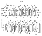
図1A~1Cおよび図2は、本発明に係る分離器の一実施形態を概念的に示すものである。本実施形態の分離器1Aは、天然ガス・油随伴ガスからCO2を透過させる8枚の分離膜2と、これらの分離膜2を重ね合わせる際に該分離膜間に介在設置される7個のシーリング部材3と、重ね合わせた分離膜2の両端に配設される一対の耐圧プレート4と、これらの耐圧プレート間を締結する締結手段5と、両端の分離膜2と耐圧プレート4との間に介在設置されるさらに2個のシーリング部材3-1とを備えている。 Hereinafter, embodiments of the separator according to the present invention will be described in detail.
The separator according to the present invention separates and removes combustible gas such as methane by permeating and removing CO 2 which is a non-combustible gas from natural gas or oil-associated gas, for example, by the separation membrane constituting the separator. It is used for a gas processing plant.
1A to 1C and FIG. 2 conceptually show an embodiment of a separator according to the present invention. Theseparator 1A according to the present embodiment includes eight separation membranes 2 that allow CO 2 to permeate from natural gas and oil-associated gas, and seven pieces that are interposed between the separation membranes 2 when the separation membranes 2 are overlapped. Sealing member 3, a pair of pressure-resistant plates 4 disposed at both ends of the overlapped separation membrane 2, fastening means 5 for fastening between these pressure-resistant plates, and separation membrane 2 and pressure-resistant plates 4 at both ends. Further, two sealing members 3-1 interposed between them are provided.
本発明に係る分離器は、該分離器を構成する分離膜により、例えば、天然ガスや油随伴ガスから非燃焼性ガスであるCO2を透過させて除去し、メタン等の可燃性ガスを分離するガス処理プラントに用いられるものである。
図1A~1Cおよび図2は、本発明に係る分離器の一実施形態を概念的に示すものである。本実施形態の分離器1Aは、天然ガス・油随伴ガスからCO2を透過させる8枚の分離膜2と、これらの分離膜2を重ね合わせる際に該分離膜間に介在設置される7個のシーリング部材3と、重ね合わせた分離膜2の両端に配設される一対の耐圧プレート4と、これらの耐圧プレート間を締結する締結手段5と、両端の分離膜2と耐圧プレート4との間に介在設置されるさらに2個のシーリング部材3-1とを備えている。 Hereinafter, embodiments of the separator according to the present invention will be described in detail.
The separator according to the present invention separates and removes combustible gas such as methane by permeating and removing CO 2 which is a non-combustible gas from natural gas or oil-associated gas, for example, by the separation membrane constituting the separator. It is used for a gas processing plant.
1A to 1C and FIG. 2 conceptually show an embodiment of a separator according to the present invention. The
それぞれの分離膜2は、略矩形状かつ平板状に形成され、両端では3つの孔を対角の4角のうち3か所に有する。また、両端を除く中間に位置する分離膜2のそれぞれは、後述するような4つの孔を対角の4角に、すなわちその上下端部2a,2bの左右両端寄りに有している。この4つの孔のうち、一方の対角にある2つの孔を、後述する非透過ガスを通過させるための非透過ガス孔6とし、他方の対角にある2つの孔を、透過ガスを通過させるための透過ガス孔7としている。両端の分離膜2-1を除くいずれの分離膜2も、同じ形状のものであり、共通化を図ることができるものである。
Each of the separation membranes 2 is formed in a substantially rectangular shape and a flat plate shape, and has three holes at three ends of the diagonal four corners at both ends. Further, each of the separation membranes 2 located in the middle excluding both ends has four holes as described later at the diagonal four corners, that is, near the left and right ends of the upper and lower end portions 2a and 2b. Of these four holes, two holes on one diagonal are made non-permeable gas holes 6 for allowing a non-permeable gas to be described later to pass through, and two holes on the other diagonal are passed through the permeated gas. The permeated gas hole 7 is used. All of the separation membranes 2 except for the separation membranes 2-1 at both ends have the same shape and can be shared.
なお、分離膜2は、例えば、無機多孔体の細孔内に、エトキシ基又はメトキシ基を含むアルコキシシランの加水分解を経て得られたシリカゲルを担持することによって得られる耐酸性複合分離膜、あるいは、アルミナ、シリカ、ジルコニア、チタニアのようなセラミック基材等の多孔質基材から形成することが好ましく、要は、無機質のものであって、主にCO2を透過させる作用を有するものであればいずれでも良い。但し、CO2以外の非可燃性成分を分離したい場合には、その非可燃性成分を透過できるように形成した分離膜2を採用するのは勿論である。
The separation membrane 2 is, for example, an acid-resistant composite separation membrane obtained by supporting silica gel obtained through hydrolysis of an alkoxysilane containing an ethoxy group or a methoxy group in the pores of the inorganic porous body, or It is preferably formed from a porous substrate such as a ceramic substrate such as alumina, silica, zirconia, and titania. In short, it should be made of an inorganic material and mainly has a function of permeating CO 2. Either is fine. However, when it is desired to separate nonflammable components other than CO 2 , it is a matter of course that the separation membrane 2 formed so as to be able to permeate the nonflammable components is employed.
シーリング部材3は、分離膜2の輪郭形状に沿った環状の外側シール部3aと、その一方の対角に一対の環状の内側シール部3b,3bを有している。シーリング部材3の外側シール部3aおよび内側シール部3bとも、断面円形状のものが好適であるが、断面形状は特に限定されない。シーリング部材3は、8枚の分離膜2それぞれ間と耐圧プレート4との間に介在されるもので、本実施形態では9個使用されるが、両端のシーリング部材3-1を除いていずれも同じ形状のものであり、共通化を図ることができるものである。なお、シーリング部材3は、気体透過性が低い弾力のある樹脂等(例えば、ニトリルゴム、ブチルゴム)によって形成されるのが好ましいが、要はシール効果を発揮するものであれば何れでも良く、とくに限定されない。
The sealing member 3 has an annular outer seal portion 3a along the contour shape of the separation membrane 2, and a pair of annular inner seal portions 3b, 3b at one diagonal. The outer seal portion 3a and the inner seal portion 3b of the sealing member 3 are preferably circular in cross section, but the cross sectional shape is not particularly limited. Nine sealing members 3 are interposed between each of the eight separation membranes 2 and the pressure-resistant plate 4. In this embodiment, nine sealing members 3 are used, except for the sealing members 3-1 at both ends. They have the same shape and can be shared. The sealing member 3 is preferably formed of an elastic resin having low gas permeability (for example, nitrile rubber or butyl rubber), but any material that exhibits a sealing effect may be used. It is not limited.
耐圧プレート4は、一方の側部寄りに上下に並んで後述する2つの孔を有するとともに、その4角に後述する締結手段5が設置されるための4つの孔4cを有している(図1A参照)。耐圧プレート4は、左右両端に配置されるもので、左側の耐圧プレート4は向かって右側寄りに、上側に非透過ガス流通孔4aを有し、下側に透過ガス流通孔4bを有する。右側の耐圧プレート4は、向かって右側寄りに、上側に透過ガス流通孔4bを有し、下側に非透過ガス流通孔4aを有する。左右の耐圧プレート4は、同じ形状のものであり、共通化を図ることができるものである。
The pressure-resistant plate 4 has two holes, which will be described later, lined up and down near one side, and four holes 4c for installing fastening means 5, which will be described later, at four corners thereof (see FIG. 1A). The pressure-resistant plates 4 are arranged at both left and right ends, and the left pressure-resistant plate 4 has a non-permeate gas flow hole 4a on the upper side and a permeate gas flow hole 4b on the lower side. The pressure plate 4 on the right side has a permeate gas flow hole 4b on the upper side and a non-permeate gas flow hole 4a on the lower side toward the right side. The left and right pressure-resistant plates 4 have the same shape and can be shared.
締結手段5は、両端にネジ部が形成された直線状のボルト5aと、両端のネジ部に締結されるナット5b,5bから構成されている。締結手段5は、このボルト5aのネジ部を両側の耐圧プレート4の孔4cに挿通して、これらのネジ部にナット5b,5bを締結することにより、耐圧プレート4,4間において、8枚の分離膜2を後述するように重ね合わせたものを固定することができる。
The fastening means 5 is composed of linear bolts 5a having screw portions formed at both ends, and nuts 5b and 5b fastened to the screw portions at both ends. The fastening means 5 inserts the screw portions of the bolts 5a into the holes 4c of the pressure plate 4 on both sides, and fastens the nuts 5b and 5b to these screw portions, so that eight pieces are provided between the pressure plates 4 and 4. These separation membranes 2 can be fixed in a superposed manner as will be described later.
本実施形態では、分離膜2とシーリング部材3を交互に重ね合わせ、それらの両端に耐圧プレート4,4を配置し、締結手段5のナット5b,5bを締めることに固定することができる。このとき、ナット5b,5bを締めるに従い、耐圧プレート4,4を介して、この重ね合された8枚の分離膜2と9個のシーリング部材3をそれらの重ね合わせ方向に圧縮力を加えることができる。この圧縮力により、8枚の分離膜2のそれぞれ間と耐圧プレート4,4との間において後述するようにシール効果が発揮される。
In this embodiment, the separation membrane 2 and the sealing member 3 are alternately overlapped, pressure- resistant plates 4 and 4 are disposed at both ends thereof, and can be fixed by tightening the nuts 5b and 5b of the fastening means 5. At this time, as the nuts 5b and 5b are tightened, a compression force is applied to the eight separation membranes 2 and the nine sealing members 3 through the pressure- resistant plates 4 and 4 in the overlapping direction. Can do. By this compressive force, a sealing effect is exhibited between each of the eight separation membranes 2 and between the pressure- resistant plates 4 and 4 as described later.
また同時に、上記のように各分離膜2と各シーリング部材3と耐圧プレート4,4を固定したことにより、それぞれ隣合う分離膜2,2間にシーリング部材3の外側シール部3aによって外部に対して隔絶された非透過ガス室8と透過ガス室9が分離膜2の重ね合わせ方向に交互に形成される。このとき、シーリング部材3は、その重ね合わせ方向に交互にそれらの向きが左右逆になるように配置されている。すなわち、シーリング部材3の対角の内側シール部3b,3bの位置は、重ね合わせ方向に交互に入れ替わるように配置されている。
At the same time, by fixing each separation membrane 2, each sealing member 3, and pressure- resistant plates 4, 4 as described above, the outer sealing portion 3 a of the sealing member 3 is connected to the outside between the adjacent separation membranes 2, 2. Separated non-permeate gas chambers 8 and permeate gas chambers 9 are alternately formed in the overlapping direction of the separation membrane 2. At this time, the sealing members 3 are arranged so that their directions are alternately reversed left and right in the overlapping direction. That is, the positions of the diagonal inner seal portions 3b, 3b of the sealing member 3 are arranged so as to be alternately switched in the overlapping direction.
ここで、非透過ガス室8は、非透過ガスが流入・流出される空間であり、透過ガス室9は、透過ガスが流入・流出される空間である。そして、それぞれの分離膜2の上端部2aに配設されている非透過ガス孔6を、非透過ガス室8に非透過ガスを流入させる非透過ガス流入孔6aとし、その上端部2aに配設されている透過ガス孔7を、透過ガス室9に透過ガスを流入させる透過ガス流入孔7aとしている。また、それぞれの分離膜2の下端部2bに配設されている非透過ガス孔6を、非透過ガス室8から非透過ガスを流出させる非透過ガス流出孔6bとし、その下端部2bに配設されている透過ガス孔7を、透過ガス室9に透過ガスを流入させる透過ガス流出孔7bとしている。
Here, the non-permeate gas chamber 8 is a space into which non-permeate gas flows in and out, and the permeate gas chamber 9 is a space into which permeate gas flows in and out. Then, the non-permeate gas hole 6 disposed in the upper end 2a of each separation membrane 2 is a non-permeate gas inflow hole 6a through which the non-permeate gas flows into the non-permeate gas chamber 8, and is arranged in the upper end 2a. The permeated gas hole 7 provided is a permeated gas inflow hole 7 a for allowing the permeated gas to flow into the permeated gas chamber 9. Further, the non-permeate gas hole 6 disposed in the lower end 2b of each separation membrane 2 is a non-permeate gas outflow hole 6b through which the non-permeate gas flows out from the non-permeate gas chamber 8, and is arranged in the lower end 2b. The permeate gas hole 7 provided is a permeate gas outflow hole 7 b through which the permeate gas flows into the permeate gas chamber 9.
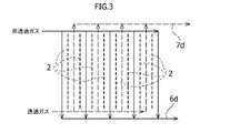
非透過ガス室8のそれぞれは、図1Aおよび図2に示すように、その両側の分離膜2,2の透過ガス流入孔7a,7a間および透過ガス流出孔7b,7b間の連絡通路7c,7cに対して、シーリング部材3の内側シール部3b,3bにより隔絶されている。また、透過ガス室9のそれぞれは、その両側の分離膜2,2の非透過ガス流入孔6a,6a間および非透過ガス流出孔6b,6b間の連絡通路6c,6cに対して、シーリング部材3の内側シール部3b,3bにより隔絶されている。これにより、すべての非透過ガス流入孔6a、非透過ガス室8および非透過ガス流出孔6bによって非透過ガス流路6dが形成されるとともに、すべての透過ガス流入孔7a、透過ガス室9および透過ガス流出孔7bによって透過ガス流路7dが形成される。本実施形態では、この透過ガス流路7dには、必要に応じて、スイープガスを流し、該スイープガスにより透過ガスを送り出すようにしている。
As shown in FIG. 1A and FIG. 2, each of the non-permeate gas chambers 8 has a communication passage 7c between the permeate gas inflow holes 7a and 7a and between the permeate gas outflow holes 7b and 7b of the separation membranes 2 and 2 on both sides thereof. 7c is isolated by the inner seal portions 3b, 3b of the sealing member 3. Each of the permeate gas chambers 9 is a sealing member with respect to the communication passages 6c and 6c between the non-permeate gas inflow holes 6a and 6a and the non-permeate gas outflow holes 6b and 6b of the separation membranes 2 and 2 on both sides thereof. 3 are separated by inner seal portions 3b, 3b. Thereby, the non-permeate gas flow path 6d is formed by all the non-permeate gas inflow holes 6a, the non-permeate gas chambers 8 and the non-permeate gas outflow holes 6b, and all the permeate gas inflow holes 7a, the permeate gas chambers 9 and A permeate gas flow path 7d is formed by the permeate gas outflow hole 7b. In the present embodiment, a sweep gas is allowed to flow through the permeate gas flow path 7d as necessary, and the permeate gas is sent out by the sweep gas.
本実施形態では、上記説明から既に明らかなように、すべの非透過ガス室8における非透過ガス流入孔6aは分離膜2の同じ側である上端部2aに位置され、すべての非透過ガス流出孔6bが分離膜2の同じ側である下端部2bに位置されている。同時に、すべの透過ガス室9における透過ガス流入孔7aは分離膜2の同じ側の下端部2bに位置され、すべての透過ガス流出孔7bは分離膜2の同じ側の上端部2aに位置されている。これにより、すべての非透過ガス室8内における非透過ガスの流れ方向は同じ方向となり(いわゆる並流)、分離膜2の下端部2b側へ、すなわち、図1Aにおいて下方へ向かう流れとなる。同時に、すべての透過ガス室9内における透過ガスの流れ方向は同じ方向となり(いわゆる並流)、分離膜2の上端部2a側へ、すなわち、図1Aにおいて上方へ向かう流れとなる。なお、非透過ガス流入孔6aを分離膜2の下端部2bに位置させ、非透過ガス流出孔6bを上端部2aに位置させ、透過ガス流入孔7aを分離膜2の上端部2aに位置させ、透過ガス流出孔7bは分離膜2の同じ側の下端部2bに位置させるようにしても勿論良い。
In the present embodiment, as is apparent from the above description, the non-permeate gas inflow holes 6a in all the non-permeate gas chambers 8 are located at the upper end 2a on the same side of the separation membrane 2, and all non-permeate gas outflows are performed. The hole 6b is located at the lower end 2b on the same side of the separation membrane 2. At the same time, the permeate gas inflow holes 7a in all the permeate gas chambers 9 are located at the lower end 2b on the same side of the separation membrane 2, and all the permeate gas outflow holes 7b are located at the upper end 2a on the same side of the separation membrane 2. ing. As a result, the flow direction of the non-permeate gas in all the non-permeate gas chambers 8 becomes the same direction (so-called co-current flow), and flows toward the lower end 2b side of the separation membrane 2, that is, downward in FIG. 1A. At the same time, the flow direction of the permeate gas in all the permeate gas chambers 9 is the same direction (so-called parallel flow), and flows toward the upper end 2a of the separation membrane 2, that is, upward in FIG. 1A. The non-permeate gas inflow hole 6a is located at the lower end 2b of the separation membrane 2, the non-permeate gas outflow hole 6b is located at the upper end 2a, and the permeate gas inflow hole 7a is located at the upper end 2a of the separation membrane 2. Of course, the permeate gas outflow hole 7b may be positioned at the lower end 2b on the same side of the separation membrane 2.
したがって、本実施形態では、すべての非透過ガス室8内における非透過ガスの流れ方向は、すべての透過ガス室9内における透過ガスの流れ方向と反対の方向(いわゆる向流)となっている。このような隣合う非透過ガス室8と透過ガス室9内の流れが完全向流となっているため、透過ガスの濃度に起因する透過率の低下を防止することができる。さらには、分離膜を複数重ねてスケールアップした場合にも一定流速の設計が可能である。また、両端以外は分離膜2とシールリング部材3の形状が同じであり、共通化でき、部品の種類数を最小化できる。
Therefore, in this embodiment, the flow direction of the non-permeate gas in all the non-permeate gas chambers 8 is a direction opposite to the flow direction of the permeate gas in all the permeate gas chambers 9 (so-called countercurrent). . Since the flows in the adjacent non-permeating gas chamber 8 and the permeating gas chamber 9 are completely counterflow, it is possible to prevent a decrease in the transmittance due to the concentration of the permeating gas. Furthermore, a constant flow rate can be designed even when a plurality of separation membranes are stacked and scaled up. Moreover, the shapes of the separation membrane 2 and the seal ring member 3 are the same except for both ends, and can be made common, and the number of types of parts can be minimized.
また、本実施形態では、上記した8枚の分離膜2を積層した構成としたことにより、要求される分離性能に応じて大型化が容易であり、その組立性も良好であり、いずれかの分離膜2が破損した場合でも、その破損した一部の分離膜の交換だけで済むので、経済的であり、メンテナンスが容易である。
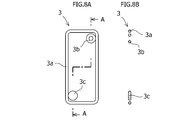
なお、本実施形態の場合、両端の分離膜2-1として4つの孔を設けたものを採用しても勿論良い。この場合は、後述の図7に示した実施形態のように、不要な孔を封じるための円盤状シール部3cを設けたシーリング部材3-1を採用すれば良い。本発明でいう両端の分離膜2-1に限っては、4つの孔とは、場合により3つの孔であっても良いことを意味している。 Moreover, in this embodiment, since it was set as the structure which laminated | stacked eight saidseparation membranes 2, according to the isolation | separation performance requested | required, the enlargement is easy and the assemblability is also favorable, Even when the separation membrane 2 is damaged, it is only necessary to replace the damaged part of the separation membrane, which is economical and easy to maintain.
In the case of the present embodiment, it is of course possible to employ one having four holes as the separation membrane 2-1 at both ends. In this case, as in the embodiment shown in FIG. 7 described later, a sealing member 3-1 provided with a disk-shapedseal portion 3c for sealing unnecessary holes may be employed. In the present invention, only the separation membrane 2-1 at both ends means that the four holes may be three holes in some cases.
なお、本実施形態の場合、両端の分離膜2-1として4つの孔を設けたものを採用しても勿論良い。この場合は、後述の図7に示した実施形態のように、不要な孔を封じるための円盤状シール部3cを設けたシーリング部材3-1を採用すれば良い。本発明でいう両端の分離膜2-1に限っては、4つの孔とは、場合により3つの孔であっても良いことを意味している。 Moreover, in this embodiment, since it was set as the structure which laminated | stacked eight said
In the case of the present embodiment, it is of course possible to employ one having four holes as the separation membrane 2-1 at both ends. In this case, as in the embodiment shown in FIG. 7 described later, a sealing member 3-1 provided with a disk-shaped
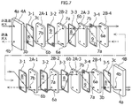
次に、図4A~4C、図5および図6を参照しながら、本発明に係る分離器の他の実施形態について説明する。本実施形態の分離器1Bを構成する要素は、上記実施形態の分離器1Aを構成する要素と機能が同じであるため、同一機能を有する要素については同一符号を付し、その詳細な説明を省略する。
本実施形態による分離器1Bは、上記した一実施形態に係る分離器1Aとほぼ同様に、8枚の分離膜2と、これらの分離膜2を重ね合わせる際に該分離膜間に介在設置される9個のシーリング部材3と、重ね合わせた分離膜2の両端に配設される一対の耐圧プレート4A,4Bと、これらの耐圧プレート間を締結する締結手段5とを備えている。 Next, another embodiment of the separator according to the present invention will be described with reference to FIGS. 4A to 4C, FIGS. 5 and 6. FIG. The elements constituting theseparator 1B of the present embodiment have the same functions as those of the elements constituting the separator 1A of the above embodiment. Therefore, elements having the same functions are denoted by the same reference numerals, and detailed descriptions thereof are given. Omitted.
Theseparator 1B according to the present embodiment is installed in the same manner as the separator 1A according to the above-described embodiment, with eight separation membranes 2 interposed between the separation membranes 2 when the separation membranes 2 are overlapped. Nine sealing members 3, a pair of pressure- resistant plates 4 A and 4 B disposed at both ends of the overlapped separation membrane 2, and fastening means 5 for fastening the pressure-resistant plates to each other.
本実施形態による分離器1Bは、上記した一実施形態に係る分離器1Aとほぼ同様に、8枚の分離膜2と、これらの分離膜2を重ね合わせる際に該分離膜間に介在設置される9個のシーリング部材3と、重ね合わせた分離膜2の両端に配設される一対の耐圧プレート4A,4Bと、これらの耐圧プレート間を締結する締結手段5とを備えている。 Next, another embodiment of the separator according to the present invention will be described with reference to FIGS. 4A to 4C, FIGS. 5 and 6. FIG. The elements constituting the
The
分離膜2としては、略矩形状かつ平板状に形成され、2つの孔を上端部2aに形成した分離膜2Aと、2つの孔を一側寄りに上下端部2a,2bに形成した分離膜2Bが用いられている。分離膜2A,2Bとも、それらの2つの孔のうち、一方の孔を、後述するように、非透過ガスを通過させるための非透過ガス孔6とし、他方の孔を、透過ガスを通過させるための透過ガス孔7としている。それぞれの分離膜2A,2Bは、同じ形状のものであり、共通化を図ることができるものである。なお、分離膜2A,2Bは、上記した一実施形態に係る分離器1Aの分離膜2と同様な材料によって形成されるものである。
As the separation membrane 2, a separation membrane 2 </ b> A formed in a substantially rectangular and flat shape and having two holes formed in the upper end portion 2 a, and a separation membrane formed in the upper and lower end portions 2 a and 2 b closer to one side. 2B is used. In both of the separation membranes 2A and 2B, as will be described later, one of the two holes is a non-permeable gas hole 6 for allowing the non-permeable gas to pass therethrough, and the other hole is allowed to pass the permeable gas. The permeate gas hole 7 is used. Each of the separation membranes 2A and 2B has the same shape and can be shared. The separation membranes 2A and 2B are formed of the same material as the separation membrane 2 of the separator 1A according to the above-described embodiment.
シーリング部材3は、分離膜2A,2Bの輪郭形状に沿った環状の外側シール部3aと、その一角に1つの内側シール部3bを有している。シーリング部材3の外側シール部3aおよび内側シール部3bとも、断面円形状のものが好適であるが、断面形状は特に限定されない。これらのシーリング部材3のそれぞれは、8枚の分離膜2それぞれ間と耐圧プレート4との間に介在されるもので、本実施形態では9個使用されるが、いずれも同じ形状のものであり、共通化を図ることができるものである。なお、シーリング部材3は、上記した一実施形態に係る分離器1Aのシーリング部材3と同様な材料によって形成されるものである。
The sealing member 3 has an annular outer seal portion 3a along the contour shape of the separation membranes 2A and 2B, and one inner seal portion 3b at one corner. The outer seal portion 3a and the inner seal portion 3b of the sealing member 3 are preferably circular in cross section, but the cross sectional shape is not particularly limited. Each of these sealing members 3 is interposed between each of the eight separation membranes 2 and between the pressure-resistant plates 4 and is used in this embodiment, but all of them have the same shape. , It can be shared. The sealing member 3 is made of the same material as the sealing member 3 of the separator 1A according to the above-described embodiment.
耐圧プレート4としては、一方の側部寄りに上下に並べて後述する2つの孔を形成した耐圧プレート4Aと、図4Aにおいて下端部寄りに水平に並べて後述する2つの孔を形成した耐圧プレート4Bが採用される。耐圧プレート4A,4Bは、上記一実施形態に係る耐圧プレート4と同様に、いずれもその4角に締結手段5が設置されるための4つの孔4cを有している(図4A参照)。耐圧プレート4Aは、図4Aにおいて左端に配置され、耐圧プレート4Bは、図4Aにおいて右端に配置される。耐圧プレート4Aの2つの孔は、向かって右側寄りに形成され、そのうちの上側の孔を非透過ガス流通孔4aとし、下側の孔を透過ガス流通孔4bとしている。耐圧プレート4Bの2つの孔は、向かって下側寄りに形成され、そのうちの右側の孔を透過ガス流通孔4bとし、左側の孔を非透過ガス流通孔4aとしている。
As the pressure plate 4, there are a pressure plate 4 </ b> A in which two holes to be described later are formed side by side near one side and a pressure plate 4 </ b> B in which two holes to be described later are formed horizontally in FIG. Adopted. Each of the pressure plates 4A and 4B has four holes 4c for the fastening means 5 to be installed at the four corners thereof as in the case of the pressure plate 4 according to the above-described embodiment (see FIG. 4A). The pressure plate 4A is disposed at the left end in FIG. 4A, and the pressure plate 4B is disposed at the right end in FIG. 4A. The two holes of the pressure-resistant plate 4A are formed on the right side, and the upper hole is a non-permeate gas flow hole 4a and the lower hole is a permeate gas flow hole 4b. The two holes of the pressure-resistant plate 4B are formed on the lower side of the pressure plate 4B, and the right-hand hole is a permeate gas flow hole 4b and the left-hand hole is a non-permeate gas flow hole 4a.
締結手段5は、上記した一実施形態に係る分離器1Aのものと、構成・作用・機能が全く同じであるので、その詳細な説明を省略する。なお、以下の説明にあたっては、便宜上、重ね合わされる分離膜2およびシーリング部材3について、図5において左側から、それらの符号を、2A-1、2B-2、2A-3、2B-4、3-1、3-2、3-3、3-4、3-5と付して説明する。
Since the fastening means 5 has exactly the same configuration, operation, and function as that of the separator 1A according to the above-described embodiment, a detailed description thereof will be omitted. In the following description, for the sake of convenience, the separation membrane 2 and the sealing member 3 to be overlaid are denoted by 2A-1, 2B-2, 2A-3, 2B-4, 3B from the left side in FIG. -1, 3-2, 3-3, 3-4, and 3-5 will be described.
本実施形態では、図5に示すように、左側から1番目の分離膜2A-1は正立、2番目の分離膜2B-2は正立、3番目の分離膜2A-3は上下反転、4番目の分離膜2B-4は左右反転されており、以降繰り返しこの順に並べられて、後述するように重ね合わされる。同様に、シーリング部材3も、分離膜2A-1、2B-2、2A-3、2B-4に対応して、図5に示すように、左側から1番目のシーリング部材3-1は正立、2番目のシーリング部材3-2は左右反転、3番目のシーリング部材3-3は左右上下反転、4番目のシーリング部材3-4は上下反転されており、以降繰り返しこの順に並べられ、後述するようにそれぞれの分離膜2,2間に介在され、最後の分離膜2B-4と右側の耐圧プレート4Bとの間に、シーリング部材3-5(3-1と同じもの)が介在される。
In the present embodiment, as shown in FIG. 5, the first separation membrane 2A-1 from the left is upright, the second separation membrane 2B-2 is upright, the third separation membrane 2A-3 is upside down, The fourth separation membrane 2B-4 is reversed left and right, and thereafter repeatedly arranged in this order and overlaid as described later. Similarly, the sealing member 3 also corresponds to the separation membranes 2A-1, 2B-2, 2A-3, 2B-4, and as shown in FIG. 5, the first sealing member 3-1 from the left is upright. The second sealing member 3-2 is horizontally reversed, the third sealing member 3-3 is horizontally reversed, and the fourth sealing member 3-4 is vertically reversed. Thus, a sealing member 3-5 (same as 3-1) is interposed between the last separation membrane 2B-4 and the right pressure plate 4B.
本実施形態では、すべての分離膜2とシーリング部材3は、上記したように並べた状態で、締結手段5を用いて、上記一実施形態の場合と同様に圧縮された態様で固定される。この固定された状態においては、左側の耐圧プレート4Aと分離膜2A-1との間の空間に、分離膜2A-1に一部画成された非透過ガス室8が形成され、その隣りに分離膜2A-1と分離膜2B-2の間の空間に透過ガス室9が形成され、その隣りに分離膜2B-2と分離膜2A-3の間の空間に非透過ガス室8が形成され、その隣りに分離膜2A-3と分離膜2B-4の間の空間に透過ガス室9が形成され、以降繰り返しこの順序で形成され、以降繰り返しこの順に並べられ、最後の分離膜2B-4と右側の耐圧プレート4Bとの間の空間に非透過ガス室8が形成されている。
In this embodiment, all the separation membranes 2 and the sealing members 3 are fixed in a compressed state in the same manner as in the above-described one embodiment, using the fastening means 5 in a state where they are arranged as described above. In this fixed state, a non-permeate gas chamber 8 partially defined in the separation membrane 2A-1 is formed in the space between the pressure-resistant plate 4A on the left side and the separation membrane 2A-1, and next to it. A permeate gas chamber 9 is formed in the space between the separation membrane 2A-1 and the separation membrane 2B-2, and a non-permeate gas chamber 8 is formed in the space between the separation membrane 2B-2 and the separation membrane 2A-3 next to it. Next, a permeating gas chamber 9 is formed in the space between the separation membrane 2A-3 and the separation membrane 2B-4 next to it, and thereafter repeatedly formed in this order, and then repeatedly arranged in this order, and the last separation membrane 2B- A non-permeating gas chamber 8 is formed in a space between 4 and the right pressure plate 4B.
さらに、本実施形態では、上記構成としたことにより、分離膜2A-1の非透過ガス孔6を、耐圧プレート4Aと分離膜2A-1との間の非透過ガス室8から非透過ガスを流出させる非透過ガス流出孔6bとして分離膜2A-1の下端部2bに形成しているとともに、分離膜2A-1の透過ガス孔7を、分離膜2A-1と分離膜2B-2との間の透過ガス室9から透過ガスを流出させる透過ガス流出孔7bとして分離膜2A-1の下端部2bに形成している。なお、耐圧プレート4Aと分離膜2A-1との間の非透過ガス室8は、耐圧プレート4Aの透過ガス流通孔4bと分離膜2A-1の透過ガス流出孔7bとの間の連絡通路7c(図4Aおよび図5参照)に対して、シーリング部材3-1の内側シール部3bにより隔絶されている。
Furthermore, in the present embodiment, the above configuration allows the non-permeating gas hole 6 of the separation membrane 2A-1 to pass through the non-permeating gas from the non-permeating gas chamber 8 between the pressure-resistant plate 4A and the separation membrane 2A-1. A non-permeating gas outflow hole 6b is formed in the lower end 2b of the separation membrane 2A-1, and the permeating gas hole 7 of the separation membrane 2A-1 is formed between the separation membrane 2A-1 and the separation membrane 2B-2. A permeate gas outflow hole 7b through which the permeate gas flows out from the permeate gas chamber 9 is formed in the lower end 2b of the separation membrane 2A-1. The non-permeate gas chamber 8 between the pressure plate 4A and the separation membrane 2A-1 is a communication passage 7c between the permeate gas flow hole 4b of the pressure plate 4A and the permeate gas outflow hole 7b of the separation membrane 2A-1. (See FIGS. 4A and 5), they are isolated by the inner seal portion 3b of the sealing member 3-1.
また、分離膜2B-2の非透過ガス孔6を、分離膜2A-1の非透過流出孔6bに合致させて、分離膜2B-2と分離膜2A-3との間の非透過ガス室8に非透過ガスを流入させる非透過ガス流入孔6aとして、分離膜2B-2の下端部2bに形成するとともに、分離膜2B-2の透過ガス孔7を、分離膜2A-1と分離膜2B-2との間の透過ガス室9に透過ガスを流入させる透過ガス流入孔7aとして分離膜2B-2の上端部2aに形成している。なお、分離膜2A-1と分離膜2B-2との間の透過ガス室9は、分離膜2A-1の非透過ガス流出孔6bと分離膜2B-2の非透過ガス流入孔6aとの間の連絡通路6c(図4Aおよび図5参照)に対して、シーリング部材3-2の内側シール部3bにより隔絶されている。
Further, the non-permeating gas hole 6 between the separation membrane 2B-2 and the separation membrane 2A-3 is formed by matching the non-permeating gas hole 6 of the separation membrane 2B-2 with the non-permeating outflow hole 6b of the separation membrane 2A-1. 8 is formed in the lower end portion 2b of the separation membrane 2B-2 as a non-permeate gas inflow hole 6a for allowing the non-permeate gas to flow in, and the permeation gas hole 7 of the separation membrane 2B-2 is formed between the separation membrane 2A-1 and the separation membrane. A permeate gas inflow hole 7a for allowing permeate gas to flow into the permeate gas chamber 9 between 2B-2 is formed at the upper end 2a of the separation membrane 2B-2. The permeate gas chamber 9 between the separation membrane 2A-1 and the separation membrane 2B-2 is formed between the non-permeate gas outflow hole 6b of the separation membrane 2A-1 and the non-permeate gas inflow hole 6a of the separation membrane 2B-2. The communication path 6c between them (see FIGS. 4A and 5) is isolated by the inner seal portion 3b of the sealing member 3-2.
さらに、分離膜2A-3の非透過ガス孔6を、分離膜2B-2と分離膜2A-3との間の非透過ガス室8から非透過ガスを流出させる非透過ガス流出孔6bとして、分離膜2A-3の上端部2aに形成するとともに、分離膜2A-3の透過ガス孔7を、分離膜2B-2の透過ガス流入孔7aに合致させて、分離膜2A-3と分離膜2B-4との間の透過ガス室9から透過ガスを流出させる透過ガス流出孔7bとして分離膜2A-3の上端部2aに形成している。なお、分離膜2B-2と分離膜2A-3との間の非透過ガス室8は、分離膜2B-2の透過ガス流入孔7aと分離膜2A-3の透過ガス流出孔7bとの間の連絡通路7c(図4Aおよび図5参照)に対して、シーリング部材3-3の内側シール部3bにより隔絶されている。
Further, the non-permeate gas hole 6 of the separation membrane 2A-3 is used as a non-permeate gas outflow hole 6b through which the non-permeate gas flows out from the non-permeate gas chamber 8 between the separation membrane 2B-2 and the separation membrane 2A-3. The separation membrane 2A-3 and the separation membrane are formed at the upper end 2a of the separation membrane 2A-3, and the permeation gas holes 7 of the separation membrane 2A-3 are aligned with the permeation gas inflow holes 7a of the separation membrane 2B-2. A permeate gas outflow hole 7b for allowing permeate gas to flow out of the permeate gas chamber 9 between 2B-4 is formed at the upper end 2a of the separation membrane 2A-3. The non-permeate gas chamber 8 between the separation membrane 2B-2 and the separation membrane 2A-3 is between the permeate gas inflow hole 7a of the separation membrane 2B-2 and the permeate gas outflow hole 7b of the separation membrane 2A-3. The communication passage 7c (see FIGS. 4A and 5) is isolated by the inner seal portion 3b of the sealing member 3-3.
さらにまた、分離膜2B-4の非透過ガス孔6を、分離膜2A-3の非透過ガス流出孔6bに合致させて、次の分離膜2A-1と分離膜2B-4との間の非透過ガス室8に非透過ガスを流入させる非透過ガス流入孔6aとして、分離膜2B-4の上端部2aに形成するとともに、分離膜2B-4の透過ガス孔7を、分離膜2A-3と分離膜2B-4との間の透過ガス室9に透過ガスを流入させる透過ガス流入孔7aとして分離膜2B-4の下端部2bに、以降繰り返す次の分離膜2A-1の透過ガス流出孔7bに合致するように形成している。なお、分離膜2A-3と分離膜2B-4との間の透過ガス室9は、分離膜2A-3の非透過ガス流出孔6bと分離膜2B-4の非透過ガス流入孔6aとの間の連絡通路6c(図4A参照)に対して、シーリング部材3-4の内側シール部3bにより隔絶されている(図4Aおよび図5参照)。
Furthermore, the non-permeating gas hole 6 of the separation membrane 2B-4 is matched with the non-permeating gas outflow hole 6b of the separation membrane 2A-3, so that the separation membrane 2A-1 is separated from the next separation membrane 2B-4. A non-permeate gas inflow hole 6a for allowing non-permeate gas to flow into the non-permeate gas chamber 8 is formed at the upper end 2a of the separation membrane 2B-4, and the permeate gas hole 7 of the separation membrane 2B-4 is formed as a separation membrane 2A-. 3 and the permeation gas of the next separation membrane 2A-1 to be repeated at the lower end 2b of the separation membrane 2B-4 as a permeation gas inflow hole 7a for allowing the permeation gas to flow into the permeation gas chamber 9 between the separation membrane 2B-4. It is formed to match the outflow hole 7b. The permeate gas chamber 9 between the separation membrane 2A-3 and the separation membrane 2B-4 is formed between the non-permeate gas outflow hole 6b of the separation membrane 2A-3 and the non-permeate gas inflow hole 6a of the separation membrane 2B-4. The communication path 6c (see FIG. 4A) is isolated by the inner seal portion 3b of the sealing member 3-4 (see FIGS. 4A and 5).
以降、上記と同様の順序で、次の分離膜2A-1~次の分離膜2B-4および、右側の耐圧プレート4Bまでに、同様に構成されるので、その説明を省略する。
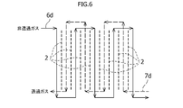
上記構成により、すべての非透過ガス流入孔6a、非透過ガス室8および非透過ガス流出孔6bによって非透過ガス流路6dが形成されるとともに、すべての透過ガス流入孔7a、透過ガス室9および透過ガス流出孔7bによって透過ガス流路7dが形成される(図6参照)。とくに、本実施形態では、この透過ガス流路7dには、必要に応じて、スイープガスを流し、該スイープガスにより透過ガスを送り出すようにしている。 Since thesubsequent separation membrane 2A-1 to the next separation membrane 2B-4 and the right pressure plate 4B are configured in the same order as described above, description thereof will be omitted.
With the above configuration, all the non-permeategas inflow holes 6a, the non-permeate gas chambers 8 and the non-permeate gas outflow holes 6b form a non-permeate gas flow path 6d, and all the permeate gas inflow holes 7a and the permeate gas chambers 9 are formed. A permeate gas flow path 7d is formed by the permeate gas outflow hole 7b (see FIG. 6). In particular, in the present embodiment, a sweep gas is allowed to flow through the permeate gas channel 7d as necessary, and the permeate gas is sent out by the sweep gas.
上記構成により、すべての非透過ガス流入孔6a、非透過ガス室8および非透過ガス流出孔6bによって非透過ガス流路6dが形成されるとともに、すべての透過ガス流入孔7a、透過ガス室9および透過ガス流出孔7bによって透過ガス流路7dが形成される(図6参照)。とくに、本実施形態では、この透過ガス流路7dには、必要に応じて、スイープガスを流し、該スイープガスにより透過ガスを送り出すようにしている。 Since the
With the above configuration, all the non-permeate
本実施形態では、非透過ガス流路6dと透過ガス流路7dを上記したように構成したことから、非透過ガスは、図5において左側の耐圧プレート4Aの非透過ガス流通孔4aを介して導入され、上記した非透過ガス流路6dを流れて、右側の耐圧プレート4Bの非透過ガス流通孔4aから外部に抜けるようになっている。このとき、天然ガス・油随伴ガスに含まれる非可燃性ガス成分である、例えばCO2は、各非透過ガス室8を通過する際に両側の分離膜2を透過して両隣の透過ガス室9,9に移動して透過ガスとなり、透過ガス流路7dを通じて分離される。
In the present embodiment, since the non-permeate gas channel 6d and the permeate gas channel 7d are configured as described above, the non-permeate gas passes through the non-permeate gas flow hole 4a of the left pressure plate 4A in FIG. It is introduced and flows through the above-described non-permeate gas passage 6d so as to come out from the non-permeate gas flow hole 4a of the right pressure-resistant plate 4B. At this time, for example, CO 2 , which is a non-combustible gas component contained in the natural gas / oil-associated gas, passes through the separation membranes 2 on both sides when passing through each non-permeate gas chamber 8, and the adjacent permeate gas chambers. It moves to 9, 9 and becomes permeate gas, and is separated through permeate gas channel 7d.
本実施形態では、上記したように、スイープガスを利用する場合は、スイープガスを右側の耐圧プレート4Bの透過ガス流通孔4bを通じて導入され、透過ガス流路7dを流れて、左側の耐圧プレート4Aの透過ガス流通孔4bから外部に抜くことができる。スイープガスを用いることにより、各透過ガス室9を通過する際に両側の分離膜2を透過してきた透過ガスを効率的に補足して外部に送り出すことができる。さらには、処理容量等に応じて分離膜枚数が複数になった場合においても透過側、非透過側ともワンスルーであり流量分配を考慮する必要ない。また、前記の実施形態の分離器1Aのように並列に構成した場合に比べて、高流速であるため濃度分極を回避でき、高い透過性能を得ることができる。
In the present embodiment, as described above, when the sweep gas is used, the sweep gas is introduced through the permeate gas flow hole 4b of the right pressure plate 4B, flows through the permeate gas flow path 7d, and flows through the left pressure plate 4A. The permeate gas circulation holes 4b can be extracted outside. By using the sweep gas, the permeate gas that has permeated through the separation membranes 2 on both sides when passing through each permeate gas chamber 9 can be efficiently captured and sent to the outside. Furthermore, even when the number of separation membranes becomes plural according to the processing capacity and the like, both the permeation side and the non-permeation side are one-through, and there is no need to consider flow distribution. In addition, compared to the case where the separators 1A of the above-described embodiment are configured in parallel, since the flow velocity is high, concentration polarization can be avoided and high permeation performance can be obtained.
また、本実施形態では、上記した8枚の分離膜2を積層した構成としたことにより、要求される分離性能に応じて大型化が容易であり、その組立性も良好であり、いずれかの分離膜が破損した場合でも、その破損した一部の分離膜の交換だけで済むので、経済的であり、メンテナンスが容易である。
Moreover, in this embodiment, since it was set as the structure which laminated | stacked eight said separation membranes 2, according to the isolation | separation performance requested | required, the enlargement is easy and the assemblability is also favorable, Even when the separation membrane is damaged, it is only necessary to replace the damaged part of the separation membrane, which is economical and easy to maintain.
図7、図8Aおよび8Bは、図4A~4Cおよび図5に示した分離器1Bにおいて、分離膜2として4つの孔を有するものを採用した場合について図示したものである。各分離膜2において、不要な孔に対しては、この孔を封じるためにシーリング部材3に円盤状シール部3c(図8Aおよび図8B参照)を設けている。円盤状シール部3cは、内側シール部3bとは反対側の対角に設けられている。このような分離膜2およびシーリング部材3を用いることにより、上記した実施形態のものと同様な分離器1Bを構成することができ、同様な作用効果を奏させることができ、分離膜2の共通化を図ることができる。
7, 8A and 8B illustrate the case where the separator 1B shown in FIGS. 4A to 4C and FIG. 5 employs the separation membrane 2 having four holes. In each separation membrane 2, a disc-shaped seal portion 3 c (see FIGS. 8A and 8B) is provided in the sealing member 3 to seal unnecessary holes for unnecessary holes. The disk-shaped seal portion 3c is provided at a diagonal opposite to the inner seal portion 3b. By using the separation membrane 2 and the sealing member 3 as described above, a separator 1B similar to that of the above-described embodiment can be configured, and the same operational effects can be achieved. Can be achieved.
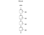
図9は、最初の実施形態に係る分離器1Aを複数並列に接続した構成としたものである。分離器1Aは、すでに説明したように、非透過ガス流路6dと透過ガス流路7dが途中で分岐して並列に流れるように構成されているので、要求される分離性能に応じて、必要な数だけ並列に接続すれば、小型の分離器1Aの場合でも容易に高性能な分離器を構成することができる。同様に、図10は、上記の他の実施形態に係る分離器1Bを複数直列に接続した構成としたものである。分離器1Bは、すでに説明したように、非透過ガス流路6dと透過ガス流路7dが途中で分岐することなく直流的に流れるように構成されているので、要求される分離性能に応じて、必要な数だけ直列に接続すれば、小型の分離器1Bの場合でも容易に高性能な分離器を構成することができる。なお、上記のように分離器1Aを並列接続したものと、分離器1Bを直列に接続したものを組み合わせて構成するようにしても勿論良く、さらに高い分離性能への要求にも対応することが可能である。
FIG. 9 shows a configuration in which a plurality of separators 1A according to the first embodiment are connected in parallel. As described above, the separator 1A is configured such that the non-permeate gas flow path 6d and the permeate gas flow path 7d branch in the middle and flow in parallel, so that it is necessary depending on the required separation performance. If a large number are connected in parallel, a high-performance separator can be easily configured even in the case of the small separator 1A. Similarly, FIG. 10 shows a configuration in which a plurality of separators 1B according to the other embodiments are connected in series. As described above, the separator 1B is configured so that the non-permeating gas flow path 6d and the permeating gas flow path 7d flow in a DC manner without branching on the way, so that according to the required separation performance. If the required number is connected in series, a high-performance separator can be easily configured even in the case of the small separator 1B. Of course, it may be configured by combining the separator 1A connected in parallel and the separator 1B connected in series as described above, and can meet the demand for higher separation performance. Is possible.
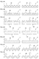
図11A~11G及び図12は、上記両実施形態は勿論のこと、いずれの分離器においても使用可能な分離膜2の他の例を示すものである。図11A~11Eは、分離膜2の表面にストライプ状の溝(あるいは凸凹)10を形成したものを示し、図11Fおよび11Gは、分離膜2自体の断面を波形形状としたものを示している。図11Aは断面山形の段付き溝10を形成したものを示し、図11Bは断面が矩形状の溝10を形成したものを示し、図11Cは分離膜の両面に図11Bに示した溝10を形成したものを示し、図11Dは分離膜2の両面に図11Bに示した溝10を、該溝の幅の分だけずらして形成したものを示し、図11Eは一面を断面さざ波形状の溝10を形成したものを示し、図11Fは断面を角ばった波形形状にした分離膜2を示し、図11Gは断面を緩い丸形の波形形状とした分離膜2を示すものである。
FIGS. 11A to 11G and FIG. 12 show other examples of the separation membrane 2 that can be used in any separator as well as the above-described embodiments. 11A to 11E show the separation membrane 2 having a striped groove (or unevenness) 10 formed on the surface thereof, and FIGS. 11F and 11G show the separation membrane 2 itself having a corrugated cross section. . 11A shows a stepped groove 10 having a mountain-shaped section, FIG. 11B shows a groove 10 having a rectangular cross section, and FIG. 11C shows the groove 10 shown in FIG. 11B on both sides of the separation membrane. FIG. 11D shows a structure in which the groove 10 shown in FIG. 11B is formed on both surfaces of the separation membrane 2 by shifting by the width of the groove, and FIG. 11E shows a groove 10 having one surface with a ripple shape in cross section. FIG. 11F shows the separation membrane 2 having a corrugated shape with a square cross section, and FIG. 11G shows the separation membrane 2 having a loose round corrugated shape.
なお、図11A~11Gにおいて、左側に示した図は、溝10に対して直角方法に非透過ガスまたは透過ガスが流れる様子を示したもので、右側に示した図は、溝10に対して該溝の形成方向、すなわち、左側に示した図の場合と直角の方向に非透過ガスまたは透過ガスが流れる様子を示したものである。なお、非透過ガスまたは透過ガスを流す方向はいずれの方向でも良く、また、隣合う非透過ガス流路と透過ガス流路においては、溝10の方向が互いに方向が直角になるようにすることもできるが、とくに限定されるものではない。
11A to 11G, the diagrams shown on the left side show how the non-permeate gas or the permeate gas flows in a direction perpendicular to the groove 10, and the diagrams on the right side show the groove 10 It shows a state in which a non-permeate gas or a permeate gas flows in a direction in which the groove is formed, that is, in a direction perpendicular to the case shown in the left side. The direction in which the non-permeate gas or the permeate gas flows may be any direction, and in the adjacent non-permeate gas channel and the permeate gas channel, the directions of the grooves 10 are perpendicular to each other. However, it is not particularly limited.
上記したように、分離膜2を構成することにより、分離膜2の表面積を大きくでき、その表面の流れにおける乱流も促進されることから、その透過性能を大幅に向上させることができる。また、図11Fおよび11Gに示したような分離膜2では、分離膜2の厚さをその幅方向に渡って均一にすることができ、分離膜の製造が容易になる。
As described above, by configuring the separation membrane 2, the surface area of the separation membrane 2 can be increased, and turbulent flow in the surface flow can be promoted, so that the permeation performance can be greatly improved. Further, in the separation membrane 2 as shown in FIGS. 11F and 11G, the thickness of the separation membrane 2 can be made uniform in the width direction, and the production of the separation membrane is facilitated.
図12A~12Cは、分離膜2の両面に、形成方向が互いに直交する凹凸の溝10を設けた場合の例を示したものであり、このような構成とすることにより、膜強度の向上をはかることができる。
12A to 12C show an example in which concave and convex grooves 10 whose formation directions are orthogonal to each other are provided on both surfaces of the separation membrane 2. By adopting such a configuration, the membrane strength can be improved. Can measure.
なお、上記両実施形態では、非透過ガス孔および透過ガス孔を形成する場所を分離膜2の上端部2aまたは下端部2bとしたが、本発明はこれに限らず、分離膜の上下端部でないその他の一端部または他端部であっても良い。本発明では、上端部(または一端部)と下端部(他端部)は、言葉通り厳密に、分離膜の上端部(または一端部)および下端部(または他端部)を意味するものでなく、要は互いに適宜離れた適当な箇所であれば良く、分離膜の形状によっては、必ずしも分離膜の上端部(または一端部)および下端部(または他端部)でなくとも良い。
また、本発明では、分離膜に形成する孔の数は特に限定されないが、好ましくは、孔の数が偶数であれば良い。偶数の孔を設けた場合は分離膜の共通化を図ることができるメリットがある。この場合、両端の分離膜のように奇数の孔で済む場合は、前述したように、偶数の孔のうちの不要な孔を、シーリング部材に円盤状シール部を設けて封じれば良い。勿論、奇数の孔を設けた分離膜を別途形成するようにしても良い。
さらに、上記両実施形態では、分離膜に形成する孔およびシーリング部材の内側シール部および円盤状シール部を対角の角部に形成するようにしたが、その形成場所も特に限定されず、要は、分離膜の孔の位置に合わせて適宜形成されれば良い。 In both the above-described embodiments, the location where the non-permeating gas hole and the permeating gas hole are formed is theupper end 2a or the lower end 2b of the separation membrane 2. However, the present invention is not limited to this, and the upper and lower ends of the separation membrane. Other one end or the other end may not be used. In the present invention, the upper end portion (or one end portion) and the lower end portion (the other end portion) strictly mean the upper end portion (or one end portion) and the lower end portion (or the other end portion) of the separation membrane. In short, it may be an appropriate place that is appropriately separated from each other, and depending on the shape of the separation membrane, it may not necessarily be the upper end (or one end) and the lower end (or the other end) of the separation membrane.
In the present invention, the number of holes formed in the separation membrane is not particularly limited, but preferably the number of holes may be an even number. Providing an even number of holes is advantageous in that the separation membrane can be shared. In this case, when an odd number of holes is sufficient as in the separation membranes at both ends, as described above, unnecessary holes out of the even number of holes may be sealed by providing a disk-shaped seal portion on the sealing member. Of course, a separation membrane provided with an odd number of holes may be formed separately.
Furthermore, in both of the above embodiments, the hole formed in the separation membrane and the inner seal portion and the disc-shaped seal portion of the sealing member are formed at the diagonal corners, but the formation location is not particularly limited and is required. May be appropriately formed in accordance with the position of the hole of the separation membrane.
また、本発明では、分離膜に形成する孔の数は特に限定されないが、好ましくは、孔の数が偶数であれば良い。偶数の孔を設けた場合は分離膜の共通化を図ることができるメリットがある。この場合、両端の分離膜のように奇数の孔で済む場合は、前述したように、偶数の孔のうちの不要な孔を、シーリング部材に円盤状シール部を設けて封じれば良い。勿論、奇数の孔を設けた分離膜を別途形成するようにしても良い。
さらに、上記両実施形態では、分離膜に形成する孔およびシーリング部材の内側シール部および円盤状シール部を対角の角部に形成するようにしたが、その形成場所も特に限定されず、要は、分離膜の孔の位置に合わせて適宜形成されれば良い。 In both the above-described embodiments, the location where the non-permeating gas hole and the permeating gas hole are formed is the
In the present invention, the number of holes formed in the separation membrane is not particularly limited, but preferably the number of holes may be an even number. Providing an even number of holes is advantageous in that the separation membrane can be shared. In this case, when an odd number of holes is sufficient as in the separation membranes at both ends, as described above, unnecessary holes out of the even number of holes may be sealed by providing a disk-shaped seal portion on the sealing member. Of course, a separation membrane provided with an odd number of holes may be formed separately.
Furthermore, in both of the above embodiments, the hole formed in the separation membrane and the inner seal portion and the disc-shaped seal portion of the sealing member are formed at the diagonal corners, but the formation location is not particularly limited and is required. May be appropriately formed in accordance with the position of the hole of the separation membrane.
なお、上記両実施形態では、分離膜の形状を矩形状のものとしたが、本発明ではこれに限らず、例えば円形やその他の多角形、長尺形状等であっても勿論良く、それらの形状はとくに限定されない。この場合は、この分離膜の形状に対応して、シーリング部材および耐圧プレートの形状を適宜決定すれば良い。
さらにまた、上記両実施形態では、8枚の分離膜を採用したが、本発明はこれに限らず、さらに多くの枚数で構成しても勿論良い。しかしながら、分離膜の数は4の倍数にすることが好ましい。
以上、本発明の実施の形態につき述べたが、本発明は既述の実施の形態に限定されるものではなく、本発明の技術的思想に基づいて各種の変形及び変更が可能である。 In both the above embodiments, the shape of the separation membrane is rectangular. However, the present invention is not limited to this, and may be, for example, a circle, other polygons, a long shape, etc. The shape is not particularly limited. In this case, the shapes of the sealing member and the pressure plate may be determined as appropriate in accordance with the shape of the separation membrane.
Furthermore, in both the above-described embodiments, eight separation membranes are employed. However, the present invention is not limited to this, and it is a matter of course that the number of separation membranes may be increased. However, the number of separation membranes is preferably a multiple of 4.
While the embodiments of the present invention have been described above, the present invention is not limited to the above-described embodiments, and various modifications and changes can be made based on the technical idea of the present invention.
1A 分離器
1B 分離器
2 分離膜
3 シーリング部材
3a 外側シール部
3b 内側シール部
3c 円盤状シール部
4 耐圧プレート
4a 非透過ガス流通孔
4b 非透過ガス流通孔
5 締結手段
5a ボルト
5b ナット
6 非透過ガス孔
6a 非透過ガス流入孔
6b 非透過ガス流出孔
6c 連絡通路
6d 非透過ガス流路
7 透過ガス孔
7a 透過ガス流入孔
7b 透過ガス流出孔
7c 連絡通路
7d 透過ガス流路
8 非透過ガス室
9 透過ガス室
10 溝1A Separator 1B Separator 2 Separation membrane 3 Sealing member 3a Outer seal portion 3b Inner seal portion 3c Disc-shaped seal portion 4 Pressure-resistant plate 4a Non-permeate gas flow hole 4b Non-permeate gas flow hole 5 Fastening means 5a Bolt 5b Nut 6 Non-permeate Gas hole 6a Non-permeate gas inflow hole 6b Non-permeate gas outflow hole 6c Communication passage 6d Non-permeation gas flow path 7 Permeation gas hole 7a Permeation gas inflow hole 7b Permeation gas outflow hole 7c Communication passage 7d Permeation gas flow path 8 Non-permeation gas chamber 9 Permeated gas chamber 10 Groove
1B 分離器
2 分離膜
3 シーリング部材
3a 外側シール部
3b 内側シール部
3c 円盤状シール部
4 耐圧プレート
4a 非透過ガス流通孔
4b 非透過ガス流通孔
5 締結手段
5a ボルト
5b ナット
6 非透過ガス孔
6a 非透過ガス流入孔
6b 非透過ガス流出孔
6c 連絡通路
6d 非透過ガス流路
7 透過ガス孔
7a 透過ガス流入孔
7b 透過ガス流出孔
7c 連絡通路
7d 透過ガス流路
8 非透過ガス室
9 透過ガス室
10 溝
Claims (8)
- 天然ガス・油随伴ガスに含まれる非可燃性ガスであるCO2等を透過させる複数の平板状の分離膜と、複数のシーリング部材とを備え、
上記分離膜は、非透過ガスを通過させるための1または複数の非透過ガス孔と、上記透過ガスを通過させるための1または複数の透過ガス孔とを有し、
上記分離膜と上記シーリング部材を交互に重ね合わせて、それぞれ隣合う分離膜間に外部に対して隔絶された、非透過ガスが流入・流出する非透過ガス室と、透過ガスが流入・流出する透過ガス室を、上記分離膜の重ね合わせ方向に交互に形成し、
上記非透過ガス室のそれぞれは、その両側の分離膜の上記透過ガス孔間の連絡通路に対して、上記シーリング部材により隔絶され、
上記透過ガス室のそれぞれは、その両側の分離膜の上記非透過ガス孔間の連絡通路に対して、上記シーリング部材により隔絶され、
もって、上記非透過ガス孔および上記非透過ガス室によって非透過ガス流路を形成するとともに、上記透過ガス孔および上記透過ガス室によって透過ガス流路を形成するようにした分離器。 A plurality of plate-shaped separation membranes that allow CO 2 or the like, which is a non-combustible gas contained in natural gas / oil-associated gas, to pass therethrough, and a plurality of sealing members,
The separation membrane has one or more non-permeating gas holes for allowing the non-permeating gas to pass therethrough, and one or more permeating gas holes for allowing the permeating gas to pass,
The separation membrane and the sealing member are alternately overlapped, and the non-permeate gas chamber into which the non-permeate gas flows in and out is isolated between the adjacent separation membranes, and the permeate gas flows in and out. Permeate gas chambers are alternately formed in the overlapping direction of the separation membrane,
Each of the non-permeate gas chambers is isolated by the sealing member with respect to the communication passage between the permeate gas holes of the separation membrane on both sides thereof.
Each of the permeate gas chambers is isolated by the sealing member with respect to the communication passage between the non-permeate gas holes of the separation membrane on both sides thereof.
Accordingly, a separator in which a non-permeate gas channel is formed by the non-permeate gas hole and the non-permeate gas chamber, and a permeate gas channel is formed by the permeate gas hole and the permeate gas chamber. - 上記分離膜のそれぞれは一対の非透過ガス孔と一対の透過ガス孔を有し、
該一対の非透過ガス孔のうち、一方の非透過ガス孔を、上記非透過ガス室に非透過ガスを流入させる非透過ガス流入孔として上記分離膜の一端部に配設するとともに、他方の非透過ガス孔を、上記非透過ガス室から非透過ガスを流出させる非透過ガス流出孔として上記分離膜の他端部に配設し、
他方、該一対の透過ガス孔のうち、その一方の透過ガス孔を、上記透過ガス室に透過ガスを流入させる透過ガス流入孔として上記分離膜の他端部に配設するとともに、その他方の透過ガス孔を、上記透過ガス室から透過ガスを流出させる透過ガス流出孔として上記分離膜の一端部に配設した構成を備えた請求項1に記載の分離器。 Each of the separation membranes has a pair of non-permeating gas holes and a pair of permeating gas holes,
Of the pair of non-permeable gas holes, one non-permeable gas hole is disposed at one end of the separation membrane as a non-permeable gas inflow hole for allowing non-permeable gas to flow into the non-permeable gas chamber. A non-permeate gas hole is disposed at the other end of the separation membrane as a non-permeate gas outflow hole for allowing the non-permeate gas to flow out of the non-permeate gas chamber;
On the other hand, one of the pair of permeate gas holes is disposed at the other end of the separation membrane as a permeate gas inflow hole for allowing permeate gas to flow into the permeate gas chamber. The separator according to claim 1, comprising a configuration in which a permeate gas hole is disposed at one end of the separation membrane as a permeate gas outflow hole for allowing a permeate gas to flow out of the permeate gas chamber. - 請求項2に記載の分離器を複数組並列に接続してなる分離器。 A separator formed by connecting a plurality of the separators according to claim 2 in parallel.
- 重ね合わされた上記分離膜のうち、隣合う第一の分離膜と第二の分離膜の間の空間が上記透過ガス室であるとき、該第一の分離膜の上記非透過ガス孔を、該第一の分離膜によって一部画成された上記非透過ガス室から非透過ガスを流出させる非透過ガス流出孔として該第一の分離膜の他端部に形成するとともに、該第一の分離膜の上記透過ガス孔を、該第一の分離膜と上記第二の分離膜との間の上記透過ガス室から透過ガス孔を流出させる透過ガス流出孔として、該第一の分離膜の他端部に形成し、
上記第二の分離膜の上記非透過ガス孔を、上記第一の分離膜の上記非透過流出孔に合致させて、該第二の分離膜と上記第三の分離膜との間の上記非透過ガス室に非透過ガスを流入させる非透過ガス流入孔として、該第二の分離膜の他端部に形成するとともに、上記第二の分離膜の上記透過ガス孔を、上記第一の分離膜と該第二の分離膜との間の上記透過ガス室に透過ガスを流入させる透過ガス流入孔として該第二の分離膜の一端部に形成し、
上記第三の分離膜の上記非透過ガス孔を、上記第二の分離膜と該第三の分離膜との間の上記非透過ガス室から非透過ガスを流出させる非透過ガス流出孔として、該第三の分離膜の一端部に形成するとともに、該第三の分離膜の上記透過ガス孔を、上記第二の分離膜の上記透過ガス流入孔に合致させて、該第三の分離膜と第四の分離膜との間の上記透過ガス室から透過ガスを流出させる透過ガス流出孔として該第三の分離膜の一端部に形成し、
上記第四の分離膜の上記非透過ガス孔を、上記第三の分離膜の上記非透過ガス流出孔に合致させて、該第四の分離膜によって一部画成された上記非透過ガス室に非透過ガスを流入させる非透過ガス流入孔として、該第四の分離膜の一端部に形成するとともに、該第四の分離膜の上記透過ガス孔を、上記第三の分離膜と該第四の分離膜との間の上記透過ガス室に透過ガスを流入させる透過ガス流入孔として該第四の分離膜の他端部に、上記第一の分離膜の上記透過ガス流出孔に対応する位置に形成した構成を備えた請求項1に記載の分離器。 When the space between the adjacent first separation membrane and the second separation membrane among the stacked separation membranes is the permeation gas chamber, the non-permeation gas holes of the first separation membrane are A non-permeate gas outflow hole for allowing non-permeate gas to flow out from the non-permeate gas chamber partially defined by the first separation membrane is formed at the other end of the first separation membrane, and the first separation The permeation gas hole of the membrane is used as a permeation gas outflow hole for allowing the permeation gas hole to flow out of the permeation gas chamber between the first separation membrane and the second separation membrane. Formed at the end,
The non-permeating gas hole of the second separation membrane is matched with the non-permeating outflow hole of the first separation membrane, and the non-permeating gas hole between the second separation membrane and the third separation membrane is A non-permeate gas inflow hole for allowing non-permeate gas to flow into the permeate gas chamber is formed at the other end of the second separation membrane, and the permeate gas hole of the second separation membrane is formed in the first separation membrane. Formed at one end of the second separation membrane as a permeate gas inflow hole for allowing permeate gas to flow into the permeate gas chamber between the membrane and the second separation membrane;
The non-permeating gas hole of the third separation membrane is used as a non-permeating gas outflow hole for allowing non-permeating gas to flow out from the non-permeating gas chamber between the second separation membrane and the third separation membrane. The third separation membrane is formed at one end of the third separation membrane, and the permeation gas hole of the third separation membrane is matched with the permeation gas inflow hole of the second separation membrane. Formed at one end of the third separation membrane as a permeation gas outflow hole for allowing permeation gas to flow out from the permeation gas chamber between the first separation membrane and the fourth separation membrane;
The non-permeating gas chamber partially defined by the fourth separation membrane by matching the non-permeating gas hole of the fourth separation membrane with the non-permeating gas outflow hole of the third separation membrane. As a non-permeate gas inflow hole for allowing non-permeate gas to flow into the fourth separation membrane, the permeate gas hole of the fourth separation membrane is formed with the third separation membrane and the third separation membrane. Corresponding to the permeate gas outflow hole of the first separation membrane at the other end of the fourth separation membrane as a permeate gas inflow hole for allowing permeate gas to flow into the permeate gas chamber between the four separation membranes The separator according to claim 1, comprising a configuration formed at a position. - 請求項4に記載の分離器を複数組直列に接続してなる分離器。 A separator formed by connecting a plurality of the separators according to claim 4 in series.
- 上記複数の分離膜および上記複数のシーリング部材を重ね合わせ方向に圧縮する態様で、耐圧プレートをこの重ね合わせ方向両端に設置した請求項1~5のいずれかに記載の分離器。 The separator according to any one of claims 1 to 5, wherein pressure plates are installed at both ends in the superimposing direction in such a manner that the plurality of separation membranes and the plurality of sealing members are compressed in the superimposing direction.
- 上記分離膜は、その表面に凹凸を形成した請求項1~6のいずれかに記載の分離器。 The separator according to any one of claims 1 to 6, wherein the separation membrane has irregularities formed on the surface thereof.
- 上記分離膜の面のうち、一方の面には凹凸のストライプを形成し、他方の面には、該一方の面のストライプの形成方向とは異なる方向に凹凸のストライプを形成した請求項7に記載の分離器。 8. The surface of the separation film, wherein an uneven stripe is formed on one surface, and an uneven stripe is formed on the other surface in a direction different from the formation direction of the stripe on the one surface. The separator as described.
Applications Claiming Priority (2)
| Application Number | Priority Date | Filing Date | Title |
|---|---|---|---|
| JP2015038688A JP2016159212A (en) | 2015-02-27 | 2015-02-27 | Separator |
| JP2015-038688 | 2015-02-27 |
Publications (1)
| Publication Number | Publication Date |
|---|---|
| WO2016136048A1 true WO2016136048A1 (en) | 2016-09-01 |
Family
ID=56788174
Family Applications (1)
| Application Number | Title | Priority Date | Filing Date |
|---|---|---|---|
| PCT/JP2015/082378 WO2016136048A1 (en) | 2015-02-27 | 2015-11-18 | Separator |
Country Status (2)
| Country | Link |
|---|---|
| JP (1) | JP2016159212A (en) |
| WO (1) | WO2016136048A1 (en) |
Cited By (1)
| Publication number | Priority date | Publication date | Assignee | Title |
|---|---|---|---|---|
| WO2021045156A1 (en) * | 2019-09-03 | 2021-03-11 | 国立大学法人九州大学 | Porous membrane, production method therefor, separation membrane, layered module, and gas permeation module |
Families Citing this family (1)
| Publication number | Priority date | Publication date | Assignee | Title |
|---|---|---|---|---|
| KR101910296B1 (en) | 2017-11-17 | 2018-10-22 | 한국에너지기술연구원 | Ceramic Oxygen membrane module using metal frame |
Citations (6)
| Publication number | Priority date | Publication date | Assignee | Title |
|---|---|---|---|---|
| JPS5417380A (en) * | 1977-06-15 | 1979-02-08 | Gen Electric | Selective component removal method and package membrane |
| JPS55137007A (en) * | 1979-04-14 | 1980-10-25 | Horiba Ltd | Semipermeable membrane dehumidifier |
| JPH08103637A (en) * | 1994-09-14 | 1996-04-23 | Sartorius Gmbh | Filtration unit for separating substance through adsorption film |
| JPH11309310A (en) * | 1998-02-24 | 1999-11-09 | Chisso Corp | Cylindrical molded object and filter element using the same |
| JP2012066239A (en) * | 2010-08-24 | 2012-04-05 | Toray Ind Inc | Separation membrane and separation membrane element |
| JP2014036953A (en) * | 2012-08-10 | 2014-02-27 | Pall Corp | Fluid treatment assembly, fluid treatment segment and method for manufacturing fluid treatment system |
Family Cites Families (3)
| Publication number | Priority date | Publication date | Assignee | Title |
|---|---|---|---|---|
| JPS63319002A (en) * | 1987-06-19 | 1988-12-27 | Matsushita Electric Ind Co Ltd | Separation membrane module |
| JP4806867B2 (en) * | 2001-07-23 | 2011-11-02 | トヨタ自動車株式会社 | Hydrogen extraction device |
| JP4910261B2 (en) * | 2001-09-07 | 2012-04-04 | トヨタ自動車株式会社 | Stacked hydrogen separator |
-
2015
- 2015-02-27 JP JP2015038688A patent/JP2016159212A/en active Pending
- 2015-11-18 WO PCT/JP2015/082378 patent/WO2016136048A1/en active Application Filing
Patent Citations (6)
| Publication number | Priority date | Publication date | Assignee | Title |
|---|---|---|---|---|
| JPS5417380A (en) * | 1977-06-15 | 1979-02-08 | Gen Electric | Selective component removal method and package membrane |
| JPS55137007A (en) * | 1979-04-14 | 1980-10-25 | Horiba Ltd | Semipermeable membrane dehumidifier |
| JPH08103637A (en) * | 1994-09-14 | 1996-04-23 | Sartorius Gmbh | Filtration unit for separating substance through adsorption film |
| JPH11309310A (en) * | 1998-02-24 | 1999-11-09 | Chisso Corp | Cylindrical molded object and filter element using the same |
| JP2012066239A (en) * | 2010-08-24 | 2012-04-05 | Toray Ind Inc | Separation membrane and separation membrane element |
| JP2014036953A (en) * | 2012-08-10 | 2014-02-27 | Pall Corp | Fluid treatment assembly, fluid treatment segment and method for manufacturing fluid treatment system |
Cited By (1)
| Publication number | Priority date | Publication date | Assignee | Title |
|---|---|---|---|---|
| WO2021045156A1 (en) * | 2019-09-03 | 2021-03-11 | 国立大学法人九州大学 | Porous membrane, production method therefor, separation membrane, layered module, and gas permeation module |
Also Published As
| Publication number | Publication date |
|---|---|
| JP2016159212A (en) | 2016-09-05 |
Similar Documents
| Publication | Publication Date | Title |
|---|---|---|
| US20210075035A1 (en) | Humidifier, for Example for a Fuel Cell | |
| US10226742B2 (en) | Filter module and filter unit | |
| US11612861B2 (en) | Crossflow filtration unit for continuous diafiltration | |
| CN105226311B (en) | Humidifying device | |
| WO1994015693A1 (en) | Filtration cassette article, and filter comprising same | |
| JPWO2013061474A1 (en) | Fluid separator and mixed fluid selective separation method | |
| WO2016136048A1 (en) | Separator | |
| WO2019025024A3 (en) | Device for filtering and separating flow media | |
| WO2003040166A3 (en) | Membrane adsorber device | |
| US8152910B2 (en) | Modular gas-separating adsorbers | |
| US20210205761A1 (en) | Flow path spacer and spiral membrane element | |
| KR20190044270A (en) | Three-layered feed spacer and reverse osmosis filter module for water treatment comprising the same | |
| CN103796743A (en) | Membrane module for organophile pervaporation | |
| JP4617313B2 (en) | Dynamic membrane wafer assembly and method | |
| JP2007511363A (en) | Polymer membrane plate, frame assembly and method of use thereof | |
| US11517856B2 (en) | Flow path spacer and spiral membrane element | |
| WO2014119742A1 (en) | Method for using ceramic filter, and filter device | |
| WO2016157360A1 (en) | Membrane separation apparatus | |
| JP2016159212A5 (en) | ||
| JP6217370B2 (en) | Separation membrane module | |
| KR20190031715A (en) | Four-layered feed spacer | |
| Ismail et al. | Membrane modules and process design | |
| JP5581086B2 (en) | Ceramic filter module | |
| WO2016199726A1 (en) | Separation membrane element and membrane separation device | |
| CN104906859B (en) | A kind of filtration membrane cartridge |
Legal Events
| Date | Code | Title | Description |
|---|---|---|---|
| 121 | Ep: the epo has been informed by wipo that ep was designated in this application |
Ref document number: 15883338 Country of ref document: EP Kind code of ref document: A1 |
|
| NENP | Non-entry into the national phase |
Ref country code: DE |
|
| 122 | Ep: pct application non-entry in european phase |
Ref document number: 15883338 Country of ref document: EP Kind code of ref document: A1 |