WO2016133032A1 - 投影装置及び自動ドアシステム - Google Patents
投影装置及び自動ドアシステム Download PDFInfo
- Publication number
- WO2016133032A1 WO2016133032A1 PCT/JP2016/054222 JP2016054222W WO2016133032A1 WO 2016133032 A1 WO2016133032 A1 WO 2016133032A1 JP 2016054222 W JP2016054222 W JP 2016054222W WO 2016133032 A1 WO2016133032 A1 WO 2016133032A1
- Authority
- WO
- WIPO (PCT)
- Prior art keywords
- door
- image
- unit
- projection
- projected
- Prior art date
- Legal status (The legal status is an assumption and is not a legal conclusion. Google has not performed a legal analysis and makes no representation as to the accuracy of the status listed.)
- Ceased
Links
Images




















Classifications
-
- E—FIXED CONSTRUCTIONS
- E05—LOCKS; KEYS; WINDOW OR DOOR FITTINGS; SAFES
- E05F—DEVICES FOR MOVING WINGS INTO OPEN OR CLOSED POSITION; CHECKS FOR WINGS; WING FITTINGS NOT OTHERWISE PROVIDED FOR, CONCERNED WITH THE FUNCTIONING OF THE WING
- E05F15/00—Power-operated mechanisms for wings
- E05F15/70—Power-operated mechanisms for wings with automatic actuation
- E05F15/73—Power-operated mechanisms for wings with automatic actuation responsive to movement or presence of persons or objects
-
- G—PHYSICS
- G03—PHOTOGRAPHY; CINEMATOGRAPHY; ANALOGOUS TECHNIQUES USING WAVES OTHER THAN OPTICAL WAVES; ELECTROGRAPHY; HOLOGRAPHY
- G03B—APPARATUS OR ARRANGEMENTS FOR TAKING PHOTOGRAPHS OR FOR PROJECTING OR VIEWING THEM; APPARATUS OR ARRANGEMENTS EMPLOYING ANALOGOUS TECHNIQUES USING WAVES OTHER THAN OPTICAL WAVES; ACCESSORIES THEREFOR
- G03B21/00—Projectors or projection-type viewers; Accessories therefor
-
- G—PHYSICS
- G03—PHOTOGRAPHY; CINEMATOGRAPHY; ANALOGOUS TECHNIQUES USING WAVES OTHER THAN OPTICAL WAVES; ELECTROGRAPHY; HOLOGRAPHY
- G03B—APPARATUS OR ARRANGEMENTS FOR TAKING PHOTOGRAPHS OR FOR PROJECTING OR VIEWING THEM; APPARATUS OR ARRANGEMENTS EMPLOYING ANALOGOUS TECHNIQUES USING WAVES OTHER THAN OPTICAL WAVES; ACCESSORIES THEREFOR
- G03B21/00—Projectors or projection-type viewers; Accessories therefor
- G03B21/14—Details
-
- G—PHYSICS
- G09—EDUCATION; CRYPTOGRAPHY; DISPLAY; ADVERTISING; SEALS
- G09G—ARRANGEMENTS OR CIRCUITS FOR CONTROL OF INDICATING DEVICES USING STATIC MEANS TO PRESENT VARIABLE INFORMATION
- G09G5/00—Control arrangements or circuits for visual indicators common to cathode-ray tube indicators and other visual indicators
-
- G—PHYSICS
- G09—EDUCATION; CRYPTOGRAPHY; DISPLAY; ADVERTISING; SEALS
- G09G—ARRANGEMENTS OR CIRCUITS FOR CONTROL OF INDICATING DEVICES USING STATIC MEANS TO PRESENT VARIABLE INFORMATION
- G09G5/00—Control arrangements or circuits for visual indicators common to cathode-ray tube indicators and other visual indicators
- G09G5/36—Control arrangements or circuits for visual indicators common to cathode-ray tube indicators and other visual indicators characterised by the display of a graphic pattern, e.g. using an all-points-addressable [APA] memory
- G09G5/38—Control arrangements or circuits for visual indicators common to cathode-ray tube indicators and other visual indicators characterised by the display of a graphic pattern, e.g. using an all-points-addressable [APA] memory with means for controlling the display position
-
- H—ELECTRICITY
- H04—ELECTRIC COMMUNICATION TECHNIQUE
- H04N—PICTORIAL COMMUNICATION, e.g. TELEVISION
- H04N5/00—Details of television systems
- H04N5/74—Projection arrangements for image reproduction, e.g. using eidophor
Definitions
- the present invention relates to a projection apparatus and an automatic door system that project an image such as a still image or a moving image onto a door surface.
- the automatic door system includes a door, a door driving unit that drives an actuator for opening and closing the door, a controller that controls driving of the door driving unit, and a fix that is a wall fixed to the building adjacent to the door. It has.
- the automatic door system described in Patent Document 1 includes a display unit installed on at least one of the door and the fix, and causes the display unit to display according to the movement of the door.
- the display unit is supplied with electric power via an electric wire.
- JP 2012-67446 A Japanese Patent Laid-Open No. 2001-305989
- the present invention has been made in view of such circumstances, and an object of the present invention is to provide a projection device and an automatic door system capable of continuously projecting an image on the door in conjunction with or following the movement of the door. .
- a projection device includes a projection unit that projects an image onto a door surface, a position detection unit that detects a position of the door, and the position of the door detected by the position detection unit.
- the gist of the present invention is to include a setting unit that sets the projection unit as a position to be set.
- the gist of an automatic door system includes a door, an actuator that opens and closes the door, a door drive unit that drives the actuator, and the projection device.
- the projection device since the setting unit sets the position of the image projected on the door surface in accordance with the position of the door, the projection device interlocks with or follows the movement of the door. You can continue projecting the image on the surface.
- the image includes a bright image and a dark image
- the setting unit determines a position before the door is moved using a position detected by the position detection unit, and the position before the movement is projected as a dark image. It is preferable that the position is set in the projection unit.
- the setting unit sets a first part, which is a part of the surface of the door, as a position where a bright image is projected to the projection unit, and projects a dark image other than the first part on the surface of the door. It is preferable to set the projected position in the projection unit.
- the bright image is projected on the first part of the door, and the dark image is projected on the part other than the first part of the door, so that the first part on which the bright image is projected is more than the first part. Can be highlighted and emphasized.
- the setting unit sets a part of the surface of the door in the projection unit as a position where an image is not projected. According to the said structure, since an image is not projected on the part set to a part of door surface, glare can be reduced in a part of door surface.
- the projection unit is configured to be able to project an image onto a surface of a fix that is a fixed body provided in parallel with the door, and the setting unit is configured to brighten a first fix unit that is a part of the surface of the fix. It is preferable that the projection unit is set to the projection unit, and a portion other than the first fix unit on the surface of the fix is set to the projection unit as a dark image projection position.
- the bright image is projected on the first fix portion, and the dark image is projected on the portion other than the first fix portion, so that the first fix portion on which the bright image is projected is more than the portion other than the first fix portion.
- the first fix portion on which the bright image is projected is more than the portion other than the first fix portion.
- the projection unit is configured to be able to project an image onto a surface of a fix that is a fixed body arranged in parallel with the door, and the setting unit is a position where a bright image is projected on at least a part of the surface of the fix. Is preferably set in the projection unit.
- the projection unit is configured to be able to project an image onto a surface of a fix that is a fixed body arranged in parallel with the door, and the setting unit is a position where a dark image is projected on at least a part of the surface of the fix. Is preferably set in the projection unit.
- the setting unit sets a part of the surface of the fix in the projection unit as a position where an image is not projected. According to the above configuration, since an image is not projected on a part of the surface of the fix, it is possible to reduce glare in a part of the surface of the fix.
- the projection unit includes a light projecting unit that includes the surface of the fix and the surface of the door as a projection target, and a shielding unit configured to shield projection by the light projecting unit on at least a part of the surface of the fix. It is preferable to comprise.
- the projection unit since the projection unit includes the shielding unit that shields the projection, the projected image is shielded by the shielding unit even if the projected image is a bright image without setting the projected image as a dark image. Can reduce glare.
- a state detection unit that detects a state of an object in the vicinity of the door; and the projection unit changes an image projected by the projection unit when the state of the object detected by the state detection unit is a predetermined state. It is preferable to further include a first changing unit.
- the image on the door surface is changed. For this reason, the image according to the predetermined state of objects, such as a passerby, can be projected, and a passerby's interest can be drawn.
- the first change unit is projected by the projection unit when the state detection unit detects that the object has approached at least one of the door and a fix that is a fixed body provided in parallel to the door.
- the image includes an image that calls attention.
- the image is changed to an image that includes a warning image. For this reason, when the projected image is attracted to the door or the fix, it is possible to prevent the passerby from colliding with the moved door in an attempt to touch the door or the fix.
- the projection unit is configured to be able to project an image onto a floor that is in contact with at least one of the door and a fix that is a fixed body arranged side by side with the door, and the setting unit is configured to give the attention to the projection unit. It is preferable to set the floor at a position where the image to be urged is projected.
- the first change unit detects the state that an area of the door surface facing the object is set as a position where an image is projected by the setting unit, and the object approaches the door. It is preferable to cause the projection unit to change the image so that a part of the image projected onto the region is not projected when the unit detects the part.
- the state of the object is preferably at least one of the position of the object, the moving direction of the object, and the number of the objects.
- the image on the door surface is changed based on at least one of the position of an object such as a passerby around the door, the direction in which the object moves, and the number of objects. For this reason, it is possible to project an image corresponding to the position of the object such as the passerby, the position of the object, the direction in which the object moves, and the number of objects, and further attract the passer's interest.
- a photographing unit that photographs an object located around the door; and a generation unit that generates data indicating an image obtained by synthesizing the object photographed by the photographing unit, wherein the projection unit indicates the projection data.
- the image is projected, and the setting unit preferably includes the data generated by the generation unit in the projection data.
- data is generated by combining decoration with an object such as a photographed passerby, and an image indicated by the generated data is projected onto the door surface. For this reason, the projection of the object itself such as the passerby can be changed, and the passerby can be interested.
- a motion detection unit that detects a passer's motion with respect to the door; and a second changing unit that changes an image projected by the projection unit to the projection unit when the motion detection unit detects a passer's motion. It is preferable to further provide.
- the apparatus further includes a transmission unit that transmits information to a portable terminal carried by a passerby in the vicinity of the door, and the transmission unit transmits information on an image projected by the projection unit to the portable terminal. .
- the mobile terminal carried by the passerby can capture the information projected on the door surface. For this reason, the passerby can confirm the information projected after passing the door.
- a communication unit that communicates with a portable terminal carried by a passerby in the vicinity of the door, and when the communication unit receives information held by the portable terminal, an image corresponding to the received information is displayed on the projection unit. It is preferable to further include a third change unit that causes the projection unit to change the image so as to be included in the image to be projected.
- the information held in the portable terminal carried by the passerby can be projected onto the door surface. For this reason, the information which a passer-by needs can be projected on the surface of a door.
- An appearance detection unit that detects the appearance of a passerby around the door, and a fourth change unit that changes the image projected by the projection unit to the projection unit according to the appearance of the passerby detected by the appearance detection unit. It is preferable to further comprise.
- the image on the door surface is changed according to the detected appearance of the passerby. For this reason, the third party can recognize the appearance of the passerby from a distance.
- a passage detection unit that detects that a passerby has passed the door, an image projected when the passerby has passed the door, and a switching unit that switches the image other than the image to the projection unit;
- the passage detection unit detects that a passer has passed through the door, it is determined that the image projected when the passer passes is selected, and the projection unit projects
- the image processing apparatus further includes a determination unit that causes the switching unit to switch from an image on the screen to an image projected when a passerby passes the door.
- An elapsed time detection unit that detects an elapsed time that is a time that has elapsed since the door has transitioned to a closed state, and a fifth change unit that changes an image projected by the projection unit according to the elapsed time. It is preferable.
- the image on the surface of the door is changed according to the elapsed time after the door transitions to the closed state. For this reason, the frequency with which the door is opened and closed, and thus the frequency with which the door is opened, can be confirmed from a distance by viewing the image projected on the surface of the door.
- the image processing apparatus further includes an external connection unit that acquires in advance information on an image projected by the projection unit from the outside, and the setting unit includes an image included in the information acquired by the external connection unit in an image projected by the projection unit.
- the setting unit includes an image included in the information acquired by the external connection unit in an image projected by the projection unit.
- image information to be projected onto the door surface can be acquired from the outside. For this reason, the freedom degree of a change regarding the image projected on the surface of a door can be raised.
- the projection unit preferably projects a bright image around the door and the door. According to the above configuration, since a bright image is projected on the door and the periphery of the door, a powerful image can be shown to a passerby or the like.
- the projection unit is a first projection unit, and further includes one or more second projection units, and the setting unit is configured such that the movement of an image projected by the second projection unit is the first projection unit. It is preferable to set the drive of each projection unit so as to be interlocked with the movement of the image to be projected.
- An automatic door system detects a door, an actuator that opens and closes the door, a door driving unit that drives the actuator, a projection unit that projects an image on the surface of the door, and a position of the door
- a position detection unit configured to set the position of the door detected by the position detection unit as the projected position of the image in the projection unit, and an operation detection for detecting a passerby's motion on the door surface.
- an opening / closing permission unit that permits opening / closing of the door when the operation of the passerby according to the image projected on the surface of the door coincides with a predetermined operation.
- the opening / closing of the door is permitted when the operation of the passerby according to the image on the door surface coincides with the predetermined operation. Therefore, the door operator can arbitrarily specify the door opening / closing method.
- At least a part of the surface of the door includes a color part that suppresses reflection of light from the projection part.
- the color portion that suppresses the reflection of light from the projection unit is provided on a part of the surface of the door, the projected image is a bright image without setting the projected image as a dark image. Even if it is, it is possible to make it difficult for a passerby to visually recognize the color portion.
- the projected image is a bright image without setting the projected image as a dark image. Even if it exists, a passerby etc. can be made difficult to visually recognize by a color part.
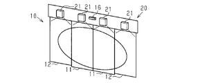
- the perspective view which shows schematic structure of an automatic door system provided with a projection apparatus and an automatic door.
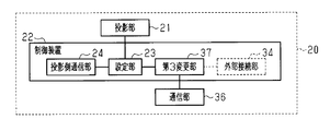
- the block diagram which shows schematic structure in 1st Embodiment of an automatic door system.
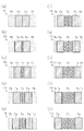
- (A)-(j) The figure which shows the image projected by the projection apparatus of the embodiment.
- (A)-(c) The figure which shows the specific example of the image projected by the projection apparatus of the embodiment.
- the block diagram which shows schematic structure in 2nd Embodiment of a projection apparatus.
- A) The figure which shows the position of the passer-by with respect to the automatic door in the embodiment
- (b) The figure which shows the image of the surface of an automatic door.
- FIG. 1 The figure which shows the image of the surface of the door according to the position of the passerby in 4th Embodiment of an automatic door system.
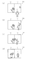
- (A)-(d) The figure which shows the operation
- (A) (b) The figure which shows the passerby and the image of the surface of a door in the automatic door system of the embodiment.
- FIG. 1 The figure which shows an example of the image of the surface of the door in an automatic door system.
- A) (b) The figure which shows the passerby in an automatic door system, and the image projected by a projection apparatus.
- A) (b) The figure which shows the passerby in an automatic door system, and the image projected by a projection apparatus.
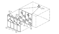
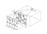
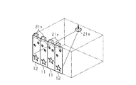
- the figure which shows an example of the projection by a projector The perspective view which shows schematic structure of the modification of an automatic door system.
- the perspective view which shows schematic structure of the modification of an automatic door system The perspective view which shows schematic structure of the modification of an automatic door system.
- the perspective view which shows schematic structure of the modification of an automatic door system The perspective view which shows schematic structure of the modification of an automatic door system.
- the automatic door system includes an automatic door 10 including a door panel (also simply referred to as a door) 11 and a projection device 20 that projects an image on the surface of the door 11.
- the projection device 20 projects an image on almost the entire surface of the door 11.
- the automatic door system is configured so that an image can be projected only on one surface of the door 11, and the projection device 20 is installed only on one surface of the door 11.
- the automatic door system may be configured to project an image on both surfaces of the door 11, and the projection device 20 may be installed on each of the surfaces of the door 11.
- the automatic door 10 includes two movable doors 11, two fixed 12 fixed to a building adjacent to the door 11, and an actuator 18 for moving the door 11. And a door control unit 14 for controlling the drive of the door drive unit 13.
- the fix 12 is a fixed body arranged in parallel with the door 11. When the door 11 moves to a position facing the fix 12, the door opens, and when the door 11 does not face the fix 12, the door closes.
- the door driving unit 13 drives a motor which is an example of the actuator 18 to move the door 11 to a position according to a command from the door control unit 14.
- the door control unit 14 is connected to a door position detection unit 15 that detects the position of the door 11.
- the door position detection unit 15 includes an encoder (not shown) that detects the drive amount of the actuator 18, detects or monitors the position of the door 11 at any time by the encoder, and outputs it to the door control unit 14 as needed.
- the door control unit 14 is connected to a sensor 16 that detects an object such as a person located around the door 11.
- the sensor 16 outputs the detected position of the object together with the detection result of the object located around the door 11 to the door control unit 14.
- the door control unit 14 causes the door drive unit 13 to open the door 11 or close the door 11 based on the detection result output from the sensor 16.
- the door control unit 14 is connected to a door communication unit 17 that outputs the position information of the door 11 detected by the door position detection unit 15 to the outside.
- the door communication unit 17 transmits the position of the door 11 input from the door position detection unit 15 as needed.
- the door communication unit 17 may include a wireless communication circuit that conforms to a short-range wireless communication standard such as Bluetooth (registered trademark).
- the projection device 20 includes a projection unit 21 that projects an image on the surface of the door 11 and a control device 22 that performs control related to the image projected on the surface of the door 11.
- the control device 22 obtains the position of the door 11 detected by the door position detection unit 15 and the setting unit 23 that sets the position of the door 11 detected by the door position detection unit 15 in the projection unit 21 as the image projection position.
- Projection-side communication unit 24 The setting unit 23 sets the position of the image projected on the surface of the door 11 by the projection unit 21 and causes the projection unit 21 to project the image.
- the image projected by the projection unit 21 includes a bright image and a dark image darker than the bright image.
- the setting unit 23 sets the position where the door 11 is opened and the door 11 is no longer present as the position where the dark image is projected.
- the projection-side communication unit 24 acquires the position of the door 11 detected by the door position detection unit 15 from the door control unit 14 of the automatic door 10 and outputs the position to the setting unit 23.
- the projection-side communication unit 24 can include a wireless communication circuit that conforms to a near field communication standard such as Bluetooth (registered trademark).
- the projection unit 21 is a projector that projects an image based on projection data, and is installed on the ceiling of a building where the automatic door 10 is installed.
- the projection unit 21 projects an image onto the door 11 and the fix 12 of the automatic door 10.
- the left side in the figure is the inside of the building and the right side in the figure is the outside of the building, it is assumed that a passerby visually recognizes the image projected on the door 11 when passing from the outside to the inside of the building
- the automatic door system is configured such that a passerby visually recognizes an image projected on the door 11 from the back side of the door 11 from the surface side of the door 11. Note that the projection method of the projector can be arbitrarily changed.
- the image P projected onto the automatic door 10 includes a door image Pa projected onto the surface of the door 11, and is projected onto the surface of the fix 12 where the door 11 is not located. At least one of the image Pb for fixing and the image Pc for the path projected on the area where the door 11 is moved and no longer located is included.
- the image P may be a still image or a moving image.
- the door image Pa and the fix image Pb are bright images that are mainly images of bright colors.
- the passage image Pc is a dark image that is a dark color image. Since the passage image Pc is a dark image, when the passerby of the automatic door 10 passes, the image projected by the projection unit 21 does not feel glare to the passerby.
- the fix image Pb may be a dark image.
- the image P projected from the projection unit 21 onto the automatic door 10 is an image obtained by aligning the position of the door 11 and the position of the door image Pa almost continuously in a temporal space.
- images projected onto the automatic door 10 are ten different images P1 to P10 in ten different scenes in the range in which the door 11 moves. These ten images P are different from each other in the position of the door image Pa in the movement range of the door 11, and the size of the fix image Pb and the size of the passage image Pc are different accordingly.
- FIG. 3 (a) shows an image P1 when the door 11 is closed.
- the image P1 does not have the passage image Pc because the door 11 is closed.
- 3 (b) to 3 (i) show images P2 to P9 when the door 11 is moving. In the images P2 to P9, the size of the fixing image Pb and the size of the passage image Pc are changed by changing the position of the door image Pa.
- FIG. 3J shows an image P10 when the door is fully open. The image P10 does not have the fixing image Pb because the door 11 is fully open.
- the setting unit 23 includes an image processing unit for generating projection data.
- the door image Pa, the fix image Pb, and the passage image Pc are obtained by the projection processing of the projection unit 21 based on the projection data, and the projection data is generated by cutting out from the reference data by the image processing unit.
- the reference data includes data for projecting the door image Pa.
- the reference data includes data for projecting the fix image Pb when the door 11 is closed, and includes data for projecting the passage image Pc when the door 11 is open.
- the reference data is data obtained by combining these three data for one frame, and is prepared separately for the right door 11 and the left door 11.
- the frame expressed by the reference data is set larger than the frame expressed by the projection data.
- the image processing unit included in the setting unit 23 uses the position of the door 11 detected by the door position detection unit 15 and uses the position of the projection data extracted from the reference data so that the door image Pa is positioned on the surface of the door 11. The area is changed according to the position of the door 11.
- the image processing unit included in the setting unit 23 combines the projection data cut out for the right door 11 and the projection data cut out for the left door 11 and transfers the combined projection data to the projection unit 21. To do.
- the image P1 projected when the door 11 is closed is obtained by the image processing unit performing image processing on the reference data according to the result of position detection where the door 11 is located at the closed position.
- the projection data is cut out from the reference data so that the door image Pa is arranged at the closed position of the door 11 in the frame indicated by the projection data.
- the image P10 projected when the door 11 is fully opened is obtained by the image processing unit performing image processing on the reference data according to the result of position detection where the door 11 is located at the open position. .
- the image processing unit cuts out projection data from the reference data.
- the setting unit 23 may hold projection data for projecting the images P1 to P10 for each image, and may select the projection data in accordance with the position of the door 11. With such a configuration, since the image is determined in advance for each position of the door 11, the processing time required for image processing of the reference data can be reduced.
- the position D1 of the closed door 11 is detected by the door position detector 15.
- the automatic door 10 transmits the position information of the door 11 from the door communication unit 17.
- the projection device 20 receives the position information of the door 11 transmitted from the door communication unit 17 via the projection-side communication unit 24 and acquires the position information of the door 11.
- the setting unit 23 of the projection device 20 sets the position D1 of the closed door 11 as the position where the door image Pa is projected based on the acquired position information of the door 11. In other words, the setting unit 23 does not arrange the passage image Pc in the frame indicated by the projection data so that the door image Pa is arranged at the position D1 of the door 11 in the frame indicated by the projection data.
- the projection data is cut out from the reference data.
- the first state image P11 is projected on the projection unit 21 with respect to the position D1 of the door 11.
- the first state image P11 projected on the surface of the door 11 is a still image or a moving image of a person who is calling with both hands to call a customer into a building such as a store.
- the door 11 is in the middle of moving toward the position facing the fix 12, and the door
- the position detector 15 detects the position D2 of the door 11 being moved.
- the setting part 23 of the projection apparatus 20 sets the position D2 of the door 11 in the middle of a movement as a position where the image Pa for doors is projected based on the acquired positional information on the door 11.
- the setting unit 23 arranges the door image Pa at the position D2 of the door 11 in the frame indicated by the projection data, and the fix image Pb and the passage image in the frame indicated by the projection data. Projection data is cut out from the reference data so that Pc is included.
- the setting unit 23 causes the projection unit 21 to project the second state image P12 with respect to the position D2 of the door 11.
- the second state image P12 projected on the surface of the door 11 is a still image or a moving image of a person bowing to a customer entering a building such as a store.
- the setting unit 23 of the projection device 20 sets the position D3 of the fully opened door 11 as the position where the image is projected based on the acquired position information of the door 11.
- the setting unit 23 includes the fix image Pb in the frame indicated by the projection data so that the door image Pa is arranged at the position D3 of the door 11 in the frame indicated by the projection data.
- the projection data is cut out from the reference data so as not to be present.
- the setting unit 23 causes the projection unit 21 to project the third state image P13 with respect to the position D3 of the door 11.
- the third state image P13 projected on the surface of the door 11 is a still image or a moving image of a person bowing, for example, at the position D2 of the door 11.
- the door image Pa is always projected on the door 11 portion of the automatic door 10, so that a passerby of the automatic door 10 approaches the door 11 and passes through the door 11.
- the image can be continuously displayed without being interrupted.
- the passage image Pc formed of a dark image is projected on the passage portion of the automatic door 10, it is possible to suppress a passerby from feeling dazzled.
- the following effects can be obtained. (1) Since the position of the door image Pa to be projected onto the surface of the door 11 is set in accordance with the position of the door 11, the door image Pa is displayed on the surface of the door 11 in conjunction with or following the movement of the door 11. Can continue. In addition, since there is no need to install a display device on the door 11, it is not necessary to provide a cable or the like for supplying power to the display device on the door 11, and it can be installed easily.
- the projection apparatus and automatic door system of this embodiment differ from the first embodiment in that the image projected on the door surface is changed when the state of the object around the door is a predetermined state. ing.
- the image is changed according to the distance between the automatic door and the person who is the object.
- a description will be given focusing on differences from the first embodiment.
- the control device 22 includes a state detection unit 25 that detects the state of an object around the door 11, and an object detected by the state detection unit 25. And a first changing unit 26 that changes an image projected by the projection unit 21 when the state is a predetermined state.
- a sensor 16 provided in the automatic door 10 can detect the position of an object such as a person located around the door 11, the direction in which the object moves, the number of objects, and the like.
- the state detection unit 25 detects the state of the object by acquiring the detection result detected by the sensor 16 of the automatic door 10 from the automatic door 10.
- the first change unit 26 changes the image projected by the projection unit 21 when the state of the object detected by the state detection unit 25 is a position at a predetermined distance from the door 11. That is, since the distance to the door is obtained from the position of the object, the first changing unit 26 changes the reference data according to the distance and changes the image projected by the projection unit 21.
- the reference data used when projecting an image is prepared in advance for each distance between the door 11 and the object.
- the setting unit 23 uses the reference data changed by the first changing unit 26 and performs image processing on the reference data so that the position of the door image Pa matches the position of the door 11.
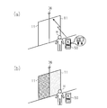
- the state detection unit 25 detects that no object exists because no object such as a person is located around the door 11. 6B, the first changing unit 26 causes the projection unit 21 to project the first state image P21 on the surface of the door 11 according to the detection result of the state detection unit 25. At this time, the first state image P21 is, for example, an image such as “Buy!”.
- the state detection unit 25 has an object such as a person positioned around the door 11 and the distance between the automatic door 10 and the passer-by H is within the first distance L1. It detects that it is in a state. 7B, the first changing unit 26 causes the projection unit 21 to project the second state image P22 on the surface of the door 11 according to the detection result of the state detection unit 25.
- the second state image P22 is an image of, for example, oranges, carrots, cucumbers, potatoes, etc. that are bargain items.
- the state detection unit 25 is configured such that an object such as a person is positioned around the door 11 and the passer-by H approaches the door 11 and the automatic door 10 and the passer-by H Is detected to be within the second distance L2.
- the first changing unit 26 causes the projection unit 21 to project the third state image P ⁇ b> 23 on the surface of the door 11 according to the detection result of the state detection unit 25.
- the third state image P23 is, for example, an image such as strawberry or bread which is a bargain product.
- the state detection unit 25 is configured such that an object such as a person is positioned around the door 11, and the passer-by H approaches the door 11 and the automatic door 10 and the passer-by H Is detected to be within the third distance L3.
- the first changing unit 26 causes the projection unit 21 to project the fourth state image P ⁇ b> 24 on the surface of the door 11 according to the detection result of the state detection unit 25.
- the fourth state image P24 is, for example, an image of apples, bananas, milk, cheese, etc., which are commercially available products.
- the following effects can be achieved.
- (3) When an object such as a passerby is in a predetermined distance, the image on the surface of the door 11 is changed. For this reason, the image according to the predetermined state of objects, such as a passerby, can be projected, and it becomes possible to attract a passer's interest.
- FIGS. 5 and 10 a third embodiment of the projection apparatus and the automatic door system will be described with reference to FIGS. 5 and 10.
- the projection apparatus and automatic door system of this embodiment are different from the second embodiment in that the image projected on the surface of the door is changed in accordance with the direction of movement of a person as an object with respect to the door. .
- the difference from the second embodiment will be mainly described.
- the first changing unit 26 changes the image when the state of the object detected by the state detecting unit 25 is the predetermined moving direction of the object with respect to the door 11. That is, since the moving direction is obtained from the position change of the object, the first changing unit 26 changes the image projected by the projecting unit 21 according to the moving direction.
- the reference data used when projecting an image is prepared in advance for each moving direction of the object.
- the setting unit 23 uses the reference data changed by the first changing unit 26 and performs image processing on the reference data so that the position of the door image Pa matches the position of the door 11.
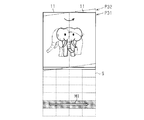
- a sensor area S detected by the sensor 16 is formed around the door 11 of the automatic door 10 as indicated by a broken line in FIG.
- the state detection unit 25 detects the moving direction depending on the order in which the areas obtained by dividing the sensor area S are detected.
- the state detection unit 25 detects that there is no movement. Then, the first change unit 26 causes the projection unit 21 to project the first state image P31 on the surface of the door 11 according to the detection result of the state detection unit 25. At this time, the first state image P31 is an image in which the elephant faces the front.
- the state detection unit 25 moves the object such as a person around the door 11 from the left to the right, and the movement direction of the person is the first movement direction M1. It detects that it is. Then, the first changing unit 26 causes the projection unit 21 to project the second state image P32 on the surface of the door 11 according to the detection result of the state detection unit 25. At this time, the second state image P32 is an image in which the elephant faces left.
- the following effects can be achieved.
- an object such as a passerby is in a predetermined movement direction
- the image on the surface of the door 11 is changed.
- the image according to the predetermined state of objects, such as a passerby can be projected, and it becomes possible to attract a passer's interest.
- FIGS. 5 and 11 a fourth embodiment of the projection apparatus and the automatic door system will be described with reference to FIGS. 5 and 11.
- the projection apparatus and automatic door system of this embodiment differ from the second embodiment in that the image projected on the surface of the door is changed according to the position of a person as an object with respect to the door.
- the difference from the second embodiment will be mainly described.
- the first changing unit 26 changes the image when the state of the object detected by the state detecting unit 25 is a predetermined position with respect to the door 11. That is, the first change unit 26 changes the image projected by the projection unit 21 according to the position of the object.
- Reference data used for image projection is prepared in advance for each position of the object.
- the setting unit 23 uses the reference data changed by the first changing unit 26 and performs image processing on the reference data so that the position of the door image Pa matches the position of the door 11.
- a sensor area S detected by the sensor 16 is formed around the door 11 of the automatic door 10.
- the state detection unit 25 detects the position according to which area of each area obtained by dividing the sensor area S the object is detected.
- the state detection unit 25 detects that an object such as a person is located in any of the left areas near the door 11 in the sensor area S around the door 11. . Then, the first change unit 26 causes the projection unit 21 to project the first state image P41 on the surface of the door 11 according to the detection result of the state detection unit 25. At this time, the first state image P41 is, for example, a mandarin orange image.
- the state detection unit 25 has an object such as a person in any one of the areas on the left side far from the center part from the right side part near the door 11 of the sensor area S around the door 11. Detect if it is located. Then, the first change unit 26 causes the projection unit 21 to project the second state image P42 on the surface of the door 11 according to the detection result of the state detection unit 25. At this time, the second state image P42 is, for example, a strawberry image.
- the state detection unit 25 detects that an object such as a person is located in any one of the areas on the right side away from the door 11 in the sensor area S around the door 11. . Then, the first changing unit 26 causes the projection unit 21 to project the third state image P43 on the surface of the door 11 according to the detection result of the state detection unit 25. At this time, the third state image P43 is, for example, an image of an apple or a banana.
- the image is changed according to the position of an object such as a person around the door 11 with respect to the door 11. For this reason, when the image is changed as described above, the passerby approaches the door 11 and hesitates to enter the store, or when the passerby tries to pass, the image is changed to a different image. Furthermore, goods can be provided via the automatic door 10.
- the following effects can be achieved.
- an object such as a passerby is in a predetermined position
- the image on the surface of the door 11 is changed.
- the image according to the predetermined state of objects, such as a passerby can be projected, and it becomes possible to attract a passer's interest.
- the controller 22 is connected to a photographing unit 27 that photographs an object located around the door 11.
- the photographing unit 27 is, for example, a camera, photographs a passerby located around the door 11, and outputs the photographed image to the generation unit 28.
- the generation unit 28 generates, for example, an image in which different clothes are combined as decoration for the passerby of the photographed image, and outputs the generated image to the setting unit 23 as reference data.
- the setting unit 23 performs image processing on the reference data generated by the generation unit 28.
- the projection unit 21 projects an image indicated by the projection data. An image is generated each time a passerby is positioned around the door 11. Data such as clothes to be decorated are prepared in advance.
- the setting unit 23 projects the image generated by the generation unit 28 according to the position of the door 11.
- the operations of the projection apparatus 20 and the automatic door system configured as described above will be described with reference to FIG.
- the door 11 will be described as being closed.
- the door 11 is opened, and the position of the image is changed according to the position of the door 11.
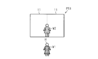
- the shooting unit 27 takes a picture of the passerby H and outputs the shot image data to the generation unit 28.
- the generation unit 28 combines the clothes W1 worn by the passer-by H of the image data captured by the imaging unit 27 so as to replace the clothes W2 sold at the clothes store, and generates combined image data.
- the setting unit 23 causes the projection unit 21 to project the composite image P51 of the image data generated by the generation unit 28 onto the surface of the door 11.
- the composite image P51 is, for example, an image of a passer-by H who wears clothes W2 different from the clothes W1 worn by passers-by H located around the door 11.
- FIGS. 14 and 15 a sixth embodiment of the projection apparatus and the automatic door system will be described with reference to FIGS. 14 and 15.
- the projection apparatus and automatic door system of this embodiment are different from the first embodiment in that an image of a passerby is detected on the door and an image projected on the surface of the door is changed.
- a description will be given focusing on differences from the first embodiment.
- the control device 22 is connected to an operation detection unit 30 that detects a passerby's operation on the door 11.
- the motion detection unit 30 is an optical image sensor, for example, and can detect a touch operation by a passerby on the surface of the door 11.
- the operation detection unit 30 detects the operation of the passerby, for example, by detecting a touch operation performed by the passer on the surface of the door 11.
- the control device 22 further includes a second change unit 31 that changes the image on the surface of the door 11 to the projection unit 21 when the operation detection unit 30 detects a passerby's operation.
- the second changing unit 31 changes the image projected on the surface of the door 11 in accordance with, for example, the passer's motion detected by the motion detection unit 30 and causes the projection unit 21 to project the image.
- Reference data used for image projection is prepared in advance for each passer's action.
- the setting unit 23 performs image processing on the reference data so that the position of the door image Pa is aligned with the position of the door 11 using the reference data changed by the second changing unit 31.
- the control device 22 includes an opening / closing permission unit 32 that permits opening / closing of the door 11 when the operation of the passerby according to the image projected on the surface of the door 11 coincides with a predetermined operation.
- the opening / closing permission unit 32 permits the opening / closing of the door 11 when the operation detecting unit 30 detects the operation of the passerby and coincides with a predetermined operation.
- a first state image P61 including an apple and an anthropomorphic cat that an apple is likely to have on the surfaces of the closed door 11 and the fix 12 of the automatic door 10 is shown. Is projected by the projection unit 21. Passerby H is approaching automatic door 10.
- the first state image P ⁇ b> 61 is projected by the projection unit 21 on the surfaces of the door 11 and the fix 12 of the automatic door 10.
- Passerby H approaches the automatic door 10 and reaches out to the apple projected on the surface of the door 11.
- the motion detection unit 30 detects a touch operation on the apple image of the passer-by H. If the passer-by H operates while performing a touch operation from here, the operation detection unit 30 detects the operation and outputs it to the second changing unit 31.
- the projection unit 21 projects a second state image P62 in which the personified cat has an apple on the surfaces of the door 11 and the fix 12 of the automatic door 10. Yes.
- Passerby H is carrying an anthropomorphized cat by touching the apple projected on the surface of door 11.
- the motion detection unit 30 detects a motion that the passerby H is touching and moving the apple image, and outputs the detected motion to the second change unit 31.
- the second change unit 31 causes the projection unit 21 to project an image in which the position of the apple has been changed in accordance with the movement of the passerby H detected by the movement detection unit 30.
- the control device 22 of the projection device 20 matches the predetermined operation, so that the door 11 can be opened and closed.
- the door 11 is opened with respect to the door control unit 14.
- the image of the surface of the door 11 can be changed by the action of the passerby H on the surface of the door 11. Further, if the door 11 is opened only when a predetermined operation is performed, it can be used as a simple key.
- the following effects can be achieved.
- the image on the surface of the door 11 is changed according to the movement of the passerby H. For this reason, the image of the surface of the door 11 can be changed by the operation of the passerby H.
- FIGS. 16 and 17 a seventh embodiment of the projection apparatus and the automatic door system will be described.
- the projection apparatus and automatic door system of this embodiment are different from the first embodiment in that information projected on the surface of the door is transmitted to a portable terminal carried by a passerby around the door.
- a description will be given focusing on differences from the first embodiment.
- the control device 22 is connected to a transmission unit 33 that transmits information to a portable terminal carried by a passerby around the door 11.
- the transmission unit 33 transmits information projected on the surface of the door 11 to the portable terminal.
- the transmission unit 33 transmits, for example, wireless communication in a UHF (Ultra High Frequency) band.
- the portable terminal may be a terminal having a reception function capable of receiving a radio signal transmitted from the transmission unit 33.
- the control device 22 further includes an external connection unit 34 that obtains information of an image to be projected from the outside, and a data storage unit 35 that stores data of information input from the external connection unit 34.
- the external connection unit 34 is a reader that reads data stored in a storage medium such as a memory card, and outputs the read data to the data storage unit 35.
- the data storage unit 35 stores the data input from the external connection unit 34, causes the setting unit 23 to perform image processing as the reference data, and causes the transmission unit 33 to transmit the stored data.
- the projection device 20 causes the projection unit 21 to project an image included in the data stored in the data storage unit 35 onto the surface of the door 11. Further, the projection device 20 transmits information related to the image projected on the surface of the door 11 to a portable terminal carried by a passerby around the door 11 via the transmission unit 33.
- the first state image P ⁇ b> 71 including, for example, characters “Buy!” Is projected on the surface of the closed door 11 of the automatic door 10 by the projection unit 21. Yes. And when the passerby H approaches the periphery of the door 11, the bargain goods which are projected on the door 11 from the transmission part 33 of the projection apparatus 20 with respect to the portable terminal 50 which the passerby H who approached the door 11 carries. Information is sent.
- information on a purchased product is stored as acquired information in the portable terminal 50 carried by the passer-by H approaching the door 11 and projected as necessary.
- the projection device 20 stops the projection of the first state image P71 that has been projected onto the surface of the door 11 when the information on the product for sale is transmitted. By doing so, the passerby H approaching the door 11 can visually recognize that the information projected on the door 11 has been acquired by the mobile terminal. The passer-by H can enter the store through the opened door 11.
- information projected on the door 11 is transmitted to the portable terminal 50 of the passerby H who has approached the door 11 and the information projected on the door 11 is projected on the door 11.
- further detailed information can be acquired and confirmed together with the information.
- the projection apparatus and the automatic door system of this embodiment are such that when the information held by the portable terminal is received, the image on the surface of the door is changed to an image corresponding to the received information. It is different from the form.
- a description will be given focusing on differences from the first embodiment.
- a communication unit 36 that communicates with a mobile terminal carried by a passerby around the door 11 is connected to the control device 22.
- the communication unit 36 receives information transmitted from the mobile terminal.
- the communication unit 36 receives information transmitted from a mobile terminal by, for example, UHF (Ultra High Frequency) band wireless communication.
- the control device 22 includes a third change unit 37 that changes the image projected by the projection unit 21 to an image corresponding to the received information. Further prepare. That is, the projection device 20 causes the projection unit 21 to project an image included in the data acquired via the communication unit 36 onto the surface of the door 11.
- the projection apparatus 20 acquires the information transmitted from the portable terminal, and projects an image on the surface of the door 11 based on the information transmitted from the portable terminal.
- FIG. 19A no image is projected by the projection unit 21 on the surface of the door 11 where the automatic door 10 is closed.
- image information on the surface of the door 11 is transmitted from the portable terminal 50 carried by the passer-by H approaching the door 11.
- the portable terminal 50 holds color information of an image projected on the surface of the door 11. For example, the left door 11 is blue and the right door 11 is yellow.
- the portable terminal 50 transmits this color information to the automatic door 10.
- the communication unit 36 of the projection device 20 acquires the color information transmitted from the portable terminal 50 by the communication unit 36.
- the third change unit 37 of the control device 22 responds to the acquired color information. Then, the image of the surface of the left door 11 is changed to a blue image, and the image of the surface of the right door 11 is changed to a yellow image, and is projected on the projection unit 21.
- the control device 22 detects an appearance of a passerby around the door 11 and an image on the surface of the door 11 according to the appearance of the passerby detected by the appearance detector 38.
- a fourth changing unit 39 that changes the projection unit 21.
- An imaging unit 27 is connected to the control device 22.
- the photographing unit 27 is, for example, a camera, photographs a passerby located around the door 11, and outputs the photographed image to the appearance detection unit 38.
- the appearance detection unit 38 detects information on the appearance of the passerby from the image input from the photographing unit 27 and outputs, for example, color information to the fourth change unit 39 as the appearance.
- the fourth change unit 39 changes the reference data according to, for example, color information as the appearance of the passerby input from the appearance detection unit 38.
- the setting unit 23 uses the reference data changed by the fourth changing unit 39 and performs image processing on the reference data so that the position of the door image Pa is aligned with the position of the door 11.
- an image is not projected by the projection unit 21 on the surface of the door 11 where the automatic door 10 is closed.
- the photographing unit 27 photographs the passerby H.
- the imaging unit 27 outputs the captured image to the appearance detection unit 38.
- the appearance detection unit 38 detects, for example, blue as color information of the appearance of the passerby H from the captured image, and outputs the detected color to the fourth change unit 39.
- the fourth changing unit 39 changes the surface of the door 11 to a blue image according to the color information input from the appearance detecting unit 38, and the projection unit 21. Project. Accordingly, the color of the appearance of the passer H and the color of the surface of the door 11 are the same color.
- the following effects can be achieved. (12)
- the image on the surface of the door 11 is changed according to the appearance of the passerby H detected by the appearance detection unit 38. For this reason, the third party can recognize the appearance of the passerby H from a distance.
- the tenth embodiment of the projection apparatus and automatic door system will be described below with reference to FIGS.
- the projection device and the automatic door system of this embodiment have a feature that a plurality of different images are projected on the surface of the door while switching, and it is determined that the projected image is selected when the passerby passes the door. This is different from the first embodiment.
- a description will be given focusing on differences from the first embodiment.
- the control device 22 includes a passage detection unit 41 that detects that a passerby has passed through the door 11, and a switching unit that projects a plurality of different images on the surface of the door 11 while projecting the projection unit 21. 42.
- the passage detection unit 41 detects that the passer-by has passed through the door 11 by acquiring the position and moving direction of the passer-by detected by the sensor 16 provided in the automatic door 10.
- the switching unit 42 switches the reference data prepared in advance at regular intervals and causes the projection unit 21 to project different images at regular intervals.
- the control device 22 determines that the image projected when the passer has passed through the door 11 has been selected by the passerby. And a determination unit 43 for determining.
- the door 11 When the passerby enters the area where the door 11 opens while the image switched by the switching unit 42 is projected, the door 11 opens with the image projected at that time. Then, the setting unit 23 projects an image so that the position of the door 11 matches the position of the door image Pa.
- an image PA As shown in FIG. 23, four types of images, an image PA, an image PB, an image PC, and an image PD, are sequentially switched by the switching unit 42 and projected onto the surface of the door 11 of the automatic door 10. .
- the certain time is a time corresponding to the time from when the passerby sees the image and decides to select, and enters the open area where the door 11 opens.
- images are sequentially switched on the surface of the door 11 where the automatic door 10 is closed, and the image PC is projected.
- the passerby H has entered the sensor area S, but has not entered the open area So where the door 11 opens.
- the switching unit 42 stops switching the images and maintains the image PC. Then, when the passer-by H passes the door 11, the determination unit 43 determines that display of the image PC is selected. That is, the determination unit 43 outputs an order to the kitchen or the like, assuming that the setter drawn on the image PC is selected by the passer-by H.
- the automatic door 10 since the image of the surface of the door 11 can be switched and projected and the passer-by H can pass through the door 11, the automatic door 10 can be used as a selection tool. become able to.
- the eleventh embodiment of the projection apparatus and automatic door system will be described below with reference to FIGS.
- the projection apparatus and automatic door system of this embodiment are different from the first embodiment in that the image projected on the surface of the door is changed according to the elapsed time of the closed state of the door.
- a description will be given focusing on differences from the first embodiment.
- the control device 22 responds to the elapsed time detection unit 44 that detects the elapsed time that is the time that has elapsed since the door 11 transitioned to the closed state, and the elapsed time of the closed state of the door 11. And a fifth changing unit 45 that changes an image projected on the surface of the door 11.
- the elapsed time detection unit 44 obtains the detection result of the door position detection unit 15 of the automatic door 10 to grasp that the door 11 is in a closed state, and has elapsed since the door 11 is in a closed state.
- the time is detected and the elapsed time is output to the fifth changing unit 45.
- the fifth changing unit 45 changes the reference data according to the elapsed time of the closed state of the door 11, and further changes the reference data from when the door 11 is in the closed state when the door 11 is in the open state.
- the certain time is a time corresponding to the time from when the passerby sees the image and decides to select, and enters the open area where the door 11 opens.
- a first state image P111 on which no electric wire is drawn is projected on the surface of the door 11. .
- the elapsed time detection unit 44 detects the elapsed time from when the door 11 is closed.
- the second state image P112 in which two birds are stopped on the electric wire is displayed. 11 is projected on the surface.
- the elapsed time detection unit 44 detects the elapsed time in the closed state of the door 11, and the fifth change unit 45 changes the image according to the detected elapsed time.
- a fifth state image P115 different from the closed state of the door 11 is projected onto the surface of the door 11 by the projection unit 21.
- the fifth state image P115 is an image in which a bird that has stopped on the electric wire flies away. Passerby H enters the store through the opened door 11.
- the following effects can be achieved.
- (14) The image on the surface of the door 11 is changed according to the elapsed time after the door 11 is changed to the closed state. For this reason, by looking at the surface of the door 11, the frequency of the door 11 can be confirmed from a distance.
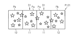
- the setting unit 23 may set the surface of the fix 12 in the projection unit 21 as a position where a bright image is projected. That is, as shown in FIG. 28, the door image Pa projected on the door 11 and the fix image Pb projected on the fix 12 are bright images. Further, the first image P121 that is a continuous image may be projected on the entire door 11 and the fix 12. As shown in FIG. 29, when the door 11 is opened, the passage image Pc is projected as a dark image, and the second image P122, which is a continuous image of the left and right doors 11 and the fix 12, is projected. Good. In this way, since the bright image is projected including not only the door 11 but also the fix 12, the projected area of the bright image can be made larger than that of only the door 11, and visibility can be improved.
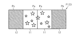
- the setting unit 23 may set the surface of the fix 12 in the projection unit 21 as the position where the dark image is projected. That is, as shown in FIG. 30, the third image P123 is projected in which the door image Pa projected onto the door 11 is a bright image and the fix image Pb projected onto the fix 12 is a dark image. In this way, since a dark image is projected on the fix 12, even if a person located in front of the fix 12 sees the image, glare caused by the projected image can be reduced. Moreover, the bright image of the door 11 can be emphasized more.
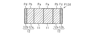
- the setting unit 23 sets the first fix part 12a, which is a part of the surface of the fix 12, to the projection unit 21 as a bright image projection position, and On the surface of the fix 12, the second fix part 12b other than the first fix part 12a may be set in the projection unit 21 as a position where a dark image is projected.
- the projection unit 21 generates a first fix image Pb that is a bright image projected onto the first fix unit 12a and a second fix image Pd that is a dark image projected onto the second fix unit 12b.
- the 4th image P124 which contains is projected. In this way, it is possible to emphasize the first fixed part 12a on which the bright image is projected more prominently than the second fixed part 12b.
- a portion of the surface of the fix 12 that does not face the door 11 when the door 11 is fully opened may be the second fix portion 12b.
- a gap C of a predetermined value for example, 30 mm
- a portion that does not face the door 11 on the surface of the fix 12 when fully opened is a bright image is projected from the position of the door 11 from when the door 11 is fully closed (FIG. 32A) to when it is fully opened (FIG. 32C). Can be set as a range.
- the surface of the fix 12 may include a color part that suppresses reflection of light from the projection part 21.
- the color portion is a film or sheet made of a material that suppresses reflection of light, and is pasted on a portion where a projected image is not desired to be seen by a passerby or the like.
- a color portion is provided in the second fix portion 12b. In this way, without setting the projected image as a dark image, even if the projected image is a bright image, it is possible to prevent a passerby or the like from being visually recognized by the color portion.
- the color portion may be provided in the fix 12 by including a material that suppresses reflection of light in the glass or the like constituting the fix 12 instead of a film or a sheet.
- the setting unit 23 sets the first part 11a, which is a part of the surface of the door 11, to the projection unit 21 as a bright image projection position.
- the second part 11b other than the first part 11a may be set in the projection unit 21 as a position where a dark image is projected.
- the portion of the door bottom vertical stile of the door 11 may be the second portion 11b.
- the projection unit 21 projects a fifth image P125 including a door image Pa that is a bright image projected onto the first part 11a and a second door image Pe projected onto the second part 11b.
- a fix image Pb which is a dark image is projected onto the fix 12.
- the color part may be provided in the door 11 by including a material that suppresses reflection of light in glass or the like constituting the door 11 instead of a film or a sheet.
- you may provide a color part in the part of the door bottom vertical corner of the door 11.
- the setting unit 23 may set a part of the surface of the door 11 in the projection unit 21 as a position where an image is not projected. For example, the image itself is not projected onto the second part 11b in FIG. In this way, since an image is not projected on a portion set as a part of the surface of the door 11, glare can be reduced in a part of the surface of the door 11.
- the setting unit 23 sets the first part 11a, which is a part of the surface of the door 11, to the projection unit 21 as a bright image projection position.
- the second part 11b other than the part 11a may be set in the projection unit 21 as a position where a dark image is projected.
- the 1st part 11a is corresponded in the center part of the two doors 11 connected.
- the projection unit 21 projects a sixth image P126 including a door image Pa that is a bright image projected onto the first part 11a and a second door image Pe projected onto the second part 11b. .
- the setting unit 23 may set a part of the surface of the fix 12 in the projection unit 21 as a position where the image is not projected.
- the first fix portion 12a other than the second fix portion 12b is defined as a position where the second fix portion 12b that is not opposed to the door 11 on the surface of the fix 12 is not projected.
- the door 11 may be the projection range R. In this way, since an image is not projected on a part of the surface of the fix 12 (second fix part 12b), glare can be reduced on a part of the surface of the fix 12.
- the position of the door 11 from when the door 11 is fully closed to when the door 11 is fully open can be set as a range in which an image is projected.
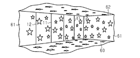
- the projection unit 21 projects the light projecting unit 21 a including the surface of the fix 12 and the surface of the door 11 into the projection target, and at least part of the surface of the fix 12 You may provide with the shielding part 21b comprised so that the projection by the light projection part 21a could be shielded.
- the projection unit 21 since the projection unit 21 includes the shielding unit 21b that shields the projection, the projection unit 21b does not set the projected image as a dark image, but the projected image is a bright image. Dazzling can be reduced by shielding.
- the image processing unit included in the setting unit 23 generates separate common reference data for generating the projection data for the right door 11 and the projection data for the left door 11. Cutting may be performed. That is, the image processing unit included in the setting unit 23 cuts out the right side so that the door image Pa is located on the surface of the right door 11 with respect to one piece of reference data.
- the left-side clipping may be performed so that the door image Pa is positioned on the surface of the left-side door 11.
- the setting unit 23 separately holds the reference data for the door image Pa, the reference data for the fix image Pb, and the reference data for the passage image Pc, and each reference data
- the projection data for the right side may be generated by synthesizing the projection data cut out from.
- the setting unit 23 separately holds the reference data for the door image Pa, the reference data for the fix image Pb, and the reference data for the passage image Pc, and is cut out from each reference data.
- the projection data for the left side may be generated by combining the projection data.
- the relative position is predetermined within one reference data.
- the relative position between characters included in each image is determined in the reference data. Therefore, it is difficult to change the position of the character included in the fix image Pb while fixing the position of the character included in the door image Pa to the door 11.
- the relative character between the character included in the door image Pa and the character included in the fix image Pb is used.
- a specific position is defined between the different reference data. Therefore, while fixing the position of the character included in the door image Pa with respect to the door 11, it is easy to change the position of the character included in the fix image Pb.
- communication is performed between the automatic door 10 and the projection device 20 by short-range wireless communication.
- the wireless door is not limited to short-range wireless communication, and other wireless communication such as a wireless LAN may be used. Further, communication may be performed by wire instead of wireless.
- different reference data may be used when the door 11 moves in the opening direction and when the door 11 moves in the closing direction. In this case, it is necessary to prepare reference data for opening the door 11 and reference data for closing the door 11.
- the area from which the projection data is cut out is for the left door 11 and the right door in one reference data 11 and 11 may be set separately.
- the setting unit 23 may hold the projection data for the left door 11 and the projection data for the right door 11 separately in advance, and set an image in accordance with the movement of each door 11.
- the sensor 16 may be a sensor that can detect the state of an object in a wider range than a normal range used only for opening and closing the door 11. For example, by using an ultrasonic sensor or the like, the passerby H in a range where the image of the surface of the door 11 can be visually recognized can be changed by changing the image of the surface of the door 11. Become.
- image data decorating clothes for passers-by H is synthesized. May be. Further, for example, when introducing a partner, image data in which the partner is arranged next to a passerby may be synthesized.
- the passer-by included in the image data projected onto the surface of the door 11 as the passer-by H moves. H may be moved in the same way.
- opening / closing of the door 11 is permitted when it matches a predetermined operation, but opening / closing of the door 11 is permitted when a passerby performs the same operation projected on the surface of the door 11. May be.
- the opening / closing permission unit 32 is provided and the opening / closing of the door 11 is permitted when the operation of the passer-by H coincides with the predetermined operation.
- An image corresponding to the above may be projected and not used for opening and closing the door 11, and the opening / closing permission unit 32 may be omitted.
- a passerby performs a predetermined action, but an image of a game or the like may be projected on the surface of the door 11 so that the passerby can enjoy the game.
- the motion detection unit 30 is a sensor that detects a touch operation by a passerby.
- the motion detection unit 30 may be a sensor that detects a passer's motion itself.
- information on a bargain product is transmitted from the transmission unit 33 to the mobile terminal 50, but information such as a discount coupon of the product may be transmitted from the transmission unit 33 to the mobile terminal 50. .
- the transmission unit 33 is unidirectional using, for example, UHF band wireless communication, but a wireless LAN, a mobile phone communication network, or the like may be used. In this case, since bidirectional communication is performed, the transmission unit 33 is a communication unit having a transmission / reception function.
- data is read from the storage medium by the external connection unit 34 that is a reader.
- the external connection unit 34 is used as a network connection unit connected to the network, information can be acquired via the network. Good.
- the mobile terminal 50 in the seventh and eighth embodiments may be a mobile phone.
- the portable device 50 is an RFID tag
- the transmission unit 33 is replaced with a reception unit
- the projection apparatus 20 acquires ID information from the RFID tag
- the RFID tag having the acquired ID information Information projected on the surface of the door 11 may be given.
- the passerby holding the RFID tag provides the ID information of the RFID tag to another information terminal, thereby confirming the information given from the projection device 20 on the other information terminal.
- the communication unit 36 is unidirectional using, for example, UHF band wireless communication.
- a wireless LAN, a mobile phone communication network, or the like may be used.
- the mobile terminal 50 may be an RFID tag.
- the color information is used as the appearance of the photographed passerby H.
- the color not only the color but also other information such as the pattern information may be used as the appearance of the passerby H.
- a plurality of images of the door 11 with respect to the appearance of the passerby H may be set and projected onto the door 11. In this way, a third person such as a store clerk can grasp the appearance of the passer-by H without knowing the passer-by H.
- the first change unit 26 detects the surface of the door 11.
- the state may be changed to the eighth image P128 (FIG. 37 (b)).
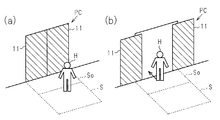
- the other side of the door 11 can be visually recognized, and the passerby H coming from the opposite side can be visually recognized. Further, a part of the image located in front of the passerby at the door 11 may be changed from a projected state to a state where it is not gradually projected.
- the first change unit 26 detects that an object such as a passerby H has approached at least one of the door 11 and the fix 12 by the state detection unit 25.
- the seventh image P127 (FIG. 38 (a)) projected on at least one of the door 11 and the fix 12 may be changed to a ninth image P129 (FIG. 38 (b)) including an image for calling attention.
- the image that prompts attention includes characters and marks such as “caution”.
- the projection unit 21 further projects an image on the floor 60 in contact with at least one of the door 11 and the fix 12, and an object such as a passer-by H is detected by the state detection unit 25.
- the floor 60 may be set at a position where the setting unit 23 projects an image that calls attention, when it is detected that at least one of 11 and the fix 12 is approached. In other words, the setting unit 23 sets the position on the floor 60 where the image for calling attention is projected.
- the first changing unit 26 changes the state (FIG. 39 (a)) where the image for calling attention to the floor 60 is not projected to the state (FIG. 39 (b)) where the image P130 for calling attention to the floor 60 is projected. .
- the image that prompts attention includes characters and marks such as “caution”.
- an object such as a passerby H approaches a door or a fix
- an image that calls attention to the floor 60 is projected.
- the projected image is attracted to the door 11 or the fix 12, it is possible to prevent the passerby H from colliding with the moved door 11 in an attempt to touch the door 11 or the fix 12.
- the passage image Pc including the dark image is projected on the passage portion where the door 11 is opened and the door 11 no longer exists.
- the installation position of the projection unit 21 is changed or the projection method is changed. If the glare can be reduced by doing, an image that is not a dark image may be projected on the passage portion where the door 11 is opened and the door 11 no longer exists.
- the projection unit 21 may project a bright image on the door 11 and the periphery of the door 11 as shown in FIG. That is, a bright image is projected onto the floor 60, the wall 61, and the ceiling 62 in addition to the door 11 and the fix 12. In this way, the bright image is projected on the door 11 and the periphery of the door 11, so that a powerful image can be shown to the passerby.
- an image is projected from one projection unit 21 onto the door 11 and the fix 12, but as shown in FIG. 41, an image is projected from the plurality of projection units 21 onto the door 11 and the fix 12.
- the projected image may be interlocked.
- the projection unit 21 is preferably a short focus type projection apparatus capable of projecting an image at a short distance. In this way, since the interlocked images are projected from the plurality of projection units 21, it is possible to show two or more interlocked information to the passerby.
- an image is projected onto each door 11 and the fix 12 by a plurality of projection units 21.
- a plurality of projection units 21 For example, four second projecting portions 21y corresponding to each of the door 11 and the fix 12 on the outer side are installed on the ceiling.
- the images projected from the second projection unit 21y are desirably connected images.
- one first projection 21x is installed on the ceiling of the door 11 and the fix 12 closer to the inside.
- the setting unit 23 drives the projection units 21x and 21y so that the movement of the image projected on the outer door 11 and the fix 12 and the movement of the image projected on the inner door 11 and the fix 12 are linked. It is desirable to set In addition, you may make the combination of the 1st projection part 21x and the 2nd projection part 21y, and the door 11 and the fix 12 into a reverse combination.
- an image is projected onto each door 11 and the fix 12 by a plurality of projection units 21.
- two second projections 21y are installed on the ceiling of the door 11 and the fix 12 on the outer side. These second projection units 21y project an image for each set of the door 11 and the fix 12.
- the images projected from the second projection unit 21y are desirably connected images.
- one first projection 21x is installed on the ceiling of the door 11 and the fix 12 closer to the inside.
- the setting unit 23 drives the projection units 21x and 21y so that the movement of the image projected on the outer door 11 and the fix 12 and the movement of the image projected on the inner door 11 and the fix 12 are linked. It is desirable to set In addition, you may make the combination of the 1st projection part 21x and the 2nd projection part 21y, and the door 11 and the fix 12 into a reverse combination.
- an image may be projected onto the door 11 and the fix 12 by a plurality of projection units 21.
- the first projection unit 21x that projects an image on the entire door 11 and the fix 12 is installed at a position away from the ceiling door 11 and the fix 12, and the second projection corresponding to each of the door 11 and the fix 12 is provided.
- Four portions 21 y are installed in the immediate vicinity of the ceiling door 11 and the fix 12.
- the images projected from the second projection unit 21y are desirably connected images.
- the setting unit 23 sets the drive of each of the projection units 21x and 21y so that the movement of the image projected on the entire door 11 and the fix 12 and the movement of the image projected on the door 11 and the fix 12, respectively. It is desirable.
- each embodiment may implement combining said each embodiment suitably.
- the projection apparatus 20 which has the structure of each embodiment together. In this way, the image projected on the surface of the door can be changed according to the content that the person using the door 11 wants to project, and various displays can be performed on the person as an object in contact with the automatic door. Can be provided.
- the image is projected on the surface of the door 11 by the projection device 20, but the image is projected not only on the surface corresponding to the outer surface of the door 11 but also on the inner surface of the door by the projection device 20.
- an image can be projected on the inner surface by adopting a door made of laminated glass or the like and having a material capable of projecting an image between the glass and the like.
- the projection device 20 may project an image on a surface including not only the outer surface of the door but also the inner surface.
- the image can be projected on a surface including not only the outer surface but also the inner surface.
- the projection device 20 is installed on the automatic door 10, but the projection device may be installed on a door that is opened and closed manually instead of automatically. In this way, it is possible to easily install a projection device on the door that can continue to display an image on the door in conjunction with or following the movement of the door.
- the projection apparatus and automatic door system can include at least one memory and one or more processors that can access the memory.
- the at least one memory may include computer-executable instructions configured to implement the functions, methods, or configurations described in the above-described embodiments when executed by one or more processors.
- the control device 22 and the door control unit 14 may be realized by a plurality of individual computers each including a memory and a processor, or may be realized by a single computer.
- the present invention includes a computer-readable recording medium (also referred to as a non-transitory medium) that stores computer-executable instructions configured to implement the functions, methods, or configurations described in the above-described embodiments.
- the computer readable medium may be any medium that can be accessed by one or more computer processors, such as RAM, ROM, EEPROM, CD-ROM or other optical disk storage, magnetic disk storage or other magnetic storage device, And any combination thereof.
- SYMBOLS 10 Automatic door, 11 ... Door, 11a ... 1st part, 11b ... 2nd part, 11c ... Door tip vertical stile, 12 ... Fix, 12a ... 1st fix part, 12b ... 2nd fix part, 12c ... Vertical DESCRIPTION OF SYMBOLS 13 ... Door drive part, 14 ... Door control part, 15 ... Door position detection part, 16 ... Sensor, 17 ... Door communication part, 20 ... Projection apparatus, 21 ... Projection part, 21a ... Light projection part, 21b ... Shielding part , 21x ... first projection unit, 21y ... second projection unit, 22 ... control device, 23 ... setting unit, 24 ... projection side communication unit, 25 ...
- state detection unit 26 ... first change unit, 27 ... shooting , 28 ... generating unit, 30 ... motion detecting unit, 31 ... second changing unit, 32 ... opening / closing permission unit, 33 ... transmitting unit, 34 ... external connection unit, 35 ... data storage unit, 36 ... communication unit, 37 ... 3rd change part, 38 ... Appearance detection part, 39 ... 4th change part, 41 ... Pass detection , 42 ... switching unit, 43 ... determination unit, 44 ... elapsed time detection unit, 45 ... fifth change unit, 50 ... mobile terminal, 60 ... floor, 61 ... wall, 62 ... ceiling, C ... gap, H ... passerby , P ... image, R ... projection range.
Landscapes
- Engineering & Computer Science (AREA)
- Physics & Mathematics (AREA)
- General Physics & Mathematics (AREA)
- Computer Hardware Design (AREA)
- Theoretical Computer Science (AREA)
- Multimedia (AREA)
- Signal Processing (AREA)
- Projection Apparatus (AREA)
- Transforming Electric Information Into Light Information (AREA)
- Securing Of Glass Panes Or The Like (AREA)
- Power-Operated Mechanisms For Wings (AREA)
Abstract
投影装置20は、ドア11の面に像を投影する投影部21と、ドア11の位置を検出するドア位置検出部15と、ドア位置検出部15が検出したドア11の位置を像の投影される位置として投影部21に設定する設定部23とを備える。
Description
本発明は、静止画や動画などの像をドアの面に投影する投影装置及び自動ドアシステムに関する。
従来、ドアを自動的に開閉する自動ドアシステムが知られている(例えば、特許文献1参照)。自動ドアシステムは、ドアと、ドアを開閉するためのアクチュエータを駆動するドア駆動部と、ドア駆動部の駆動を制御するコントローラと、ドアに隣接して建物に固定された壁部であるフィックスとを備えている。
特許文献1に記載の自動ドアシステムでは、ドア及びフィックスの少なくとも一方に設置される表示部を備え、ドアの移動に応じた表示を表示部に行わせている。表示部は、電線を介して電力が供給されている。
ところで、上記特許文献1に記載の自動ドアシステムのように、表示部がドアに設置される構成では、表示部用の給電ケーブルや表示部用の信号ケーブルがドアの表面に引き回される。この際に、ドアの開閉がケーブルによって阻害されないように、ドアの移動領域からケーブルを遠ざける必要がある。そのため、こうした自動ドアシステムにおいてはケーブルの引き回しが煩雑である。これに対して、特許文献2に記載のように、ドアから離れた位置に設置される投影装置がドアの表面に像を投影する構成であれば、ドアの表面に引き回される給電ケーブルや信号ケーブルの数自体を少なくすることが可能である。しかしながら、特許文献2に記載のシステムでは、ドアが開放されるときに投影が中断されるため、ドアに対する像の投影がドアの開放に伴って途切れてしまい、ドアに像を投影し続けることができない。
本発明は、こうした実情に鑑みてなされたものであり、その目的は、ドアの移動に連動または追従してドアに像を投影し続けることのできる投影装置及び自動ドアシステムを提供することにある。
本発明の一局面に従う投影装置は、ドアの面に像を投影する投影部と、前記ドアの位置を検出する位置検出部と、前記位置検出部が検出した前記ドアの位置を前記像の投影される位置として前記投影部に設定する設定部とを備えることをその要旨としている。
本発明の一局面に従う自動ドアシステムは、ドアと、前記ドアを開閉するアクチュエータと、前記アクチュエータを駆動するドア駆動部と、上記投影装置とを備えることをその要旨としている。
上記構成によれば、設定部が、ドアの位置に合わせて、ドアの面に投影される像の位置を投影部に設定するため、投影装置は、ドアの移動に連動または追従してドアの面に像を投影し続けることができる。
前記像は、明像と暗像とを含み、前記設定部は、前記位置検出部が検出した位置を用いて前記ドアの移動前の位置を定め、前記移動前の位置を暗像の投影される位置として前記投影部に設定することが好ましい。
上記構成によれば、ドアが移動前の位置から移動したとき、移動前の位置には暗像が投影される。そのため、移動前の位置を通る通行者が、移動前の位置に投影された像を見たとしても、投影された像による眩しさを軽減することができる。
前記設定部は、前記ドアの面の一部である第1部を明像の投影される位置として前記投影部に設定し、且つ、前記ドアの面において前記第1部以外を暗像の投影される位置として前記投影部に設定することが好ましい。
上記構成によれば、ドアの第1部に明像が投影され、ドアの第1部以外に暗像が投影されることで、明像が投影される第1部を第1部以外よりも際立たせて強調することができる。
前記設定部は、前記ドアの面の一部を像が投影されない位置として投影部に設定することが好ましい。
上記構成によれば、ドアの面の一部に設定された部分に像が投影されないので、ドアの面の一部において眩しさを軽減することができる。
上記構成によれば、ドアの面の一部に設定された部分に像が投影されないので、ドアの面の一部において眩しさを軽減することができる。
前記投影部は、前記ドアに並設された固定体であるフィックスの面にさらに像を投影可能に構成され、前記設定部は、前記フィックスの面の一部である第1フィックス部を明像の投影される位置として前記投影部に設定し、且つ、前記フィックスの面において前記第1フィックス部以外を暗像の投影される位置として前記投影部に設定することが好ましい。
上記構成によれば、第1フィックス部に明像が投影され、第1フィックス部以外に暗像が投影されることで、明像が投影される第1フィックス部を第1フィックス部以外よりも際立たせて強調することができる。
前記投影部は、前記ドアに並設された固定体であるフィックスの面にさらに像を投影可能に構成され、前記設定部は、前記フィックスの面の少なくとも一部を明像の投影される位置として前記投影部に設定することが好ましい。
上記構成によれば、ドアだけでなくフィックスも含めて明像が投影されるので、明像の投影面積をドアのみよりも大きくすることができ、視認性を高めることができる。
前記投影部は、前記ドアに並設された固定体であるフィックスの面にさらに像を投影可能に構成され、前記設定部は、前記フィックスの面の少なくとも一部を暗像の投影される位置として前記投影部に設定することが好ましい。
前記投影部は、前記ドアに並設された固定体であるフィックスの面にさらに像を投影可能に構成され、前記設定部は、前記フィックスの面の少なくとも一部を暗像の投影される位置として前記投影部に設定することが好ましい。
上記構成によれば、フィックスに暗像が投影されるので、フィックスの前に人がいたとしても、フィックスの前に位置する人が像を見たとしても、投影された像による眩しさを軽減することができる。
前記設定部は、前記フィックスの面の一部を像の投影されない位置として前記投影部に設定することが好ましい。
上記構成によれば、フィックスの面の一部に像が投影されないので、フィックスの面の一部において眩しさを軽減することができる。
上記構成によれば、フィックスの面の一部に像が投影されないので、フィックスの面の一部において眩しさを軽減することができる。
前記投影部は、前記フィックスの面と前記ドアの面とを投影対象に含める投光部と、前記フィックスの面の少なくとも一部への前記投光部による投影を遮蔽可能に構成された遮蔽部とを備えることが好ましい。
上記構成によれば、投影部に投影を遮蔽する遮蔽部を備えるので、投影される像を暗像に設定することなく、投影される像が明像であったとしても遮蔽部によって遮蔽することで眩しさを軽減することができる。
前記ドアの周辺における物体の状態を検出する状態検出部と、前記状態検出部が検出した前記物体の状態が所定の状態であるときに、前記投影部が投影する像を前記投影部に変更させる第1変更部とをさらに備えることが好ましい。
上記構成によれば、通行者等の物体の状態が所定の状態であるときに、ドアの面における像が変更される。このため、通行者等の物体の所定の状態に応じた像を投影することができ、通行者の興味をひくことができる。
前記第1変更部は、前記ドア及び前記ドアに並設された固定体であるフィックスの少なくとも一方に前記物体が近づいたことを前記状態検出部が検出したときに、前記投影部によって投影される像に、注意を促す像を含めることが好ましい。
上記構成によれば、通行者等の物体がドアやフィックスに近づいたときに、注意を促す像が含まれる像に変更される。このため、投影された像によってドアやフィックスに引き付けられたときに、通行者がドアやフィックスに触ろうとして、移動したドアと衝突することを抑制することができる。
前記投影部は、前記ドア及び前記ドアに並設された固定体であるフィックスの少なくとも一方に接する床にさらに像を投影可能に構成され、前記設定部は、前記投影部に対し、前記注意を促す像の投影される位置に前記床を設定することが好ましい。
上記構成によれば、通行者等の物体がドアやフィックスに近づいたときに、床に注意を促す像が投影される。このため、投影された像によってドアやフィックスに引き付けられたときに、通行者がドアやフィックスに触ろうとして、移動したドアと衝突することを抑制することができる。
前記第1変更部は、前記ドアの面のうち前記物体と対向する領域が、前記設定部において像の投影される位置として設定され、且つ、前記物体が前記ドアに近づいたことを前記状態検出部が検出したときに、前記領域に投影される像の一部を当該一部が投影されないように前記投影部に像を変更させることが好ましい。
上記構成によれば、通行者等の物体がドアに近づいたときに、ドアの面に投影される像によって前方が見え難くなるが、ドアの一部の像が投影されないので、ドアの向こう側が視認でき、ひいては反対側から来る通行者を視認することができる。
前記物体の状態は、前記物体の位置、前記物体の移動する方向、及び前記物体の数の少なくとも1つであることが好ましい。
上記構成によれば、ドアの周辺における通行者等の物体の位置、物体の移動する方向、物体の数の少なくとも1つに基づいて、ドアの面における像が変更される。このため、通行者等の物体の状態である、物体の位置、物体の移動する方向、物体の数に応じた像を投影することができ、通行者の興味を更にひくことができる。
上記構成によれば、ドアの周辺における通行者等の物体の位置、物体の移動する方向、物体の数の少なくとも1つに基づいて、ドアの面における像が変更される。このため、通行者等の物体の状態である、物体の位置、物体の移動する方向、物体の数に応じた像を投影することができ、通行者の興味を更にひくことができる。
前記ドアの周辺に位置する物体を撮影する撮影部と、前記撮影部が撮影した物体に装飾を合成した像を示すデータを生成する生成部とをさらに備え、前記投影部は、投影データが示す像を投影し、前記設定部は、前記生成部が生成したデータを前記投影データに含めることが好ましい。
上記構成によれば、撮影した通行者等の物体に装飾を合成したデータが生成され、生成されたデータが示す像がドアの面に投影される。このため、通行者等の物体自体の投影を変更させることができ、通行者の興味をひくことができる。
前記ドアに対する通行者の動作を検出する動作検出部と、前記動作検出部が通行者の動作を検出したときに、前記投影部が投影する像を前記投影部に変更させる第2変更部とをさらに備えることが好ましい。
上記構成によれば、通行者の動作に応じて、ドアの面における像が変更される。このため、通行者の動作によってドアの面の像を変更することができる。
前記ドアの周辺における通行者が携帯する携帯端末に情報を送信する送信部をさらに備え、前記送信部は、前記投影部が投影している像の情報を、前記携帯端末に送信することが好ましい。
前記ドアの周辺における通行者が携帯する携帯端末に情報を送信する送信部をさらに備え、前記送信部は、前記投影部が投影している像の情報を、前記携帯端末に送信することが好ましい。
上記構成によれば、通行者が携帯している携帯端末が、ドアの面に投影されている情報を取り込むことができる。このため、通行者はドアを通過した後に投影されていた情報を確認することができる。
前記ドアの周辺における通行者が携帯する携帯端末と通信する通信部と、前記携帯端末が保持している情報を前記通信部が受信したときに、受信した情報に応じた像が前記投影部の投影する像に含められるように前記投影部に像を変更させる第3変更部とをさらに備えることが好ましい。
上記構成によれば、通行者が携帯している携帯端末に保持されている情報をドアの面に投影させることができる。このため、通行者が必要とする情報をドアの面に投影させることができる。
前記ドアの周辺に対する通行者の外観を検出する外観検出部と、前記外観検出部が検出した通行者の外観に応じて、前記投影部が投影する像を前記投影部に変更させる第4変更部とをさらに備えることが好ましい。
上記構成によれば、検出された通行者の外観に応じて、ドアの面における像が変更される。このため、第3者が通行者の外観を遠方から認識することができるようになる。
前記ドアを通行者が通過したことを検知する通過検知部と、前記ドアを通行者が通過したときに投影されている像と、当該像以外の像とを前記投影部に切り替えさせる切替部と、通行者が前記ドアを通過したことを前記通過検知部が検知したときに、前記ドアを通行者が通過したときに投影されている像が選択されたと判断し、前記投影部が投影している像から、前記ドアを通行者が通過したときに投影されている像への切り替えを、前記切替部に実行させる判断部とをさらに備えることが好ましい。
前記ドアを通行者が通過したことを検知する通過検知部と、前記ドアを通行者が通過したときに投影されている像と、当該像以外の像とを前記投影部に切り替えさせる切替部と、通行者が前記ドアを通過したことを前記通過検知部が検知したときに、前記ドアを通行者が通過したときに投影されている像が選択されたと判断し、前記投影部が投影している像から、前記ドアを通行者が通過したときに投影されている像への切り替えを、前記切替部に実行させる判断部とをさらに備えることが好ましい。
上記構成によれば、切り替わりながら複数の異なる像がドアの面に投影され、ドアを通行者が通過したときに投影されている像が選択されたと判断される。このため、通行者がドアを通行することで通行者の意思に応じた選択を行うことができるようになる。
前記ドアが閉状態に遷移してから経過した時間である経過時間を検出する経過時間検出部と、前記投影部が投影する像を前記経過時間に応じて変更させる第5変更部とをさらに備えることが好ましい。
上記構成によれば、ドアが閉状態に遷移してからの経過時間に応じて、ドアの面における像が変化される。このため、ドアが開閉した頻度、ひいては、ドアの通行頻度をドアの面に投影された像を見ることで、遠方からでも確認することができる。
前記投影部が投影する像の情報を予め外部から取得する外部接続部をさらに備え、前記設定部は、前記外部接続部が取得した情報に含まれる像が前記投影部の投影する像に含められるように前記投影部の駆動を設定することが好ましい。
上記構成によれば、前記ドアの面に投影するための像の情報を外部から取得することができる。このため、ドアの面に投影させる像に関して変更の自由度を高めることができる。
前記投影部は、前記ドア及び前記ドアの周辺に明像を投影することが好ましい。
上記構成によれば、ドア及びドアの周辺に明像が投影されるので、迫力ある像を通行者等に見せることができる。
上記構成によれば、ドア及びドアの周辺に明像が投影されるので、迫力ある像を通行者等に見せることができる。
前記投影部は、第1の投影部であり、1以上の第2の投影部をさらに備え、前記設定部は、前記第2の投影部が投影する像の動きが、前記第1の投影部が投影する像の動きと連動するように、各前記投影部の駆動を設定することが好ましい。
上記構成によれば、複数の投影部から連動した像が投影されるので、連動した二つ以上の情報を通行者に見せることができる。
本発明の一局面に従う自動ドアシステムは、ドアと、前記ドアを開閉するアクチュエータと、前記アクチュエータを駆動するドア駆動部と、ドアの面に像を投影する投影部と、前記ドアの位置を検出する位置検出部と、前記位置検出部が検出した前記ドアの位置を前記像の投影される位置として前記投影部に設定する設定部と、前記ドアの面に対する通行者の動作を検出する動作検出部と、前記ドアの面に投影された像に応じた前記通行者の動作が予め定められた動作と一致したときに前記ドアの開閉を許可する開閉許可部とを備えることをその要旨としている。
本発明の一局面に従う自動ドアシステムは、ドアと、前記ドアを開閉するアクチュエータと、前記アクチュエータを駆動するドア駆動部と、ドアの面に像を投影する投影部と、前記ドアの位置を検出する位置検出部と、前記位置検出部が検出した前記ドアの位置を前記像の投影される位置として前記投影部に設定する設定部と、前記ドアの面に対する通行者の動作を検出する動作検出部と、前記ドアの面に投影された像に応じた前記通行者の動作が予め定められた動作と一致したときに前記ドアの開閉を許可する開閉許可部とを備えることをその要旨としている。
上記構成によれば、ドアの面における像に応じた通行者の動作が予め定められた動作と一致したときに、ドアの開閉が許可される。このため、ドアの運営者がドアの開閉方法を任意に指定することができる。
前記ドアの面の少なくとも一部は、前記投影部からの光の反射を抑える色部を備えることが好ましい。
上記構成によれば、ドアの面の一部に投影部からの光の反射を抑える色部を備えるので、投影される像を暗像に設定することなく、投影される像が明像であったとしても色部によって通行者等が視認し難くすることができる。
上記構成によれば、ドアの面の一部に投影部からの光の反射を抑える色部を備えるので、投影される像を暗像に設定することなく、投影される像が明像であったとしても色部によって通行者等が視認し難くすることができる。
前記ドアに並設された固定体であるフィックスを備え、前記投影部は、前記フィックスの面にさらに像を投影し、前記フィックスの面の少なくとも一部は、前記投影部からの光の反射を抑える色部を備えることが好ましい。
上記構成によれば、フィックスの面の少なくとも一部に投影部からの光の反射を抑える色部を備えるので、投影される像を暗像に設定することなく、投影される像が明像であったとしても色部によって通行者等が視認し難くすることができる。
本発明によれば、ドアの移動に連動または追従してドアに像を投影し続けることができる投影装置及び自動ドアシステムが得られる。本発明の他の局面及び利点は本発明の技術的思想の例を示している図面と共に以下の記載から明らかとなる。
(第1の実施形態)
以下、図1~図4を参照して、投影装置、及び投影装置と自動ドアとを備える自動ドアシステムの第1の実施形態について説明する。本実施形態の投影装置は、自動ドアに像を投影する位置に設置されている。
以下、図1~図4を参照して、投影装置、及び投影装置と自動ドアとを備える自動ドアシステムの第1の実施形態について説明する。本実施形態の投影装置は、自動ドアに像を投影する位置に設置されている。
図1に示すように、自動ドアシステムは、ドアパネル(単にドアともいう)11を備える自動ドア10と、ドア11の表面に像を投影する投影装置20とを備えている。投影装置20は、ドア11のほぼ全面に像を投影する。自動ドアシステムは、ドア11の有する一方の表面に対してのみ像を投影可能に構成され、ドア11の有する一方の表面に対してのみ投影装置20を設置している。なお、自動ドアシステムは、ドア11の有する両方の表面に対して像を投影可能に構成され、ドア11の有する両方の表面に対してそれぞれ投影装置20を設置してもよい。
図2に示すように、自動ドア10は、移動可能である2枚のドア11と、ドア11に隣接して建物に固定される2枚のフィックス12と、ドア11を移動させるためのアクチュエータ18を駆動するドア駆動部13と、ドア駆動部13の駆動を制御するドア制御部14とを備えている。フィックス12は、ドア11に並設された固定体である。ドア11は、フィックス12に対向する位置に移動すると通路を開き、フィックス12に対向しなくなると通路を閉じる。ドア駆動部13は、アクチュエータ18の一例であるモータを駆動させることで、ドア制御部14の指令に従った位置にドア11を移動させる。
ドア制御部14には、ドア11の位置を検出するドア位置検出部15が接続されている。ドア位置検出部15は、アクチュエータ18の駆動量を検出する図示しないエンコーダを備え、エンコーダによってドア11の位置を随時検出または監視して、ドア制御部14に随時出力する。また、ドア制御部14には、ドア11の周囲に位置する人等の物体を検出するセンサ16が接続されている。センサ16は、ドア11の周囲に位置する物体の検出結果とともに、検出した物体の位置をドア制御部14に出力する。ドア制御部14は、センサ16から出力された検出結果に基づいて、ドア駆動部13によってドア11を開けさせたり、ドア11を閉じさせたりする。さらに、ドア制御部14には、ドア位置検出部15によって検出されたドア11の位置情報を外部に出力するドア通信部17が接続されている。ドア通信部17は、ドア位置検出部15から入力されたドア11の位置を随時送信する。ドア通信部17は、例えばBluetooth(登録商標)等の近距離無線通信規格に適合した無線通信回路を含むことができる。
投影装置20は、ドア11の表面に像を投影する投影部21と、ドア11の表面に投影される像に関わる制御を行う制御装置22とを備えている。制御装置22は、ドア位置検出部15が検出したドア11の位置を像の投影される位置として投影部21に設定する設定部23と、ドア位置検出部15が検出したドア11の位置を得るための投影側通信部24とを備える。設定部23は、投影部21によってドア11の表面に投影される像の位置を設定して、投影部21に投影させる。投影部21によって投影される像には、明像と、明像よりも暗い暗像とが含まれている。設定部23は、ドア11が開いて、ドア11が存在しなくなった位置を暗像が投影される位置として設定する。投影側通信部24は、自動ドア10のドア制御部14からドア位置検出部15が検出したドア11の位置を取得して設定部23に出力する。投影側通信部24は、例えばBluetooth(登録商標)等の近距離無線通信規格に適合した無線通信回路を含むことができる。
図1に示すように、投影部21は、投影データに基づく像を投影するプロジェクタであって、自動ドア10が設置された建物の天井等に設置される。投影部21は、自動ドア10のドア11及びフィックス12に対して像を投影する。ここでは、図中左側を建物の内側、図中右側を建物の外側として、主に通行者が建物の外側から内側へ通過するときにドア11に投影された像を視認することを想定し、ドア11の背面側からドア11に投影された像をドア11の表面側から通行者が視認するように、自動ドアシステムは構成されている。なお、プロジェクタの投影方法は、任意に変更可能である。
図3に示すように、自動ドア10に投影される像Pには、ドア11の表面に投影されるドア用画像Paが含まれ、ドア11の位置していないフィックス12の表面に投影されるフィックス用画像Pb、及びドア11が移動してドア11が位置しなくなった領域に投影される通路用画像Pcの少なくとも一方が含まれる。像Pは、静止画であっても、動画であってもよい。ドア用画像Pa及びフィックス用画像Pbは、主に明色からなる像である明像である。一方、通路用画像Pcは、暗色からなる像である暗像である。通路用画像Pcが暗像であるため、自動ドア10の通行者が通行するときには、投影部21によって投影される画像は、通行者に眩しさを感じない。なお、フィックス12部分に画像が不要な場合は、フィックス用画像Pbを暗像としてもよい。
投影部21から自動ドア10に投影される像Pは、ドア11の位置とドア用画像Paの位置とを時間的な空間においてほぼ連続的に整合させた像である。例えば、自動ドア10に投影される像は、ドア11が移動する範囲における互いに異なる10通りのシーンにおいて、互いに異なる10通りの像P1~P10である。これら10通りの像Pは、ドア11の移動範囲におけるドア用画像Paの位置が互いに異なっており、それに合わせてフィックス用画像Pbの大きさ及び通路用画像Pcの大きさが異なっている。
図3(a)は、ドア11が閉まっているときにおける像P1を示している。像P1は、ドア11が閉まっているため通路用画像Pcを有していない。図3(b)~(i)は、ドア11が移動しているときにおける像P2~P9を示している。像P2~P9は、ドア用画像Paの位置が変化することによって、フィックス用画像Pbの大きさ及び通路用画像Pcの大きさが変化している。図3(j)は、ドアが全開しているときにおける像P10を示している。像P10は、ドア11が全開であるためフィックス用画像Pbを有していない。
設定部23は、投影データを生成するための画像処理部を備えている。ドア用画像Pa、フィックス用画像Pb、および、通路用画像Pcは、投影データに基づく投影部21の投影処理によって得られ、投影データは、画像処理部による基準データからの切り出しによって生成される。
基準データは、ドア用画像Paを投影するためのデータを含む。また、基準データは、ドア11が閉じているときのフィックス用画像Pbを投影するためデータを含み、またドア11が空いているときの通路用画像Pcを投影するためのデータを含む。基準データは、これら3つのデータが1つのフレーム用として合成されたデータであって、右側のドア11用と左側のドア11用とに各別に準備されている。基準データによって表現されるフレームは、投影データによって表現されるフレームよりも大きく設定されている。
設定部23が備える画像処理部は、ドア位置検出部15が検出したドア11の位置を用い、ドア11の表面にドア用画像Paが位置するように、基準データのなかから切り出される投影データの領域をドア11の位置に合わせて変える。設定部23の備える画像処理部は、右側のドア11用として切り出された投影データと、左側のドア11用として切り出された投影データとを合成し、合成された投影データを投影部21に転送する。
例えば、ドア11が閉まっているときに投影される像P1は、ドア11が閉位置に位置する位置検出の結果に応じ、画像処理部が基準データに画像処理を行うことによって得られる。この際に、投影データが示すフレームのなかでドア用画像Paがドア11の閉位置に配置されるように、基準データから投影データを切り出す。また、例えば、ドア11が全開しているときに投影される像P10は、ドア11が開位置に位置する位置検出の結果に応じ、画像処理部が基準データに画像処理を行うことによって得られる。この際に、画像処理部は、基準データから投影データを切り出す。
なお、設定部23は、像P1~P10を投影するための投影データを画像ごとに保持し、ドア11の位置に合わせて投影データを選択してもよい。こうした構成であれば、ドア11の位置毎に予め画像が決まっているので、基準データの画像処理に要する処理時間を削減することができる。
次に、図4を参照して、上記のように構成された投影装置20及び自動ドアシステムの動作について説明する。ここでは、店舗等の建物に設置された自動ドア10における投影装置20及び自動ドアシステムの動作について説明する。
まず、図4(a)に示すように、ドア11は閉じているので、ドア位置検出部15によって閉じているドア11の位置D1が検出されている。自動ドア10は、ドア通信部17からドア11の位置情報を送信する。投影装置20は、ドア通信部17から送信されたドア11の位置情報を、投影側通信部24を介して受信して、ドア11の位置情報を取得する。そして、投影装置20の設定部23は、取得したドア11の位置情報に基づいて、閉じているドア11の位置D1をドア用画像Paの投影される位置として設定する。言い換えれば、設定部23は、投影データが示すフレームのなかでドア用画像Paがドア11の位置D1に配置されるように、かつ投影データが示すフレームのなかに通路用画像Pcが配置されないように、基準データから投影データを切り出す。そして、ドア11の位置D1に対して投影部21に第1状態画像P11を投影させる。このときドア11の表面に投影されている第1状態画像P11は、例えば店舗等の建物の中にお客様を呼び込むために両手を挙げて呼び込んでいる人物の静止画又は動画である。
続いて、図4(b)に示すように、自動ドア10にお客様が近づいてドア11が開けられる範囲にお客様が進入すると、ドア11がフィックス12と対向する位置に向かって移動途中となり、ドア位置検出部15によって移動途中のドア11の位置D2が検出されている。そして、投影装置20の設定部23は、取得したドア11の位置情報に基づいて、移動途中のドア11の位置D2をドア用画像Paの投影される位置として設定する。言い換えれば、設定部23は、投影データが示すフレームのなかでドア用画像Paがドア11の位置D2に配置されるように、かつ投影データが示すフレームのなかにフィックス用画像Pbと通路用画像Pcとが含まれるように、基準データから投影データを切り出す。そして、設定部23は、ドア11の位置D2に対して投影部21に第2状態画像P12を投影させる。このときドア11の表面に投影されている第2状態画像P12は、例えば店舗等の建物の中に入ってくるお客様に対してお辞儀をしている人物の静止画又は動画である。
続いて、図4(c)に示すように、ドア11が全開となっているので、ドア11がフィックス12と対向する位置となり、ドア位置検出部15によって全開のドア11の位置D3が検出されている。そして、投影装置20の設定部23は、取得したドア11の位置情報に基づいて、全開のドア11の位置D3を画像の投影される位置として設定する。言い換えれば、設定部23は、投影データが示すフレームのなかでドア用画像Paがドア11の位置D3に配置されるように、かつ、投影データが示すフレームのなかにフィックス用画像Pbが含まれないように、基準データから投影データを切り出す。そして、設定部23は、ドア11の位置D3に対して投影部21に第3状態画像P13を投影させる。このときドア11の表面に投影されている第3状態画像P13は、例えばドア11の位置D2のときと同様にお辞儀をしている人物の静止画又は動画である。
さて、このような自動ドア10においては、常に自動ドア10のドア11部分にドア用画像Paが投影されているので、自動ドア10の通行者がドア11に接近してドア11を通過するまで画像が途切れることなく画像を表示し続けることができる。また、自動ドア10の通路部分には暗像からなる通路用画像Pcが投影されるので、通行者が眩しさを感じることを抑制することができる。
以上説明したように、本実施形態によれば、以下の効果を奏することができる。
(1)ドア11の位置に合わせてドア11の表面に投影するドア用画像Paの位置が設定されるので、ドア11の移動に連動または追従してドア用画像Paをドア11の表面に表示し続けることができる。また、ドア11に表示装置を設置する必要がないので、表示装置に給電するケーブル等をドア11に配設する必要がなく、容易に設置することができる。
(1)ドア11の位置に合わせてドア11の表面に投影するドア用画像Paの位置が設定されるので、ドア11の移動に連動または追従してドア用画像Paをドア11の表面に表示し続けることができる。また、ドア11に表示装置を設置する必要がないので、表示装置に給電するケーブル等をドア11に配設する必要がなく、容易に設置することができる。
(2)ドア11が開いてドア11が存在しなくなった位置である通路部分を通行者が通過するときに、暗像が投影されるので、投影された像を通行者が見たとしても、眩しさを軽減することができる。また、通路部分に像が投影されていることによる違和感を抑制することができる。
(第2の実施形態)
以下、図5~図9を参照して、投影装置及び自動ドアシステムの第2の実施形態について説明する。この実施形態の投影装置及び自動ドアシステムは、ドアの周辺における物体の状態が所定の状態であるときに、ドアの表面に投影される像が変更される点が上記第1の実施形態と異なっている。特に、本実施形態では、自動ドアと物体である人との距離に合わせて像が変更される。以下、第1の実施形態との相違点を中心に説明する。
以下、図5~図9を参照して、投影装置及び自動ドアシステムの第2の実施形態について説明する。この実施形態の投影装置及び自動ドアシステムは、ドアの周辺における物体の状態が所定の状態であるときに、ドアの表面に投影される像が変更される点が上記第1の実施形態と異なっている。特に、本実施形態では、自動ドアと物体である人との距離に合わせて像が変更される。以下、第1の実施形態との相違点を中心に説明する。
図5に示すように、制御装置22は、設定部23及び投影側通信部24に加えて、ドア11の周辺における物体の状態を検出する状態検出部25と、状態検出部25が検出した物体の状態が所定の状態であるときに、投影部21の投影する像を変更する第1変更部26とを備える。自動ドア10に設けられるセンサ16は、ドア11の周囲に位置する人等の物体の位置、物体の移動する方向、及び物体の数等を検出することが可能である。状態検出部25は、この自動ドア10のセンサ16によって検出された検出結果を自動ドア10から取得することで物体の状態を検出する。第1変更部26は、状態検出部25が検出した物体の状態が、ドア11と所定の距離の位置であるときに、投影部21の投影する像を変更する。すなわち、第1変更部26は、物体の位置からドアとの距離が求められるので、その距離に応じて基準データを変え、投影部21によって投影される像を変更させる。像を投影する際に用いられる基準データは、ドア11と物体との距離毎に予め用意されている。設定部23は、第1変更部26によって変更された基準データを用い、ドア11の位置にドア用画像Paの位置を合わせるように、基準データに対し画像処理を行う。
次に、図6~図9を参照して、上記のように構成された投影装置20及び自動ドアシステムの動作について説明する。ここでは、スーパー等の建物に設置された自動ドア10における投影装置20及び自動ドアシステムの動作について説明する。なお、ドア11は閉まっている状態として説明する。店舗内から人が出てくる場合には、ドア11が開いて、ドア11の位置に応じて像の位置が変更される。
まず、図6(a)に示すように、状態検出部25は、ドア11の周囲に人等の物体が位置していないので、物体が存在しない状態であると検出する。そして、図6(b)に示すように、第1変更部26は、状態検出部25の検出結果に応じて第1状態画像P21をドア11の表面に投影部21によって投影させる。このとき、第1状態画像P21は、例えば「お買得!」等の画像である。
続いて、図7(a)に示すように、状態検出部25は、ドア11の周囲に人等の物体が位置して、自動ドア10と通行者Hとの距離が第1距離L1以内の状態であると検出する。そして、図7(b)に示すように、第1変更部26は、状態検出部25の検出結果に応じて第2状態画像P22をドア11の表面に投影部21によって投影させる。このとき、第2状態画像P22は、例えばお買得な商品であるみかん、にんじん、きゅうり、じゃがいも等の画像である。
続いて、図8(a)に示すように、状態検出部25は、ドア11の周囲に人等の物体が位置して、通行者Hがドア11に近づいて自動ドア10と通行者Hとの距離が第2距離L2以内の状態であると検出する。そして、図8(b)に示すように、第1変更部26は、状態検出部25の検出結果に応じて第3状態画像P23をドア11の表面に投影部21によって投影させる。このとき、第3状態画像P23は、例えばお買得な商品であるいちごやパン等の画像である。
続いて、図9(a)に示すように、状態検出部25は、ドア11の周囲に人等の物体が位置して、通行者Hがドア11に近づいて自動ドア10と通行者Hとの距離が第3距離L3以内の状態であると検出する。そして、図9(b)に示すように、第1変更部26は、状態検出部25の検出結果に応じて第4状態画像P24をドア11の表面に投影部21によって投影させる。このとき、第4状態画像P24は、例えばお買得な商品であるりんご、バナナ、牛乳、チーズ等の画像である。
さて、このような自動ドア10においては、ドア11の周囲における通行者H等の物体のドア11との距離に応じて画像が変更されるので、上記のように画像を変更した場合には、通行者はお店に近づきながらお買得な商品の情報を、自動ドア10を介して提供されることができる。
以上説明したように、本実施形態によれば、第1の実施形態の(1)及び(2)の効果に加え、以下の効果を奏することができる。
(3)通行者等の物体の状態が所定の距離の状態であるときに、ドア11の表面における像が変更される。このため、通行者等の物体の所定の状態に応じた像を投影することができ、通行者の興味をひくことができるようになる。
(3)通行者等の物体の状態が所定の距離の状態であるときに、ドア11の表面における像が変更される。このため、通行者等の物体の所定の状態に応じた像を投影することができ、通行者の興味をひくことができるようになる。
(第3の実施形態)
以下、図5及び図10を参照して、投影装置及び自動ドアシステムの第3の実施形態について説明する。この実施形態の投影装置及び自動ドアシステムは、ドアに対する物体としての人の移動する方向に合わせて、ドアの表面に投影される像が変更される点が上記第2の実施形態と異なっている。以下、第2の実施形態との相違点を中心に説明する。
以下、図5及び図10を参照して、投影装置及び自動ドアシステムの第3の実施形態について説明する。この実施形態の投影装置及び自動ドアシステムは、ドアに対する物体としての人の移動する方向に合わせて、ドアの表面に投影される像が変更される点が上記第2の実施形態と異なっている。以下、第2の実施形態との相違点を中心に説明する。
図5に示すように、第1変更部26は、状態検出部25が検出した物体の状態が、ドア11に対する物体の移動方向が所定方向であるときに像を変更する。すなわち、第1変更部26は、物体の位置変化から移動方向が求められるので、その移動方向に応じて投影部21によって投影される像を変更させる。像を投影する際に用いられる基準データは、物体の移動方向毎に予め用意されている。設定部23は、第1変更部26によって変更された基準データを用い、ドア11の位置にドア用画像Paの位置を合わせるように、基準データに対し画像処理を行う。
図10の破線に示すように、自動ドア10のドア11の周囲には、センサ16によって検出されるセンサエリアSが形成されている。状態検出部25は、このセンサエリアS内を分割した各エリアがどの順番で検出したかによって移動方向を検出する。
次に、図10を参照して、上記のように構成された投影装置20及び自動ドアシステムの動作について説明する。ここでは、博物館等の建物に設置された自動ドア10における投影装置20及び自動ドアシステムの動作について説明する。なお、ドア11は閉まっている状態として説明する。建物内から人が出てくる場合には、ドア11が開いて、ドア11の位置に応じて像の位置が変更される。
まず、図10の実線に示すように、状態検出部25は、ドア11の周囲の人等の物体が移動していないときには、移動がない状態であると検出する。そして、第1変更部26は、状態検出部25の検出結果に応じて第1状態画像P31をドア11の表面に投影部21によって投影させる。このとき、第1状態画像P31は、ゾウが正面を向いた画像である。
続いて、図10の二点鎖線に示すように、状態検出部25は、ドア11の周囲の人等の物体が左から右へ移動して、人の移動方向が第1移動方向M1の状態であると検出する。そして、第1変更部26は、状態検出部25の検出結果に応じて第2状態画像P32をドア11の表面に投影部21によって投影させる。このとき、第2状態画像P32は、ゾウが左を向いた画像である。
さて、このような自動ドア10においては、ドア11の周囲における人等の物体の移動方向に応じて像が変更されるので、上記のように像を変更した場合には、通行者は投影されたゾウの見たい部分を、自分が移動することで投影させることができる。
以上説明したように、本実施形態によれば、第1の実施形態の(1)及び(2)の効果に加え、以下の効果を奏することができる。
(4)通行者等の物体の状態が所定の移動方向の状態であるときに、ドア11の表面における像が変更される。このため、通行者等の物体の所定の状態に応じた像を投影することができ、通行者の興味をひくことができるようになる。
(4)通行者等の物体の状態が所定の移動方向の状態であるときに、ドア11の表面における像が変更される。このため、通行者等の物体の所定の状態に応じた像を投影することができ、通行者の興味をひくことができるようになる。
(第4の実施形態)
以下、図5及び図11を参照して、投影装置及び自動ドアシステムの第4の実施形態について説明する。この実施形態の投影装置及び自動ドアシステムは、ドアに対する物体としての人の位置に合わせて、ドアの表面に投影される像が変更される点が上記第2の実施形態と異なっている。以下、第2の実施形態との相違点を中心に説明する。
以下、図5及び図11を参照して、投影装置及び自動ドアシステムの第4の実施形態について説明する。この実施形態の投影装置及び自動ドアシステムは、ドアに対する物体としての人の位置に合わせて、ドアの表面に投影される像が変更される点が上記第2の実施形態と異なっている。以下、第2の実施形態との相違点を中心に説明する。
図5に示すように、制御装置22は、第1変更部26は、状態検出部25が検出した物体の状態が、ドア11に対して所定の位置であるときに像を変更する。すなわち、第1変更部26は、物体の位置に応じて投影部21によって投影される像を変更させる。像の投影に用いられる基準データは、物体の位置毎に予め用意されている。設定部23は、第1変更部26によって変更された基準データを用い、ドア11の位置にドア用画像Paの位置を合わせるように、基準データに対し画像処理を行う。
図11の破線に示すように、自動ドア10のドア11の周囲には、センサ16によって検出されるセンサエリアSが形成されている。状態検出部25は、このセンサエリアS内を分割した各エリアのどのエリアで物体を検出したかによって位置を検出する。
次に、図11を参照して、上記のように構成された投影装置20及び自動ドアシステムの動作について説明する。ここでは、スーパー等の建物に設置された自動ドア10における投影装置20及び自動ドアシステムの動作について説明する。なお、ドア11は閉まっている状態として説明する。店舗内から人が出てくる場合には、ドア11が開いて、ドア11の位置に応じて像の位置が変更される。
図11(a)に示すように、状態検出部25は、ドア11の周囲のセンサエリアSのドア11に近くて左側の各エリアのいずれかに人等の物体が位置していると検出する。そして、第1変更部26は、状態検出部25の検出結果に応じて第1状態画像P41をドア11の表面に投影部21によって投影させる。このとき、第1状態画像P41は、例えばみかんの画像である。
図11(b)に示すように、状態検出部25は、ドア11の周囲のセンサエリアSのドア11に近い右側部分から中央部分から遠い左側部分の各エリアのいずれかに人等の物体が位置していると検出する。そして、第1変更部26は、状態検出部25の検出結果に応じて第2状態画像P42をドア11の表面に投影部21によって投影させる。このとき、第2状態画像P42は、例えばいちごの画像である。
図11(c)に示すように、状態検出部25は、ドア11の周囲のセンサエリアSのドア11に遠くて右側の各エリアのいずれかに人等の物体が位置していると検出する。そして、第1変更部26は、状態検出部25の検出結果に応じて第3状態画像P43をドア11の表面に投影部21によって投影させる。このとき、第3状態画像P43は、例えばりんごやバナナの画像である。
さて、このような自動ドア10においては、ドア11の周囲における人等の物体のドア11に対する位置に応じて画像が変更される。このため、上記のように画像を変更した場合には、通行者はドア11に近づいて入店を躊躇していたり、通り過ぎようとしたりしたときに異なる画像に変更されて、通行者の移動によってさらに商品を、自動ドア10を介して提供することができる。
以上説明したように、本実施形態によれば、第1の実施形態の(1)及び(2)の効果に加え、以下の効果を奏することができる。
(5)通行者等の物体の状態が所定の位置の状態であるときに、ドア11の表面における像が変更される。このため、通行者等の物体の所定の状態に応じた像を投影することができ、通行者の興味をひくことができるようになる。
(5)通行者等の物体の状態が所定の位置の状態であるときに、ドア11の表面における像が変更される。このため、通行者等の物体の所定の状態に応じた像を投影することができ、通行者の興味をひくことができるようになる。
(第5の実施形態)
以下、図12及び図13を参照して、投影装置及び自動ドアシステムの第5の実施形態について説明する。この実施形態の投影装置及び自動ドアシステムは、ドアの周辺に位置する物体としての人を撮影して、撮影した人に装飾を合成した像をドアの表面に投影する点が上記第1の実施形態と異なっている。以下、第1の実施形態との相違点を中心に説明する。
以下、図12及び図13を参照して、投影装置及び自動ドアシステムの第5の実施形態について説明する。この実施形態の投影装置及び自動ドアシステムは、ドアの周辺に位置する物体としての人を撮影して、撮影した人に装飾を合成した像をドアの表面に投影する点が上記第1の実施形態と異なっている。以下、第1の実施形態との相違点を中心に説明する。
図12に示すように、制御装置22には、ドア11の周辺に位置する物体を撮影する撮影部27が接続されている。撮影部27は、例えばカメラであって、ドア11の周囲に位置する通行者を撮影して、撮影した画像を生成部28に出力する。生成部28は、撮影した画像の通行者に装飾として、例えば異なる服を合成した画像を生成して、設定部23に基準データとして出力する。設定部23は、生成部28が生成した基準データに画像処理を行う。投影部21は、投影データが示す像を投影する。画像は、ドア11の周囲に通行者が位置する度に生成される。装飾される服等のデータは予め用意されている。設定部23は、生成部28によって生成された像を、ドア11の位置に合わせて投影させる。
次に、図13を参照して、上記のように構成された投影装置20及び自動ドアシステムの動作について説明する。ここでは、服屋等の建物に設置された自動ドア10における投影装置20及び自動ドアシステムの動作について説明する。なお、ドア11は閉まっている状態として説明する。店舗内から人が出てくる場合には、ドア11が開いて、ドア11の位置に応じて像の位置が変更される。
まず、図13に示すように、撮影部27は、ドア11の周囲に通行者Hが位置すると、通行者Hを撮影して、撮影した画像データを生成部28に出力する。そして、生成部28は、撮影部27が撮影した画像データの通行者Hが着ている服W1を服店で販売している服W2に替わるように合成して、合成した画像データを生成して設定部23に出力する。設定部23は、生成部28によって生成された画像データの合成画像P51をドア11の表面に投影部21によって投影させる。このとき、合成画像P51は、例えばドア11の周囲に位置する通行者Hが着ている服W1と異なる服W2を着た通行者Hの画像である。
さて、このような自動ドア10においては、ドア11の周囲における通行者Hを装飾した画像が投影されるので、通行者Hは服店の商品が着せられた自分を見ることができ、服店で販売している商品を自分に着せながら把握することができる。よって、通行者Hは、購買意欲がかきたてられる。
以上説明したように、本実施形態によれば、第1の実施形態の(1)及び(2)の効果に加え、以下の効果を奏することができる。
(6)撮影した通行者Hに装飾を合成したデータが生成されて、生成されたデータの像がドア11の表面に投影される。このため、通行者H自体の投影を変更させることができ、通行者Hの興味をひくことができるようになる。
(6)撮影した通行者Hに装飾を合成したデータが生成されて、生成されたデータの像がドア11の表面に投影される。このため、通行者H自体の投影を変更させることができ、通行者Hの興味をひくことができるようになる。
(第6の実施形態)
以下、図14及び図15を参照して、投影装置及び自動ドアシステムの第6の実施形態について説明する。この実施形態の投影装置及び自動ドアシステムは、ドアに対する通行者の動作を検出して、ドアの表面に投影される像が変更される点が上記第1の実施形態と異なっている。以下、第1の実施形態との相違点を中心に説明する。
以下、図14及び図15を参照して、投影装置及び自動ドアシステムの第6の実施形態について説明する。この実施形態の投影装置及び自動ドアシステムは、ドアに対する通行者の動作を検出して、ドアの表面に投影される像が変更される点が上記第1の実施形態と異なっている。以下、第1の実施形態との相違点を中心に説明する。
図14に示すように、制御装置22には、ドア11に対する通行者の動作を検出する動作検出部30が接続されている。動作検出部30は、例えば光学式イメージセンサであって、ドア11の表面に対する通行者によるタッチ操作を検出可能である。動作検出部30は、例えば通行者がドア11の表面に対して行ったタッチ操作を検出することで、通行者の動作を検出する。また、制御装置22は、動作検出部30が通行者の動作を検出したときに、ドア11の表面における像を投影部21に変更させる第2変更部31をさらに備える。第2変更部31は、例えば動作検出部30が検出した通行者の動作に合わせて、ドア11の表面に投影される像を変更して、投影部21によって投影させる。像の投影に用いられる基準データは、通行者の動作毎に予め用意されている。設定部23は、第2変更部31によって変更された基準データを用い、ドア11の位置にドア用画像Paの位置を合わせるように、基準データに対し画像処理を行う。また、制御装置22は、ドア11の表面に投影された像に応じた通行者の動作が予め定められた動作と一致したときにドア11の開閉を許可する開閉許可部32とを備える。開閉許可部32は、動作検出部30によって通行者の動作を検出して予め定められた動作と一致したときにドア11の開閉を許可する。
次に、図15を参照して、上記のように構成された投影装置20及び自動ドアシステムの動作について説明する。ここでは、おもちゃ屋等の建物に設置された自動ドア10における投影装置20及び自動ドアシステムの動作について説明する。
まず、図15(a)に示すように、自動ドア10の閉じているドア11及びフィックス12の表面には、りんごと、りんごが欲しそうな擬人化した猫とを含んだ第1状態画像P61が投影部21によって投影されている。通行者Hは、自動ドア10に近づいてきている。
続いて、図15(b)に示すように、自動ドア10のドア11及びフィックス12の表面には、第1状態画像P61が投影部21によって投影されている。通行者Hは、自動ドア10に近づいて、ドア11の表面に投影されたりんごに手を伸ばしている。このとき、動作検出部30は、通行者Hのりんごの画像へのタッチ操作を検出している。動作検出部30は、ここから通行者Hがタッチ操作しながら動作したらその動作を検出して第2変更部31に出力する。
続いて、図15(c)に示すように、自動ドア10のドア11及びフィックス12の表面には、擬人化した猫がりんごを持っている第2状態画像P62が投影部21によって投影されている。通行者Hは、ドア11の表面に投影されたりんごに触れて擬人化した猫まで運んでいる。動作検出部30は、通行者Hがりんごの画像に触れて動かしている動作を検出して、第2変更部31に出力する。第2変更部31は、動作検出部30が検出した通行者Hの動作に合わせて、りんごの位置を変更した画像を投影部21に投影させる。投影装置20の制御装置22は、自動ドア10に投影された画像のりんごが擬人化した猫に渡されると、予め定められた動作と一致するのでドア11の開閉を許可して、自動ドア10のドア制御部14に対してドア11を開かせる。
続いて、図15(d)に示すように、自動ドア10のドア11が開いて、ドア11の表面には、擬人化した猫がりんごをもらって喜んでいる第3状態画像P63が投影部21によって投影されている。通行者Hは、開いたドア11を通過している。
さて、このような自動ドア10においては、ドア11の表面に対する通行者Hの動作によってドア11の表面の画像を変更することができる。また、予め決まった動作を行ったときにのみドア11を開けるようにすれば、簡易の鍵として使用することができる。
以上説明したように、本実施形態によれば、第1の実施形態の(1)及び(2)の効果に加え、以下の効果を奏することができる。
(7)通行者Hの動作に応じて、ドア11の表面における像が変更される。このため、通行者Hの動作によってドア11の表面の像を変更することができる。
(7)通行者Hの動作に応じて、ドア11の表面における像が変更される。このため、通行者Hの動作によってドア11の表面の像を変更することができる。
(8)ドア11の表面における像に応じた通行者Hの動作が予め定められた動作と一致したときに、ドア11の開閉が許可される。このため、ドア11の運営者がドア11の開閉方法を任意に指定することができる。また、簡易の鍵として使用することができるようになる。
(第7の実施形態)
以下、図16及び図17を参照して、投影装置及び自動ドアシステムの第7の実施形態について説明する。この実施形態の投影装置及び自動ドアシステムは、ドアの表面に投影している情報を、ドアの周辺における通行者が携帯する携帯端末に送信する点が上記第1の実施形態と異なっている。以下、第1の実施形態との相違点を中心に説明する。
以下、図16及び図17を参照して、投影装置及び自動ドアシステムの第7の実施形態について説明する。この実施形態の投影装置及び自動ドアシステムは、ドアの表面に投影している情報を、ドアの周辺における通行者が携帯する携帯端末に送信する点が上記第1の実施形態と異なっている。以下、第1の実施形態との相違点を中心に説明する。
図16に示すように、制御装置22には、ドア11の周辺における通行者が携帯する携帯端末に情報を送信する送信部33が接続されている。送信部33は、ドア11の表面に投影している情報を携帯端末に送信する。送信部33は、例えばUHF(Ultra High Frequency)帯の無線通信によって送信する。携帯端末は、送信部33から送信された無線信号を受信できる受信機能を有する端末であればよい。また、制御装置22は、投影する像の情報を外部から取得する外部接続部34と、外部接続部34から入力された情報のデータを記憶するデータ記憶部35とをさらに備える。外部接続部34は、例えばメモリーカード等の記憶メディアに記憶されたデータを読み出すリーダであって、読み出したデータをデータ記憶部35に出力する。データ記憶部35は、外部接続部34から入力されたデータを記憶し、記憶したデータを基準データとして設定部23に画像処理させたり、送信部33によって送信させたりする。投影装置20は、データ記憶部35に記憶したデータに含まれる画像を投影部21によってドア11の表面に投影させる。また、投影装置20は、このドア11の表面に投影された画像に関連した情報を、送信部33を介してドア11の周辺における通行者が携帯する携帯端末に送信する。
次に、図17を参照して、上記のように構成された投影装置20及び自動ドアシステムの動作について説明する。ここでは、スーパー等の建物に設置された自動ドア10における投影装置20及び自動ドアシステムの動作について説明する。
まず、図17(a)に示すように、自動ドア10の閉じているドア11の表面には、例えば「お買得!」との文字を含む第1状態画像P71が投影部21によって投影されている。そして、ドア11の周辺に通行者Hが近づくと、ドア11に近づいた通行者Hが携帯する携帯端末50に対して投影装置20の送信部33からドア11に投影しているお買得な商品の情報が送信される。
続いて、図17(b)に示すように、ドア11に近づいた通行者Hが携帯する携帯端末50には、取得情報としてお買得な商品の情報が記憶され、必要に応じて投影される。投影装置20は、お買得な商品の情報を送信すると、ドア11の表面に投影していた第1状態画像P71の投影を止める。こうすることで、ドア11に近づいた通行者Hには、ドア11に投影されていた情報が携帯端末に取得されたことが視認されるようにできる。通行者Hは、開いたドア11を通過して入店することができる。
さて、このような自動ドア10においては、ドア11に投影した情報をドア11に近づいた通行者Hの携帯端末50に、ドア11に投影した情報が送信されるので、ドア11に投影された情報とともに、例えばさらに詳しい情報等を取得して確認することができるようになる。
以上説明したように、本実施形態によれば、第1の実施形態の(1)及び(2)の効果に加え、以下の効果を奏することができる。
(9)通行者Hが携帯している携帯端末50にドア11の表面に投影されている情報を取り込むことができる。このため、通行者Hはドア11を通過した後に投影されていた情報を確認することができるようになる。
(9)通行者Hが携帯している携帯端末50にドア11の表面に投影されている情報を取り込むことができる。このため、通行者Hはドア11を通過した後に投影されていた情報を確認することができるようになる。
(10)外部接続部34を介して外部から投影する像の情報を取得することができる。このため、ドア11の運営者又は所有者がドア11の表面に投影させる像を自由に変更することができる。
(第8の実施形態)
以下、図18及び図19を参照して、投影装置及び自動ドアシステムの第8の実施形態について説明する。この実施形態の投影装置及び自動ドアシステムは、携帯端末が保持している情報を受信したときに、ドアの表面における像が受信した情報に応じた像に変更される点が上記第1の実施形態と異なっている。以下、第1の実施形態との相違点を中心に説明する。
以下、図18及び図19を参照して、投影装置及び自動ドアシステムの第8の実施形態について説明する。この実施形態の投影装置及び自動ドアシステムは、携帯端末が保持している情報を受信したときに、ドアの表面における像が受信した情報に応じた像に変更される点が上記第1の実施形態と異なっている。以下、第1の実施形態との相違点を中心に説明する。
図18に示すように、制御装置22には、ドア11の周辺における通行者が携帯する携帯端末と通信する通信部36が接続されている。通信部36は、携帯端末から送信された情報を受信する。通信部36は、携帯端末から例えばUHF(Ultra High Frequency)帯の無線通信によって送信された情報を受信する。また、制御装置22は、携帯端末が保持している情報を通信部36が受信したときに、投影部21が投影する像を、受信した情報に応じた像に変更する第3変更部37をさらに備える。すなわち、投影装置20は、通信部36を介して取得したデータに含まれる画像を投影部21によってドア11の表面に投影させる。また、投影装置20は、携帯端末から送信された情報を取得して、携帯端末から送信された情報に基づいてドア11の表面に画像を投影させる。
次に、図19を参照して、上記のように構成された投影装置20及び自動ドアシステムの動作について説明する。ここでは、店舗等の建物に設置された自動ドア10における投影装置20及び自動ドアシステムの動作について説明する。
まず、図19(a)に示すように、自動ドア10の閉じているドア11の表面には、画像が投影部21によって投影されていない。そして、ドア11の周辺に通行者Hが近づくと、ドア11に近づいた通行者Hが携帯する携帯端末50からドア11の表面における画像の情報が送信される。携帯端末50には、ドア11の表面に投影する像の色情報が保持されている。色情報は、例えば左側のドア11が青色、右側のドア11が黄色とする。携帯端末50は、この色情報を自動ドア10に送信する。投影装置20の通信部36は、携帯端末50から送信された色情報を通信部36によって取得する。
続いて、図19(b)に示すように、携帯端末50から送信された色情報を通信部36を介して取得すると、制御装置22の第3変更部37は、取得した色情報に応じて、左側のドア11の表面の画像を青色の画像に、右側のドア11の表面の画像を黄色の画像に変更して、投影部21に投影させる。
さて、このような自動ドア10においては、通行者Hが携帯する携帯端末50が保持する色情報に応じた画像をドア11の表面に投影させるので、通行者Hの好みの色にドア11を変更することができる。
以上説明したように、本実施形態によれば、第1の実施形態の(1)及び(2)の効果に加え、以下の効果を奏することができる。
(11)通行者Hが携帯している携帯端末50に保持されている情報をドア11の表面に投影させることができる。このため、通行者Hが必要とする情報をドア11の表面に投影させることができる。
(11)通行者Hが携帯している携帯端末50に保持されている情報をドア11の表面に投影させることができる。このため、通行者Hが必要とする情報をドア11の表面に投影させることができる。
(第9の実施形態)
以下、図20及び図21を参照して、投影装置及び自動ドアシステムの第9の実施形態について説明する。この実施形態の投影装置及び自動ドアシステムは、ドアの周辺に対する通行者の外観を検出して、検出した通行者の外観に応じてドアの表面に投影される像が変更される点が上記第1の実施形態と異なっている。以下、第1の実施形態との相違点を中心に説明する。
以下、図20及び図21を参照して、投影装置及び自動ドアシステムの第9の実施形態について説明する。この実施形態の投影装置及び自動ドアシステムは、ドアの周辺に対する通行者の外観を検出して、検出した通行者の外観に応じてドアの表面に投影される像が変更される点が上記第1の実施形態と異なっている。以下、第1の実施形態との相違点を中心に説明する。
図20に示すように、制御装置22は、ドア11の周辺に対する通行者の外観を検出する外観検出部38と、外観検出部38が検出した通行者の外観に応じてドア11の表面における像を投影部21に変更させる第4変更部39とをさらに備える。制御装置22には、撮影部27が接続されている。撮影部27は、例えばカメラであって、ドア11の周辺に位置する通行者を撮影して、撮影した画像を外観検出部38に出力する。外観検出部38は、撮影部27から入力された画像から通行者の外観の情報を検出して、外観として例えば色情報を第4変更部39に出力する。第4変更部39は、外観検出部38から入力された通行者の外観として例えば色情報に応じて基準データを変更する。設定部23は、第4変更部39によって変更された基準データを用い、ドア11の位置にドア用画像Paの位置を合わせるように、基準データに対し画像処理を行う。
次に、図21を参照して、上記のように構成された投影装置20及び自動ドアシステムの動作について説明する。ここでは、店舗等の建物に設置された自動ドア10における投影装置20及び自動ドアシステムの動作について説明する。
まず、図21(a)に示すように、自動ドア10の閉じているドア11の表面には、像が投影部21によって投影されていない。そして、ドア11の周辺に通行者Hが近づいてセンサエリアSに進入すると、撮影部27は通行者Hを撮影する。撮影部27は、撮影した画像を外観検出部38に出力する。外観検出部38は、撮影した画像から通行者Hの外観の色情報として例えば青色を検出して、第4変更部39に出力する。
続いて、図21(b)に示すように、第4変更部39は、外観検出部38から入力された色情報に応じてドア11の表面を青色の画像に変更して、投影部21に投影させる。よって、通行者Hの外観の色と、ドア11の表面の色とが同じ色となる。
さて、このような自動ドア10においては、通行者Hの外観の色情報に応じた画像をドア11の表面に投影させるので、通行者Hの外観を店内にいる店員等が知ることができる。
以上説明したように、本実施形態によれば、第1の実施形態の(1)及び(2)の効果に加え、以下の効果を奏することができる。
(12)外観検出部38によって検出された通行者Hの外観に応じて、ドア11の表面における像が変更される。このため、第3者が通行者Hの外観を遠方から認識することができるようになる。
(12)外観検出部38によって検出された通行者Hの外観に応じて、ドア11の表面における像が変更される。このため、第3者が通行者Hの外観を遠方から認識することができるようになる。
(第10の実施形態)
以下、図22~図24を参照して、投影装置及び自動ドアシステムの第10の実施形態について説明する。この実施形態の投影装置及び自動ドアシステムは、ドアの表面に複数の異なる像を切り替えながら投影させて、ドアを通行者が通過したときに投影されている像が選択されたと判断される点が上記第1の実施形態と異なっている。以下、第1の実施形態との相違点を中心に説明する。
以下、図22~図24を参照して、投影装置及び自動ドアシステムの第10の実施形態について説明する。この実施形態の投影装置及び自動ドアシステムは、ドアの表面に複数の異なる像を切り替えながら投影させて、ドアを通行者が通過したときに投影されている像が選択されたと判断される点が上記第1の実施形態と異なっている。以下、第1の実施形態との相違点を中心に説明する。
図22に示すように、制御装置22は、ドア11を通行者が通過したことを検知する通過検知部41と、ドア11の表面に複数の異なる像を切り替えながら投影部21に投影させる切替部42とを備える。通過検知部41は、自動ドア10に設けられるセンサ16によって検出される通行者の位置及び移動方向を取得することで、通行者がドア11を通過したことを検知する。切替部42は、予め用意された基準データを一定間隔毎に切り替えて、異なる像を一定間隔毎に投影部21に投影させる。また、制御装置22は、通行者がドア11を通過したことを通過検知部41が検知したときに、通行者がドア11を通過したときに投影されている像が、通行者によって選択されたと判断する判断部43とをさらに備える。
切替部42によって切り替えられた画像が投影されているときに、ドア11が開くエリアに通行者が進入すると、そのときの画像を投影した状態でドア11は開く。そして、ドア11の位置とドア用画像Paの位置とが合うように、設定部23は像を投影する。
次に、図23及び図24を参照して、上記のように構成された投影装置20及び自動ドアシステムの動作について説明する。ここでは、飲食店等の建物に設置された自動ドア10における投影装置20及び自動ドアシステムの動作について説明する。
図23に示すように、自動ドア10のドア11の表面には、画像PA、画像PB、画像PC、画像PDの4種類の画像が順に切替部42によって一定時間毎に切り替えられて投影される。なお、4種類の画像には、異なる定食がそれぞれ描かれているとする。ここでの一定時間は、通行者が画像を見て、選択することを決定して、ドア11が開くオープンエリアに進入するまでの時間に相当する時間である。
まず、図24(a)に示すように、自動ドア10の閉じているドア11の表面には、画像が順に切り替えられて、画像PCが投影された状態である。通行者Hは、センサエリアSに進入しているが、ドア11が開くオープンエリアSoには進入していない。
続いて、図24(b)に示すように、通行者HがオープンエリアSoに進入すると、切替部42は画像の切り替えを停止して、画像PCを維持する。そして、通行者Hがドア11を通過すると、判断部43は、画像PCの表示が選択されたと判断する。すなわち、判断部43は、画像PCに描かれた定食を通行者Hが選択したとして、厨房等に注文として出力する。
さて、このような自動ドア10においては、ドア11の表面の画像を切り替えて投影して、通行者Hがドア11を通過することで選択できるので、自動ドア10を選択ツールとして使用することができるようになる。
以上説明したように、本実施形態によれば、第1の実施形態の(1)及び(2)の効果に加え、以下の効果を奏することができる。
(13)切り替わりながら複数の異なる像がドア11の表面に投影され、ドア11を通行者Hが通過したときに投影されている像が選択されたと判断される。このため、通行者Hがドア11を通行することで通行者Hの意思に応じた選択を行うことができるようになる。
(13)切り替わりながら複数の異なる像がドア11の表面に投影され、ドア11を通行者Hが通過したときに投影されている像が選択されたと判断される。このため、通行者Hがドア11を通行することで通行者Hの意思に応じた選択を行うことができるようになる。
(第11の実施形態)
以下、図25~図27を参照して、投影装置及び自動ドアシステムの第11の実施形態について説明する。この実施形態の投影装置及び自動ドアシステムは、ドアの閉状態の経過時間に応じてドアの表面に投影される像が変更される点が上記第1の実施形態と異なっている。以下、第1の実施形態との相違点を中心に説明する。
以下、図25~図27を参照して、投影装置及び自動ドアシステムの第11の実施形態について説明する。この実施形態の投影装置及び自動ドアシステムは、ドアの閉状態の経過時間に応じてドアの表面に投影される像が変更される点が上記第1の実施形態と異なっている。以下、第1の実施形態との相違点を中心に説明する。
図25に示すように、制御装置22は、ドア11が閉状態に遷移してから経過した時間である経過時間を検出する経過時間検出部44と、ドア11の閉状態の経過時間に応じてドア11の表面に投影させる像を変更させる第5変更部45とをさらに備える。経過時間検出部44は、自動ドア10のドア位置検出部15の検出結果を取得することで、ドア11が閉状態となったことを把握して、ドア11が閉状態となってからの経過時間を検出して、その経過時間を第5変更部45に出力する。第5変更部45は、ドア11の閉状態の経過時間に応じて基準データを変更させるとともに、ドア11が開状態となったときに、ドア11が閉状態であるときから基準データをさらに変更させる。
次に、図26及び図27を参照して、上記のように構成された投影装置20及び自動ドアシステムの動作について説明する。ここでは、店舗等の建物に設置された自動ドア10における投影装置20及び自動ドアシステムの動作について説明する。
図26に示すように、自動ドア10のドア11の表面には、画像PA、画像PB、画像PC、画像PDの4種類の画像が順に切替部42によって一定時間毎に切り替えられて投影される。なお、4種類の画像には、異なる定食がそれぞれ描かれているとする。ここでの一定時間は、通行者が画像を見て、選択することを決定して、ドア11が開くオープンエリアに進入するまでの時間に相当する時間である。
まず、図26(a)に示すように、自動ドア10のドア11が閉じられたばかりのときには、何も止まっていない電線が描かれた第1状態画像P111がドア11の表面に投影されている。経過時間検出部44は、ドア11が閉状態となったときから経過時間を検出している。
続いて、図26(b)に示すように、自動ドア10のドア11が閉じられて数分、例えば2分経過したときには、電線に2羽の鳥が止まっている第2状態画像P112がドア11の表面に投影されている。ここでは、ドア11が閉状態となってから1分経過する毎に鳥が1羽増えることとする。すなわち、経過時間検出部44がドア11の閉状態の経過時間を検出して、第5変更部45が検出された経過時間に応じて画像を変更する。
続いて、図26(c)に示すように、自動ドア10のドア11が閉じられて例えば5分経過したときには、電線に5羽の鳥が止まっている第3状態画像P113がドア11の表面に投影されている。
続いて、図26(d)に示すように、自動ドア10のドア11が閉じられて例えば9分経過したときには、電線に9羽の鳥が止まっている第4状態画像P114がドア11の表面に投影されている。
そして、図27に示すように、ドア11が開かれると、ドア11が閉状態のときとは異なる第5状態画像P115が投影部21によってドア11の表面に投影される。第5状態画像P115は、電線に止まっていた鳥が飛び立った画像である。通行者Hは、開いたドア11を通過して店内に進入する。
さて、このような自動ドア10においては、ドア11の表面に、ドア11の閉状態の経過時間に応じた画像を投影するので、ドア11を見ることでドア11の通行頻度を確認することができる。
以上説明したように、本実施形態によれば、第1の実施形態の(1)及び(2)の効果に加え、以下の効果を奏することができる。
(14)ドア11が閉状態に遷移してからの経過時間に応じて、ドア11の表面における像が変化される。このため、ドア11の表面を見ることでドア11の通行頻度を遠方から確認することができる。
(14)ドア11が閉状態に遷移してからの経過時間に応じて、ドア11の表面における像が変化される。このため、ドア11の表面を見ることでドア11の通行頻度を遠方から確認することができる。
(他の実施形態)
なお、上記各実施形態は、これを適宜変更した以下の形態にて実施することもできる。
・上記各実施形態において、設定部23がフィックス12の面を明像の投影される位置として投影部21に設定してもよい。すなわち、図28に示すように、ドア11に投影されるドア用画像Pa及びフィックス12に投影されるフィックス用画像Pbを明像とする。また、ドア11及びフィックス12の全体に連続した像である第1画像P121を投影してもよい。そして、図29に示すように、ドア11が開いたときには、通路用画像Pcを暗像として投影し、左右それぞれのドア11及びフィックス12を連続した像である第2画像P122を投影してもよい。このようにすれば、ドア11だけでなくフィックス12も含めて明像が投影されるので、明像の投影面積をドア11のみよりも大きくすることができ、視認性を高めることができる。
なお、上記各実施形態は、これを適宜変更した以下の形態にて実施することもできる。
・上記各実施形態において、設定部23がフィックス12の面を明像の投影される位置として投影部21に設定してもよい。すなわち、図28に示すように、ドア11に投影されるドア用画像Pa及びフィックス12に投影されるフィックス用画像Pbを明像とする。また、ドア11及びフィックス12の全体に連続した像である第1画像P121を投影してもよい。そして、図29に示すように、ドア11が開いたときには、通路用画像Pcを暗像として投影し、左右それぞれのドア11及びフィックス12を連続した像である第2画像P122を投影してもよい。このようにすれば、ドア11だけでなくフィックス12も含めて明像が投影されるので、明像の投影面積をドア11のみよりも大きくすることができ、視認性を高めることができる。
・上記各実施形態において、設定部23がフィックス12の面を暗像の投影される位置として投影部21に設定してもよい。すなわち、図30に示すように、ドア11に投影されるドア用画像Paを明像として、フィックス12に投影されるフィックス用画像Pbを暗像とした第3画像P123を投影する。このようにすれば、フィックス12に暗像が投影されるので、フィックス12の前に位置する人が像を見たとしても、投影された像による眩しさを軽減することができる。またドア11の明像をより強調することができる。
・上記各実施形態において、図31に示すように、設定部23がフィックス12の面の一部である第1フィックス部12aを明像の投影される位置として投影部21に設定し、且つ、フィックス12の面において第1フィックス部12a以外の第2フィックス部12bを暗像の投影される位置として投影部21に設定してもよい。このとき、投影部21は、第1フィックス部12aに投影される明像である第1フィックス用画像Pbと、第2フィックス部12bに投影される暗像である第2フィックス用画像Pdとを含む第4画像P124を投影する。このようにすれば、明像が投影される第1フィックス部12aを第2フィックス部12bよりも際立たせて強調することができる。
・また、図32(a)~(c)に示すように、ドア11を全開したときにフィックス12の面においてドア11と対向しない部分を上記の第2フィックス部12bとしてもよい。図32(c)に示すように、自動ドアにおいては全開時にドア11の戸先縦かまち11cとフィックス12の方立12cとの間に所定値(例えば30mm)以上の隙間Cを設けているため、全開時にフィックス12の面においてドア11と対向しない部分が存在する。このように第2フィックス部12bを設定することで、ドア11の全閉時(図32(a))から全開時(図32(c))までのドア11の存在位置を明像の投射される範囲として設定することができる。
・上記各実施形態において、フィックス12の面の少なくとも一部は、投影部21からの光の反射を抑える色部を備えてもよい。この色部は、光の反射を抑える材質からなるフィルムやシートであって、投影された像を通行者等に視認されたくない部分に貼り付けられる。例えば、上記の第2フィックス部12bに色部を設ける。このようにすれば、投影される像を暗像に設定することなく、投影される像が明像であったとしても色部によって通行者等が視認できないようにすることができる。なお、色部は、フィルムやシートでなく、フィックス12を構成するガラス等に光の反射を抑える材質が含まれることでフィックス12に設けられていてもよい。
・上記各実施形態において、図33に示すように、設定部23がドア11の面の一部である第1部11aを明像の投影される位置として投影部21に設定し、ドア11の面において第1部11a以外の第2部11bを暗像の投影される位置として投影部21に設定してもよい。例えば、ドア11の戸尻縦かまちの部分を第2部11bとしてもよい。このとき、投影部21は、第1部11aに投影される明像であるドア用画像Paと、第2部11bに投影される第2ドア用画像Peとを含む第5画像P125が投影する。また、フィックス12に暗像であるフィックス用画像Pbを投影する。このようにすれば、ドア11の第1部11aに明像が投影され、ドア11の第2部11bに暗像が投影されることで、明像が投影される第1部11aを第2部11bよりも際立たせて強調することができる。
・上記各実施形態において、ドア11の面の少なくとも一部は、投影部21からの光の反射を抑える色部を備えてもよい。この色部は、光の反射を抑える材質からなるフィルムやシートであって、投影された像を通行者等に視認されたくないドア11の部分に貼り付けられる。このようにすれば、ドア11の面の一部に投影された像を視認できない色部を備えるので、投影される像を暗像に設定することなく、投影される像が明像であったとしても色部によって通行者等が視認できないようにできる。なお、色部は、フィルムやシートでなく、ドア11を構成するガラス等に光の反射を抑える材質が含まれることでドア11に設けられていてもよい。例えば、ドア11の戸尻縦かまちの部分に色部を設けてもよい。
・上記各実施形態において、設定部23がドア11の面の一部を像の投影されない位置として投影部21に設定してもよい。例えば、図33の第2部11bに像自体を投影しないようにする。このようにすれば、ドア11の面の一部に設定された部分に像が投影されないので、ドア11の面の一部において眩しさを軽減することができる。
・また、図34に示すように、設定部23がドア11の面の一部である第1部11aを明像の投影される位置として投影部21に設定し、ドア11の面において第1部11a以外の第2部11bを暗像の投影される位置として投影部21に設定してもよい。第1部11aは連接する2枚のドア11の中央部分に相当する。このとき、投影部21は、第1部11aに投影される明像であるドア用画像Paと、第2部11bに投影される第2ドア用画像Peとを含む第6画像P126を投影する。このようにすれば、ドア11の第1部11aに明像が投影され、ドア11の第2部11bに暗像が投影されることで、明像が投影される第1部11aを第2部11bよりも際立たせて強調することができる。
・上記各実施形態において、設定部23がフィックス12の面の一部を像の投影されない位置として投影部21に設定してもよい。例えば、図35に示すように、ドア11を全開時にフィックス12の面においてドア11と対向しない部分である第2フィックス部12bを投影されない位置として、第2フィックス部12b以外の第1フィックス部12aとドア11とを投射範囲Rとしてもよい。このようにすれば、フィックス12の面の一部(第2フィックス部12b)に像が投影されないので、フィックス12の面の一部において眩しさを軽減することができる。また、ドア11の全閉時から全開時までのドア11の存在位置を像の投射される範囲として設定することができる。
・上記各実施形態において、図36に示すように、投影部21が、フィックス12の面とドア11の面とを投影対象に含める投光部21aと、フィックス12の面の少なくとも一部への投光部21aによる投影を遮蔽可能に構成された遮蔽部21bとを備えてもよい。このようにすれば、投影部21に投影を遮蔽する遮蔽部21bを備えるので、投影される像を暗像に設定することなく、投影される像が明像であったとしても遮蔽部21bによって遮蔽することで眩しさを軽減することができる。
・上記各実施形態において、設定部23の備える画像処理部は、右側のドア11用の投影データと、左側のドア11用の投影データを生成することに際し、共通する1つの基準データに別々の切り出しを行ってもよい。すなわち、設定部23が備える画像処理部は、1つの基準データに対し、右側のドア11の表面にドア用画像Paが位置するように、右側用の切り出しを行い、また、同じ基準データに対し、左側のドア11の表面にドア用画像Paが位置するように、左側用の切り出しを行ってもよい。こうした構成であれば、右側のドア11に投影される像と、左側のドア11に投影される像とが、そもそも1つの基準データから得られるものであるため、右側のドア11に投影される像と、左側のドア11に投影される像との対称性や統一感を高めることが可能である。
・上記各実施形態において、設定部23は、ドア用画像Pa用の基準データと、フィックス用画像Pb用の基準データと、通路用画像Pc用の基準データとを別々に保持し、各基準データから切り出された投影データを合成することによって、右側用の投影データを生成してもよい。同様に、設定部23は、ドア用画像Pa用の基準データと、フィックス用画像Pb用の基準データと、通路用画像Pc用の基準データとを別々に保持し、各基準データから切り出された投影データを合成することによって、左側用の投影データを生成してもよい。
上記変形例に記載したように、1つの基準データからこれら3つの画像用の投影データを切り出す構成においては、例えば、ドア用画像Paに含まれるキャラクターと、フィックス用画像Pbに含まれるキャラクターとの相対的な位置が、1つの基準データ内において予め定められている。言い換えれば、1つの基準データからこれら3つの画像用の投影データを切り出す構成においては、各画像に含まれるキャラクター間の相対位置などが、基準データ内において定められている。それゆえに、ドア用画像Paに含まれるキャラクターの位置をドア11に対し固定する一方で、フィックス用画像Pbに含まれるキャラクターの位置を変えることが難しい。
一方で、上述したように、3つの画像用の投影データが別々の基準データから切り出される構成においては、例えば、ドア用画像Paに含まれるキャラクターと、フィックス用画像Pbに含まれるキャラクターとの相対的な位置が、別々の基準データ間において定められている。それゆえに、ドア用画像Paに含まれるキャラクターの位置をドア11に対し固定する一方で、フィックス用画像Pbに含まれるキャラクターの位置を変えることが容易でもある。
・上記各実施形態では、自動ドア10と投影装置20との間で近距離無線通信によって通信したが、近距離無線通信に限らず、無線LAN等の他の無線通信を用いてもよい。また、無線ではなく、有線によって通信してもよい。
・上記第1の実施形態において、ドア11が開く方向へ移動するときと、ドア11が閉じる方向へ移動するときとで異なる基準データを用いてもよい。この場合には、ドア11が開くとき用の基準データとドア11が閉じるとき用の基準データとを用意する必要がある。
・上記第1の実施形態において、2枚のドア11が異なるタイミングで開閉することがある自動ドア10では、投影データの切り出される領域が、1つの基準データにおいて左側のドア11用と右側のドア11用とで別々に設定されてもよい。また、設定部23が左側のドア11用の投影データと、右側のドア11用の投影データとを予め別々に保持し、各ドア11の移動に合わせて画像を設定してもよい。
・上記第2の実施形態において、センサ16は、ドア11の開閉のみに用いる通常の範囲よりも広い範囲において物体の状態を検出可能なセンサを使用してもよい。例えば、超音波センサ等を用いて、ドア11の表面の画像を視認することができる範囲の通行者Hに対してドア11の表面の画像を変更することで興味を持たせることができるようになる。
・上記第5の実施形態では、通行者Hに服を装飾した画像データを合成したが、服に限らず、通行者Hに靴、帽子、鞄や、髪型等を装飾した画像データを合成してもよい。また、例えば、パートナーを紹介するところでは、通行者の隣にパートナーを配置した画像データを合成してもよい。
・上記第5の実施形態において、通行者Hがドア11の表面に沿って通過するようなときには、通行者Hの移動に伴って、ドア11の表面に投影される画像データに含まれる通行者Hを同じように移動させてもよい。
・上記第6の実施形態では、予め定められた動作と一致したらドア11の開閉を許可したが、ドア11の表面に投影された動作を通行者が同じように行ったらドア11の開閉を許可してもよい。
・上記第6の実施形態では、開閉許可部32を備えて、通行者Hの動作が予め定められた動作と一致したときにドア11の開閉を許可したが、通行者Hのドア11に対する動作に応じた画像を投影させ、ドア11の開閉には用いないようにして、開閉許可部32を省略してもよい。
・上記第6の実施形態では、予め定められた動作を通行者が行うようにしたが、ドア11の表面にゲーム等の画像を投影して、通行者がゲームを楽しめるようにしてもよい。
・上記第6の実施形態では、動作検出部30が通行者によるタッチ操作を検出するセンサとしたが、動作検出部30が通行者の動作そのものを検出するセンサとしてもよい。
・上記第6の実施形態では、動作検出部30が通行者によるタッチ操作を検出するセンサとしたが、動作検出部30が通行者の動作そのものを検出するセンサとしてもよい。
・上記第7の実施形態では、例えばお買得な商品の情報を送信部33から携帯端末50に送信したが、商品の割引クーポン等の情報を送信部33から携帯端末50に送信してもよい。
・上記第7の実施形態では、送信部33が例えばUHF帯の無線通信を用いて単方向としたが、無線LANや携帯電話通信網等を利用してもよい。この場合は、双方向の通信となるので、送信部33を、送受信機能を有する通信部とする。
・上記第7の実施形態では、記憶メディアからリーダである外部接続部34によってデータを読み出したが、外部接続部34をネットワークに接続されるネットワーク接続部としてネットワークを介して情報を取得してもよい。
・上記第7,8の実施形態における携帯端末50は、携帯電話であってもよい。
・上記第7の実施形態において、携帯端末50をRFIDタグとして、送信部33を受信部に替えて、RFIDタグからID情報を投影装置20が取得して、取得したID情報を有するRFIDタグにドア11の表面に投影していた情報を付与したこととしてもよい。この場合、RFIDタグを保持する通行者は、別の情報端末にRFIDタグのID情報を提供することで、投影装置20から付与された情報を別の情報端末上で確認する。
・上記第7の実施形態において、携帯端末50をRFIDタグとして、送信部33を受信部に替えて、RFIDタグからID情報を投影装置20が取得して、取得したID情報を有するRFIDタグにドア11の表面に投影していた情報を付与したこととしてもよい。この場合、RFIDタグを保持する通行者は、別の情報端末にRFIDタグのID情報を提供することで、投影装置20から付与された情報を別の情報端末上で確認する。
・上記第8の実施形態では、通信部36が例えばUHF帯の無線通信を用いて単方向としたが、無線LANや携帯電話通信網等を利用してもよい。
・上記第8の実施形態において、携帯端末50をRFIDタグとしてもよい。
・上記第8の実施形態において、携帯端末50をRFIDタグとしてもよい。
・上記第9の実施形態では、撮影された通行者Hの外観として色情報を使用したが、色だけでなく、通行者Hの外観として柄情報等の他の情報を使用してもよい。また、通行者Hの外観に対するドア11の画像を複数設定しておいてドア11に投影させるようにしてもよい。このようにすれば、通行者Hにはわからずに、通行者Hの外観を店員等の第3者が把握することができるようになる。
・上記各実施形態において、図37に示すように、第1変更部26が、通行者H等の物体がドア11に近づいたことを状態検出部25が検出したときに、ドア11の面のうち通行者H等の物体と対向する領域に投影される像の一部を投影している状態の第7画像P127(図37(a))から投影される像の一部を投影していない状態の第8画像P128(図37(b))に変更させてもよい。このようにすれば、通行者H等の物体がドア11に近づいたときに、ドア11の面に投影される像によって前方が見え難くなるが、ドア11の一部の像が投影されないので、ドア11の向こう側が視認でき、ひいては反対側から来る通行者Hを視認することができる。また、ドア11における通行者の前方に位置する一部の像を、投影している状態から徐々に投影していない状態に変更してもよい。
・上記各実施形態において、図38に示すように、第1変更部26が、状態検出部25によって通行者H等の物体がドア11及びフィックス12の少なくとも一方に近づいたことを検出したときに、ドア11及びフィックス12の少なくとも一方に投影される第7画像P127(図38(a))を、注意を促す像を含む第9画像P129(図38(b))に変更させてもよい。注意を促す像は、「注意」等の文字やマークを含む。このようにすれば、通行者H等の物体がドア11やフィックス12に近づいたときに、ドア11の面に注意を促す像に変更される。このため、投影された像によってドア11やフィックス12に引き付けられたときに、通行者Hがドア11やフィックス12に触ろうとして、移動したドア11と衝突することを抑制することができる。
・上記各実施形態において、図39に示すように、投影部21がドア11及びフィックス12の少なくとも一方に接する床60にさらに像を投影し、状態検出部25によって通行者H等の物体がドア11及びフィックス12の少なくとも一方に近づいたことを検出したときに、設定部23が注意を促す像の投影される位置に床60を設定してもよい。すなわち、設定部23が注意を促す像の投影される位置を床60に設定する。第1変更部26は、床60に注意を促す像を投影していない状態(図39(a))から床60に注意を促す像P130を投影した状態(図39(b))に変更する。注意を促す像は、「注意」等の文字やマークを含む。このようにすれば、通行者H等の物体がドアやフィックスに近づいたときに、床60に注意を促す像が投影される。このため、投影された像によってドア11やフィックス12に引き付けられたときに、通行者Hがドア11やフィックス12に触ろうとして、移動したドア11と衝突することを抑制することができる。
・上記各実施形態では、ドア11が開いてドア11が存在しなくなった通路部分に暗像からなる通路用画像Pcを投影したが、投影部21の設置位置を変更したり、投影方法を変更したりすることにより、眩しさを軽減することができれば、ドア11が開いてドア11が存在しなくなった通路部分に暗像ではない画像を投影してもよい。
・上記各実施形態において、図40に示すように、投影部21がドア11及びドア11の周辺に明像を投影してもよい。すなわち、ドア11及びフィックス12に加えて、床60、壁61、及び天井62に明像を投影する。このようにすれば、ドア11及びドア11の周辺に明像が投影されるので、迫力ある像を通行者等に見せることができる。
・上記各実施形態では、1個の投影部21からドア11及びフィックス12に像を投影したが、図41に示すように、複数の投影部21からドア11及びフィックス12に像を投影して、投影した像を連動させてもよい。この投影部21は、近距離に像を投影できる短焦点タイプの投影装置が望ましい。このようにすれば、複数の投影部21から連動した像が投影されるので、連動した二つ以上の情報を通行者に見せることができる。
・また、図42に示すように、ドア11とフィックス12とを備えた自動ドアシステムが前後に並んだ建物において、複数の投影部21によってそれぞれのドア11とフィックス12とに像を投影してもよい。例えば、外側寄りのドア11及びフィックス12にはそれぞれに対応する第2の投影部21yが天井に4個設置されている。これら第2の投影部21yから投影された像は繋がった像であることが望ましい。また、内側寄りのドア11及びフィックス12には第1の投影部21xが天井に1個設置されている。外側寄りのドア11及びフィックス12に投影される像の動きと、内側寄りのドア11及びフィックス12に投影される像の動きとが連動するように設定部23が各投影部21x,21yの駆動を設定することが望ましい。なお、第1の投影部21x及び第2の投影部21yと、ドア11及びフィックス12との組み合わせを逆の組み合わせにしてもよい。
・また、図43に示すように、ドア11とフィックス12とを備えた自動ドアシステムが前後に並んだ建物において、複数の投影部21によってそれぞれのドア11とフィックス12とに像を投影してもよい。例えば、外側寄りのドア11及びフィックス12には第2の投影部21yが天井に2個設置されている。これら第2の投影部21yは、ドア11及びフィックス12の1組毎に像を投影する。これら第2の投影部21yから投影された像は繋がった像であることが望ましい。また、内側寄りのドア11及びフィックス12には第1の投影部21xが天井に1個設置されている。外側寄りのドア11及びフィックス12に投影される像の動きと、内側寄りのドア11及びフィックス12に投影される像の動きとが連動するように設定部23が各投影部21x,21yの駆動を設定することが望ましい。なお、第1の投影部21x及び第2の投影部21yと、ドア11及びフィックス12との組み合わせを逆の組み合わせにしてもよい。
・また、図44に示すように、複数の投影部21によってドア11とフィックス12とに像を投影してもよい。例えば、ドア11及びフィックス12の全体に像を投影する第1の投影部21xが天井のドア11及びフィックス12から離れた位置に設置され、ドア11及びフィックス12のそれぞれに対応する第2の投影部21yが天井のドア11及びフィックス12の直近に4個設置されている。これら第2の投影部21yから投影された像は繋がった像であることが望ましい。ドア11及びフィックス12の全体に投影される像の動きと、ドア11及びフィックス12にそれぞれ投影される像の動きとが連動するように設定部23が各投影部21x,21yの駆動を設定することが望ましい。
・上記各実施形態を適宜組み合わせて実施してもよい。また、各実施形態の構成を併せ持った投影装置20としてもよい。このようにすれば、ドア11を用いる人が投影させたい内容に合わせてドアの表面に投影される像を変更することができるようになり、自動ドアと接する物体としての人等に様々な表示を提供することができる。
・上記各実施形態において、ドア11及びフィックス12がガラスによって構成されているときには、投影部21から像が投射される側の面又は反対側の面に、投影された像を投影するシートやフィルムを貼り付けてもよい。このようにすれば、投影された像をはっきりと視認することができるようになる。
・上記各実施形態では、投影装置20によってドア11の表面に像を投影したが、ドア11の外面に相当する面である表面だけでなく、投影装置20によってドアの内面に像を投影してもよい。例えば、合わせガラス等からなるドアであって、ガラス等の間に像を投影することができる材質を有するドアを採用することで、内面に像を投影することができる。また、投影装置20によってドアの外面だけでなく内面も含めた面に像を投影してもよい。例えば、ドアを構成するガラスや樹脂等に像を投影することができる材質を含むドアを採用することで、外面だけでなく内面も含めた面に像を投影することができる。
・上記各実施形態では、自動ドア10に投影装置20を設置したが、自動ではなく手動で開閉されるドアに投影装置を設置してもよい。このようにしても、ドアの移動に連動または追従してドアに画像を表示し続けることができる投影装置をドアに容易に設置することができる。
前述した実施形態の投影装置及び自動ドアシステムは、少なくとも一つのメモリと、当該メモリにアクセス可能な一または複数のプロセッサとを含むことができる。当該少なくとも一つのメモリは、一または複数のプロセッサが実行したときに、前述した実施形態で説明した機能、方法、または構成を実現するように構成されたコンピュータ実行可能命令を含むことができる。例えば、制御装置22及びドア制御部14は、各々がメモリとプロセッサとを含む複数の個別コンピュータによって実現されてもよく、単一のコンピュータによって実現されてもよい。したがって、本発明は、前述した実施形態で説明した機能、方法、または構成を実現するように構成されたコンピュータ実行可能命令を格納したコンピュータ読取可能記録媒体(非一時的媒体ともいう)を含む。当該コンピュータ可読媒体は、一または複数のコンピュータプロセッサがアクセスできる任意の媒体であってよく、例えば、RAM、ROM、EEPROM、CD-ROMまたは他の光ディスクストレージ、磁気ディスクストレージまたは他の磁気記憶装置、及びそれらの任意の組み合わせを含むことができる。
本発明の主題は、上記した特定の実施形態の全ての特徴より少ない特徴に存在する可能性がある。本発明の範囲は、請求の範囲および等価物の全範囲と共に確定されるべきである。
10…自動ドア、11…ドア、11a…第1部、11b…第2部、11c…戸先縦かまち、12…フィックス、12a…第1フィックス部、12b…第2フィックス部、12c…方立、13…ドア駆動部、14…ドア制御部、15…ドア位置検出部、16…センサ、17…ドア通信部、20…投影装置、21…投影部、21a…投光部、21b…遮蔽部、21x…第1の投影部、21y…第2の投影部、22…制御装置、23…設定部、24…投影側通信部、25…状態検出部、26…第1変更部、27…撮影部、28…生成部、30…動作検出部、31…第2変更部、32…開閉許可部、33…送信部、34…外部接続部、35…データ記憶部、36…通信部、37…第3変更部、38…外観検出部、39…第4変更部、41…通過検知部、42…切替部、43…判断部、44…経過時間検出部、45…第5変更部、50…携帯端末、60…床、61…壁、62…天井、C…隙間、H…通行者、P…像、R…投射範囲。
Claims (28)
- ドアの面に像を投影する投影部と、
前記ドアの位置を検出する位置検出部と、
前記位置検出部が検出した前記ドアの位置を前記像の投影される位置として前記投影部に設定する設定部と
を備える投影装置。 - 前記像は、明像と暗像とを含み、
前記設定部は、前記位置検出部が検出した位置を用いて前記ドアの移動前の位置を定め、前記移動前の位置を暗像の投影される位置として前記投影部に設定する、請求項1に記載の投影装置。 - 前記設定部は、前記ドアの面の一部である第1部を明像の投影される位置として前記投影部に設定し、且つ、前記ドアの面において前記第1部以外を暗像の投影される位置として前記投影部に設定する、請求項1又は2に記載の投影装置。
- 前記設定部は、前記ドアの面の一部を像の投影されない位置として前記投影部に設定する、請求項1~3のいずれか一項に記載の投影装置。
- 前記投影部は、前記ドアに並設された固定体であるフィックスの面にさらに像を投影可能に構成され、
前記設定部は、前記フィックスの面の一部である第1フィックス部を明像の投影される位置として前記投影部に設定し、且つ、前記フィックスの面において前記第1フィックス部以外を暗像の投影される位置として前記投影部に設定する、請求項1~4のいずれか一項に記載の投影装置。 - 前記投影部は、前記ドアに並設された固定体であるフィックスの面にさらに像を投影可能に構成され、
前記設定部は、前記フィックスの面の少なくとも一部を明像の投影される位置として前記投影部に設定する、請求項1~4のいずれか一項に記載の投影装置。 - 前記投影部は、前記ドアに並設された固定体であるフィックスの面にさらに像を投影可能に構成され、
前記設定部は、前記フィックスの面の少なくとも一部を暗像の投影される位置として前記投影部に設定する、請求項1~4のいずれか一項に記載の投影装置。 - 前記設定部は、前記フィックスの面の一部を像の投影されない位置として前記投影部に設定する、請求項5~7のいずれか一項に記載の投影装置。
- 前記投影部は、前記フィックスの面と前記ドアの面とを投影対象に含める投光部と、
前記フィックスの面の少なくとも一部への前記投光部による投影を遮蔽可能に構成された遮蔽部と
を備える請求項5~8のいずれか一項に記載の投影装置。 - 前記ドアの周辺における物体の状態を検出する状態検出部と、
前記状態検出部が検出した前記物体の状態が所定の状態であるときに、前記投影部が投影する像を前記投影部に変更させる第1変更部と
をさらに備える請求項1~9のいずれか一項に記載の投影装置。 - 前記第1変更部は、前記ドア及び前記ドアに並設された固定体であるフィックスの少なくとも一方に前記物体が近づいたことを前記状態検出部が検出したときに、前記投影部によって投影される像に、注意を促す像を含める、請求項10に記載の投影装置。
- 前記投影部は、前記ドア及び前記ドアに並設された固定体であるフィックスの少なくとも一方に接する床にさらに像を投影可能に構成され、
前記設定部は、前記投影部に対し、前記注意を促す像の投影される位置に前記床を設定する、請求項11に記載の投影装置。 - 前記第1変更部は、前記ドアの面のうち前記物体と対向する領域が、前記設定部において像の投影される位置として設定され、且つ、前記物体が前記ドアに近づいたことを前記状態検出部が検出したときに、前記領域に投影される像の一部を当該一部が投影されないように前記投影部に像を変更させる、請求項10~12のいずれか一項に記載の投影装置。
- 前記物体の状態は、前記物体の位置、前記物体の移動する方向、及び前記物体の数の少なくとも1つである、請求項10に記載の投影装置。
- 前記ドアの周辺に位置する物体を撮影する撮影部と、
前記撮影部が撮影した物体に装飾を合成した像を示すデータを生成する生成部とをさらに備え、
前記投影部は、投影データが示す像を投影し、
前記設定部は、前記生成部が生成したデータを前記投影データに含める、請求項1~14のいずれか一項に記載の投影装置。 - 前記ドアに対する通行者の動作を検出する動作検出部と、
前記動作検出部が通行者の動作を検出したときに、前記投影部が投影する像を前記投影部に変更させる第2変更部と
をさらに備える請求項1~15のいずれか一項に記載の投影装置。 - 前記ドアの周辺における通行者が携帯する携帯端末に情報を送信する送信部をさらに備え、
前記送信部は、前記投影部が投影している像の情報を、前記携帯端末に送信する、請求項1~16のいずれか一項に記載の投影装置。 - 前記ドアの周辺における通行者が携帯する携帯端末と通信する通信部と、
前記携帯端末が保持している情報を前記通信部が受信したときに、受信した情報に応じた像が前記投影部の投影する像に含まれるように前記投影部に像を変更させる第3変更部と
をさらに備える請求項1~17のいずれか一項に記載の投影装置。 - 前記ドアの周辺に対する通行者の外観を検出する外観検出部と、
前記外観検出部が検出した通行者の外観に応じて、前記投影部が投影する像を前記投影部に変更させる第4変更部と
をさらに備える請求項1~18のいずれか一項に記載の投影装置。 - 前記ドアを通行者が通過したことを検知する通過検知部と、
前記ドアを通行者が通過したときに投影されている像と、当該像以外の像とを前記投影部に切り替えさせる切替部と、
通行者が前記ドアを通過したことを前記通過検知部が検知したときに、前記ドアを通行者が通過したときに投影されている像が選択されたと判断し、前記投影部が投影している像から、前記ドアを通行者が通過したときに投影されている像への切り替えを、前記切替部に実行させる判断部と
をさらに備える請求項1~19のいずれか一項に記載の投影装置。 - 前記ドアが閉状態に遷移してから経過した時間である経過時間を検出する経過時間検出部と、
前記投影部が投影する像を前記経過時間に応じて変更させる第5変更部と
をさらに備える請求項1~20のいずれか一項に記載の投影装置。 - 前記投影部が投影する像の情報を予め外部から取得する外部接続部をさらに備え、
前記設定部は、前記外部接続部が取得した情報に含まれる像が前記投影部の投影する像に含まれるように前記投影部の駆動を設定する、請求項1~21のいずれか一項に記載の投影装置。 - 前記投影部は、前記ドア及び前記ドアの周辺に明像を投影する、請求項1~22のいずれか一項に記載の投影装置。
- 前記投影部は、第1の投影部であり、
1以上の第2の投影部をさらに備え、
前記設定部は、前記第2の投影部が投影する像の動きが、前記第1の投影部が投影する像の動きと連動するように、各前記投影部の駆動を設定する、請求項1~23のいずれか一項に記載の投影装置。 - ドアと、
前記ドアを開閉するアクチュエータと、
前記アクチュエータを駆動するドア駆動部と、
請求項1~24のいずれか一項に記載の投影装置と
を備える自動ドアシステム。 - ドアと、
前記ドアを開閉するアクチュエータと、
前記アクチュエータを駆動するドア駆動部と、
ドアの面に像を投影する投影部と、
前記ドアの位置を検出する位置検出部と、
前記位置検出部が検出した前記ドアの位置を前記像の投影される位置として前記投影部に設定する設定部と、
前記ドアの面に対する通行者の動作を検出する動作検出部と、
前記ドアの面に投影された像に応じた前記通行者の動作が予め定められた動作と一致したときに前記ドアの開閉を許可する開閉許可部と
を備える自動ドアシステム。 - 前記ドアの面の一部は、前記投影部からの光の反射を抑える色部を備える、請求項25又は26に記載の自動ドアシステム。
- 前記ドアに並設された固定体であるフィックスを備え、
前記投影部は、前記フィックスの面にさらに像を投影し、
前記フィックスの面の少なくとも一部は、前記投影部からの光の反射を抑える色部を備える、請求項25~27のいずれか一項に記載の自動ドアシステム。
Priority Applications (1)
| Application Number | Priority Date | Filing Date | Title |
|---|---|---|---|
| JP2017500656A JP6507227B2 (ja) | 2015-02-17 | 2016-02-15 | 投影装置及び自動ドアシステム |
Applications Claiming Priority (4)
| Application Number | Priority Date | Filing Date | Title |
|---|---|---|---|
| JP2015028929 | 2015-02-17 | ||
| JP2015-028929 | 2015-02-17 | ||
| JP2015-177061 | 2015-09-08 | ||
| JP2015177061 | 2015-09-08 |
Publications (1)
| Publication Number | Publication Date |
|---|---|
| WO2016133032A1 true WO2016133032A1 (ja) | 2016-08-25 |
Family
ID=56689344
Family Applications (1)
| Application Number | Title | Priority Date | Filing Date |
|---|---|---|---|
| PCT/JP2016/054222 Ceased WO2016133032A1 (ja) | 2015-02-17 | 2016-02-15 | 投影装置及び自動ドアシステム |
Country Status (2)
| Country | Link |
|---|---|
| JP (1) | JP6507227B2 (ja) |
| WO (1) | WO2016133032A1 (ja) |
Cited By (3)
| Publication number | Priority date | Publication date | Assignee | Title |
|---|---|---|---|---|
| WO2019058907A1 (ja) * | 2017-09-22 | 2019-03-28 | オプテックス株式会社 | 自動ドアシステム |
| JP2020060684A (ja) * | 2018-10-10 | 2020-04-16 | 株式会社デンソー | 表示装置 |
| JP2021188390A (ja) * | 2020-06-01 | 2021-12-13 | 凸版印刷株式会社 | スライド式ドアおよび投影システム |
Families Citing this family (1)
| Publication number | Priority date | Publication date | Assignee | Title |
|---|---|---|---|---|
| JP2023131486A (ja) * | 2022-03-09 | 2023-09-22 | ナブテスコ株式会社 | 自動ドア装置、広告評価装置、自動ドア用センサ、方法、及びプログラム |
Citations (9)
| Publication number | Priority date | Publication date | Assignee | Title |
|---|---|---|---|---|
| JP2002341814A (ja) * | 2001-05-21 | 2002-11-29 | Hitachi Building Systems Co Ltd | 自動ドア装置 |
| JP2003283964A (ja) * | 2002-03-26 | 2003-10-03 | Olympus Optical Co Ltd | 映像表示装置 |
| JP2006235373A (ja) * | 2005-02-25 | 2006-09-07 | Dainippon Printing Co Ltd | スクリーン及びスクリーンシステム |
| JP2007004427A (ja) * | 2005-06-23 | 2007-01-11 | Fujifilm Holdings Corp | 画像表示システムおよび画像表示装置ならびにプログラム |
| JP2008045978A (ja) * | 2006-08-14 | 2008-02-28 | Toto Ltd | 高周波センサ装置 |
| JP2009130569A (ja) * | 2007-11-22 | 2009-06-11 | Seiko Epson Corp | マルチプロジェクションシステム、プロジェクタ、及び画像出力装置 |
| JP2012067446A (ja) * | 2010-09-21 | 2012-04-05 | Teraoka Facilities Inc | 自動ドアシステム |
| JP2012257071A (ja) * | 2011-06-09 | 2012-12-27 | Seiko Epson Corp | プロジェクター、プロジェクションシステム、プロジェクターの制御方法、及び、プログラム |
| JP2014051833A (ja) * | 2012-09-07 | 2014-03-20 | Hitachi Building Systems Co Ltd | 自動ドア |
-
2016
- 2016-02-15 JP JP2017500656A patent/JP6507227B2/ja not_active Expired - Fee Related
- 2016-02-15 WO PCT/JP2016/054222 patent/WO2016133032A1/ja not_active Ceased
Patent Citations (9)
| Publication number | Priority date | Publication date | Assignee | Title |
|---|---|---|---|---|
| JP2002341814A (ja) * | 2001-05-21 | 2002-11-29 | Hitachi Building Systems Co Ltd | 自動ドア装置 |
| JP2003283964A (ja) * | 2002-03-26 | 2003-10-03 | Olympus Optical Co Ltd | 映像表示装置 |
| JP2006235373A (ja) * | 2005-02-25 | 2006-09-07 | Dainippon Printing Co Ltd | スクリーン及びスクリーンシステム |
| JP2007004427A (ja) * | 2005-06-23 | 2007-01-11 | Fujifilm Holdings Corp | 画像表示システムおよび画像表示装置ならびにプログラム |
| JP2008045978A (ja) * | 2006-08-14 | 2008-02-28 | Toto Ltd | 高周波センサ装置 |
| JP2009130569A (ja) * | 2007-11-22 | 2009-06-11 | Seiko Epson Corp | マルチプロジェクションシステム、プロジェクタ、及び画像出力装置 |
| JP2012067446A (ja) * | 2010-09-21 | 2012-04-05 | Teraoka Facilities Inc | 自動ドアシステム |
| JP2012257071A (ja) * | 2011-06-09 | 2012-12-27 | Seiko Epson Corp | プロジェクター、プロジェクションシステム、プロジェクターの制御方法、及び、プログラム |
| JP2014051833A (ja) * | 2012-09-07 | 2014-03-20 | Hitachi Building Systems Co Ltd | 自動ドア |
Cited By (5)
| Publication number | Priority date | Publication date | Assignee | Title |
|---|---|---|---|---|
| WO2019058907A1 (ja) * | 2017-09-22 | 2019-03-28 | オプテックス株式会社 | 自動ドアシステム |
| JP2019060068A (ja) * | 2017-09-22 | 2019-04-18 | オプテックス株式会社 | 自動ドアシステム |
| JP2020060684A (ja) * | 2018-10-10 | 2020-04-16 | 株式会社デンソー | 表示装置 |
| JP2021188390A (ja) * | 2020-06-01 | 2021-12-13 | 凸版印刷株式会社 | スライド式ドアおよび投影システム |
| JP7574549B2 (ja) | 2020-06-01 | 2024-10-29 | Toppanホールディングス株式会社 | スライド式ドアおよび投影システム |
Also Published As
| Publication number | Publication date |
|---|---|
| JP6507227B2 (ja) | 2019-04-24 |
| JPWO2016133032A1 (ja) | 2017-12-28 |
Similar Documents
| Publication | Publication Date | Title |
|---|---|---|
| US20250339959A1 (en) | Display control device, display control method, computer program product, and communication system | |
| US11017603B2 (en) | Method and system for user interaction | |
| US9153110B2 (en) | Video surveillance system and method for configuring a video surveillance system | |
| US11952242B2 (en) | Guiding device, guiding method, and elevator | |
| WO2016133032A1 (ja) | 投影装置及び自動ドアシステム | |
| US20160314624A1 (en) | Systems and methods for transition between augmented reality and virtual reality | |
| JP6885668B2 (ja) | 投影システム | |
| JP2018005005A (ja) | 情報処理装置、情報処理方法、およびプログラム | |
| EP2859716B1 (en) | Photographic stage | |
| US20230117567A1 (en) | System and method of simultaneous localisation and mapping | |
| CN113170071A (zh) | 桌面投影装置 | |
| JP7013786B2 (ja) | 情報処理装置、プログラム及び制御方法 | |
| JP2020163492A (ja) | 動作領域制限方法、ロボット制御装置、及び報知体 | |
| TWI571841B (zh) | 具有辨識及展示物品的功能的電子裝置及其辨識物品的方法 | |
| JP2017223912A (ja) | 画像投影システム | |
| EP3096303B1 (en) | Sensor data conveyance | |
| CN114761984B (zh) | 用于在目标环境中显示视频数据的系统和方法 | |
| JP2019119584A (ja) | エレベータ制御システム | |
| JP7210884B2 (ja) | 情報処理装置、表示システム及びプログラム | |
| WO2025135063A1 (en) | Image display device, information processing device, and image display control method | |
| JPH09181972A (ja) | 画像合成装置 | |
| JP2024022253A (ja) | 自動ドア | |
| JP2016085270A (ja) | 表示装置、表示方法及びプログラム | |
| CN113888206A (zh) | 一种无人商店导购方法、无人商店及存储介质 | |
| CN105578092A (zh) | 显示装置以及显示控制方法 |
Legal Events
| Date | Code | Title | Description |
|---|---|---|---|
| 121 | Ep: the epo has been informed by wipo that ep was designated in this application |
Ref document number: 16752418 Country of ref document: EP Kind code of ref document: A1 |
|
| ENP | Entry into the national phase |
Ref document number: 2017500656 Country of ref document: JP Kind code of ref document: A |
|
| NENP | Non-entry into the national phase |
Ref country code: DE |
|
| 122 | Ep: pct application non-entry in european phase |
Ref document number: 16752418 Country of ref document: EP Kind code of ref document: A1 |