WO2016132839A1 - 基板ユニット - Google Patents
基板ユニット Download PDFInfo
- Publication number
- WO2016132839A1 WO2016132839A1 PCT/JP2016/052409 JP2016052409W WO2016132839A1 WO 2016132839 A1 WO2016132839 A1 WO 2016132839A1 JP 2016052409 W JP2016052409 W JP 2016052409W WO 2016132839 A1 WO2016132839 A1 WO 2016132839A1
- Authority
- WO
- WIPO (PCT)
- Prior art keywords
- case body
- substrate
- space
- flow path
- conductive member
- Prior art date
Links
Images


Classifications
-
- H—ELECTRICITY
- H05—ELECTRIC TECHNIQUES NOT OTHERWISE PROVIDED FOR
- H05K—PRINTED CIRCUITS; CASINGS OR CONSTRUCTIONAL DETAILS OF ELECTRIC APPARATUS; MANUFACTURE OF ASSEMBLAGES OF ELECTRICAL COMPONENTS
- H05K5/00—Casings, cabinets or drawers for electric apparatus
- H05K5/02—Details
- H05K5/0213—Venting apertures; Constructional details thereof
- H05K5/0214—Venting apertures; Constructional details thereof with means preventing penetration of rain water or dust
-
- H—ELECTRICITY
- H05—ELECTRIC TECHNIQUES NOT OTHERWISE PROVIDED FOR
- H05K—PRINTED CIRCUITS; CASINGS OR CONSTRUCTIONAL DETAILS OF ELECTRIC APPARATUS; MANUFACTURE OF ASSEMBLAGES OF ELECTRICAL COMPONENTS
- H05K5/00—Casings, cabinets or drawers for electric apparatus
- H05K5/0026—Casings, cabinets or drawers for electric apparatus provided with connectors and printed circuit boards [PCB], e.g. automotive electronic control units
- H05K5/0047—Casings, cabinets or drawers for electric apparatus provided with connectors and printed circuit boards [PCB], e.g. automotive electronic control units having a two-part housing enclosing a PCB
- H05K5/006—Casings, cabinets or drawers for electric apparatus provided with connectors and printed circuit boards [PCB], e.g. automotive electronic control units having a two-part housing enclosing a PCB characterized by features for holding the PCB within the housing
-
- H—ELECTRICITY
- H05—ELECTRIC TECHNIQUES NOT OTHERWISE PROVIDED FOR
- H05K—PRINTED CIRCUITS; CASINGS OR CONSTRUCTIONAL DETAILS OF ELECTRIC APPARATUS; MANUFACTURE OF ASSEMBLAGES OF ELECTRICAL COMPONENTS
- H05K5/00—Casings, cabinets or drawers for electric apparatus
- H05K5/02—Details
- H05K5/0213—Venting apertures; Constructional details thereof
-
- H—ELECTRICITY
- H05—ELECTRIC TECHNIQUES NOT OTHERWISE PROVIDED FOR
- H05K—PRINTED CIRCUITS; CASINGS OR CONSTRUCTIONAL DETAILS OF ELECTRIC APPARATUS; MANUFACTURE OF ASSEMBLAGES OF ELECTRICAL COMPONENTS
- H05K5/00—Casings, cabinets or drawers for electric apparatus
- H05K5/02—Details
- H05K5/0247—Electrical details of casings, e.g. terminals, passages for cables or wiring
-
- H—ELECTRICITY
- H02—GENERATION; CONVERSION OR DISTRIBUTION OF ELECTRIC POWER
- H02G—INSTALLATION OF ELECTRIC CABLES OR LINES, OR OF COMBINED OPTICAL AND ELECTRIC CABLES OR LINES
- H02G3/00—Installations of electric cables or lines or protective tubing therefor in or on buildings, equivalent structures or vehicles
- H02G3/02—Details
- H02G3/08—Distribution boxes; Connection or junction boxes
- H02G3/088—Dustproof, splashproof, drip-proof, waterproof, or flameproof casings or inlets
-
- H—ELECTRICITY
- H02—GENERATION; CONVERSION OR DISTRIBUTION OF ELECTRIC POWER
- H02G—INSTALLATION OF ELECTRIC CABLES OR LINES, OR OF COMBINED OPTICAL AND ELECTRIC CABLES OR LINES
- H02G3/00—Installations of electric cables or lines or protective tubing therefor in or on buildings, equivalent structures or vehicles
- H02G3/02—Details
- H02G3/08—Distribution boxes; Connection or junction boxes
- H02G3/16—Distribution boxes; Connection or junction boxes structurally associated with support for line-connecting terminals within the box
Definitions
- the present invention relates to a substrate unit having a case and a substrate accommodated in the case.
- a vehicle-mounted case or the like that houses an electric device is provided with a waterproof structure that prevents a failure of the electric device that is a contained item due to water intrusion.
- the problem to be solved by the present invention is to provide a substrate unit having a simple structure capable of suppressing the water that has entered inside from reaching the mounting surface of the substrate.
- a substrate unit includes a substrate, a first case body on which the substrate is supported, a first case body integrated with the first case body, and provided on the mounting surface side of the substrate.
- a plate-like member fixed to the surface opposite to the mounting surface of the substrate comprising a conductive member constituting a conductive path, passing between the protruding portion and the bottom surface of the first case body, A part of the conductive member is drawn to the outside of the accommodation space.
- a part of the projecting portion enters the inside of the drainage channel formed in the first case body.
- the second case body is provided with a protruding portion that protrudes into the accommodation space and intersects the surface along the mounting surface of the substrate. It is possible to prevent the water from flowing into the mounting surface (water from reaching the mounting surface). Since the protruding portion can be formed in the second case body that constitutes the housing space together with the first case body, the structure is not complicated, such as an increase in the number of parts.
- the protruding portion exhibits not only a function of suppressing the flow of water to the substrate side but also a function of promoting the discharge of water that has entered the housing space to the outside.
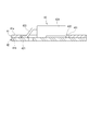
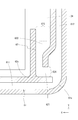
- FIG. 2 is a cross-sectional view taken along line AA in FIG. 1 (connection members are not shown).
- FIG. 2 is a sectional view taken along line BB in FIG. 1 (connection members are not shown).
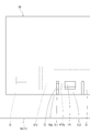
- FIG. 2 is a diagram schematically showing a cross section taken along line CC of FIG. 1. It is the side view which looked at the board
- the height direction (vertical direction) in the following description refers to the direction along the Z axis shown in FIG.
- the front-rear direction means the direction along the Y-axis (the direction in the direction of the arrow is the rear)
- the plane direction means the direction along the XY plane.
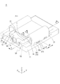
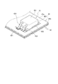
- the board unit 1 is an in-vehicle electric component in which a board 41 is housed in a case 1a.
- the case 1 a of the substrate unit 1 according to the present embodiment includes a first case body 10 and a second case body 20.
- the first case body 10 is formed with a first space S1 (corresponding to the accommodation space in the present invention) in which an object is accommodated.
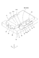
- the upper part of the first space S1 formed in the first case body 10 is covered by the second case body 20 (see FIGS. 3 and 4). That is, it can be said that the first space S ⁇ b> 1 is a space constituted by the first case body 10 and the second case body 20.
- the first space S1 in the present embodiment is a space that is flat in the plane direction.
- a substrate 41 that is an object to be accommodated and a conductive member 42 fixed thereto (hereinafter also referred to as a substrate / conductive member set 40) are accommodated in the first space S1.
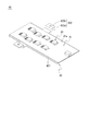
- the substrate / conductive member set 40 shown in FIGS. 5 to 7 includes a substrate 41 and a conductive member 42.
- the substrate 41 has a conductive pattern formed on one surface 41a (upper surface, which corresponds to the mounting surface in the present invention).
- the conductive path formed by the conductive pattern is a control conductive path (a part of the circuit), and the current flowing is smaller than the conductive path (a part of the circuit) formed by the conductive member 42.
- the conductive member 42 has a main body 421 fixed to the other surface 41 b (lower surface) of the substrate 41 and an extending portion 422 extending from the main body 421.
- the conductive member 42 is formed into a predetermined shape by pressing or the like.
- the main body 421 of the conductive member 42 constitutes a conductive path for electric power, which is a portion through which a relatively large current (larger than the conductive path constituted by the conductive pattern) flows.
- the main-body part 421 of the conductive member 42 has a several part which comprises a conductive path.
- the conductive member 42 (main body 421) is also called a bus bar (bus bar plate) or the like.
- the main body 421 of the conductive member 42 is fixed to the other surface 41b of the substrate 41 via, for example, an insulating adhesive or an adhesive sheet. Thereby, the board
- the extended part 422 of the conductive member 42 is a part formed so as to stand up from the main body part 421.
- the extending portion 422 includes a portion (base end portion 422a) extending upward from the main body portion 421 and a portion (front end) that is bent from the tip end (upper end) of the base end portion 422a and extends along the planar direction. Part 422b).
- the conductive member 42 in the present embodiment has a plurality of extending portions 422. Each extending portion 422 is integral with any of the above-described separate and independent portions of the main body 421. In this embodiment, one separate and independent part and one extending part 422 are connected.
- each extending portion 422 serves as a portion (input terminal portion or output terminal portion) for connecting the connection member 50.
- the board / conductive member group 40 (conductive member 42) and the external device are electrically connected via the connection member 50.
- the electronic component 43 has an element body 431 and a terminal portion.
- a plurality of electronic components 43 are mounted on the board / conductive member set 40. At least some of the terminals of the specific electronic component 43 are electrically connected to the main body 421 of the conductive member 42 through the opening 411 formed in the substrate 41.
- An example of a terminal in which a part of such a terminal is electrically connected to the main body 421 of the conductive member 42 is a transistor (FET).
- FET transistor
- the drain terminal 432 and the source terminal 433 of the transistor are connected to the main body 421 of the conductive member 42, and the gate terminal 434 is connected to the conductive pattern of the substrate 41.
- At least a part of the electronic component 43 is such that at least a part of the terminals are directly electrically connected to the conductive member 42.
- an electronic component 43 in which all the terminals are directly electrically connected to the conductive pattern formed on the substrate 41 (at least some of the terminals are not directly electrically connected to the conductive member 42). May be present.
- the substrate / conductive member set 40 thus configured is accommodated in the first space S1 as described above (see FIGS. 3 and 4). Strictly speaking, the portion of the substrate / conductive member set 40 excluding the extended portion 422 is accommodated in the first space S1.
- the first case body 10 constituting the first space S ⁇ b> 1 includes a frame member 11 and a heat radiating member 19.
- the frame member 11 has a substantially rectangular shape, and an inner region thereof is the first space S1.
- the heat radiating member 19 is a flat member formed of a material having high thermal conductivity (such as copper), and is fixed to the lower side of the frame member 11. The heat dissipation member 19 is fixed so as to cover the lower opening of the frame member 11.
- a flat first space S1 extending in the plane direction is formed.
- the frame member 11 is a member constituting the side wall of the first space S1
- the heat radiating member 19 is a member constituting the bottom wall of the first space S1.
- At least a part of the main body 421 of the conductive member 42 is joined to the heat radiating member 19.
- the main-body part 421 of the electrically-conductive member 42 and the thermal radiation member 19 are good to join through the insulating material with high heat conductivity.
- the substrate / conductive member set 40 is placed on the bottom surface (heat dissipating member 19) of the first case body 10 with the conductive member 42 facing down. That is, the substrate 41 is supported by the first case body 10 (indirectly via the conductive member 42).
- the frame member 11 is provided with a base portion 12 and a male screw portion 13 protruding upward from the base portion 12 (see FIG. 2 and the like).
- a through hole through which the male screw portion 13 can be passed is formed at the distal end portion 422b of the extending portion 422 of the conductive member 42.
- the third case body 30 is fixed to the first case body 10 so as to cover the base portion 12. Since at least a part of the connection member 50 (terminal 51) is located on the base portion 12 together with the tip portion 422b of the extending portion 422, both are covered with the third case body 30. From another viewpoint, at least a part of the distal end portion 422b of the extending portion 422 and the connection member 50 is in the second space S2 configured by the third case body 30 and the first case body 10 (frame member 11). It means that they are housed.
- a waterproof wall 32 is formed on the first space S1 side of the third case body 30 to prevent water that has entered the second space S2 from entering the first space S1.
- the protrusion 24 formed in the second case body 20 suppresses the water that has entered the first space S1 from flowing to the substrate 41 side.
- the opening of the first space S1 formed in the first case body 10 is covered with the second case body 20. That is, it can be said that the second case body 20 constitutes the first space S1 together with the first case body 10, and constitutes the upper wall of the first space S1.
- the second case body 20 is fixed to the frame member 11 of the first case body 10.
- the second case body 20 is formed in a shape that covers at least a part of the upper surface of the frame member 11 excluding the base portion 12.
- the outer wall of the second case body 20 has a shape such that a part thereof is cut out, and due to the presence of the cut-out portion (notch portion 22), the second case body 10 has a second case. Even in a state where the body 20 is fixed, a gap through which the extended portion 422 can be passed is secured (see FIG. 2 and the like).
- the outer wall 21 of the second case body 20 is provided with a locking hole 211 that is engaged with the locking protrusion 16 provided in the first case body 10. Both case bodies are integrated by the engagement of the locking protrusion 16 and the locking hole 211.
- the second case body 20 in the present embodiment is provided with a connector portion 23 for electrically connecting the substrate 41 and an external device.
- the second case body 20 is provided with a protrusion 24 (see FIGS. 3 and 4).
- the protrusion 24 is a protrusion that protrudes into the first space S1. Specifically, the protrusion protrudes downward from the upper wall of the second case body 20.
- the second case body 20 in the present embodiment has at least protrusions 24 extending in the front-rear direction on the inner side of the outer wall portions 21 on both sides in the width direction.
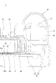
- the protrusion 24 intersects a surface X (a surface obtained by extending the one surface 41a as it is) along the one surface 41a that is the mounting surface of the substrate 41. That is, the leading edge of the protrusion 24 is positioned below the one surface 41 a of the substrate 41. Further, a gap through which a part of the conductive member 42 can pass is present between the protruding portion 24 and the bottom surface of the first case body 10 (the upper surface of the heat radiating member 19). That is, there is a gap for pulling out the extended portion 422 to the outside.
- the substrate / conductive member set 40 is configured to be placed on the bottom surface of the first case body 10 so that the substrate 41 is positioned on the upper side and the conductive member 42 is positioned on the lower side. Even if it is formed so as to intersect one surface 41a (upper surface), a part of the conductive member 42 can be pulled out.
- the protrusion 24 in the present embodiment functions as a water blocking wall that suppresses (blocks) the flow of water to the substrate 41 side. Since the protrusion 24 is formed so that the leading edge thereof is located below the mounting surface of the substrate 41, water adheres to the mounting surface of the substrate 41 and suppresses problems such as a short circuit. can do.
- the substrate / conductive member set 40 (excluding a part of the extended portion 422) is formed in the first space S1, and the portion (tip portion 422b) of the extended portion 422 is set in the second space S2.
- a part (terminal 51) of the connecting member 50 is accommodated.
- the case 1a in the present embodiment is provided with a structure for draining water generated by condensation or the like, or water that has entered from outside into the first space S1 in which the substrate / conductive member set 40 is accommodated.
- the structure of the drainage structure is as follows.
- the drainage structure demonstrated below demonstrates what was provided in the width direction right front of case 1a, such a drainage structure is provided in the width direction left front, the width direction right back, and the width direction left rear. It may be.
- the drainage structure will be described with reference to FIGS.
- a drainage flow path 60 extending from the first space S1 is formed.
- the drainage channel 60 includes a first channel portion 61 and a second channel portion 62.
- the first flow path portion 61 is a flow path whose both ends are connected to the outlets (the first outlet 71 and the second outlet 72) (open to the outside).
- the second flow path portion 62 is a flow path having one end connected to the first space S ⁇ b> 1 and the other end connected to an intermediate portion of the first flow path portion 61 (between the first outlet 71 and the second outlet 72).
- the first outlet 71 of the first flow path portion 61 is provided on the center side in the width direction of the case 1a.
- the height of the first outlet 71 is the same as the height of one end of the first flow path portion 61. More specifically, it is located at the same height as the boundary portion between the first case body 10 and the third case body 30 (see FIGS. 1 and 2).
- the first flow path portion 61 extends from the first outlet 71 toward the outer side in the width direction (right side), and is bent so as to go backward in the middle. That is, the first flow path portion 61 includes a first portion 611 extending along the width direction and a second portion 612 extending along the front-rear direction (see FIG. 10 and the like).
- a portion connected to the second flow path portion 62 is located near the boundary between the first portion 611 and the second portion 612, that is, in the vicinity of the bent portion of the first flow path portion 61. That is, a boundary portion with the second flow path portion 62 exists on the first portion 611 side in the second portion 612 of the first flow path portion 61. It can be said that the 1st flow path part 61 contains the part (1st bending part 61c) bent to the 2nd flow path part 62 side between the part and the 1st exit 71 which the 2nd flow path part 62 connects.
- the second outlet 72 of the first flow path portion 61 is provided on the center side in the front-rear direction of the case 1a.
- the second portion 612 is connected to a space portion 613 formed in the first case body 10 (frame member 11).
- the space 613 is connected to the second outlet 72 (see FIGS. 9 to 11 and the like).
- the first flow path portion 61 in the present embodiment includes the first portion 611, the second portion 612, and the space portion 613.
- the drainage flow path 60 may include a non-elongated portion such as a groove as long as water can flow (may include a clustered region such as the space 613).
- the 1st part 611 and the 2nd part 612 are the grooves which opened upwards, and the 2nd case body 20 is provided so that the said opening may be covered.
- the space portion 613 is a portion covered with the third case body 30.
- the space portion 613 is connected to the second outlet 72.
- a hole (space) that becomes the second outlet 72 is formed in the third case body 30.
- a part of the slit 311 formed in the third case body 30 functions as the second outlet 72.
- the slit 311 is formed so that the lock piece 312 can be deformed (cantilevered), and the slit 311 is used as the second outlet 72 for drainage (FIG. 9 and the like). reference).
- a step is formed on at least a part of the outer edge of the frame member 11 constituting the first case body 10. Specifically, a step 15 that is recessed so as to be lower than the bottom of the bottom surface (first portion 611, second portion 612, space portion 613) of the first flow path portion 61 is formed. Further, the frame member 11 constituting the first case body 10 is formed with a support protrusion 14 that is a protrusion protruding upward. The upper surface of the support protrusion 14 becomes the base portion 12. A lock protrusion 141 protruding outward is formed on the outer surface of the support protrusion 14. The outer surface of the support protrusion 14 is the same (same surface) as the surface along the vertical direction of the step portion 15.
- the frame member 11 is formed with a groove (lateral groove 613a) in which a part of the base portion of the support protrusion 14 is cut when viewed from the side.
- the lateral groove 613a is a part of the space portion 613 (see FIGS. 2 and 9).
- the third case body 30 is pressed against the frame member 11 so that the inner surface of the outer wall portion 31 faces the surface along the vertical direction of the stepped portion 15 from the outer surface of the support protrusion 14, thereby the outer wall portion 31.
- the lock piece 312 formed in the contact with the lock protrusion 141 is elastically deformed.
- the lock piece portion 312 returns to its original shape, and the lock protrusion 141 is fitted into the through hole formed in the lock piece portion 312. Thereby, the 3rd case body 30 is fixed to the 1st case body 10 (frame member 11).
- a part on the front end side of the outer wall portion 31 of the third case body 30 enters the stepped portion 15. That is, a part of the inner surface on the front end side of the outer wall portion 31 of the third case body 30 is in close contact with the surface along the vertical direction of the step portion 15, and the front end (tip edge) of the outer wall portion 31 of the third case body 30.
- At least a part of 31 a) is located at a position where the space portion 613 (lateral groove 613 a) of the first flow path portion 61 provided in the frame member 11 is continuous with the slit 311, that is, at a position lower than the second outlet 72.
- the tip edge 31a of the portion of the outer wall 31 of the third case body 30 where the slit 311 (lock piece 312) is formed is positioned lower than the second outlet 72.
- the boundary portion (boundary line along the front-rear direction) of the first case body 10 and the third case body 30 on the outer surface in the width direction of the case 1 a is lower than the second outlet 72. It is located in. Since the slit 311 is formed so as to extend in the vertical direction from the tip of the outer wall portion 31 of the third case body 30, a part of the upper side of the slit 311 is connected to the space portion 613 (lateral groove 613 a) of the first flow path portion 61. Overlapping structure (see FIG. 9 etc.).
- the first outlet 71 of the first flow path portion 61 is formed at the same height as the boundary portion between the first case body 10 and the second case body 20 (see FIGS. 1 and 2).
- the 2nd exit 72 of the 1st channel part 61 is located in a position higher than the boundary part of the 1st case body 10 and the 3rd case body 30 (refer to Drawing 9 grade). More specifically, the water to enter from the boundary portion between the first case body 10 and the second case body 20 (the gap between the two case bodies) may enter the inside from the first outlet 71 as it is, The water to enter from the boundary portion between the one case body 10 and the third case body 30 (the gap between the two case bodies) is blocked by the step portion 15. That is, the risk of water entering through the second outlet 72 is much lower than the risk of water entering through the first outlet 71.
- the second flow path portion 62 is a flow path that connects the first space S1 and the first flow path portion 61.
- the second flow path portion 62 is bent. Specifically, it includes a first portion 621 in which water that has entered from the first flow path portion 61 flows straight, and a second portion 622 that is bent from the first portion 621 toward the first space S1. A boundary portion between the first portion 621 and the second portion 622 is bent (second bent portion 62c) (see FIG. 10, FIG. 11, etc.).
- the first portion 621 is along the width direction
- the second portion 622 is along the front-rear direction.
- the second flow path portion 62 needs to exert an effect of suppressing the ingress of water into the first space S1 while exhibiting an effect of smoothly discharging the water in the first space S1. Therefore, the size of the flow channel side opening 624 facing the first flow channel portion 61 in the second flow channel portion 62 is set smaller than the size of the space side opening 623 facing the first space S1 (see FIG. 11 and the like). . Thereby, the water in the first space S ⁇ b> 1 is likely to enter the second flow path portion 62, and the water in the first flow path portion 61 is difficult to enter the second flow path portion 62.
- a part of width direction both sides of the protrusion part 24 has penetrated in the said 2nd flow-path part 62 (refer FIG. 10, FIG. 11, etc.). Specifically, a part of both sides in the width direction of the protruding part 24 enters the second flow path part through the space side opening of the second flow path part.
- the movement of the water that has entered the first space S ⁇ b> 1 toward the substrate 41 is restricted by the protrusion 24. Therefore, the water flows through a gap between the protruding portion 24 and the inner wall surface of the first case body 10 (frame member 11). In other words, it flows through a flow path formed between the protruding portion 24 and the inner wall surface of the first case body 10 (frame member 11).
- the protrusion 24 in this embodiment not only functions as a water blocking wall for preventing water from flowing to the substrate 41 side, but also guides water to the drainage flow path 60 together with the first case body 10. It also functions as a member.
- the substrate unit 1 according to the embodiment includes the first case body 10, the second case body 20, and the third case body 30, but the number of case bodies constituting the case 1a
- the specific shape and the like of each case body can be changed as appropriate.
- substrate unit 1 concerning the said embodiment demonstrated that the board
- the accommodation accommodated in 1st space S1 is the board
- what is accommodated in 2nd space S2 may be what.
- the second space S2 may not be provided.
- the protruding portion 24 is provided on the outer side in the width direction of the substrate 41. However, if it is outside the substrate 41, the position where the protruding portion 24 is provided and its size (length). Can be appropriately changed.
- the protruding portion 24 may be provided so as to surround the periphery of the substrate 41.
Landscapes
- Engineering & Computer Science (AREA)
- Microelectronics & Electronic Packaging (AREA)
- Casings For Electric Apparatus (AREA)
- Connection Or Junction Boxes (AREA)
Abstract
内部に浸入した水が基板の実装面に到達してしまうのを抑制することができる簡易な構造の基板ユニットを提供すること。 基板41と、前記基板41が支持される第一ケース体10と、前記第一ケース体10と一体化され、前記基板41の実装面41a側に設けられる第二ケース体20と、を備え、前記第二ケース体20には、前記第一ケース体10と前記第二ケース体20によって構築される前記基板41が収容される収容空間S1内に突出し、前記基板10の実装面41aに沿う面と交差する突出部24が設けられていることを特徴とする基板ユニット。
Description
本発明は、ケースおよびこのケース内に収容された基板を有する基板ユニットに関する。
下記特許文献1等に記載されるように、電気機器を収容する車載用のケース等では、水の浸入によって収容物である電気機器の故障を防止する防水構造が施される。
上記特許文献1のように、シール部材によってケース内部を密閉等する手法では、製造コストが増加してしまう。
本発明が解決しようとする課題は、内部に浸入した水が基板の実装面に到達してしまうのを抑制することができる簡易な構造の基板ユニットを提供することである。
上記課題を解決するために本発明にかかる基板ユニットは、基板と、前記基板が支持される第一ケース体と、前記第一ケース体と一体化され、前記基板の実装面側に設けられる第二ケース体と、を備え、前記第二ケース体には、前記第一ケース体と前記第二ケース体によって構築される前記基板が収容される収容空間内に突出し、前記基板の実装面に沿う面と交差する突出部が設けられていることを特徴とする。
前記基板の実装面の反対側の面に固定された板状の部材であって、導電路を構成する導電部材を備え、前記突出部と前記第一ケース体の底面との間を通って、前記導電部材の一部が前記収容空間の外側に引き出されている。
前記突出部の一部が、前記第一ケース体に形成された排水用流路の内側に入り込んでいるとよい。
本発明にかかる基板ユニットでは、第二ケース体には、収容空間内に突出し、基板の実装面に沿う面と交差する突出部が設けられているため、収容空間内に浸入した水が基板側に流れるのを(水が実装面に到達するのを)抑制することができる。突出部は、第一ケース体とともに収容空間を構成する第二ケース体に形成することができるため、部品点数の増加等、構造の複雑化を招くこともない。
基板の実装面の反対側の面に導電部材が固定される場合、突出部と第一ケース体の底面との間を通して導電部材の一部を外部に引き出すことができる。
突出部の一部が、第一ケース体に形成された排水用流路の内側に入り込んだ構造とすれば、収容空間内に浸入した水が、突出部に誘導されることにより排水用流路から外部に排出されやすくなる。つまり、突出部は、水が基板側に流れるのを抑制する機能だけでなく、収容空間内に浸入した水を外部に排出するのを促進する機能を発揮する。
以下、本発明の実施形態について図面を参照しつつ詳細に説明する。なお、特に明示した場合を除き、以下の説明における高さ方向(上下方向)とは、図1等に示すZ軸に沿う方向(矢印の向く方向側を上とする)をいい、幅方向とはX軸に沿う方向をいい、前後方向とはY軸に沿う方向(矢印の向く方向側を後とする)をいい、平面方向とはXY平面に沿う方向をいうものとする。なお、これらの方向は基板ユニット1の設置方向を限定するものではないが、本実施形態にかかる基板ユニット1は、基本的には第一ケース体10が下側に、第三ケース体30が上側に位置するように配置されるものである。
図1および図2に示すように、本発明の一実施形態にかかる基板ユニット1は、基板41がケース1a内に収容された車載用の電気部品である。本実施形態にかかる基板ユニット1のケース1aは、第一ケース体10および第二ケース体20を有する。
第一ケース体10には、被収容物が収容される第一空間S1(本発明における収容空間に相当する)が形成される。第一ケース体10に形成された第一空間S1の上方は、第二ケース体20によって覆われる(図3、図4等参照)。つまり、第一空間S1は、第一ケース体10と第二ケース体20によって構成される空間であるともいえる。本実施形態における第一空間S1は、平面方向に平たい空間である。
本実施形態では、第一空間S1内に被収容物である基板41およびそれに固定された導電部材42(以下、基板・導電部材組40と称することもある)が収容される。
図5~図7に示す基板・導電部材組40は、基板41および導電部材42を備える。基板41は、一方の面41a(上側の面。本発明における実装面に相当する)に導電パターンが形成されたものである。当該導電パターンが構成する導電路は制御用の導電路(回路の一部)であり、導電部材42が構成する導電路(回路の一部)よりも流れる電流が相対的に小さい。
導電部材42は、基板41の他方の面41b(下側の面)に固定された本体部421および本体部421から延びる延設部422を有する。導電部材42は、プレス加工等によって所定の形状に形成される。導電部材42の本体部421は、相対的に大きな(導電パターンによって構成される導電路よりも大きな)電流が流れる部分である電力用の導電路を構成する。なお、導電路の具体的な構成については、説明および図示を省略するが、導電部材42の本体部421は導電路を構成する複数の部分を有する。各部分は短絡しないように別個独立しており、基板41に固定されることによって一体となっている。複数の部分は、基板41に固定される前は余長部分によって繋がっており、基板41に固定された後当該余長部分が切り取られることによりそれぞれが別個独立した状態(直接接触していない状態)となる。導電部材42(本体部421)は、バスバー(バスバープレート)等とも称される。導電部材42の本体部421は、例えば絶縁性の接着剤や接着シートなどを介して、基板41の他方の面41bに固定される。これにより、基板41と導電部材42が一体化されている。
導電部材42の延設部422は、本体部421から起立するよう形成された部分である。本実施形態における延設部422は、本体部421から上方に向かって延びる部分(基端部422a)と、基端部422aの先端(上端)から屈曲し、平面方向に沿って延びる部分(先端部422b)を有する。本実施形態における導電部材42は、複数の延設部422を有する。各延設部422は、上述した本体部421の別個独立した部分のいずれかと一体である。本実施形態では、一つの別個独立した部分と一つの延設部422が繋がっている。各延設部422の先端部422bは、接続部材50を接続するための部分(入力端子部または出力端子部)となる。当該接続部材50を介して、基板・導電部材組40(導電部材42)と外部機器とが電気的に接続されることとなる。
電子部品43は、素子本体431および端子部を有する。基板・導電部材組40には複数の電子部品43が実装されている。特定の電子部品43の少なくとも一部の端子は、基板41に形成された開口411を通じて導電部材42の本体部421に電気的に接続される。このような端子の一部が導電部材42の本体部421に電気的に接続される端子としては、トランジスタ(FET)が例示できる。トランジスタのドレイン端子432およびソース端子433は、導電部材42の本体部421に接続され、ゲート端子434は基板41の導電パターンに接続される。このように、電子部品43のうちの少なくとも一部は、その少なくとも一部の端子が、導電部材42に対し直接電気的に接続されるものである。別の見方をすれば、全ての端子が基板41に形成された導電パターンに直接電気的に接続される電子部品43(少なくとも一部の端子が導電部材42に対し直接電気的に接続されないもの)が存在していてもよいということである。
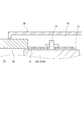
このように構成される基板・導電部材組40は、上述したように第一空間S1内に収容される(図3、図4等参照)。厳密には、基板・導電部材組40のうち、延設部422を除く部分が第一空間S1内に収容される。本実施形態では、第一空間S1を構成する第一ケース体10は、枠部材11および放熱部材19を備える。枠部材11は、略方形状を呈し、その内側の領域が第一空間S1となる。放熱部材19は、熱伝導性の高い材料(銅等)で形成された平板状の部材であって、枠部材11の下側に固定される。放熱部材19は、枠部材11の下側の開口を覆うように固定される。このような枠部材11および放熱部材19により、平面方向に広がる平たい第一空間S1が形成される。枠部材11は第一空間S1の側壁を、放熱部材19は第一空間S1の底壁を構成する部材であるともいえる。導電部材42の本体部421の少なくとも一部は放熱部材19に接合される。これにより、基板・導電部材組40から発生した熱の少なくとも一部は、放熱部材19を介して外部に放出される。なお、導電部材42の本体部421と放熱部材19は、熱伝導性の高い絶縁材料を介して接合されているとよい。このように、基板・導電部材組40は、導電部材42を下にして、第一ケース体10の底面(放熱部材19)上に載置されている。つまり、基板41は、(導電部材42を介して間接的に)第一ケース体10に支持されている。
枠部材11には、土台部12およびこの土台部12から上方に向かって突出した雄ねじ部13が設けられている(図2等参照)。導電部材42の延設部422の先端部422bには、雄ねじ部13を通すことができる貫通孔が形成されている。先端部422bに形成された貫通孔に雄ねじ部13を通すとともに、接続部材50の端子51に形成された貫通孔に雄ねじ部13を通し、ナット等を雄ねじ部13に螺合させることにより、先端部422bと端子51が土台部12に押しつけられて両者が密着する。これにより、導電部材42と接続部材50が電気的に接続された状態となる(図8等参照)。接続部材50は、電線52の先端に端子51が接続されたもの等が例示できる。
第三ケース体30は、土台部12を覆うように第一ケース体10に固定される。土台部12上では、延設部422の先端部422bとともに接続部材50(端子51)の少なくとも一部が位置することとなるため、両者が第三ケース体30に覆われるということとなる。別の見方をすれば、延設部422の先端部422bと接続部材50の少なくとも一部が、第三ケース体30と第一ケース体10(枠部材11)によって構成される第二空間S2に収容されているということである。
本実施形態では、第三ケース体30における第一空間S1側には、第二空間S2に入り込んだ水が第一空間S1に浸入するのを抑制するための防水壁32が形成されている。詳細を後述するように、本実施形態では、第二ケース体20に形成された突出部24によって、第一空間S1内に浸入した水が基板41側に流れるのを抑制しているが、上記防水壁32を構築することにより、第一空間S1内に水が浸入すること自体を抑制することができる。
第一ケース体10に形成される第一空間S1の開口は、第二ケース体20に覆われる。つまり、第二ケース体20は第一ケース体10とともに第一空間S1を構成するものであって、第一空間S1の上壁を構成するものであるともいえる。第二ケース体20は、第一ケース体10の枠部材11に固定される。第二ケース体20は、土台部12を除く枠部材11の上面の少なくとも一部を覆うような形状に形成されている。第二ケース体20の外壁は、その一部が切り欠かれたような形状をしており当該切り欠かれた部分(切欠き部22)の存在により、第一ケース体10に対し第二ケース体20が固定された状態においても、延設部422を通すことができる隙間が確保される(図2等参照)。
第二ケース体20の外壁部21には、第一ケース体10に設けられた係止突起16に係合させられる係止孔211が設けられている。当該係止突起16と係止孔211の係合により両ケース体が一体化される。
第一ケース体10に対し第二ケース体20が固定された状態において、第二ケース体20の切り欠かれた部分と第一ケース体10の間には上記隙間が存在しており、当該隙間に延設部422が通される。これにより、延設部422の先端部422bは土台部12上に位置した状態となる。なお、本実施形態における第二ケース体20には、基板41と外部機器を電気的に接続するためのコネクタ部23が設けられている。
第二ケース体20には突出部24が設けられている(図3、図4等参照)。突出部24は、第一空間S1内に突出する突起である。具体的には、第二ケース体20の上壁から下方に向かって突出する突起である。本実施形態における第二ケース体20は、少なくとも、幅方向両側の外壁部21より内側に前後方向に延びる突出部24を有する。
当該突出部24は、基板41の実装面である一方の面41aに沿う面X(一方の面41aをそのまま延長させた面)と交差する。つまり、突出部24の先端縁は、基板41の一方の面41aよりも下方に位置する。また、突出部24と第一ケース体10の底面(放熱部材19の上面)との間には、導電部材42の一部を通すことができる隙間が存在する。つまり、上記延設部422を外部に引き出すための隙間が存在する。基板・導電部材組40は、基板41が上側で導電部材42が下側に位置するようにして第一ケース体10の底面上に載置される構造であるため、突出部24を基板41の一方の面41a(上側の面)に交差するように形成しても、導電部材42の一部を外部に引き出すことができる。
このような突出部24が形成されていれば、第一空間S1内に浸入した水が基板41側に流れるのを抑制することができる。つまり、本実施形態における突出部24は、水が基板41側に流れるのを抑制(阻止)する止水壁として機能する。当該突出部24は、その先端縁が基板41の実装面より下方に位置するように形成されているから、基板41の実装面に水が付着し、短絡等の不具合が生じてしまうのを抑制することができる。
このように、第一空間S1内には基板・導電部材組40(延設部422の一部を除く)が、第二空間S2内には延設部422の一部(先端部422b)と接続部材50の一部(端子51)が収容される。本実施形態におけるケース1aには、基板・導電部材組40が収容された第一空間S1内に凝結等によって発生した水や外部から入り込んだ水を排水するための構造が設けられている。当該排水構造の構成は以下の通りである。なお、以下で説明する排水構造は、ケース1aの幅方向右側前方に設けられたものについて説明するが、このような排水構造が幅方向左側前方、幅方向右側後方、幅方向左側後方に設けられていてもよい。
図9~図11等を参照して排水構造を説明する。第一ケース体10には、第一空間S1から延びる排水用流路60が形成されている。排水用流路60は、第一流路部61および第二流路部62を含む。第一流路部61は、両端が出口(第一出口71、第二出口72)に繋がった(外部に開放された)流路である。第二流路部62は、一端が第一空間S1に、他端が第一流路部61の途中部位(第一出口71と第二出口72の間)に繋がった流路である。
第一流路部61の第一出口71は、ケース1aの幅方向中央側に設けられている。第一出口71の高さは、第一流路部61の一方端の高さと同じである。より具体的には、第一ケース体10と第三ケース体30の境界部分と同じ高さに位置する(図1、図2等参照)。第一流路部61は、第一出口71から幅方向外側(右側)に向かって延び、途中で後方に向かうように屈曲している。つまり、第一流路部61は、幅方向に沿って延びる第一の部分611と、前後方向に沿って延びる第二の部分612を有する(図10等参照)。第一の部分611と第二の部分612の境界部、すなわち第一流路部61の屈曲した部分の近傍に、第二流路部62と繋がった部分が位置する。つまり、第一流路部61の第二の部分612における第一の部分611側に、第二流路部62との境界部分が存在する。第一流路部61は、第二流路部62が繋がる部分と第一出口71との間に、第二流路部62側に屈曲した部分(第一屈曲部61c)を含むものであるといえる。
第一流路部61の第二出口72は、ケース1aの前後方向中央側に設けられている。第二の部分612は、第一ケース体10(枠部材11)に形成された空間部613に繋がっている。当該空間部613が第二出口72に繋がっている(図9~図11等参照)。つまり、本実施形態における第一流路部61は、第一の部分611、第二の部分612および空間部613から構成されるものである。つまり、排水用流路60は、水が流れることが可能な領域であれば溝のような細長い形状でない部分を含んでいてもよい(空間613のようなまとまった領域を含んでいてもよい)。第一の部分611および第二の部分612は、上方が開口した溝であり、当該開口を覆うように第二ケース体20が設けられる。空間部613は、第三ケース体30に覆われる部分である。
上述したように、空間部613は第二出口72に繋がっている。本実施形態では、当該第二出口72となる孔(空間)が第三ケース体30に形成されている。具体的には、第三ケース体30に形成されたスリット311の一部が、当該第二出口72として機能する。スリット311は、ロック片部312を変形可能とする(片持ち状とする)ために形成されるものであり、当該スリット311を、排水用の第二出口72として利用している(図9等参照)。
第一ケース体10を構成する枠部材11の外縁の少なくとも一部には、段差が形成されている。具体的には、第一流路部61の底面(第一の部分611、第二の部分612、空間部613)の底面よりも低くなるように凹んだ段差部15が形成されている。また、第一ケース体10を構成する枠部材11には、上方に向かって突出した突起である支持突起14が形成されている。当該支持突起14の上面が上記土台部12となる。支持突起14の外面には、外側に向かって突出したロック突起141が形成されている。支持突起14の外面は段差部15の上下方向に沿う面と同一(面一)である。枠部材11には、側方から見て、支持突起14の根元部分の一部が抉られたような溝(横溝613a)が形成されている。当該横溝613aは空間部613の一部である(図2、図9等参照)。
第三ケース体30は、その外壁部31の内側の面を、上記支持突起14の外面から段差部15の上下方向に沿う面に対向させるようして枠部材11に押しつけることで、外壁部31に形成されたロック片部312がロック突起141に接触して弾性変形する。さらに第三ケース体30を枠部材11に押しつけると、ロック片部312が元の形状に戻り、ロック片部312に形成された貫通孔にロック突起141が嵌まり込む。これにより、第三ケース体30が第一ケース体10(枠部材11)に固定される。第三ケース体30が第一ケース体10に固定された状態において、第三ケース体30の外壁部31における先端側の一部は、段差部15に入り込む。つまり、第三ケース体30の外壁部31における先端側の一部の内側の面は、段差部15の上下方向に沿う面に密接し、第三ケース体30の外壁部31の先端(先端縁31a)の少なくとも一部は、枠部材11に設けられた第一流路部61の空間部613(横溝613a)がスリット311に連なる部分、すなわち第二出口72よりも低い位置に位置する。
より具体的には、第三ケース体30の外壁部31におけるスリット311(ロック片部312)が形成された部分の先端縁31aは、第二出口72よりも低い位置に位置する。さらに別の見方をすれば、ケース1aの幅方向外側の面における、第一ケース体10と第三ケース体30の境界部分(前後方向に沿う境界線)は、第二出口72よりも低い位置に位置するということである。スリット311は、第三ケース体30の外壁部31の先端から上下方向に延びるように形成されているため、スリット311の上側の一部が第一流路部61の空間部613(横溝613a)と重なる構造となる(図9等参照)。
第一流路部61の第一出口71は、第一ケース体10と第二ケース体20の境界部分と同じ高さに形成されている(図1、図2等参照)。一方、第一流路部61の第二出口72は、第一ケース体10と第三ケース体30の境界部分よりも高い位置に位置する(図9等参照)。より具体的には、第一ケース体10と第二ケース体20の境界部分(両ケース体の隙間)から浸入しようとする水はそのまま第一出口71から内部に浸入するおそれがある一方、第一ケース体10と第三ケース体30の境界部分(両ケース体の隙間)から浸入しようとする水は段差部15によって遮られることとなる。つまり、第二出口72を通じて水が浸入するおそれは、第一出口71を通じて水が浸入するおそれよりもかなり低いということである。
第二流路部62は、第一空間S1と第一流路部61とを繋ぐ流路である。当該第二流路部62は屈曲している。具体的には、第一流路部61から浸入した水が真っすぐ流れる第一の部分621と、そこから屈曲して第一空間S1に向かう第二の部分622とを含む。第一の部分621と第二の部分622の境界部分は屈曲(第二屈曲部62c)している(図10、図11等参照)。本実施形態では、第一の部分621は幅方向に沿い、第二の部分622は前後方向に沿う。このように、第一流路部61から第二流路部62に浸入した水がそのまま真っすぐ流れて第一空間S1に到達しないような構造とすることで、第二流路部62を通じた第一空間S1内への水の浸入が抑制される。
また、第二流路部62は、第一空間S1内の水をスムーズに排出する作用を発揮させつつ、第一空間S1への水の浸入を抑制する作用を発揮させる必要がある。したがって、第二流路部62における第一流路部61に臨む流路側開口624の大きさを、第一空間S1に臨む空間側開口623の大きさよりも小さく設定している(図11等参照)。これにより、第一空間S1内の水は第二流路部62に浸入しやすく、第一流路部61の水は第二流路部62に浸入しにくい構造となる。
そして、本実施形態では、突出部24の幅方向両側の一部が当該第二流路部62内に入り込んでいる(図10、図11等参照)。具体的には、突出部24の幅方向両側の一部は、第二流路部の空間側開口を通じて第二流路部内に入り込んでいる。第一空間S1内に浸入した水は、基板41側への移動が突出部24によって制限される。そのため、当該水は、突出部24と第一ケース体10(枠部材11)の内壁面との間の隙間を流れる。換言すれば、突出部24と第一ケース体10(枠部材11)の内壁面との間に形成される流路を流れる。そして、その先は、排水用流路60を構成する第二流路部62に繋がっているから、そのまま水が外部に排出されることとなる。つまり、本実施形態における突出部24は、基板41側に水が流れないようにするための止水壁として機能するだけでなく、第一ケース体10とともに、排水用流路60に水を導くための部材としても機能する。
以上、本発明の実施形態について詳細に説明したが、本発明は上記実施形態に何ら限定されるものではなく、本発明の要旨を逸脱しない範囲で種々の改変が可能である。
例えば、上記実施形態にかかる基板ユニット1は、第一ケース体10、第二ケース体20、第三ケース体30を備えるものであることを説明したが、ケース1aを構成するケース体の数や各ケース体の具体的な形状等は適宜変更可能である。
また、上記実施形態にかかる基板ユニット1は、ケース1a内に基板・導電部材組40が収容されたものであることを説明したが、第一空間S1に収容される収容物は基板41単体であってもよい。また、第二空間S2に収容される収容物もどのようなものであってもよい。第二空間S2が設けられていない構成としてもよい。
上記実施形態では、基板41の幅方向外側に突出部24が設けられていることを説明したが、基板41の外側であれば、突出部24が設けられる位置や、その大きさ(長さ)は適宜変更可能である。例えば、基板41の周囲を囲むように突出部24が設けられていてもよい。
Claims (3)
- 基板と、
前記基板が支持される第一ケース体と、
前記第一ケース体と一体化され、前記基板の実装面側に設けられる第二ケース体と、
を備え、
前記第二ケース体には、前記第一ケース体と前記第二ケース体によって構築される前記基板が収容される収容空間内に突出し、前記基板の実装面に沿う面と交差する突出部が設けられていることを特徴とする基板ユニット。 - 前記基板の実装面の反対側の面に固定された板状の部材であって、導電路を構成する導電部材を備え、
前記突出部と前記第一ケース体の底面との間を通って、前記導電部材の一部が前記収容空間の外側に引き出されていることを特徴とする請求項1に記載の基板ユニット。 - 前記突出部の一部が、前記第一ケース体に形成された排水用流路の内側に入り込んでいることを特徴とする請求項1または請求項2に記載の基板ケース。
Priority Applications (2)
| Application Number | Priority Date | Filing Date | Title |
|---|---|---|---|
| CN201680009935.3A CN107432091B (zh) | 2015-02-18 | 2016-01-28 | 基板单元 |
| US15/549,407 US10681826B2 (en) | 2015-02-18 | 2016-01-28 | Substrate unit |
Applications Claiming Priority (2)
| Application Number | Priority Date | Filing Date | Title |
|---|---|---|---|
| JP2015-029622 | 2015-02-18 | ||
| JP2015029622A JP6330686B2 (ja) | 2015-02-18 | 2015-02-18 | 基板ユニット |
Publications (1)
| Publication Number | Publication Date |
|---|---|
| WO2016132839A1 true WO2016132839A1 (ja) | 2016-08-25 |
Family
ID=56688757
Family Applications (1)
| Application Number | Title | Priority Date | Filing Date |
|---|---|---|---|
| PCT/JP2016/052409 WO2016132839A1 (ja) | 2015-02-18 | 2016-01-28 | 基板ユニット |
Country Status (4)
| Country | Link |
|---|---|
| US (1) | US10681826B2 (ja) |
| JP (1) | JP6330686B2 (ja) |
| CN (1) | CN107432091B (ja) |
| WO (1) | WO2016132839A1 (ja) |
Families Citing this family (1)
| Publication number | Priority date | Publication date | Assignee | Title |
|---|---|---|---|---|
| JP7159625B2 (ja) * | 2018-06-07 | 2022-10-25 | 株式会社オートネットワーク技術研究所 | 回路ユニット、電気接続箱 |
Citations (3)
| Publication number | Priority date | Publication date | Assignee | Title |
|---|---|---|---|---|
| JPS6359383U (ja) * | 1986-10-06 | 1988-04-20 | ||
| JP2013176242A (ja) * | 2012-02-27 | 2013-09-05 | Auto Network Gijutsu Kenkyusho:Kk | 電気接続箱 |
| JP2014156168A (ja) * | 2013-02-14 | 2014-08-28 | Autoliv Development Ab | 電子制御ユニット |
Family Cites Families (21)
| Publication number | Priority date | Publication date | Assignee | Title |
|---|---|---|---|---|
| JPS6359383A (ja) | 1986-08-27 | 1988-03-15 | 株式会社 南部電機製作所 | 等級分類装置の動作確認方法及びその装置 |
| JP2004088989A (ja) * | 2002-07-03 | 2004-03-18 | Auto Network Gijutsu Kenkyusho:Kk | 電力回路部の防水方法 |
| JP4114497B2 (ja) * | 2003-02-14 | 2008-07-09 | 住友電装株式会社 | 回路構成体用ケース及び回路構成体の製造方法 |
| JP4381845B2 (ja) * | 2004-02-19 | 2009-12-09 | 株式会社オートネットワーク技術研究所 | ヒューズモジュール |
| DE102004021365A1 (de) * | 2004-03-16 | 2005-10-06 | Robert Bosch Gmbh | Gehäuse für eine elektronische Schaltung und Verfahren zum Abdichten des Gehäuses |
| KR100603382B1 (ko) * | 2004-10-25 | 2006-07-20 | 삼성에스디아이 주식회사 | 플라즈마 디스플레이 장치 |
| DE102005002813B4 (de) * | 2005-01-20 | 2006-10-19 | Robert Bosch Gmbh | Steuermodul |
| JP4474463B2 (ja) * | 2005-03-08 | 2010-06-02 | 株式会社オートネットワーク技術研究所 | 電気接続箱 |
| JP4885693B2 (ja) * | 2006-12-05 | 2012-02-29 | 株式会社オートネットワーク技術研究所 | 電気接続箱 |
| DE102007029913A1 (de) * | 2007-06-28 | 2009-01-02 | Robert Bosch Gmbh | Elektrisches Steuergerät |
| JP5625971B2 (ja) * | 2011-02-08 | 2014-11-19 | 住友電装株式会社 | 電気接続箱用の内部回路構成体およびそれを用いた電気接続箱 |
| JP5785811B2 (ja) * | 2011-08-02 | 2015-09-30 | 矢崎総業株式会社 | 防水ボックス及びそれを備えた電気接続箱 |
| DE102011089474A1 (de) * | 2011-12-21 | 2013-06-27 | Robert Bosch Gmbh | Elektronikmodul für ein Fahrzeug |
| JP5831757B2 (ja) * | 2012-02-27 | 2015-12-09 | 株式会社オートネットワーク技術研究所 | 電気接続箱 |
| JP6035630B2 (ja) * | 2012-05-22 | 2016-11-30 | 矢崎総業株式会社 | 電気接続箱 |
| JP2015187618A (ja) * | 2012-08-06 | 2015-10-29 | シャープ株式会社 | 表示装置 |
| JP2014175365A (ja) | 2013-03-06 | 2014-09-22 | Aisin Kiko Co Ltd | 基板ケース |
| JP6051103B2 (ja) * | 2013-05-23 | 2016-12-27 | 富士通株式会社 | 防水構造及び電子機器 |
| CN203289163U (zh) * | 2013-06-24 | 2013-11-13 | 江门市大长江集团有限公司 | 具有防水结构的电动车充电器 |
| DE102014209185A1 (de) * | 2013-11-14 | 2015-05-21 | Robert Bosch Gmbh | Elektronikmodul für eine Zündeinheit |
| JP3191032U (ja) * | 2014-03-25 | 2014-06-05 | 日立オートモティブシステムズ株式会社 | 自動車用内燃機関制御装置 |
-
2015
- 2015-02-18 JP JP2015029622A patent/JP6330686B2/ja active Active
-
2016
- 2016-01-28 CN CN201680009935.3A patent/CN107432091B/zh active Active
- 2016-01-28 US US15/549,407 patent/US10681826B2/en active Active
- 2016-01-28 WO PCT/JP2016/052409 patent/WO2016132839A1/ja active Application Filing
Patent Citations (3)
| Publication number | Priority date | Publication date | Assignee | Title |
|---|---|---|---|---|
| JPS6359383U (ja) * | 1986-10-06 | 1988-04-20 | ||
| JP2013176242A (ja) * | 2012-02-27 | 2013-09-05 | Auto Network Gijutsu Kenkyusho:Kk | 電気接続箱 |
| JP2014156168A (ja) * | 2013-02-14 | 2014-08-28 | Autoliv Development Ab | 電子制御ユニット |
Also Published As
| Publication number | Publication date |
|---|---|
| CN107432091A (zh) | 2017-12-01 |
| JP2016152339A (ja) | 2016-08-22 |
| US20180035552A1 (en) | 2018-02-01 |
| US10681826B2 (en) | 2020-06-09 |
| CN107432091B (zh) | 2020-08-18 |
| JP6330686B2 (ja) | 2018-05-30 |
Similar Documents
| Publication | Publication Date | Title |
|---|---|---|
| JP5173596B2 (ja) | 電気接続箱 | |
| WO2015194666A1 (ja) | 電気接続箱及びコネクタハウジング | |
| US8389856B2 (en) | Waterproof structure of electrical junction box | |
| CN109196965B (zh) | 基板单元 | |
| WO2016132852A1 (ja) | 基板ユニット | |
| JP6371205B2 (ja) | 電気接続箱の排水構造 | |
| US10653019B2 (en) | Substrate unit | |
| JP6575930B2 (ja) | 基板ユニット | |
| WO2016132839A1 (ja) | 基板ユニット | |
| JP2009290943A (ja) | 電気接続箱 | |
| US11102895B2 (en) | Electrical junction box | |
| JP6287888B2 (ja) | ケース | |
| JP6330685B2 (ja) | ケース | |
| JP5471793B2 (ja) | 電気接続箱 | |
| WO2017064931A1 (ja) | 電気接続箱 | |
| JP2016152339A5 (ja) | ||
| JP2007110852A (ja) | 電気接続箱 | |
| JP5733164B2 (ja) | 回路ユニット | |
| JP6011886B2 (ja) | 電気接続箱 | |
| JP4543330B2 (ja) | 電気接続箱 | |
| JP2010183696A (ja) | 回路構成体および電気接続箱 |
Legal Events
| Date | Code | Title | Description |
|---|---|---|---|
| 121 | Ep: the epo has been informed by wipo that ep was designated in this application |
Ref document number: 16752228 Country of ref document: EP Kind code of ref document: A1 |
|
| DPE2 | Request for preliminary examination filed before expiration of 19th month from priority date (pct application filed from 20040101) | ||
| NENP | Non-entry into the national phase |
Ref country code: DE |
|
| 122 | Ep: pct application non-entry in european phase |
Ref document number: 16752228 Country of ref document: EP Kind code of ref document: A1 |