WO2016132810A1 - 微多孔プラスチックフィルムの製造方法 - Google Patents
微多孔プラスチックフィルムの製造方法 Download PDFInfo
- Publication number
- WO2016132810A1 WO2016132810A1 PCT/JP2016/051780 JP2016051780W WO2016132810A1 WO 2016132810 A1 WO2016132810 A1 WO 2016132810A1 JP 2016051780 W JP2016051780 W JP 2016051780W WO 2016132810 A1 WO2016132810 A1 WO 2016132810A1
- Authority
- WO
- WIPO (PCT)
- Prior art keywords
- sheet
- stretching
- roller
- plastic film
- diluent
- Prior art date
Links
Images

Classifications
-
- B—PERFORMING OPERATIONS; TRANSPORTING
- B29—WORKING OF PLASTICS; WORKING OF SUBSTANCES IN A PLASTIC STATE IN GENERAL
- B29C—SHAPING OR JOINING OF PLASTICS; SHAPING OF MATERIAL IN A PLASTIC STATE, NOT OTHERWISE PROVIDED FOR; AFTER-TREATMENT OF THE SHAPED PRODUCTS, e.g. REPAIRING
- B29C48/00—Extrusion moulding, i.e. expressing the moulding material through a die or nozzle which imparts the desired form; Apparatus therefor
- B29C48/03—Extrusion moulding, i.e. expressing the moulding material through a die or nozzle which imparts the desired form; Apparatus therefor characterised by the shape of the extruded material at extrusion
- B29C48/07—Flat, e.g. panels
- B29C48/08—Flat, e.g. panels flexible, e.g. films
-
- B—PERFORMING OPERATIONS; TRANSPORTING
- B01—PHYSICAL OR CHEMICAL PROCESSES OR APPARATUS IN GENERAL
- B01D—SEPARATION
- B01D67/00—Processes specially adapted for manufacturing semi-permeable membranes for separation processes or apparatus
- B01D67/0002—Organic membrane manufacture
- B01D67/0023—Organic membrane manufacture by inducing porosity into non porous precursor membranes
- B01D67/0025—Organic membrane manufacture by inducing porosity into non porous precursor membranes by mechanical treatment, e.g. pore-stretching
- B01D67/0027—Organic membrane manufacture by inducing porosity into non porous precursor membranes by mechanical treatment, e.g. pore-stretching by stretching
-
- B—PERFORMING OPERATIONS; TRANSPORTING
- B29—WORKING OF PLASTICS; WORKING OF SUBSTANCES IN A PLASTIC STATE IN GENERAL
- B29C—SHAPING OR JOINING OF PLASTICS; SHAPING OF MATERIAL IN A PLASTIC STATE, NOT OTHERWISE PROVIDED FOR; AFTER-TREATMENT OF THE SHAPED PRODUCTS, e.g. REPAIRING
- B29C48/00—Extrusion moulding, i.e. expressing the moulding material through a die or nozzle which imparts the desired form; Apparatus therefor
- B29C48/25—Component parts, details or accessories; Auxiliary operations
- B29C48/30—Extrusion nozzles or dies
- B29C48/305—Extrusion nozzles or dies having a wide opening, e.g. for forming sheets
-
- B—PERFORMING OPERATIONS; TRANSPORTING
- B29—WORKING OF PLASTICS; WORKING OF SUBSTANCES IN A PLASTIC STATE IN GENERAL
- B29C—SHAPING OR JOINING OF PLASTICS; SHAPING OF MATERIAL IN A PLASTIC STATE, NOT OTHERWISE PROVIDED FOR; AFTER-TREATMENT OF THE SHAPED PRODUCTS, e.g. REPAIRING
- B29C48/00—Extrusion moulding, i.e. expressing the moulding material through a die or nozzle which imparts the desired form; Apparatus therefor
- B29C48/25—Component parts, details or accessories; Auxiliary operations
- B29C48/88—Thermal treatment of the stream of extruded material, e.g. cooling
- B29C48/885—External treatment, e.g. by using air rings for cooling tubular films
-
- B—PERFORMING OPERATIONS; TRANSPORTING
- B29—WORKING OF PLASTICS; WORKING OF SUBSTANCES IN A PLASTIC STATE IN GENERAL
- B29C—SHAPING OR JOINING OF PLASTICS; SHAPING OF MATERIAL IN A PLASTIC STATE, NOT OTHERWISE PROVIDED FOR; AFTER-TREATMENT OF THE SHAPED PRODUCTS, e.g. REPAIRING
- B29C48/00—Extrusion moulding, i.e. expressing the moulding material through a die or nozzle which imparts the desired form; Apparatus therefor
- B29C48/25—Component parts, details or accessories; Auxiliary operations
- B29C48/88—Thermal treatment of the stream of extruded material, e.g. cooling
- B29C48/911—Cooling
- B29C48/9135—Cooling of flat articles, e.g. using specially adapted supporting means
- B29C48/914—Cooling of flat articles, e.g. using specially adapted supporting means cooling drums
-
- B—PERFORMING OPERATIONS; TRANSPORTING
- B29—WORKING OF PLASTICS; WORKING OF SUBSTANCES IN A PLASTIC STATE IN GENERAL
- B29C—SHAPING OR JOINING OF PLASTICS; SHAPING OF MATERIAL IN A PLASTIC STATE, NOT OTHERWISE PROVIDED FOR; AFTER-TREATMENT OF THE SHAPED PRODUCTS, e.g. REPAIRING
- B29C55/00—Shaping by stretching, e.g. drawing through a die; Apparatus therefor
- B29C55/02—Shaping by stretching, e.g. drawing through a die; Apparatus therefor of plates or sheets
- B29C55/04—Shaping by stretching, e.g. drawing through a die; Apparatus therefor of plates or sheets uniaxial, e.g. oblique
-
- B—PERFORMING OPERATIONS; TRANSPORTING
- B29—WORKING OF PLASTICS; WORKING OF SUBSTANCES IN A PLASTIC STATE IN GENERAL
- B29C—SHAPING OR JOINING OF PLASTICS; SHAPING OF MATERIAL IN A PLASTIC STATE, NOT OTHERWISE PROVIDED FOR; AFTER-TREATMENT OF THE SHAPED PRODUCTS, e.g. REPAIRING
- B29C55/00—Shaping by stretching, e.g. drawing through a die; Apparatus therefor
- B29C55/02—Shaping by stretching, e.g. drawing through a die; Apparatus therefor of plates or sheets
- B29C55/10—Shaping by stretching, e.g. drawing through a die; Apparatus therefor of plates or sheets multiaxial
- B29C55/12—Shaping by stretching, e.g. drawing through a die; Apparatus therefor of plates or sheets multiaxial biaxial
-
- B—PERFORMING OPERATIONS; TRANSPORTING
- B29—WORKING OF PLASTICS; WORKING OF SUBSTANCES IN A PLASTIC STATE IN GENERAL
- B29C—SHAPING OR JOINING OF PLASTICS; SHAPING OF MATERIAL IN A PLASTIC STATE, NOT OTHERWISE PROVIDED FOR; AFTER-TREATMENT OF THE SHAPED PRODUCTS, e.g. REPAIRING
- B29C55/00—Shaping by stretching, e.g. drawing through a die; Apparatus therefor
- B29C55/02—Shaping by stretching, e.g. drawing through a die; Apparatus therefor of plates or sheets
- B29C55/18—Shaping by stretching, e.g. drawing through a die; Apparatus therefor of plates or sheets by squeezing between surfaces, e.g. rollers
-
- B—PERFORMING OPERATIONS; TRANSPORTING
- B29—WORKING OF PLASTICS; WORKING OF SUBSTANCES IN A PLASTIC STATE IN GENERAL
- B29C—SHAPING OR JOINING OF PLASTICS; SHAPING OF MATERIAL IN A PLASTIC STATE, NOT OTHERWISE PROVIDED FOR; AFTER-TREATMENT OF THE SHAPED PRODUCTS, e.g. REPAIRING
- B29C55/00—Shaping by stretching, e.g. drawing through a die; Apparatus therefor
- B29C55/02—Shaping by stretching, e.g. drawing through a die; Apparatus therefor of plates or sheets
- B29C55/20—Edge clamps
-
- B—PERFORMING OPERATIONS; TRANSPORTING
- B29—WORKING OF PLASTICS; WORKING OF SUBSTANCES IN A PLASTIC STATE IN GENERAL
- B29C—SHAPING OR JOINING OF PLASTICS; SHAPING OF MATERIAL IN A PLASTIC STATE, NOT OTHERWISE PROVIDED FOR; AFTER-TREATMENT OF THE SHAPED PRODUCTS, e.g. REPAIRING
- B29C67/00—Shaping techniques not covered by groups B29C39/00 - B29C65/00, B29C70/00 or B29C73/00
- B29C67/20—Shaping techniques not covered by groups B29C39/00 - B29C65/00, B29C70/00 or B29C73/00 for porous or cellular articles, e.g. of foam plastics, coarse-pored
-
- C—CHEMISTRY; METALLURGY
- C08—ORGANIC MACROMOLECULAR COMPOUNDS; THEIR PREPARATION OR CHEMICAL WORKING-UP; COMPOSITIONS BASED THEREON
- C08J—WORKING-UP; GENERAL PROCESSES OF COMPOUNDING; AFTER-TREATMENT NOT COVERED BY SUBCLASSES C08B, C08C, C08F, C08G or C08H
- C08J9/00—Working-up of macromolecular substances to porous or cellular articles or materials; After-treatment thereof
- C08J9/26—Working-up of macromolecular substances to porous or cellular articles or materials; After-treatment thereof by elimination of a solid phase from a macromolecular composition or article, e.g. leaching out
-
- H—ELECTRICITY
- H01—ELECTRIC ELEMENTS
- H01M—PROCESSES OR MEANS, e.g. BATTERIES, FOR THE DIRECT CONVERSION OF CHEMICAL ENERGY INTO ELECTRICAL ENERGY
- H01M10/00—Secondary cells; Manufacture thereof
- H01M10/05—Accumulators with non-aqueous electrolyte
- H01M10/052—Li-accumulators
- H01M10/0525—Rocking-chair batteries, i.e. batteries with lithium insertion or intercalation in both electrodes; Lithium-ion batteries
-
- B—PERFORMING OPERATIONS; TRANSPORTING
- B29—WORKING OF PLASTICS; WORKING OF SUBSTANCES IN A PLASTIC STATE IN GENERAL
- B29K—INDEXING SCHEME ASSOCIATED WITH SUBCLASSES B29B, B29C OR B29D, RELATING TO MOULDING MATERIALS OR TO MATERIALS FOR MOULDS, REINFORCEMENTS, FILLERS OR PREFORMED PARTS, e.g. INSERTS
- B29K2023/00—Use of polyalkenes or derivatives thereof as moulding material
- B29K2023/04—Polymers of ethylene
- B29K2023/06—PE, i.e. polyethylene
- B29K2023/0658—PE, i.e. polyethylene characterised by its molecular weight
- B29K2023/0683—UHMWPE, i.e. ultra high molecular weight polyethylene
-
- B—PERFORMING OPERATIONS; TRANSPORTING
- B29—WORKING OF PLASTICS; WORKING OF SUBSTANCES IN A PLASTIC STATE IN GENERAL
- B29K—INDEXING SCHEME ASSOCIATED WITH SUBCLASSES B29B, B29C OR B29D, RELATING TO MOULDING MATERIALS OR TO MATERIALS FOR MOULDS, REINFORCEMENTS, FILLERS OR PREFORMED PARTS, e.g. INSERTS
- B29K2105/00—Condition, form or state of moulded material or of the material to be shaped
- B29K2105/04—Condition, form or state of moulded material or of the material to be shaped cellular or porous
-
- B—PERFORMING OPERATIONS; TRANSPORTING
- B29—WORKING OF PLASTICS; WORKING OF SUBSTANCES IN A PLASTIC STATE IN GENERAL
- B29L—INDEXING SCHEME ASSOCIATED WITH SUBCLASS B29C, RELATING TO PARTICULAR ARTICLES
- B29L2007/00—Flat articles, e.g. films or sheets
-
- B—PERFORMING OPERATIONS; TRANSPORTING
- B29—WORKING OF PLASTICS; WORKING OF SUBSTANCES IN A PLASTIC STATE IN GENERAL
- B29L—INDEXING SCHEME ASSOCIATED WITH SUBCLASS B29C, RELATING TO PARTICULAR ARTICLES
- B29L2031/00—Other particular articles
- B29L2031/34—Electrical apparatus, e.g. sparking plugs or parts thereof
- B29L2031/3468—Batteries, accumulators or fuel cells
-
- Y—GENERAL TAGGING OF NEW TECHNOLOGICAL DEVELOPMENTS; GENERAL TAGGING OF CROSS-SECTIONAL TECHNOLOGIES SPANNING OVER SEVERAL SECTIONS OF THE IPC; TECHNICAL SUBJECTS COVERED BY FORMER USPC CROSS-REFERENCE ART COLLECTIONS [XRACs] AND DIGESTS
- Y02—TECHNOLOGIES OR APPLICATIONS FOR MITIGATION OR ADAPTATION AGAINST CLIMATE CHANGE
- Y02E—REDUCTION OF GREENHOUSE GAS [GHG] EMISSIONS, RELATED TO ENERGY GENERATION, TRANSMISSION OR DISTRIBUTION
- Y02E60/00—Enabling technologies; Technologies with a potential or indirect contribution to GHG emissions mitigation
- Y02E60/10—Energy storage using batteries
Definitions
- the present invention relates to a method for producing a microporous plastic film.
- Microporous plastic films are widely used as separators for electrochemical elements such as separation membranes used for separation and selective permeation of substances, alkaline secondary batteries, lithium secondary batteries, fuel cells and capacitors. In particular, it is suitably used as a lithium ion battery separator.
- Patent Document 1 Conventionally, as a method for producing a microporous film using a plastic mainly made of polyolefin as a raw material, there are wet methods as shown in Patent Document 1 and Patent Document 2, for example.
- a diluent such as liquid paraffin is added to the polymer, kneaded and dispersed, discharged onto a cooling drum from the die, and formed into a gel sheet by cooling and solidifying, and then the roller method for the purpose of improving the strength.
- the film is stretched uniaxially or biaxially using a tenter method, and then the diluent is extracted to obtain a microporous film.
- the longitudinal stretch ratio can be freely changed by changing the roller speed. Since it can be stretched, the mechanical properties of the microporous plastic film can be improved.
- the diluent should bleed out from the gel sheet surface with pressure due to heat and tension, and this diluent should be transported and stretched while interposing at the boundary between the film and the roller.
- Patent Document 1 In order to stretch this gel sheet, the sheet that has been sufficiently cooled to below the crystallization end temperature of the polymer is heated and stretched to the extent that it does not exceed the melting point again (for example, above the crystal dispersion temperature as in Patent Document 2). I do.
- Patent Document 1 it is possible to avoid the slip by applying a tension exceeding the longitudinal stretching tension between the longitudinal stretching machine and the lateral stretching machine (tenter), and particularly when a tension of 20% or more of the stretching tension is applied. It is good. According to the knowledge of the present inventor, when a tension exceeding the stretching tension is applied, the sheet is pulled downstream on the side of the transverse stretching machine, conversely promoting slipping, and slipping cannot be prevented.
- An object of the present invention is to provide a method for producing a microporous plastic film having excellent physical properties and mechanical properties by stretching while preventing slippage under high productivity at high speed.
- the present invention is a method in which a diluent and a polyolefin resin are kneaded with an extruder, the resin kneaded with the diluent is discharged into a sheet form from a die, and a sheet discharged from the die is obtained. After cooling and solidifying on the drum, the solidified sheet is heated again and stretched in the sheet conveying direction by a plurality of rollers.
- both ends of the sheet are held by clips
- the method for producing a uniaxially or biaxially stretched microporous plastic film that is introduced into a tenter and then washed with a diluent there are two or more sections that are stretched between the plurality of rollers, and the magnification of the plurality of stretch sections
- a method for producing a microporous plastic film characterized in that they are substantially the same. 2.
- a microporous plastic film having excellent physical properties and mechanical properties can be obtained with high productivity by preventing slippage even in the wet roller stretching method.
- FIG. 1 is a schematic side view of a manufacturing process of a microporous plastic film according to an embodiment of the present invention.
- a polyolefin resin solution in which a polyolefin resin is mixed with a diluent and heated and melted is prepared.
- the diluent determines the structure for microporous formation of the microporous plastic film, and also improves the stretchability when stretching the film (for example, reduction of plaque at the stretch ratio for strength development). Contribute.
- the diluent is not particularly limited as long as it is a substance that can be mixed or dissolved in the polyolefin resin. In the melt-kneaded state, it is miscible with the polyolefin, but a solid solvent may be mixed with the diluent at room temperature. Examples of such a solid diluent include stearyl alcohol, seryl alcohol, and paraffin wax.
- the diluent is preferably a liquid at room temperature in order to prevent unevenness due to stretching and to be applied later.
- Liquid diluents include aliphatics such as nonane, decane, decalin, paraxylene, undecane, dodecane, liquid paraffin; cycloaliphatic or aromatic hydrocarbons; and mineral oils with boiling points in the range of these compounds Distillates; and liquid phthalates such as dibutyl phthalate and dioctyl phthalate at room temperature.
- a non-volatile diluent such as liquid paraffin is more preferable.
- the viscosity of the liquid diluent is preferably 20 to 200 cSt at 40 ° C.
- the blending ratio of the polyolefin resin and the diluent is preferably 10 to 50% by mass from the viewpoint of improving the extrudate moldability by setting the total of the polyolefin resin and the diluent to 100% by mass.
- the extruder 21 with a screw like FIG. 1 etc. can be used.
- the preferable range of the temperature of the polyolefin resin solution in the extruder varies depending on the resin.
- the polyethylene composition has a temperature of 140 to 250 ° C.
- polypropylene includes 190 to 270 ° C.
- the temperature is indirectly grasped by installing a thermometer in the extruder or in the cylinder part, and the heater temperature, the rotation speed, and the discharge amount of the cylinder part are appropriately adjusted so as to reach the target temperature.
- the polyolefin resin solution melt-kneaded by the extruder 21 is discharged in a sheet form from the slit portion of the base 23 while being measured by the gear pump 22 as necessary.
- the discharged gel sheet 12 contacts the first cooling drum 31 and solidifies.
- the gel-like sheet 12 forms a crystal structure in the polyolefin portion, and this structure becomes a pillar portion that supports the holes of the microporous plastic film 11 later.
- the gel sheet 12 contains the diluent kneaded in the extruder 21 and is in a gel state.
- a part of the diluent bleeds out from the surface of the sheet by cooling the gel-like sheet 12 so that the surface is conveyed on the first cooling drum 31 in a state where the surface is wet by the diluent.
- the thickness of the gel-like sheet 12 is preferably adjusted by adjusting the speed of the cooling drum with respect to the flow rate from the mouthpiece slit portion corresponding to the discharge amount.
- the temperature of the first cooling drum 31 affects the crystal structure of the gel sheet 12, and is preferably 15 to 40 ° C. This is because the final cooling temperature of the gel sheet 12 is preferably set to be equal to or lower than the crystallization end temperature. Since the higher-order structure is fine, the molecular orientation easily proceeds in the subsequent stretching.
- the cooling time can be reduced. It can be supplemented. At this time, in order to densify and homogenize the crystal structure in the gel-like sheet 12, it is preferable to determine the conveying speed, the drum temperature, the drum size, and the number of drums in consideration of the cooling speed.
- the temperature of the first cooling drum 31 may be set as low as 20 ° C. because the heat conduction time is insufficient. However, since it is easy for condensation to occur when the temperature is lower than 25 ° C., it is preferable to perform air conditioning so as to reduce the humidity.
- the shape of the first cooling drum 31 may be a roller shape or a belt shape.
- the material of the surface of the first cooling drum 31 is preferably excellent in shape stability so that the roller speed is constant and easy to obtain processing accuracy. For example, metals, ceramics, fiber composite materials and the like are preferable. In particular, for the surface, a metal excellent in heat conduction to the film is preferable.
- non-adhesive coating or rubber coating may be performed to such an extent that thermal conduction is not hindered. Since the sheet and the roller surface are in a wet state due to the bleeding out of the diluent, a metal or metal plating which does not swell due to this and is excellent in scratch resistance and heat conduction is preferable.
- the roller internal structure of the cooling drums 31 and 32 is preferably configured so as to incorporate a heat pump and various cooling devices that have been conventionally used, in addition to providing a refrigerant flow path in order to control the surface temperature.
- the rollers are rotationally driven at a speed set by a rotational driving means such as a motor, and a transmission mechanism is appropriately provided between the rollers so that draw tension and relaxation can be applied according to the expansion and contraction of the sheet.
- a motor may be individually disposed on each roller, and the speed may be adjusted with accuracy by an inverter or a servo to provide the same function as the speed change mechanism.
- the gel-like sheet 12 is in contact with the first cooling drum 31 that is the cooling drum that the upper surface side is discharged from the base 23 and first contacts, and is rapidly cooled by the refrigerant at the above temperature.
- the surface opposite to the surface in contact with the first first cooling drum 31 is gradually cooled by air in FIG.
- the cooling rate can be increased also for the opposite surface by cooling with forced convection by an air nozzle or an air chamber. it can. This is particularly suitable when the conveyance speed is high, or when the thickness of the gel-like sheet is large and the heat conduction to the first cooling drum 31 is not sufficient.
- the cooling capacity of the opposite surface can also be improved by disposing a refrigerant nip roller that allows the refrigerant to flow inside, on the side opposite to the first cooling drum 31.
- the wet gel sheet 12 is pressed against the first cooling drum 31 by using contact means such as a nip roller, a jet nozzle, a suction chamber, and electrostatic application as appropriate so that the cooling efficiency does not drop or meander due to lubrication. May be.
- contact means such as a nip roller, a jet nozzle, a suction chamber, and electrostatic application as appropriate so that the cooling efficiency does not drop or meander due to lubrication. May be.
- These close contact means are preferable because the cooling efficiency of the gel-like sheet 12 is improved in addition to the improvement of traveling performance, and the above cooling rate and final cooling temperature setting are facilitated.
- the gel-like sheet 12 is pressed between the second cooling drum 32 and other transport rollers using a nip roller to improve the frictional force reduced on the mirror surface.
- the surface of the nip roller is a flexible rubber-like elastic body so that the gel-like sheet 12 can be uniformly pressed against the uneven thickness of the gel-like sheet 12, the deflection of the roller, and slight unevenness of the surface.
- the flexible rubber-like elastic body is not particularly limited, but general vulcanized rubber such as nitrile butyl rubber (NBR), chloroprene rubber (CR), ethylene propylene rubber (EPDM), and hyperon rubber (SCM) are suitable. is there.
- the gel-like sheet 12 and the conveying roller temperature are high, specifically, when the temperature is 80 ° C. or higher, the EPDM or SCM is particularly preferable. At higher temperatures, silicone rubber and fluororubber are suitable in addition to the vulcanized rubber. In this case, selecting a rubber that is less swelled by the diluent can prevent the roller shape from becoming distorted over time.
- the both ends of the uniaxially stretched sheet 13 are gripped by clips that have been conventionally used.
- the sheet is stretched in the width direction of the sheet (a direction perpendicular to the conveying direction) while the sheet is conveyed in the traveling direction while being heated and kept warm in the oven 5.
- the sheet conveying direction stretching (hereinafter referred to as longitudinal stretching) step is composed of a roller having a surface such as metal and a temperature control mechanism such as a heater in the conventional manner, as in the cooling drum, and the driving is the same. .
- the idler roller which does not drive suitably.
- the idler roller be provided with a bearing or reduce inertia loss so that the rotational force is small, and it is not provided more than necessary. It is also preferable.
- the internal structure of the temperature raising roller group 41 and the stretching roller group 42 is also preferably heated by providing a flow path of a heat medium such as steam or pressurized hot water inside the roller, similarly to the first cooling drum 31.
- a heat medium such as steam or pressurized hot water inside the roller
- the roller is supported by a bearing so that it can be rotated, and in order to supply a heat medium inside, a rotatable joint (generally called a rotary joint) for supplying a heat medium that does not disturb the rotation of the roller is used as a shaft. It may be connected to the end and connected to the heat medium supply pipe.
- the stretching ratio varies depending on the thickness of the gel sheet, but the stretching in the sheet conveying direction is preferably performed 4 to 12 times.
- the area magnification is preferably 30 times or more, more preferably 40 times or more, and further preferably 60 times or more. It is.
- the stretching temperature is preferably below the melting point of the polyolefin resin, and more preferably in the range of (polyolefin resin crystal dispersion temperature Tcd) to (polyolefin resin melting point).
- Tcd polyolefin resin crystal dispersion temperature
- the temperature is from 80 to 130 ° C, more preferably from 100 to 125 ° C. After stretching, cooling is performed below these temperatures.
- the uniaxially stretched sheet 13 or the biaxially stretched sheet 14 obtained in this way is finely washed by removing the diluent by a conventional technique, for example, the method described in International Publication No. 2008-016174 pamphlet, and drying.
- a porous plastic film 11 is obtained.
- the microporous plastic film 11 When the microporous plastic film 11 is obtained, it may be re-heated and re-stretched in the dry stretching step 7 after the washing step 6.
- the redrawing step 7 may be either a roller type or a tenter type.
- physical properties can be adjusted and residual strain can be removed by performing heat treatment in the same step.
- the surface of the microporous plastic film 11 may be subjected to surface treatment such as corona discharge or functional coating such as heat-resistant particles.
- the temperature raising roller 41 and the stretching roller 42 are common in that the temperature of the gel sheet 12 is raised and heated and the roller rotation speed can be varied. Since it is a roller for substantially extending
- the diluent contained in the gel-like sheet 12 is bleed out by being cooled by the first cooling drums 31 and 32. Further, the diluent bleeds out even under the pressure due to the conveying tension here. For the same reason, after discharging from the base 23, the surfaces of the gel-like sheet 12 and the stretched films 13 and 14 are wet with the diluent until the diluent is removed and washed in the washing step 6.
- the gel-like sheet 12 is heated to the stretching temperature, for example, by the temperature raising roller group 41 in the longitudinal stretching step 4, and the bleeding out of the diluent is accelerated by the temperature rising.
- a large amount of bleed out occurs from the first cooling drum 31 to the upstream of the longitudinal stretching step 4, that is, from the heating roller group 41.
- a pan (not shown) may be installed to collect and discard or reuse the diluent.
- a gripping force (frictional force) is required between the roller and the gel-like sheet 12, and in particular, the stretching roller group 42 has a high tension due to stretching.
- a high gripping force that is balanced with the stretching tension is required.
- the diluent bleed out as described above is interposed between the roller and the gel-like sheet 12 and becomes in a lubricated state, which causes a reduction in gripping force necessary for conveyance and stretching.
- the strain rate of the entire longitudinal stretching is lowered, and the neck-in due to stretching of the gel-like sheet 12 is increased. Since the width of the sheet 13 discharged from the longitudinal stretching is smaller than the one-stage stretching, a high lateral stretching ratio can be obtained with the same lateral stretching ratio, and various characteristics such as strength of the microporous plastic film 11 to be manufactured are flexible. Can be controlled.
- the wrapping angle around the roller before and after the drawing is substantially the same. Furthermore, it is good to make it the same air run distance. As a result, there is an effect of equalizing the frictional force with the roller, and it is possible to prevent a situation in which it is not easily slippery and slippery corresponding to the stretching tension of each section. As a result, there is no meandering or slipping, and properties such as strength and air permeability as a microporous film and high productivity can be realized. Further, by arranging the nip rollers 44 in the stretching roller group 42 as shown in FIG. 1, a higher frictional force can be obtained, but the contact position and pressure of the nip rollers are also in the section where the stretching ratio is the same. The same is preferable.
- two or more sections be stretched between the plurality of rollers.
- two of the three sections may be stretched in another embodiment.
- the roller contact angle, the contact length, the air sliding distance, and the nip roller arrangement in the equally distributed stretching section are the same. That is, the same pass line is used in each extending section.
- the stretching tension on the downstream side is balanced by the clip that grips the end portion of the sheet 13 mainly in the lateral stretching step 5.
- the ratio of the running speed of the last drawing roller and the uppermost clip in the transport direction of the transverse drawing step 5 ((clip running speed ⁇ circumferential speed of the drawing roller (B)) / circumferential speed of the drawing roller (B)) is the same.
- the nip roller 44 in the temperature raising roller 41 or the cooling roller 43 as shown in FIG. 1, it is possible to further suppress the occurrence of slip due to the stretching tension propagating upstream or downstream. it can.
- the cooling roller group 43 may bear a part of the stretching tension, it is preferably the same as the transverse stretching step 5, the downstream stretching roller, and the sheet 13 because of insufficient gripping force necessary to prevent slippage. It is good to be fast.
- the cooling roller group 43 cools the stretched sheet once before sending it to the transverse stretching step 5 and transports it to the tenter oven 5, thereby facilitating the process 13 sheet passing work and transverse stretching.
- a microporous plastic film having a higher orientation and strength can be obtained by the effect of solidifying the crystal structure formed by longitudinal stretching.
- cooling roller after the last drawing roller cooling can be performed simultaneously with completion of drawing, and unnecessary dimensional deformation, change in tension, and the like can be prevented.
- the speed ratio can be adjusted with higher accuracy and the tension can be balanced.
- the longitudinal draw ratio is preferably 4 to 12 times the total draw ratio. If the total stretching ratio is 4 times or more, the thickness unevenness of the gel-like sheet 12 can be sufficiently dispersed, and sufficient physical properties can be obtained as mechanical properties such as strength and elastic modulus of the sheet by stretching. Moreover, if it is 12 times or less, it will become difficult to generate
- the pressure of the nip roller 44 may be adjusted and changed for each driving roller.
- the nip pressure is 300 to 2000 [N per unit width because it does not meander by pressing too much with a pair of rollers as in the past. / M].
- the surface of the nip roller should be made of a rubber-like elastic body having a flexible surface so that the gel-like sheet 12 can be uniformly pressed against uneven thickness of the gel-like sheet 12, deflection of the roller, and slight irregularities on the surface. preferable.
- rubbers having high heat resistance such as EPDM and hyperon rubber are more preferable, and silicone rubber and fluorine rubber are more preferable.
- the gel-like sheet 12 when introduced into the temperature raising roller or the drawing roller by the nip roller as shown in FIG. 1, it is more longitudinally stretched by niping substantially tangentially to prevent the air bank. Thickness spot appearance and appearance quality can be improved, and slipping and meandering can be prevented.
- the roughness of the roller surface is preferably about 0.2 to 40 ⁇ m at the maximum height, about 0.2 to 0.8 ⁇ m for a mirror surface, and 20 to 40 ⁇ m for a sufficiently rough surface. . Since this roller is wet with a diluent, in the case of a mirror surface, the friction coefficient becomes low due to lubrication.
- the rough surface has an effect of reducing or preventing the amount of lubrication by discharging the diluent from the unevenness, and increases the coefficient of friction.
- Mirror surface and rough surface may be combined if necessary, but basically the mirror surface improves maintenance and speed control accuracy such as cleaning, and there is a certain amount of lubricant lubrication on the mirror surface. It is preferable because it can prevent the appearance unevenness of the sheet.
- the surface of the driving roller when securing the gripping force by the nip roller, in order to prevent the surface of the gel-like sheet 12 from being rough due to the nip, the surface of the driving roller has a good mirror surface and has a maximum height of 1 S or less, that is, The thickness is 1 ⁇ m or less, more preferably 0.2 to 0.8 ⁇ m.
- the surface of the driving roller is made of metal or ceramic as described above.
- a polyethylene (PE) composition comprising 40% by mass of ultrahigh molecular weight polyethylene having a weight average molecular weight (Mw) of 2.5 ⁇ 10 6 and 60% by mass of high density polyethylene (HDPE) having an Mw of 2.8 ⁇ 10 5
- Mw weight average molecular weight
- HDPE high density polyethylene
- the obtained mixture was charged into the twin-screw extruder 21 at a flow rate of 97 kg / hr using a film forming method as shown in FIG. 1, and liquid paraffin as a diluent was charged at a flow rate of 291 kg / hr, and 210 ° C. Mix at the temperature of
- the obtained polyethylene solution was supplied to the base 23 while being measured with a gear pump, and the polyethylene solution having a temperature of 210 ° C. was discharged onto the first cooling drum 31 whose temperature was controlled to 35 ° C. to form the gel sheet 12. .
- the first cooling drum 31 was rotationally driven at a speed of 10 m / min.
- the thickness of the obtained gel-like sheet 12 was 100 mm square before being introduced into the longitudinal stretching step 4 and measured with a contact-type thickness meter. As a result, the average of 10 times was 1.5 mm. A bleed-out diluent adheres to the surface, and the thickness measurement has a variation of ⁇ 0.1 mm at the maximum.
- the obtained gel-like sheet 12 was heated with the temperature rising roller group 41 and the metal water-feeding roller of the first stretching roller so that the temperature of the sheet surface was 110 ° C.
- the number of rotations of the motor directly connected to the roller was controlled so as to increase in the downstream with a speed difference of 1% according to the thermal expansion of the sheet.
- the stretching roller group 42 is composed of four rollers as shown in FIG. 1, and a nip roller 44 whose surface is covered with rubber is disposed on each roller, and longitudinal stretching is performed by a speed difference between the rollers.
- the speed of the first cooling drum 31 is 10 m / min, the speed ratio between the temperature raising roller group 41 and the stretching roller group 42 is 1% each, and the speed of the first stretching roller is 10.4 m / min.
- the speed of the roller is 21.35 m / min, the speed of the third stretching roller is 43.83 m / min, and the speed of the fourth stretching roller is 90 m / min.
- the speed was controlled to be 9 times.
- Each of the three extending sections is 2.053 times and is substantially the same.
- the stretched film 13 was cooled by four rollers of the cooling roller group 43 including the last roller of the stretching roller group 42, and the water passing roller temperature was adjusted so that the sheet temperature became 50 ° C.
- the last drawing roller and the subsequent cooling roller group 43 have the same speed as that of the contracting sheet 13, and the speed of the most upstream clip in the transport direction of the transverse drawing step 5 is -2% and is 88.2 m / min. did.
- the surfaces of all the rollers in the longitudinal stretching step 4 are coated with hard chrome plating on the surface of the steel roller, and the surface roughness is 0.4 ⁇ m (0.4S) at the maximum height. used.
- the number of upstream nip rollers 44 is 10 in total from the temperature rising roller group 41 to the cooling roller portion 43.
- the speed of the first cooling drum 31 is 10 m / min
- the speed ratio between the temperature rising roller group 41 and the second stretching roller is 1%
- the speed of the second stretching roller is 10
- the speed of the third stretching roller was 30.74 m / min
- the speed of the fourth stretching roller was 90 m / min.
- the stretching sections are two sections, a second stretching roller and a third stretching roller, and a third stretching roller and a fourth stretching roller, and the stretching ratio in each section is substantially the same as 2.928 times. Other conditions were the same as in Example 1. [Comparative Example 1]
- the speed of the first cooling drum 31 is 10 m / min
- the speed ratio between the temperature raising roller group 41 and the third stretching roller is 1%
- the third stretching roller is 10.6 m. / Min
- the fourth stretching roller speed was 90 m / min
- the stretching section was 8.5 times per section.
- the total longitudinal draw ratio is 9 times as in the examples.
- Other conditions were the same as in Example 1. [Comparative Example 2]
- the speed of the first cooling drum 31 is 10 m / min
- the speed ratio between the temperature rising roller group 41 and the first stretching roller is 1%
- the speed of the second stretching roller is 22
- the speed of the third stretching roller was 45.76 m / min
- the speed of the fourth stretching roller was 90 m / min.
- the three stretched sections are 2.2 times in the first section, 2 times in the second section, 1.967 times in the third section, and there is a difference exceeding 3% compared to the average equivalence ratio of 2.928 times. , Not substantially the same. Other conditions were the same as in Example 1. [Sliding on stretching roller]
- the amount of meandering in the longitudinal stretching step 4 was evaluated according to the following criteria.
- X impossible: The amount of meandering is 10 mm or more.
- ⁇ possible: The meandering amount is 5 mm or more and less than 10 mm.
- ⁇ Good: The amount of meandering is less than 5 mm.
- the Gurley air resistance was measured according to JIS P8117 using an Oken type air resistance meter (EGO-1T, manufactured by Asahi Seiko Co., Ltd.).
- the maximum load was measured when a microporous film having a film thickness T1 ( ⁇ m) was pierced at a speed of 2 mm / sec with a needle having a spherical surface (curvature radius R: 0.5 mm) and a diameter of 1 mm.
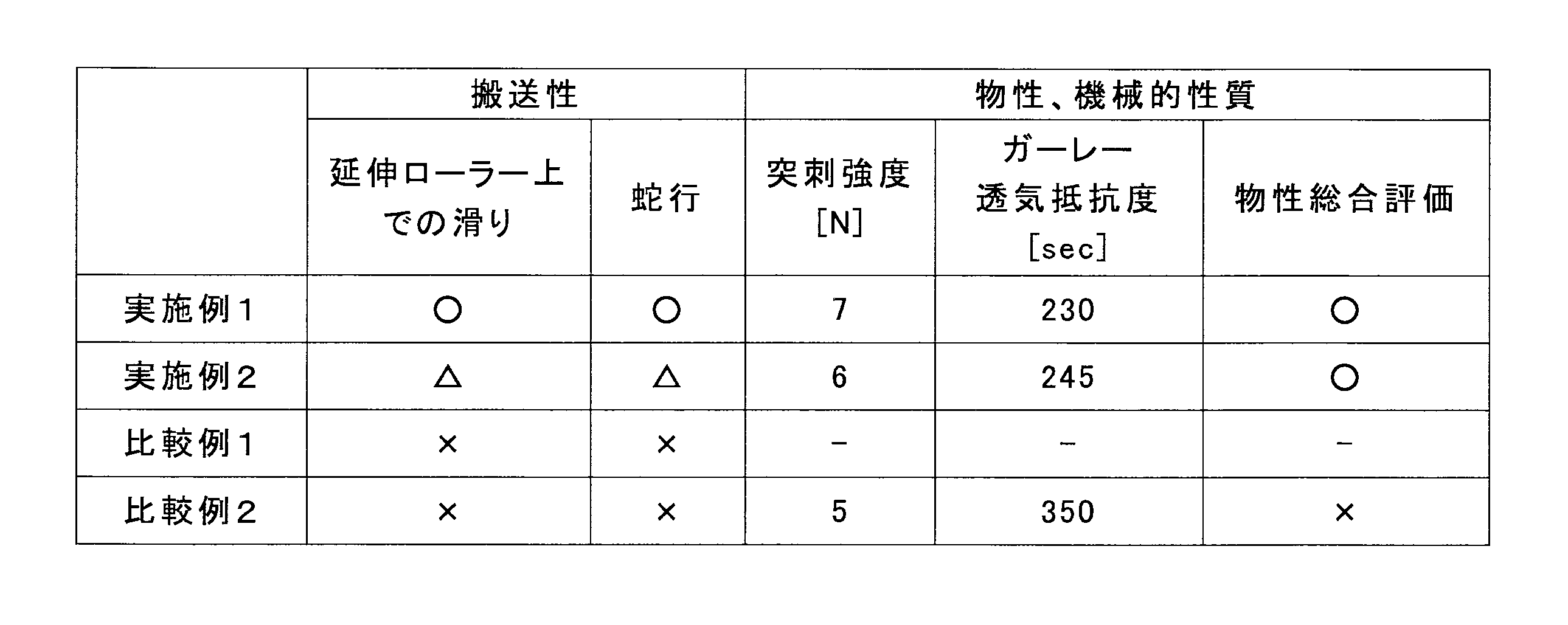
- Example 1 When all Examples and Comparative Examples are compared, in the Examples, there are two or more sections that are stretched between a plurality of rollers, and the magnifications of the plurality of stretching sections are substantially the same. For this reason, generation
- Comparative Example 1 since excessive stretching tension was generated in one stretching section, slipping and meandering could not be prevented, and a microporous plastic film having desired physical properties and mechanical properties could not be obtained. It was.
- a microporous plastic film excellent in strength and physical properties while maintaining running stability under the necessary stretching conditions when performing stretching necessary to obtain various properties of the microporous film. Can be obtained.
- the present invention is not particularly limited, but can be used for microporous plastic films used for separators of electrochemical reactors such as secondary batteries, fuel cells, capacitors, etc., and functions such as filtration membranes, printed membranes and various clothing materials It can be applied to sex web.
- Microporous plastic film 12 Gel-like sheet (film) 13 Uniaxially stretched sheet (film) 14 Biaxially stretched sheet (film) 15 Microporous Plastic Film Roll 21 Extruder 22 Gear Pump 23 Base 31 First Cooling Drum 32 Second Cooling Drum 4 Longitudinal Stretching Process 41 Heating Roller Group 42 Stretching Roller Group 43 Cooling Roller Group 44 Nip Roller 5 Lateral Stretching Process 6 Cleaning and Cleaning Drying process 61 Cleaning solvent 7 Re-stretching heat treatment process 8 Winding process
Abstract
Description
前記延伸を行う前後のローラーへの巻き付け角が実質的に同じであることを特徴とする請求項1に記載の微多孔プラスチックフィルムの製造方法を提供する。
図1は、本発明の一実施形態である微多孔プラスチックフィルムの製造工程の概略側面図である。
ゲル状シート12の厚みは、吐出量に応じた口金スリット部からの流速に対し、冷却ドラムの速度を調整することで調整するのが好ましい。
好ましくは、延伸ローラー群42~横延伸工程5に張力計を設置して実測することで、より高い精度で速比を調整し、張力の釣りあいをとることができる。
[実施例1]
図1の通り、上流側のニップローラー44の本数は、昇温ローラー群41から冷却ローラー分43まで合計10本とした。
[実施例2]
[比較例1]
[比較例2]
[延伸ローラー上での滑り]
×(不可):ローラーとシートの速度差が、ローラー回転速度に対して10%以上
△(可):ローラーとシートの速度差が、ローラー回転速度に対して5%以上10%未満
○(良好):ローラーとシートの速度差が、ローラー回転速度に対して5%未満。
[縦延伸工程の蛇行量]
縦延伸工程4における蛇行量を以下の基準で評価した。
×(不可):蛇行量が10mm以上。
△(可):蛇行量が5mm以上10mm未満。
○(良好):蛇行量が5mm未満。
[微多孔プラスチックフィルム物性および機械的性質]
ガーレー透気抵抗度は、王研式透気抵抗度計(旭精工株式会社製、EGO-1T)を使用して、JIS P8117に準拠して測定した。
○(良好):ガーレー透気抵抗度が230sec±20sec及び突刺強度6N以上
×(不可):上記範囲外

12 ゲル状シート(フィルム)
13 一軸延伸シート(フィルム)
14 二軸延伸シート(フィルム)
15 微多孔プラスチックフィルムロール
21 押出機
22 ギアポンプ
23 口金
31 第1冷却ドラム
32 第2冷却ドラム
4 縦延伸工程
41 昇温ローラー群
42 延伸ローラー群
43 冷却ローラー群
44 ニップローラー
5 横延伸工程
6 洗浄・乾燥工程
61 洗浄溶剤
7 再延伸熱処理工程
8 巻取工程
Claims (5)
- 希釈剤とポリオレフィン樹脂を押出機にて混練し、前記希釈剤が混練された樹脂を口金からシート状に吐出し、前記口金から吐出されたシートをドラム上で冷却固化した後、前記固化したシートを再び加熱して、複数のローラーによりシートの搬送方向に延伸し、前記シートの搬送方向に延伸したシートを冷却した後にシート両端をクリップにて把持してテンターに導入し、その後希釈剤を洗浄する一軸または二軸延伸微多孔プラスチックフィルムの製造方法において、
前記複数のローラーの間にシートを延伸する区間が2つ以上あり、これら複数の延伸区間の延伸倍率が実質的に同じであることを特徴とする、微多孔プラスチックフィルムの製造方法。 - 前記延伸を行う前後のローラーへの巻き付け角が実質的に同じである、請求項1に記載の微多孔プラスチックフィルムの製造方法。
- 請求項1または2に記載の微多孔プラスチックフィルムの製造方法により製造した微多孔プラスチックフィルム。
- 請求項3に記載の微多孔プラスチックフィルムを用いた電池用セパレータ。
- 請求項4に記載の電池用セパレータを用いた電池。
Priority Applications (5)
| Application Number | Priority Date | Filing Date | Title |
|---|---|---|---|
| JP2017500564A JP6757521B2 (ja) | 2015-02-20 | 2016-01-22 | 微多孔プラスチックフィルムの製造方法 |
| CN201680011192.3A CN107405817A (zh) | 2015-02-20 | 2016-01-22 | 微多孔塑料膜的制造方法 |
| EP16752199.6A EP3260269A4 (en) | 2015-02-20 | 2016-01-22 | Method for producing microporous plastic film |
| KR1020177024001A KR20170117442A (ko) | 2015-02-20 | 2016-01-22 | 미다공 플라스틱 필름의 제조 방법 |
| US15/551,876 US20180065289A1 (en) | 2015-02-20 | 2016-01-22 | Method of producing microporous plastic film |
Applications Claiming Priority (2)
| Application Number | Priority Date | Filing Date | Title |
|---|---|---|---|
| JP2015-031392 | 2015-02-20 | ||
| JP2015031392 | 2015-02-20 |
Publications (1)
| Publication Number | Publication Date |
|---|---|
| WO2016132810A1 true WO2016132810A1 (ja) | 2016-08-25 |
Family
ID=56692313
Family Applications (1)
| Application Number | Title | Priority Date | Filing Date |
|---|---|---|---|
| PCT/JP2016/051780 WO2016132810A1 (ja) | 2015-02-20 | 2016-01-22 | 微多孔プラスチックフィルムの製造方法 |
Country Status (6)
| Country | Link |
|---|---|
| US (1) | US20180065289A1 (ja) |
| EP (1) | EP3260269A4 (ja) |
| JP (1) | JP6757521B2 (ja) |
| KR (1) | KR20170117442A (ja) |
| CN (1) | CN107405817A (ja) |
| WO (1) | WO2016132810A1 (ja) |
Cited By (2)
| Publication number | Priority date | Publication date | Assignee | Title |
|---|---|---|---|---|
| JPWO2018043331A1 (ja) * | 2016-08-29 | 2019-06-24 | 東レ株式会社 | 微多孔膜、リチウムイオン二次電池及び微多孔膜製造方法 |
| JP2020164791A (ja) * | 2019-03-26 | 2020-10-08 | 東レ株式会社 | ポリオレフィン微多孔膜およびその製造方法 |
Families Citing this family (3)
| Publication number | Priority date | Publication date | Assignee | Title |
|---|---|---|---|---|
| JP6667353B2 (ja) * | 2016-04-12 | 2020-03-18 | デュプロ精工株式会社 | 湿紙乾燥方法および古紙再生処理装置 |
| CN108656587A (zh) * | 2018-05-30 | 2018-10-16 | 平湖金都电缆材料有限公司 | 一种塑料网状撕裂膜的生产机组 |
| CN109435198B (zh) * | 2018-09-12 | 2021-02-09 | 江苏洁雅家居用品有限公司 | 一种基于保鲜膜的智能生产设备 |
Citations (2)
| Publication number | Priority date | Publication date | Assignee | Title |
|---|---|---|---|---|
| JP2012500130A (ja) * | 2008-08-15 | 2012-01-05 | 東レ東燃機能膜合同会社 | 微多孔膜の製造方法および微多孔膜の製造装置 |
| JP2013234327A (ja) * | 2011-11-29 | 2013-11-21 | Sekisui Chem Co Ltd | プロピレン系樹脂微孔フィルム、電池用セパレータ、電池及びプロピレン系樹脂微孔フィルムの製造方法 |
Family Cites Families (10)
| Publication number | Priority date | Publication date | Assignee | Title |
|---|---|---|---|---|
| JP3351940B2 (ja) * | 1995-09-26 | 2002-12-03 | 東燃化学株式会社 | ポリオレフィン微多孔膜の製造方法 |
| KR100943697B1 (ko) * | 2005-04-06 | 2010-02-23 | 에스케이에너지 주식회사 | 물성, 생산성 및 품질 균일도가 우수한 폴리에틸렌 미세다공막 및 그 제조방법 |
| US20100316902A1 (en) * | 2007-12-31 | 2010-12-16 | Kotaro Takita | Microporous Multilayer Membrane, System And Process For Producing Such Membrane, And The Use Of Such Membrane |
| WO2009084720A1 (en) * | 2007-12-31 | 2009-07-09 | Tonen Chemical Corporation | Microporous multilayer membrane, system and process for producing such membrane, and the use of such membrane |
| JP5366426B2 (ja) * | 2008-04-04 | 2013-12-11 | 東芝機械株式会社 | 多孔性フィルムの製膜方法及び多孔性フィルム製膜用の逐次二軸延伸装置 |
| CN101747549B (zh) * | 2008-12-18 | 2013-06-19 | 比亚迪股份有限公司 | 一种聚烯烃微多孔膜及其制备方法 |
| KR101336593B1 (ko) * | 2010-04-20 | 2013-12-05 | 에스케이이노베이션 주식회사 | 생산성이 우수하며 물성조절이 용이한 폴리올레핀계 미세다공막 제조방법 |
| WO2013100062A1 (ja) * | 2011-12-27 | 2013-07-04 | 東レ株式会社 | 微多孔プラスチックフィルムロールの製造装置及び製造方法 |
| EP3006210B1 (en) * | 2013-05-31 | 2017-11-15 | Toray Industries, Inc. | Multilayer, microporous polyolefin membrane, and production method thereof |
| TWI557165B (zh) * | 2013-10-31 | 2016-11-11 | Lg化學股份有限公司 | 製造電化學裝置用分離器的方法、由該方法製造的電化學裝置用分離器以及包含該分離器的電化學裝置 |
-
2016
- 2016-01-22 US US15/551,876 patent/US20180065289A1/en not_active Abandoned
- 2016-01-22 WO PCT/JP2016/051780 patent/WO2016132810A1/ja active Application Filing
- 2016-01-22 CN CN201680011192.3A patent/CN107405817A/zh active Pending
- 2016-01-22 EP EP16752199.6A patent/EP3260269A4/en not_active Withdrawn
- 2016-01-22 KR KR1020177024001A patent/KR20170117442A/ko unknown
- 2016-01-22 JP JP2017500564A patent/JP6757521B2/ja active Active
Patent Citations (2)
| Publication number | Priority date | Publication date | Assignee | Title |
|---|---|---|---|---|
| JP2012500130A (ja) * | 2008-08-15 | 2012-01-05 | 東レ東燃機能膜合同会社 | 微多孔膜の製造方法および微多孔膜の製造装置 |
| JP2013234327A (ja) * | 2011-11-29 | 2013-11-21 | Sekisui Chem Co Ltd | プロピレン系樹脂微孔フィルム、電池用セパレータ、電池及びプロピレン系樹脂微孔フィルムの製造方法 |
Non-Patent Citations (1)
| Title |
|---|
| See also references of EP3260269A4 * |
Cited By (4)
| Publication number | Priority date | Publication date | Assignee | Title |
|---|---|---|---|---|
| JPWO2018043331A1 (ja) * | 2016-08-29 | 2019-06-24 | 東レ株式会社 | 微多孔膜、リチウムイオン二次電池及び微多孔膜製造方法 |
| JP7047382B2 (ja) | 2016-08-29 | 2022-04-05 | 東レ株式会社 | ポリオレフィン微多孔膜、リチウムイオン二次電池及びポリオレフィン微多孔膜製造方法 |
| JP2020164791A (ja) * | 2019-03-26 | 2020-10-08 | 東レ株式会社 | ポリオレフィン微多孔膜およびその製造方法 |
| JP7470297B2 (ja) | 2019-03-26 | 2024-04-18 | 東レ株式会社 | ポリオレフィン微多孔膜およびその製造方法 |
Also Published As
| Publication number | Publication date |
|---|---|
| JP6757521B2 (ja) | 2020-09-23 |
| EP3260269A1 (en) | 2017-12-27 |
| KR20170117442A (ko) | 2017-10-23 |
| CN107405817A (zh) | 2017-11-28 |
| US20180065289A1 (en) | 2018-03-08 |
| JPWO2016132810A1 (ja) | 2017-12-07 |
| EP3260269A4 (en) | 2018-11-07 |
Similar Documents
| Publication | Publication Date | Title |
|---|---|---|
| WO2016132808A1 (ja) | 微多孔プラスチックフィルムの製造方法 | |
| JP6773022B2 (ja) | 微多孔プラスチックフィルムの製造方法 | |
| JP6555252B2 (ja) | 微多孔プラスチックフィルムの製造方法 | |
| WO2016132810A1 (ja) | 微多孔プラスチックフィルムの製造方法 | |
| CN108370014B (zh) | 聚烯烃微多孔膜、电池用隔膜以及它们的制造方法 | |
| WO2016132809A1 (ja) | 微多孔プラスチックフィルムの製造方法 | |
| WO2016132806A1 (ja) | 微多孔プラスチックフィルムの製造方法 | |
| CN109071864B (zh) | 聚烯烃微多孔膜、电池用隔膜及它们的制造方法 | |
| CN108292726B (zh) | 电池用隔膜及其制造方法 |
Legal Events
| Date | Code | Title | Description |
|---|---|---|---|
| 121 | Ep: the epo has been informed by wipo that ep was designated in this application |
Ref document number: 16752199 Country of ref document: EP Kind code of ref document: A1 |
|
| ENP | Entry into the national phase |
Ref document number: 2017500564 Country of ref document: JP Kind code of ref document: A |
|
| WWE | Wipo information: entry into national phase |
Ref document number: 15551876 Country of ref document: US |
|
| NENP | Non-entry into the national phase |
Ref country code: DE |
|
| REEP | Request for entry into the european phase |
Ref document number: 2016752199 Country of ref document: EP |
|
| ENP | Entry into the national phase |
Ref document number: 20177024001 Country of ref document: KR Kind code of ref document: A |