WO2016132776A1 - パワーステアリング装置 - Google Patents
パワーステアリング装置 Download PDFInfo
- Publication number
- WO2016132776A1 WO2016132776A1 PCT/JP2016/050828 JP2016050828W WO2016132776A1 WO 2016132776 A1 WO2016132776 A1 WO 2016132776A1 JP 2016050828 W JP2016050828 W JP 2016050828W WO 2016132776 A1 WO2016132776 A1 WO 2016132776A1
- Authority
- WO
- WIPO (PCT)
- Prior art keywords
- gear
- steering
- magnetic member
- pole
- power steering
- Prior art date
- Legal status (The legal status is an assumption and is not a legal conclusion. Google has not performed a legal analysis and makes no representation as to the accuracy of the status listed.)
- Ceased
Links
Images





Classifications
-
- B—PERFORMING OPERATIONS; TRANSPORTING
- B62—LAND VEHICLES FOR TRAVELLING OTHERWISE THAN ON RAILS
- B62D—MOTOR VEHICLES; TRAILERS
- B62D15/00—Steering not otherwise provided for
- B62D15/02—Steering position indicators ; Steering position determination; Steering aids
- B62D15/021—Determination of steering angle
- B62D15/0225—Determination of steering angle by measuring on a steering gear element, e.g. on a rack bar
-
- B—PERFORMING OPERATIONS; TRANSPORTING
- B62—LAND VEHICLES FOR TRAVELLING OTHERWISE THAN ON RAILS
- B62D—MOTOR VEHICLES; TRAILERS
- B62D15/00—Steering not otherwise provided for
- B62D15/02—Steering position indicators ; Steering position determination; Steering aids
- B62D15/021—Determination of steering angle
- B62D15/0215—Determination of steering angle by measuring on the steering column
-
- B—PERFORMING OPERATIONS; TRANSPORTING
- B62—LAND VEHICLES FOR TRAVELLING OTHERWISE THAN ON RAILS
- B62D—MOTOR VEHICLES; TRAILERS
- B62D3/00—Steering gears
- B62D3/02—Steering gears mechanical
-
- B—PERFORMING OPERATIONS; TRANSPORTING
- B62—LAND VEHICLES FOR TRAVELLING OTHERWISE THAN ON RAILS
- B62D—MOTOR VEHICLES; TRAILERS
- B62D5/00—Power-assisted or power-driven steering
- B62D5/04—Power-assisted or power-driven steering electrical, e.g. using an electric servo-motor connected to, or forming part of, the steering gear
- B62D5/0421—Electric motor acting on or near steering gear
-
- B—PERFORMING OPERATIONS; TRANSPORTING
- B62—LAND VEHICLES FOR TRAVELLING OTHERWISE THAN ON RAILS
- B62D—MOTOR VEHICLES; TRAILERS
- B62D5/00—Power-assisted or power-driven steering
- B62D5/04—Power-assisted or power-driven steering electrical, e.g. using an electric servo-motor connected to, or forming part of, the steering gear
- B62D5/0457—Power-assisted or power-driven steering electrical, e.g. using an electric servo-motor connected to, or forming part of, the steering gear characterised by control features of the drive means as such
- B62D5/046—Controlling the motor
- B62D5/0463—Controlling the motor calculating assisting torque from the motor based on driver input
-
- B—PERFORMING OPERATIONS; TRANSPORTING
- B62—LAND VEHICLES FOR TRAVELLING OTHERWISE THAN ON RAILS
- B62D—MOTOR VEHICLES; TRAILERS
- B62D6/00—Arrangements for automatically controlling steering depending on driving conditions sensed and responded to, e.g. control circuits
-
- G—PHYSICS
- G01—MEASURING; TESTING
- G01B—MEASURING LENGTH, THICKNESS OR SIMILAR LINEAR DIMENSIONS; MEASURING ANGLES; MEASURING AREAS; MEASURING IRREGULARITIES OF SURFACES OR CONTOURS
- G01B7/00—Measuring arrangements characterised by the use of electric or magnetic techniques
- G01B7/30—Measuring arrangements characterised by the use of electric or magnetic techniques for measuring angles or tapers; for testing the alignment of axes
-
- G—PHYSICS
- G01—MEASURING; TESTING
- G01D—MEASURING NOT SPECIALLY ADAPTED FOR A SPECIFIC VARIABLE; ARRANGEMENTS FOR MEASURING TWO OR MORE VARIABLES NOT COVERED IN A SINGLE OTHER SUBCLASS; TARIFF METERING APPARATUS; MEASURING OR TESTING NOT OTHERWISE PROVIDED FOR
- G01D5/00—Mechanical means for transferring the output of a sensing member; Means for converting the output of a sensing member to another variable where the form or nature of the sensing member does not constrain the means for converting; Transducers not specially adapted for a specific variable
- G01D5/02—Mechanical means for transferring the output of a sensing member; Means for converting the output of a sensing member to another variable where the form or nature of the sensing member does not constrain the means for converting; Transducers not specially adapted for a specific variable using mechanical means
- G01D5/04—Mechanical means for transferring the output of a sensing member; Means for converting the output of a sensing member to another variable where the form or nature of the sensing member does not constrain the means for converting; Transducers not specially adapted for a specific variable using mechanical means using levers; using cams; using gearing
-
- G—PHYSICS
- G01—MEASURING; TESTING
- G01D—MEASURING NOT SPECIALLY ADAPTED FOR A SPECIFIC VARIABLE; ARRANGEMENTS FOR MEASURING TWO OR MORE VARIABLES NOT COVERED IN A SINGLE OTHER SUBCLASS; TARIFF METERING APPARATUS; MEASURING OR TESTING NOT OTHERWISE PROVIDED FOR
- G01D5/00—Mechanical means for transferring the output of a sensing member; Means for converting the output of a sensing member to another variable where the form or nature of the sensing member does not constrain the means for converting; Transducers not specially adapted for a specific variable
- G01D5/12—Mechanical means for transferring the output of a sensing member; Means for converting the output of a sensing member to another variable where the form or nature of the sensing member does not constrain the means for converting; Transducers not specially adapted for a specific variable using electric or magnetic means
- G01D5/14—Mechanical means for transferring the output of a sensing member; Means for converting the output of a sensing member to another variable where the form or nature of the sensing member does not constrain the means for converting; Transducers not specially adapted for a specific variable using electric or magnetic means influencing the magnitude of a current or voltage
- G01D5/142—Mechanical means for transferring the output of a sensing member; Means for converting the output of a sensing member to another variable where the form or nature of the sensing member does not constrain the means for converting; Transducers not specially adapted for a specific variable using electric or magnetic means influencing the magnitude of a current or voltage using Hall-effect devices
- G01D5/145—Mechanical means for transferring the output of a sensing member; Means for converting the output of a sensing member to another variable where the form or nature of the sensing member does not constrain the means for converting; Transducers not specially adapted for a specific variable using electric or magnetic means influencing the magnitude of a current or voltage using Hall-effect devices influenced by the relative movement between the Hall device and magnetic fields
-
- G—PHYSICS
- G01—MEASURING; TESTING
- G01D—MEASURING NOT SPECIALLY ADAPTED FOR A SPECIFIC VARIABLE; ARRANGEMENTS FOR MEASURING TWO OR MORE VARIABLES NOT COVERED IN A SINGLE OTHER SUBCLASS; TARIFF METERING APPARATUS; MEASURING OR TESTING NOT OTHERWISE PROVIDED FOR
- G01D2205/00—Indexing scheme relating to details of means for transferring or converting the output of a sensing member
- G01D2205/20—Detecting rotary movement
- G01D2205/26—Details of encoders or position sensors specially adapted to detect rotation beyond a full turn of 360°, e.g. multi-rotation
Definitions
- the present invention relates to a power steering apparatus that is mounted on an automobile or the like and includes a steering angle sensor that detects a steering angle of a steering wheel.
- Patent Document 1 As a conventional power steering device, one described in Patent Document 1 below is known.
- the power steering apparatus includes a steering mechanism that steers the steered wheels in accordance with the operation of the steering wheel, and an electric motor that applies a steering force to the steering mechanism.
- the power steering device is provided with a steering angle sensor that detects the steering angle of the steering wheel, and the electric motor is controlled based on the steering angle.
- the rudder angle sensor has a magnetic member, has a first gear that rotates as the steering wheel rotates, and also has a magnetic member, rotates in mesh with the first gear, and has the number of teeth. Includes a second gear set to be different from the first gear.
- the rudder angle sensor has two detection elements for detecting the rotation angles (first and second rotation angles) of the first and second gears from the change of the magnetic field of each magnetic member.
- the steering angle (steering absolute angle), which is the amount of rotation from the neutral position of the steering wheel, is detected based on the angle difference between the first and second rotation angles.
- the gears are randomly assembled to the rudder angle sensor without considering the rotation angles.
- the steering absolute angle output by the rudder angle sensor may be shifted by a predetermined angle with respect to the actual steering angle of the steering wheel (actual rudder angle).
- the absolute steering angle is made to coincide with the actual steering angle by calibrating the angle deviation.
- the absolute steering angle detected by the above-described method is based on the premise of calibration, for example, a problem occurs in a nonvolatile memory or the like that stores a correction value related to calibration, and the correction value is referred to. If it becomes impossible, the calculation is performed based on the uncorrected angle difference between the two rotation angles, which may cause a difference from the actual steering angle.
- the present invention has been devised in view of such technical problems, and the first and second gears are assembled to the rudder angle sensor so that the difference between the steering angle and the actual rudder angle is reduced.
- a power steering device that can continue the operation of a steering wheel without obtaining a sense of incongruity even when a malfunction occurs in a calibration value for correcting an output value of an angle sensor.
- the present invention provides a steering mechanism for turning a steered wheel in accordance with an operation of a steering wheel; An electric motor that applies a steering force to the steering mechanism; a sensor housing that is provided in the steering mechanism and includes a first gear support portion and a second gear support portion therein; and the first gear support portion.
- Second magnetic part having N and S poles magnetized around the tooth part and the rotation axis A second gear that rotates in accordance with the rotation of the first gear, and a position of an N pole or S pole that is provided on the second gear and is magnetized on the second magnetic member.
- the first support portion is disposed so as to have a predetermined positional relationship with respect to the first mark portion.
- the first detection element for detecting the rotation angle of the first gear based on the change in the magnetic field generated by the mark portion of 2 and the first magnetic member.
- a steering absolute angle calculating circuit for calculating the absolute angle, based on the steering absolute angle is characterized by comprising a control unit for driving and controlling the electric motor.
- the operation of the steering wheel can be continued without obtaining an uncomfortable feeling of steering.
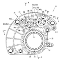
- FIG. 1 is a schematic diagram illustrating an overall configuration of a power steering apparatus according to an embodiment of the present invention. It is a top view which shows the state which removed the cover part and circuit board of the rudder angle sensor which concern on this embodiment.
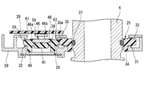
- FIG. 3 is a cross-sectional view taken along line AA of FIG. 2 in a state where a cover part and a circuit board are attached.
- FIG. 3 is a cross-sectional view taken along line BB of FIG. 2 in a state where only a cover portion is attached.
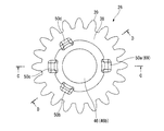
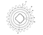
- It is a top view of the gear for the 1st detection used for this embodiment.
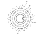
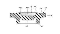
- FIG. 6 is a cross-sectional view taken along the line CC of FIG. It is a rear view of the 1st gear for a detection provided for this embodiment.
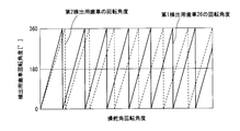
- FIG. 6 is a characteristic diagram illustrating a relationship between a rotation angle of a steering shaft and first and second rotation angles.
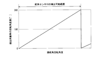
- FIG. 6 is a characteristic diagram illustrating a relationship between a rotation angle of a steering shaft and an angle difference between first and second rotation angles.
- a steering wheel 1 disposed in a passenger compartment and steered wheels 2 and 3 that are front wheels of a vehicle are mechanically connected by a steering mechanism.
- This steering mechanism is connected to the steering wheel 1 through the intermediate shaft 4 and the universal joint 5 so as to be integrally rotatable, and is connected to the steering shaft 6 through a torsion bar (not shown) so that torque can be transmitted.
- a rack bar 8 provided on the outer periphery with a rack 8a that meshes with the pinion 7a on the outer periphery of the pinion shaft 7.
- the pinion shaft 7 and the rack bar 8 constitute a rack and pinion mechanism.
- a steering mechanism is configured.
- the both ends of the rack bar 8 are connected to the steered wheels 2 and 3 via ball joints 9 and 10, tie rods 11 and 12, knuckle arms 13 and 14, respectively.
- a sensor housing 15 is provided in the steering mechanism so as to surround the steering shaft 6 and the pinion shaft 7.
- a torque sensor (not shown) for detecting a steering torque generated in the steering shaft 6 by using a relative rotation angle difference between the steering shaft 6 and the pinion shaft 7 due to torsion of the torsion bar.
- a steering angle sensor 16 that detects a steering angle of the steering shaft 6 is disposed.
- the torque sensor and the steering angle sensor 16 are electrically connected to an ECU 18 that is a control unit via a sensor harness 17.
- the ECU 18 is provided adjacent to the electric motor 19 and has a function of storing and executing various control processes.
- the ECU 18 is provided for steering information such as the steering torque and steering angle, and the steered wheels 2 and 3.
- the electric motor 19 is driven and controlled on the basis of a vehicle speed signal from a vehicle speed sensor provided.
- the electric motor 19 has a pulley 21 fixed to the tip of the output shaft 20, and the pulley 21 is linked to a pulley 22 fixed to the outer periphery of the rack bar 8 via a belt 23.
- a ball screw mechanism (deceleration mechanism) (not shown) is interposed between the pulley 22 and the rack bar 8 so that the rotation of the electric motor 19 is decelerated and the rack bar 8 is linearly moved. It is supposed to be converted.
- the rudder angle sensor 16 includes a case 24 constituting a part of the sensor housing 15 and a main gear 25 connected to the steering shaft 6 so as to be integrally rotatable (in the present invention).
- a first detection gear 26 meshing with the main gear 25 (corresponding to the first gear according to the present invention), and a second detection meshing with the first detection gear 26.
- a gear 27 (corresponding to a second gear according to the present invention), and a circuit board 28 disposed on the upper side of the two detection gears 26 and 27 and outside the case 24.
- the case 24 includes a bottomed cylindrical case body 29 that accommodates the gears 25 to 27, and a plurality of bolts that are not shown in the figure. And a cover portion 30 that closes the upper end opening of the case main body 29 by being coupled.
- the case main body 29 has a cylindrical main gear support portion 31, a first detection gear support portion 32, and a second detection purpose support on which the gears 25 to 27 are rotatably placed and supported while positioning the gears 25 to 27.
- the gear support portions 33 are formed so as to protrude along the axial direction.
- each of the support portions 31 to 33 are formed in a planar shape perpendicular to the axial direction of the steering shaft 6, and the gears 25 to 27 are in a posture parallel to the steering shaft 6. It comes to support.
- the cover portion 30 is formed in a flat plate shape, and has first and second opposing surfaces 30a and 30b facing the first and second detection gears 26 and 27 in the axial direction on the lower surface thereof.
- the main gear 25 is integrally formed of a synthetic resin material in order to reduce weight, reduce meshing noise, and the like, and has a cylindrical base portion 34 and an outer periphery of the base portion 34. And a tooth portion 35 (corresponding to a third tooth portion according to the present invention) formed on the side.
- the base portion 34 has an inner diameter slightly larger than the outer diameter of the steering shaft 6, and the steering shaft 6 is inserted therein with a minute gap.
- An O-ring 36 that is an annular elastic member is interposed between the inner peripheral surface of the base portion 34 and the outer peripheral surface of the steering shaft 6.
- the O-ring 36 is housed and held so as to elastically contact the bottom surface of an annular ring groove 37 formed on the outer peripheral surface of the steering shaft 6, and the outer peripheral side is elastic on the inner peripheral surface on the upper end side of the base portion 34. It touches. Therefore, when the steering shaft 6 rotates, the main gear 25 rotates integrally based on the frictional force of the O-ring 36 elastically mounted between the steering shaft 6 and the base portion 34. Yes.
- the first detection gear 26 is integrally formed of a synthetic resin material. As shown in FIGS. 2 to 7, the disc-shaped base 38 and the teeth of the main gear 25 are provided.
- the tooth part 39 which is the 1st tooth part formed in the outer peripheral side of the said base 38 so that it may mesh with the part 35, and the cylindrical part 40 standingly arranged from the lower end surface of the said base 38 are provided.
- the cylindrical portion 40 is formed coaxially with the base portion 38 and has an outer diameter smaller than the inner diameter of the first detection gear support portion 32, so that the first detection gear support portion 32 Arranged inside.
- a columnar protruding portion 41 is formed so as to protrude from the lower end surface of the base portion 38.
- a fitting recess 41a having a substantially semicircular cross section is formed at a predetermined position in the circumferential direction of the protrusion 41.
- the fitting recess 41a has a function as a gear-side rotation alignment portion when the first detection gear 26 is installed in a first magnetizing device 52 described later.
- the second detection gear 27 is integrally formed of a synthetic resin material. As shown in FIGS. 2 to 4 and 8, the disc-shaped base portion 42 and the base portion 42 are formed. A tooth portion 43 that is a second tooth portion that meshes with the tooth portion 35 of the first detection gear 26, and a cylindrical portion 44 that is erected from the lower end surface of the base portion 42. ing.
- the cylindrical portion 44 is formed in a cylindrical shape coaxial with the base portion 42, and has an outer diameter smaller than the inner diameter of the second detection gear support portion 33, and the second detection gear support portion. 33 is disposed inside.
- a prismatic protrusion 45 projecting from the lower end surface of the base 42 is accommodated and disposed on the inner peripheral side of the cylindrical portion 44.
- a notch-shaped fitting recess 45 a is formed at a predetermined position in the circumferential direction of the protrusion 45.
- the fitting recess 45a has a function as a rotational alignment portion on the gear side when the second detection gear 27 is installed in a second magnetizing device (not shown) to be described later.
- the first detection gear 26 and the second detection gear 27 have teeth of the first detection gear 26 as shown in FIG. 2 in order to obtain a predetermined reduction ratio in which the number of teeth cannot be divided from each other.
- the number of teeth of the portion 39 is set to 20, while the number of teeth of the tooth portion 43 of the second detection gear 27 is set to 22. Accordingly, the base portion 42 and the cylindrical portion 44 of the second detection gear 27 are formed to have a larger diameter than the base portion 38 and the cylindrical portion 40 of the first detection gear 26. .
- the number of teeth of the main gear 25 is set to 40, which is twice the number of teeth 39 of the tooth portion 39 of the first detection gear 26.
- first and second magnets 46 and 47 which are first and second magnetic members, are provided on the upper side of the detection gears 26 and 27, respectively.
- the first and second magnets 46 and 47 are formed in a substantially octagonal shape having a non-circular shape in which the outer peripheral surface is notched in the tangential direction, and the outer peripheral portions 46 a and 47 a Each of the thicknesses is thinner than the inner peripheral portions 46b and 47b.
- the magnets 46 and 47 are arranged so that the upper end surfaces of the inner peripheral portions 46 b and 47 b are exposed from the upper end surfaces of the base portions 38 and 42, respectively.
- the detection gears 26 and 27 are embedded in the detection gears 26 and 27, and the upper end surfaces of the outer peripheral portions 46 a and 47 a are covered with annular protrusions 48 and 49. This is because when the respective detection gears 26 and 27 are molded, so-called insert molding is performed in which the respective magnets 46 and 47 are arranged in a cavity of an injection mold not shown. It is due to that.
- first to fourth recesses 50a to 50d and 51a to 51d that open in the axial direction of the detection gears 26 and 27 are provided on the upper end surfaces of the detection gears 26 and 27, respectively. 46 and 47 are formed so as to surround them.
- the first to fourth recesses 50a to 50d are formed in a substantially rectangular shape in plan view, and have a predetermined size that can be detected by visual recognition or image recognition by a sensor such as a camera.
- a sensor such as a camera.
- the tooth portions 39 of the first detection gear they are arranged on the base 38 side on the inner peripheral side from the tooth bottom of the nearest tooth.
- the first recess 50a is disposed on one radial side of the first detection gear 26, while the second to fourth recesses 50b to 50d other than the first recess 50a are provided for the first detection. It arrange
- the first to fourth recesses 50a to 50d are formed by using four claw portions (not shown) for holding the magnet 46 in the cavity of the injection mold during the insert molding. It is.
- each of the claw portions is formed in a prismatic shape, and grips the outer peripheral surface of the magnet 46 at the center portion instead of the tip portion of the claw at the time of the insert molding, After the injection molding (insert molding) is completed, the first detection gear 26 is extracted.
- the four claw marks formed when the first detection gear 26 is pulled out form the first to fourth recesses 50a to 50d.
- the first to fourth recesses 50a to 50d are configured such that the claw portion grips the outer peripheral surface of the magnet 46 at the center during resin molding. As shown in FIG. 6 and FIG. 6, each depth is larger than the axial width of the outer peripheral surface of the magnet 46.
- the first to fourth recesses 51a to 51d formed in the second detection gear 27 are also formed in a predetermined size that can be visually recognized by a camera, a sensor, or the like, and the second detection.
- Each tooth portion 43 of the gear 27 is provided on the base 42 side on the inner peripheral side from the tooth bottom of the nearest tooth.
- the first recess 51a is disposed on one radial side of the second detection gear 27, while the second to fourth recesses 51b to 51d other than the first recess 51a are used for the second detection. It arrange
- each of the recesses 51 a to 51 d has a depth larger than the axial width of the outer peripheral surface of the magnet 47.
- the magnets 46 and 47 are not magnetized at the time of the insert molding described above, and are magnetized by the magnetizing device after the detection gears 26 and 27 are molded.
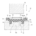
- the magnetizing device 52 that magnetizes the first magnet 46 of the first detection gear 26 includes a first holding base 54 that holds the first detection gear 26, and the first detection gear. And a magnetizing coil 55 that magnetizes the magnet 46 by a magnetic field generated in the axial direction of the gear 26.
- the upper surface 54a of the upper end portion of the first holding stand 54 is formed flat, and a cylindrical holding hole 56 is recessed inside the upper end portion.
- the holding hole 56 is set to have a diameter slightly larger than the outer diameter of the cylindrical portion 40 of the first detection gear 26 and smaller than the outer diameter of the cylindrical portion 44 of the second detection gear 27. Has been. Therefore, the first holding base 54 can insert the cylindrical portion 40 of the first detection gear 26 into the holding hole 56, while the cylindrical portion 44 of the second detection gear 27 is It cannot be inserted.
- the holding hole 56 is formed such that the depth to the bottom surface 56 a is larger than the vertical width of the cylindrical portion 40 of the first detection gear 26, and substantially the entire cylindrical portion 40 is the holding hole 56.
- the upper surface 54a around the holding hole 56 supports the lower end surface of the base portion 38 of the first detection gear 26 when it is inserted to a position (hereinafter referred to as a maximum insertion position) accommodated in the inside of the first detection gear 26.
- a maximum insertion position accommodated in the inside of the first detection gear 26.
- a cylindrical fitting convex portion 57 which is a rotational alignment portion on the first magnetizing device 52 side is provided on the bottom surface 56a of the holding hole 56 so as to protrude upward.
- the fitting convex portion 57 is formed in a circular cross section substantially the same as the cross sectional shape of the fitting concave portion 41a of the first detection gear 26, and
- the first detection gear 26 is disposed at a position displaced from the central axis of the holding hole 56 by the same distance as the distance from the central axis of the first detection gear 26 to the fitting recess 41a.
- the fitting convex portion 57 has an axial length extending to a predetermined length substantially the same as the depth of the holding hole 56. For this reason, when the relative rotation position of the fitting convex portion 57 with respect to the fitting concave portion 41a does not match, the cylindrical portion 40 cannot be inserted to the maximum insertion position by hitting the lower surface of the protruding portion 41. On the other hand, when the relative rotation position with respect to the fitting recess 41a is correct, the cylindrical portion 40 can be inserted up to the maximum insertion position. That is, the fitting convex portion 57 has a function as a rotational alignment portion on the magnetizing device 52 side that determines a rotational position when the first detection gear 26 is installed on the first holding base 54. Yes.
- the magnetized coil 55 is formed in a substantially cylindrical shape by winding a lead wire (not shown), and is disposed at a position where the axial center of the holding hole 56 is the same. Has been.
- the magnetizing coil 55 is formed to be movable along the axial direction, and in the state where the first detection gear 26 is held in the holding hole 56, the magnetized coil 55 is close to the first detection gear 26. By doing so, the exposed upper surface of the inner peripheral portion 46b of the magnet 46 is magnetized (surface magnetized).
- the second magnetizing device that magnetizes the second detection gear 27 also includes a second holding base that holds the second detection gear 27 and an axis of the second detection gear 27. And a magnetizing coil 55 that magnetizes the magnet 47 with a magnetic field generated in a direction.
- the second holding table will be described, but the same configuration as the first holding table 54 will be omitted, and only the differences will be described.
- the second holding base is formed so that the diameter of the holding hole is slightly larger than the cylindrical portion 44 of the second detecting gear 27 in view of installing the second detecting gear 27.
- the fitting convex portion 58 protruding from the bottom surface of the holding hole of the second holding base crosses in accordance with the shape of the fitting concave portion 45a of the second detection gear 27, as shown by a one-dot chain line in FIG. Even if an attempt is made to install the first detection gear 26 on the second holding table, it cannot be installed because the shape of the fitting portion is different, and erroneous installation can be avoided.
- N and S poles are formed in the magnets 46 and 47 as shown in FIG.
- an S pole is formed on the lower surface (on the opposite side in the axial direction) of the region where the N pole is formed on the upper surfaces of the magnets 46 and 47.
- An N pole is formed on the lower surface of the region where the S pole is formed on the upper surface.
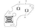
- the circuit board 28 has first and second MR elements (magnetoresistive elements) 59 as first and second detection elements so as to face the magnets 46 and 47 on the back side. , 60 are provided.
- Each of the MR elements 59, 60 detects a change in the magnetic field generated by the opposing magnets 46, 47 as a change in the resistance value of the resistance element, thereby rotating the corresponding rotation angle of each of the detection gears 26, 27. The first rotation angle and the second rotation angle are detected.
- each of the MR elements 59 and 60 provided on the outer side of the sensor housing 15 is provided on the cover portion 30 constituting a part of the sensor housing 15.
- Two first and second through holes 61 and 62 are formed so as not to interfere with 30.
- First and second projecting portions 63 and 64 are formed so as to project toward 27.
- the first protrusion 63 is positioned between the tooth portion 35 of the first detection gear 26 and a first recess 50a (a first mark portion 69 described later) in the radial direction of the first detection gear 26.
- the second projecting portion 64 is formed in the radial direction of the second detection gear 27 with a tooth portion 39 of the second detection gear 27 and a first recess 51a (a first recess 51a described later). 2 mark part 70).
- the first and second projecting portions 63 and 64 are extended so that the tip surfaces 63a and 64a are slightly separated from the upper end surfaces of the corresponding detection gears 26 and 27, respectively. When the detection gears 26 and 27 are tilted or fall down, they come into contact with the detection gears 26 and 27.
- the first and second rotation angles detected by the MR elements 59 and 60 are transmitted to the microprocessor 65 provided in the ECU 18 via the sensor harness 17. .
- the microprocessor 65 is electrically connected to a nonvolatile memory (not shown), and the first and second MR elements 59, 59 stored in the storage circuit 66 of the nonvolatile memory.
- the correction value for correcting the output of 60 can be referred to.
- the correction value is the output value of the first and second MR elements 59 and 60, that is, the first and second MR elements 59 and 60, so that the angle difference between the first and second rotation angles is 180 ° when the steering wheel 1 is in the neutral position.
- the first and second rotation angles are calibrated and are uniquely determined when the first and second detection gears 26 and 27 are assembled to the rudder angle sensor 16.
- the microprocessor 65 also includes a correction value abnormality detection circuit 67 that detects abnormality of the correction value, and a neutral position that is a rotational position of the steering wheel 1 when the steered wheels 2 and 3 are directed straight.
- a steering absolute angle calculating circuit 68 for calculating a steering angle (steering absolute angle) of the steering wheel 1.
- the correction value abnormality detection circuit 67 is set so as to detect an abnormality when the correction value fluctuates using the fact that the correction value is a uniquely determined numerical value that does not fluctuate.
- the steering absolute angle calculation circuit 68 refers to the correction value and the first and second rotation angles when the correction value abnormality detection circuit 67 does not detect abnormality of the correction value.
- the correction value abnormality detection circuit 67 detects the abnormality of the correction value, the correction value is not referred to and only the first and second rotation angles are referred to.
- the steering absolute angle calculation circuit 68 calculates an angle difference of the second rotation angle with respect to the first rotation angle from the first and second rotation angles referred to, and calculates the steering absolute angle based on the angle difference. Calculate.
- the first and second rotation angles are reset to zero each time the detection gears 26 and 27 are rotated once, respectively, but the number of teeth of the detection gears 26 and 27 is set.
- the angle difference between the first rotation angle and the second rotation angle resulting from the difference there is always only one set with respect to the rotation angle of the steering shaft 6 as shown in FIG.
- the steering absolute angle calculation circuit 68 obtains the steering absolute angle from the angle difference by utilizing this structural characteristic.
- the steering absolute angle calculation circuit 68 determines that the neutral position is when the corrected first and second rotation angle is 180 ° when the correction value is normal. When an abnormality occurs in the correction value, a position where the angle difference between the uncorrected first and second rotation angles is 180 ° is determined as a neutral position. And the said steering absolute angle is calculated based on the fluctuation
- the first and second detection gears 26 and 27 are first and second detected parts that indicate that the magnetic poles of the magnets 46 and 47 are assembled in a predetermined positional relationship with each other. Certain first and second mark portions 69 and 70 are provided, respectively.
- the first detection gear 26 and the first detection gear 26 are arranged so that the first recess 50a of the first detection gear 26 and the first recess 51a of the second detection gear 27 face each other. 2
- the magnetic pole of the magnet 46 and the magnetic pole of the magnet 47 can be in a predetermined positional relationship.
- the main gear 25 is provided with third mark portions 71 and 71 for displaying the rotational position of the steering wheel 1. As shown in FIG. 2, each of the third mark portions 71, 71 is formed in a concave shape by cutting out a part of the upper end portion of the base portion 34 of the main gear 25 along the axial direction. Positioning of the relative angle between the main gear 25 and the steering shaft 6 is performed by the third mark portions 71 and 71.
- gears 25 to 27 are arranged on the gear support portions 31 to 33 so that the mark portions 69 to 71 are in a positional relationship as shown in FIG. 2 when the rudder angle sensor 16 is assembled. Has been.
- the main gear 25 has the third mark portions 71 and 71 arranged in the vertical direction in FIG. 2, and the detection gears 26 and 27 have the first and second mark portions. 69 and 70 are arranged so as to face each other. [Effects of this embodiment] Therefore, in this power steering apparatus, when the driver rotates the steering wheel 1, the steering angle sensor 16 calculates the steering angle of the steering shaft 6 that rotates together with the steering wheel 1. The ECU 18 drives and controls the electric motor 19 based on this calculation result, so that a steering assist force corresponding to the actual steering situation is sent to the steering mechanism.
- the steering angle sensor 16 calculates the steering absolute angle according to the actual steering angle based on the first and second rotation angles corrected by the calibration function.
- the steering absolute angle close to the actual steering angle can be calculated.
- the correction value abnormality detection circuit 67 detects the abnormality, and in response to this, the steering absolute angle calculation circuit 68 does not refer to the correction value.
- the calculation is based on the uncorrected first and second rotation angles.
- the steering absolute angle calculation circuit 68 calculates the steering absolute angle close to the actual steering angle, the neutral position indicated by the steering angle sensor 16 and the actual position are corrected even if correction is not performed. It is necessary to reduce the difference between the steering wheel 1 and the neutral position.
- the first and second detection gears 26 and 27 are provided with the first and second mark portions 69 and 70, respectively, and the steering wheel 1 is in the neutral position.
- the first and second detection gears 26 and 27 are arranged so that the first and second mark portions 69 and 70 face each other.
- the driver can operate the steering wheel 1 without obtaining a great sense of discomfort.
- the main gear 25 is provided with third mark portions 71 and 71 indicating the neutral position of the steering wheel 1, and the first to third mark portions are respectively provided.
- the gears 25 to 27 are arranged so that the portions 69 to 71 have a predetermined positional relationship.
- the steering absolute angle calculation circuit 68 when the correction value abnormality detection circuit 67 detects an abnormality of the correction value, the steering absolute angle calculation circuit 68 does not refer to the correction value that has become an abnormal value. As a result, it is possible to prevent the steering absolute angle calculated by the steering absolute angle calculation circuit 68 from becoming an abnormal value, thereby ensuring continuity of safe operation.
- the steering absolute angle is calculated using the microprocessor 65 in the ECU 18 that drives and controls the electric motor 19, the steering angle sensor 16 is provided inside the sensor housing 15 (case 24). Compared with a case where a dedicated microprocessor is separately provided, the apparatus can be simplified and downsized.
- the magnets 46 and 47 are embedded in the first and second detection gears 26 and 27 by insert molding, and then magnetized by the magnetizing coils 55 and 55, respectively.
- the first and second mark portions 69 and 70 showing the magnetic poles and the actual magnets 46 and 70 are compared with the case where a pre-magnetized magnet is embedded in the first and second detection gears 26 and 27. Since it becomes difficult for the shift
- the magnets 46 and 47 are formed in a disc shape, and surface magnetization is adopted as a magnetizing method for the magnets 46 and 47.
- the upper end surfaces of the magnets 46 and 47 exposed from the detection gears 26 and 27 are magnetized, so that the MR elements 59 and 60 can easily detect the first and second rotation angles. Can be done.
- the concave portions 50a to 50d and 51a to 51d are formed on the inner peripheral side of the tooth bases of the nearest teeth among the tooth portions 35 and 39 of the detection gears 26 and 27, respectively. Arranged on the 34,38 side. Therefore, even if resin shrinkage occurs around the recesses 50a to 50d and 51a to 51d due to the formation of the recesses 50a to 50d and 51a to 51d during resin molding, The influence hardly affects the tooth portions 35 and 39. Thereby, it is possible to suppress a change in shape and a decrease in strength of the tooth portions 35 and 39 when the first and second mark portions 69 and 70 are formed on the detection gears 26 and 27.
- the orthogonal cross-sectional shape of each of the magnets 46 and 47 with respect to the axial direction of the corresponding gears 26 and 27 is formed in a substantially octagonal shape that is a non-circular shape. The rotation inside the detection gears 26 and 27 is restricted.
- the positions of the protrusions 63 and 64 are set between the mark portions 69 and 70 of the corresponding gears 26 and 27 and the tooth portions 35 and 39, the inclination of the gears 26 and 27 is suppressed. In doing so, it is difficult for the protrusions 63 and 64 to interfere with the tooth portions 35 and 39 and the mark portions 69 and 70.
- first and second mark portions 69 and 70 are formed in a concave shape that opens along the axial direction of each of the gears 26 and 27, the circuit board is compared with the case where a convex mark portion is provided. 28, the cover 30 and the like can be prevented from being damaged.
- the first and second mark portions 69 and 70 the first recesses 50a and 51a, which are claw marks of the claw portions that sandwiched the magnets 46 and 47 at the time of insert molding, are used. As compared with the case where the first and second mark portions 69 and 70 are newly provided, the apparatus can be simplified.
- first and second mark portions 69, 70 are formed to have a depth greater than the axial width of the outer peripheral surface of each of the magnets 46, 47, respectively. Since the detection performance of 70 is improved, it can be easily recognized by visual observation, a camera, a sensor, or the like. Thereby, workability
- prescribed positional relationship can be improved.
- the fitting concave portion 41a of the first detection gear 26 and the fitting convex portion 57 of the first magnetizing device 52 are fitted to each other.
- the relative rotational positions of the first detection gear 26 and the first magnetizing device 52 are matched, and the cylindrical portion 40 of the first detection gear 26 and the holding hole 56 of the first holding base 54 are fitted to each other.
- the axial center positions of the first detection gear 26 and the first magnetizing device 52 are matched.
- the magnet 46 can be magnetized in a state in which the relative rotation position and the axial center position of the magnet 46 are aligned, so that the first mark portion 69 indicating the position of the magnetic pole is actually The deviation from the magnetic poles of the respective magnets 46 is further reduced. As a result, it is possible to more reliably suppress the deviation between the steering absolute angle and the actual steering angle during assembly.
- the first detection gear 26 is formed such that the diameter of the cylindrical portion 40 and the shape of the fitting recess 41a are different from those of the second detection gear 27, and the first The magnetizing device 52 is formed in a shape that matches the first detection gear 26 so that the second detection gear 27 cannot be incorporated therein. As a result, it is possible to suppress a mistake in the magnetizing operation such as installing the second detection gear 27 with respect to the first magnetizing device 52.
- the second detection gear 27 and a second magnetization device are also formed so as to correspond to the relationship between the first detection gear 26 and the first magnetization device 52 described above. Therefore, the same effect can be obtained between them.
- the second to fourth recesses 50b to 50d which may be mistaken for the first and second mark portions 69 and 70, around the first and second mark portions 69 and 70. Since 51b to 51d are not provided, each of the first to fourth recesses 50a to 50d and 51a to 51d is recognized when the first and second mark portions 69 and 70 are recognized by a camera or a sensor. Among them, it is possible to set a recognition condition such that a portion where no other recess exists in the vicinity is recognized as the first and second mark portions 69 and 70 (respective first recesses 50a and 51a).
- the camera, the sensor, or the like does not need to measure the entire upper end surface of each of the rotating detection gears 26 and 27, but has a partial range as shown by a two-dot chain line in FIG. It is possible to recognize the first and second mark portions 69 and 70 by measuring only this. Thereby, even if a camera or a sensor having a low resolution (resolution) is used, the first and second mark portions 69 and 70 can be recognized without any problem.
- the annular protrusions 48 and 49 for restricting the lifting of the magnets 46 and 47 are provided. Omission of the magnets 46 and 47 from the detection gears 26 and 27 is suppressed.
- the positional relationship between the mark portions 69 and 70 in the initial state where the detection gears 26 and 27 are accommodated in the detection gear support portions 32 and 33 is not limited to the facing state as in the present embodiment.
- the state in which the mark portions 69 and 70 are spaced apart from each other may be set as the correct positional relationship.
- the alignment of the steering absolute angle and the actual steering angle is ensured by the combined use of the alignment of the first and second mark portions 69 and 70 and the calibration. If there is no problem in the operation, the storage circuit 66 relating to calibration, the correction value abnormality detection circuit 67 and the like are abolished, and the actual steering angle is obtained only by aligning the first and second mark portions 69 and 70. A match may be made.
- the ECU 18 having the microprocessor 65, the electric motor 19 or the like is used for the correction value calculation and recalculation.
- the operation must be performed in a state where all the components are assembled, and the work is complicated. Such a problem can be fundamentally solved.
- the second detection gear 27 is directly driven to rotate by the first detection gear 26 when the tooth portion 39 and the tooth portion 35 of the first detection gear 26 are engaged with each other.
- the first detection gear 26 may be rotationally driven indirectly by interposing another gear with the first detection gear 26.
- first detection gear 26 rotates with the rotation of the steering wheel 1 due to the main gear 25 being interposed.
- main gear 25 is eliminated and the first detection gear 26 is detected on the steering shaft 6. It is also possible to configure so as to rotate integrally with the steering wheel 1 by attaching the gear 26 for use.
- first and second detected parts have been described as the first and second mark parts 69 and 70 that can be visually recognized and image recognized by a sensor such as a camera.
- the detection unit displays the positions of the magnetic poles of the magnets 46 and 47 provided on the detection gears 26 and 27, and can detect or recognize the position as long as the position can be detected by a predetermined detection device. You can't do it.
- a method may be employed in which magnetic members other than the magnets 46 and 47 are embedded in the first and second detection gears 26 and 27 and the positions of these magnetic members are detected by a magnetic sensor.
- the assembly of the gears 26 and 27 to the rudder angle sensor 16 is performed by a machine tool that is driven based on position information acquired from the detection device.
- the following modes can be considered.
- the power steering device is provided in a steering mechanism that steers the steered wheels in accordance with the operation of the steering wheel, an electric motor that applies a steering force to the steering mechanism, and the steering mechanism.
- a sensor housing having one gear support portion and a second gear support portion, and a plurality of first teeth integrally held on the outer peripheral side while being rotatably held by the first gear support portion
- a first gear member having a north pole and a south pole magnetized around the center and the rotation axis, and a first gear that rotates as the steering wheel rotates, and the first gear.
- the first mark member indicating the position of the N pole or S pole magnetized on the first magnetic member, and the second gear support portion are rotatably held on the outer peripheral side.
- a combination of a second detection element to be detected, a rotation angle of the first gear, and a rotation angle of the second gear Accordingly, a steering absolute angle calculation circuit that calculates a steering absolute angle of the steering wheel from a neutral position of the steering wheel when the steered wheel is directed straight, and the electric motor is driven based on the steering absolute angle.
- control unit includes a microprocessor, and the steering absolute angle calculation circuit is provided in the microprocessor.
- the first gear and the second gear are in a mold cavity and the magnetic member of the first gear and the second gear.
- the first magnetic member is magnetized by a magnetic field generated in the axial direction of the first gear after the insert molding
- the first magnetic member is magnetized by the magnetic field generated in the axial direction of the first gear after the insert molding
- the second magnetic member is magnetized by a magnetic field generated in the axial direction of the second gear after the insert molding.
- the first magnetic member is formed so that a cross-sectional shape orthogonal to the axial direction of the first gear is non-circular
- the second magnetic member is formed so that the cross-sectional shape orthogonal to the axial direction of the second gear is non-circular.
- the first mark portion is a tooth bottom of a tooth closest to the first mark portion among the plurality of first tooth portions.
- the second mark portion is provided closer to the inner periphery than the tooth bottom of the tooth closest to the second mark portion among the plurality of second tooth portions.
- the sensor housing is provided with a first facing surface provided so as to face the first gear in the axial direction of the first gear.
- a first protrusion provided on the first facing surface and formed to protrude toward the first gear, and the second gear in the axial direction of the second gear.
- a second opposing surface provided so as to oppose, and a second protrusion provided on the second opposing surface and projecting toward the second gear side.
- the first protrusion is formed so as to be positioned between the plurality of first teeth and the first mark portion in the radial direction of the first gear, and the second protrusion Is a plurality of tooth portions of the second gear in the radial direction of the second gear. It is formed so as to be located between the second mark portion.
- the first mark portion is formed in a concave shape so as to open in the axial direction of the first gear, and the second mark portion. Is formed in a concave shape so as to open in the axial direction of the second gear.
- the first gear and the second gear are the first magnetic member and the second magnetic member in a cavity of a mold.
- the first magnetic member is held in the cavity in a state where the outer peripheral surface is sandwiched between the claw portions of the insert molding equipment.
- the first mark portion is formed by extracting the claw portion of the insert molding facility from the first gear after the insert molding, and the second magnetic member has an outer peripheral surface of the insert molding facility.
- the second mark part is held in the cavity in a state of being sandwiched by the claw part, and the claw part of the insert molding equipment is the second tooth after the insert molding. It is formed by being extracted from.
- the first mark portion has a depth in the axial direction of the first gear that is an axis of the outer peripheral surface of the first magnetic member.
- the second mark portion is formed so as to be larger than the width in the direction, and the depth in the axial direction of the second gear is larger than the width in the axial direction of the outer peripheral surface of the second magnetic member. Is formed.
- the first gear has the first mark portion on one axial side and the first gear on the other axial side.
- a first rotational alignment unit that aligns a relative rotational position with a device for magnetizing the magnetic member is provided, and the second gear has the first mark portion on one side in the axial direction and the axial direction.
- On the other side there is provided a second rotational alignment unit that aligns the relative rotational position with the device for magnetizing the second magnetic member.
- one of the first gear and the second gear is formed to have a smaller diameter than the other,
- the first rotational alignment portion or the second rotational alignment portion is formed so that it cannot be installed in a device for magnetizing the magnetic member of the other gear.
- the first gear includes a first cylindrical portion centered on a rotation axis of the first gear, and the first magnetic part.
- the member is magnetized in a state in which the first cylindrical portion is inserted into a recess of a magnetizing device formed to engage with the first cylindrical portion, and the second gear is A second cylindrical portion centered on the rotation axis of the second gear, and the second magnetic member is disposed in a recess of a magnetizing device formed to engage with the second cylindrical portion. Magnetization is performed with the two cylindrical portions inserted.
- the first gear includes only the first mark portion as a mark in a predetermined range including the first mark portion in the circumferential direction.
- the second gear is formed with only the second mark portion as a mark in a predetermined range including the second mark portion in the circumferential direction.
- the steering mechanism has a third gear provided in the sensor housing, and the steering mechanism has a steering shaft that rotates as the steering wheel rotates.
- the third gear is provided on the outer peripheral side with an insertion hole through which the steering shaft is inserted, and is engaged with the plurality of first teeth to rotate the steering wheel.
- a plurality of third tooth portions that are transmitted to the center and a third mark portion provided at a predetermined position in the circumferential direction, the first gear, the second gear, and the third gear. are assembled to the sensor housing such that the first mark portion, the second mark portion, and the third mark portion are in a predetermined positional relationship.
- the power steering apparatus in a steering mechanism that steers the steered wheels in accordance with an operation of the steering wheel, an electric motor that applies a steering force to the steering mechanism, and the steering mechanism.
- a sensor housing having a first gear support portion and a second gear support portion, and a plurality of first housings that are rotatably held by the first gear support portion and are integrally formed on the outer peripheral side.
- a first gear member having a north pole and a south pole magnetized around a tooth portion and a rotation axis, the first gear rotating with the rotation of the steering wheel, and the first gear; And a first detected portion that can detect the position of the N pole or S pole magnetized on the first magnetic member by a detection device, and the second gear support portion.
- a detection device detects a position of a second gear that rotates with the rotation of the first gear, and an N pole or S pole that is provided on the second gear and is magnetized on the second magnetic member. And is arranged so as to have a predetermined positional relationship with respect to the first detected portion in an initial state in which the first gear and the second gear are accommodated in each gear support portion.
- a first detection element for detecting a rotation angle of the first gear based on a change in a magnetic field generated by the second detected portion and the first magnetic member, and a magnetic field generated by the second magnetic member.
- a second detection element for detecting a rotation angle of the second gear based on the change of the first gear; and Steering absolute angle calculation for calculating a steering absolute angle of the steering wheel from a neutral position of the steering wheel when the steered wheel is directed straight by a combination of the rotation angle of the gear and the rotation angle of the second gear A circuit, and a control unit that drives and controls the electric motor based on the steering absolute angle.
- the power steering device is provided in a steering mechanism that steers the steered wheels in accordance with the operation of the steering wheel, an electric motor that applies a steering force to the steering mechanism, and the steering mechanism.
- a sensor housing having a first gear support portion and a second gear support portion, and a plurality of first housings that are rotatably held by the first gear support portion and integrally formed on the outer peripheral side.
- a first gear member having a north pole and a south pole magnetized around a tooth portion and a rotation shaft of the first gear, and rotating with the rotation of the steering wheel; and the second gear support Centered on a plurality of second teeth and a rotation shaft that are integrally formed so as to be directly or indirectly engaged with the plurality of first teeth on the outer peripheral side.
- N pole and S pole are magnetized A rotation angle of the first gear based on a change in the magnetic field generated by the second gear and the second gear rotating with the rotation of the first gear.
- a first detection element that detects the rotation angle of the second gear based on a change in the magnetic field generated by the second magnetic member, and an output of the first detection element Or a storage circuit that stores a correction value for correcting the output of the second detection element, a correction value abnormality detection circuit that detects abnormality of the correction value, and when the abnormality of the correction value is not detected, Based on the output of the first detection element, the output of the second detection element, and the correction value, the steering wheel steering absolute angle from the neutral position of the steering wheel when the steered wheel is directed straight ahead Steering absolute angle calculation circuit A control unit that drives and controls the electric motor based on the steering absolute angle, and the first gear and the second gear are connected to the magnetic pole direction of the first magnetic member and the second gear.
- the steering absolute angle calculation circuit is arranged on the first gear support part so that the direction of the magnetic pole of the magnetic member has a predetermined positional relationship. Based on the output of the first detection element and the output of the second detection element, the absolute steering angle was set to be calculated.
- the first gear includes a first mark portion that displays a position of an N pole or an S pole magnetized on the first magnetic member, and the second gear. Includes a second mark portion for displaying the position of the N pole or S pole magnetized on the second magnetic member.
- control unit includes a microprocessor, and the steering absolute angle calculation circuit is provided in the microprocessor.
- the first gear and the second gear are disposed in a cavity of a mold and the magnetic member of the first gear and the second gear. Formed by insert molding that performs injection molding in a state in which each of the magnetic members of the gear is disposed, the first magnetic member is magnetized by a magnetic field generated in the axial direction of the first gear after the insert molding, The second magnetic member is magnetized by a magnetic field generated in the axial direction of the second gear after the insert molding.
- the first mark portion is a tooth bottom of a tooth closest to the first mark portion among the plurality of first tooth portions.
- the second mark portion is provided closer to the inner periphery than the tooth bottom of the tooth closest to the second mark portion among the plurality of second tooth portions.
Landscapes
- Engineering & Computer Science (AREA)
- Chemical & Material Sciences (AREA)
- Combustion & Propulsion (AREA)
- Transportation (AREA)
- Mechanical Engineering (AREA)
- Physics & Mathematics (AREA)
- General Physics & Mathematics (AREA)
- Measurement Of Length, Angles, Or The Like Using Electric Or Magnetic Means (AREA)
- Power Steering Mechanism (AREA)
Abstract
Description
該操舵機構に操舵力を付与する電動モータと、前記操舵機構に設けられ、内部に第1の歯車支持部及び第2の歯車支持部を備えたセンサハウジングと、前記第1の歯車支持部に回転自在に保持されていると共に、外周側に一体に形成された複数の第1の歯部及び回転軸を中心としてN極及びS極が着磁された第1の磁性部材を有し、前記ステアリングホイールの回転に伴って回転する第1の歯車と、該第1の歯車に設けられ、前記第1の磁性部材に着磁されたN極またはS極の位置を表示する第1の目印部と、前記第2の歯車支持部に回転自在に保持されていると共に、外周側に前記複数の第1の歯部と直接的または間接的に噛み合うように一体に形成された複数の第2の歯部及び回転軸を中心としてN極及びS極が着磁された第2の磁性部材を有し、前記第1の歯車の回転に伴って回転する第2の歯車と、該第2の歯車に設けられ、前記第2の磁性部材に着磁されたN極またはS極の位置を表示すると共に、前記各歯車支持部に前記第1の歯車と前記第2の歯車が収容された初期状態において、前記第1の目印部に対して所定の位置関係となるように配置された第2の目印部と、前記第1の磁性部材が発する磁界の変化に基づき、前記第1の歯車の回転角を検出する第1の検出素子と、前記第2の磁性部材が発する磁界の変化に基づき、前記第2の歯車の回転角を検出する第2の検出素子と、前記第1の歯車の回転角と前記第2の歯車の回転角との組み合せによって、前記転舵輪が直進方向を向くときの前記ステアリングホイールの中立位置からの前記ステアリングホイールの操舵絶対角を演算する操舵絶対角演算回路と、前記操舵絶対角に基づき、前記電動モータを駆動制御する制御部と、を備えたことを特徴としている。
〔本実施形態の作用効果〕
したがって、このパワーステアリング装置では、運転者が前記ステアリングホイール1を回動させると、前記舵角センサ16が前記ステアリングホイール1と一体に回転する前記操舵軸6の操舵角の演算を行った後に、この演算結果に基づいて前記ECU18が前記電動モータ19を駆動制御することで、実際の操舵状況に見合った操舵アシスト力が操舵機構へ送られることとなる。
Claims (20)
- ステアリングホイールの操作に伴い転舵輪を転舵させる操舵機構と、
該操舵機構に操舵力を付与する電動モータと、
前記操舵機構に設けられ、内部に第1の歯車支持部及び第2の歯車支持部を備えたセンサハウジングと、
前記第1の歯車支持部に回転自在に保持されていると共に、外周側に一体に形成された複数の第1の歯部及び回転軸を中心としてN極及びS極が着磁された第1の磁性部材を有し、前記ステアリングホイールの回転に伴って回転する第1の歯車と、
該第1の歯車に設けられ、前記第1の磁性部材に着磁されたN極またはS極の位置を表示する第1の目印部と、
前記第2の歯車支持部に回転自在に保持されていると共に、外周側に前記複数の第1の歯部と直接的または間接的に噛み合うように一体に形成された複数の第2の歯部及び回転軸を中心としてN極及びS極が着磁された第2の磁性部材を有し、前記第1の歯車の回転に伴って回転する第2の歯車と、
該第2の歯車に設けられ、前記第2の磁性部材に着磁されたN極またはS極の位置を表示すると共に、前記各歯車支持部に前記第1の歯車と前記第2の歯車が収容された初期状態において、前記第1の目印部に対して所定の位置関係となるように配置された第2の目印部と、
前記第1の磁性部材が発する磁界の変化に基づき、前記第1の歯車の回転角を検出する第1の検出素子と、
前記第2の磁性部材が発する磁界の変化に基づき、前記第2の歯車の回転角を検出する第2の検出素子と、
前記第1の歯車の回転角と前記第2の歯車の回転角との組み合せによって、前記転舵輪が直進方向を向くときの前記ステアリングホイールの中立位置からの前記ステアリングホイールの操舵絶対角を演算する操舵絶対角演算回路と、
前記操舵絶対角に基づき、前記電動モータを駆動制御する制御部と、
を備えたことを特徴とするパワーステアリング装置。 - 請求項1に記載のパワーステアリング装置において、
前記制御部は、マイクロプロセッサを備え、
前記操舵絶対角演算回路は、前記マイクロプロセッサ内に設けられることを特徴とするパワーステアリング装置。 - 請求項1に記載のパワーステアリング装置において、
前記第1の歯車及び前記第2の歯車は、金型のキャビティ内に前記第1の歯車の磁性部材及び前記第2の歯車の磁性部材のそれぞれを配置した状態で射出成形を行うインサート成形によって形成され、
前記第1の磁性部材は、前記インサート成形後に前記第1の歯車の軸方向へ発生する磁界により着磁され、
前記第2の磁性部材は、前記インサート成形後に前記第2の歯車の軸方向へ発生する磁界により着磁されることを特徴とするパワーステアリング装置。 - 請求項3に記載のパワーステアリング装置において、
前記第1の磁性部材は、前記第1の歯車の軸方向に対する直交断面形状が非円形となるように形成され、
前記第2の磁性部材は、前記第2の歯車の軸方向に対する直交断面形状が非円形となるように形成されることを特徴とするパワーステアリング装置。 - 請求項1に記載のパワーステアリング装置において、
前記第1の目印部は、前記複数の第1の歯部のうち、前記第1の目印部に最も近い歯の歯底よりも内周側に設けられ、
前記第2の目印部は、前記複数の第2の歯部のうち、前記第2の目印部に最も近い歯の歯底よりも内周側に設けられることを特徴とするパワーステアリング装置。 - 請求項5に記載のパワーステアリング装置において、
前記センサハウジングは、前記第1の歯車の軸方向において前記第1の歯車と対向するように設けられた第1の対向面と、該第1の対向面に設けられ、前記第1の歯車側に向かって突出するように形成された第1の突起部と、前記第2の歯車の軸方向において前記第2の歯車と対向するように設けられた第2の対向面と、該第2の対向面に設けられ、前記第2の歯車側に向かって突出するように形成された第2の突起部と、を有し、
前記第1の突起部は、前記第1の歯車の径方向において前記複数の第1の歯部と前記第1の目印部との間に位置するように形成され、
前記第2の突起部は、前記第2の歯車の径方向において前記第2の歯車の複数の歯部と前記第2の目印部との間に位置するように形成されることを特徴とするパワーステアリング装置。 - 請求項1に記載のパワーステアリング装置において、
前記第1の目印部は、前記第1の歯車の軸方向へ開口するように凹状に形成され、
前記第2の目印部は、前記第2の歯車の軸方向へ開口するように凹状に形成されることを特徴とするパワーステアリング装置。 - 請求項7に記載のパワーステアリング装置において、
前記第1の歯車及び前記第2の歯車は、金型のキャビティ内に前記第1の磁性部材及び前記第2の磁性部材のそれぞれを配置した状態で射出成形を行うインサート成形によって形成され、
前記第1の磁性部材は、外周面をインサート成形用の設備の爪部で挟持された状態で前記キャビティ内に保持され、
前記第1の目印部は、インサート成形後に前記インサート成形用の設備の爪部が前記第1の歯車から抜き取られることによって形成され、
前記第2の磁性部材は、外周面をインサート成形用の設備の爪部で挟持された状態で前記キャビティ内に保持され、
前記第2の目印部は、インサート成形後に前記インサート成形用の設備の爪部が前記第2の歯車から抜き取られることによって形成されることを特徴とするパワーステアリング装置。 - 請求項8に記載のパワーステアリング装置において、
前記第1の目印部は、前記第1の歯車の軸方向における深さが、前記第1の磁性部材の外周面の軸方向巾よりも大きくなるように形成され、
前記第2の目印部は、前記第2の歯車の軸方向における深さが、前記第2の磁性部材の外周面の軸方向巾よりも大きくなるように形成されることを特徴とするパワーステアリング装置。 - 請求項1に記載のパワーステアリング装置において、
前記第1の歯車は、軸方向一方側に前記第1の目印部を有すると共に、軸方向他方側に、前記第1の磁性部材を着磁するための装置との相対回転位置を合わせる第1の回転位置合わせ部を備え、
前記第2の歯車は、軸方向一方側に前記第1の目印部を有すると共に、軸方向他方側に、前記第2の磁性部材を着磁するための装置との相対回転位置を合わせる第2の回転位置合わせ部を備えることを特徴とするパワーステアリング装置。 - 請求項10に記載のパワーステアリング装置において、
前記第1の歯車と前記第2の歯車のいずれか一方は、他方に対し直径が小さくなるように形成されると共に、前記他方の歯車の磁性部材を着磁するための装置に設置できないように前記第1の回転位置合わせ部または前記第2の回転位置合わせ部が形成されることを特徴とするパワーステアリング装置。 - 請求項10に記載のパワーステアリング装置において、
前記第1の歯車は、該第1の歯車の回転軸を中心とした第1の円筒部を備え、
前記第1の磁性部材は、前記第1の円筒部と係合するように形成された着磁装置の凹部内に前記第1の円筒部が挿入された状態で着磁され、
前記第2の歯車は、該第2の歯車の回転軸を中心とした第2の円筒部を備え、
前記第2の磁性部材は、前記第2の円筒部と係合するように形成された着磁装置の凹部内に前記第2の円筒部が挿入された状態で着磁されることを特徴とするパワーステアリング装置。 - 請求項1に記載のパワーステアリング装置において、
前記第1の歯車は、円周方向の前記第1の目印部を含む所定範囲において目印として前記第1の目印部のみが形成され、
前記第2の歯車は、円周方向の前記第2の目印部を含む所定範囲において目印として前記第2の目印部のみが形成されることを特徴とするパワーステアリング装置。 - 請求項1に記載のパワーステアリング装置は、前記センサハウジングに設けられた第3の歯車を有し、
前記操舵機構は、前記ステアリングホイールの回転に伴い回転する操舵軸を備え、
前記第3の歯車は、内部に前記操舵軸を挿通させる挿通孔と、外周側に設けられ、前記複数の第1の歯部と噛み合うことにより前記ステアリングホイールの回転を前記第1の歯車に伝達する複数の第3の歯部と、円周方向の所定位置に設けられた第3の目印部と、を備え、
前記第1の歯車と、前記第2の歯車及び前記第3の歯車は、前記第1の目印部と、前記第2の目印部及び前記第3の目印部が、それぞれ所定の位置関係となるように前記センサハウジングへ組み付けられることを特徴とするパワーステアリング装置。 - ステアリングホイールの操作に伴い転舵輪を転舵させる操舵機構と、
該操舵機構に操舵力を付与する電動モータと、
前記操舵機構に設けられ、内部に第1の歯車支持部及び第2の歯車支持部を備えたセンサハウジングと、
前記第1の歯車支持部に回転自在に保持されていると共に、外周側に一体に形成された複数の第1の歯部及び回転軸を中心としてN極及びS極が着磁された第1の磁性部材を有し、前記ステアリングホイールの回転に伴って回転する第1の歯車と、
該第1の歯車に設けられ、前記第1の磁性部材に着磁されたN極またはS極の位置を検出装置によって検出可能とする第1の被検出部と、
前記第2の歯車支持部に回転自在に保持されていると共に、外周側に前記複数の第1の歯部と直接的または間接的に噛み合うように一体に形成された複数の第2の歯部及び回転軸を中心としてN極及びS極が着磁された第2の磁性部材を有し、前記第1の歯車の回転に伴って回転する第2の歯車と、
該第2の歯車に設けられ、前記第2の磁性部材に着磁されたN極またはS極の位置を検出装置によって検出可能とすると共に、前記各歯車支持部に前記第1の歯車と前記第2の歯車が収容された初期状態において、前記第1の被検出部に対して所定の位置関係となるように配置された第2の被検出部と、
前記第1の磁性部材が発する磁界の変化に基づき、前記第1の歯車の回転角を検出する第1の検出素子と、
前記第2の磁性部材が発する磁界の変化に基づき、前記第2の歯車の回転角を検出する第2の検出素子と、
前記第1の歯車の回転角と前記第2の歯車の回転角との組み合せによって、前記転舵輪が直進方向を向くときの前記ステアリングホイールの中立位置からの前記ステアリングホイールの操舵絶対角を演算する操舵絶対角演算回路と、
前記操舵絶対角に基づき、前記電動モータを駆動制御する制御部と、
を備えたことを特徴とするパワーステアリング装置。 - ステアリングホイールの操作に伴い転舵輪を転舵させる操舵機構と、
該操舵機構に操舵力を付与する電動モータと、
前記操舵機構に設けられ、内部に第1の歯車支持部及び第2の歯車支持部を備えたセンサハウジングと、
前記第1の歯車支持部に回転自在に保持されていると共に、外周側に一体に形成された複数の第1の歯部及び回転軸を中心としてN極及びS極が着磁された第1の磁性部材を有し、前記ステアリングホイールの回転に伴って回転する第1の歯車と、
前記第2の歯車支持部に回転自在に保持されていると共に、外周側に前記複数の第1の歯部と直接的または間接的に噛み合うように一体に形成された複数の第2の歯部及び回転軸を中心としてN極及びS極が着磁された第2の磁性部材を有し、前記第1の歯車の回転に伴って回転する第2の歯車と、
前記第1の磁性部材が発する磁界の変化に基づき、前記第1の歯車の回転角を検出する第1の検出素子と、
前記第2の磁性部材が発する磁界の変化に基づき、前記第2の歯車の回転角を検出する第2の検出素子と、
前記第1の検出素子の出力または前記第2の検出素子の出力を補正するための補正値を記憶する記憶回路と、
前記補正値の異常を検出する補正値異常検出回路と、
前記補正値の異常が検出されない場合に、前記第1の検出素子の出力と、前記第2の検出素子の出力、及び前記補正値に基づき、前記転舵輪が直進方向を向くときの前記ステアリングホイールの中立位置からの前記ステアリングホイールの操舵絶対角を演算する操舵絶対角演算回路と、
前記操舵絶対角に基づき、前記電動モータを駆動制御する制御部と、
を備え、
前記第1の歯車及び前記第2の歯車を、前記第1の磁性部材の磁極の方向と前記第2の磁性部材の磁極の方向とが所定の位置関係となるように、前記各歯車支持部へ配置すると共に、
前記補正値異常検出回路が異常を検出した場合には、操舵絶対角演算回路が前記第1の検出素子の出力及び前記第2の検出素子の出力に基づき、前記操舵絶対角を演算するように設定したことを特徴とするパワーステアリング装置。 - 請求項16に記載のパワーステアリング装置において、
前記第1の歯車は、前記第1の磁性部材に着磁されたN極またはS極の位置を表示する第1の目印部を備え、
前記第2の歯車は、前記第2の磁性部材に着磁されたN極またはS極の位置を表示する第2の目印部を備えることを特徴とするパワーステアリング装置。 - 請求項17に記載のパワーステアリング装置において、
前記制御部は、マイクロプロセッサを備え、
前記操舵絶対角演算回路は、前記マイクロプロセッサ内に設けられることを特徴とするパワーステアリング装置。 - 請求項16に記載のパワーステアリング装置において、
前記第1の歯車及び前記第2の歯車は、金型のキャビティ内に前記第1の歯車の磁性部材及び前記第2の歯車の磁性部材のそれぞれを配置した状態で射出成形を行うインサート成形によって形成され、
前記第1の磁性部材は、前記インサート成形後に前記第1の歯車の軸方向へ発生する磁界により着磁され、
前記第2の磁性部材は、前記インサート成形後に前記第2の歯車の軸方向へ発生する磁界により着磁されることを特徴とするパワーステアリング装置。 - 請求項16に記載のパワーステアリング装置において、
前記第1の目印部は、前記複数の第1の歯部のうち、前記第1の目印部に最も近い歯の歯底よりも内周側に設けられ、
前記第2の目印部は、前記複数の第2の歯部のうち、前記第2の目印部に最も近い歯の歯底よりも内周側に設けられることを特徴とするパワーステアリング装置。
Priority Applications (5)
| Application Number | Priority Date | Filing Date | Title |
|---|---|---|---|
| CN201680005347.2A CN107207037B (zh) | 2015-02-18 | 2016-01-13 | 动力转向装置 |
| JP2017500547A JP6317027B2 (ja) | 2015-02-18 | 2016-01-13 | パワーステアリング装置 |
| KR1020177022032A KR20170103892A (ko) | 2015-02-18 | 2016-01-13 | 파워 스티어링 장치 |
| DE112016000797.3T DE112016000797B4 (de) | 2015-02-18 | 2016-01-13 | Servolenkungsvorrichtung |
| US15/546,779 US10589782B2 (en) | 2015-02-18 | 2016-01-13 | Power steering apparatus |
Applications Claiming Priority (2)
| Application Number | Priority Date | Filing Date | Title |
|---|---|---|---|
| JP2015-029193 | 2015-02-18 | ||
| JP2015029193 | 2015-02-18 |
Publications (1)
| Publication Number | Publication Date |
|---|---|
| WO2016132776A1 true WO2016132776A1 (ja) | 2016-08-25 |
Family
ID=56692361
Family Applications (1)
| Application Number | Title | Priority Date | Filing Date |
|---|---|---|---|
| PCT/JP2016/050828 Ceased WO2016132776A1 (ja) | 2015-02-18 | 2016-01-13 | パワーステアリング装置 |
Country Status (6)
| Country | Link |
|---|---|
| US (1) | US10589782B2 (ja) |
| JP (1) | JP6317027B2 (ja) |
| KR (1) | KR20170103892A (ja) |
| CN (1) | CN107207037B (ja) |
| DE (1) | DE112016000797B4 (ja) |
| WO (1) | WO2016132776A1 (ja) |
Cited By (5)
| Publication number | Priority date | Publication date | Assignee | Title |
|---|---|---|---|---|
| CN109689474A (zh) * | 2016-09-20 | 2019-04-26 | 日立汽车系统株式会社 | 转向装置 |
| JP2020148595A (ja) * | 2019-03-13 | 2020-09-17 | 株式会社ジェイテクト | 回転角度検出装置用検出ギヤ、及び回転角度検出装置、並びに回転角度検出装置用検出ギヤの製造方法 |
| JP2022114175A (ja) * | 2021-01-26 | 2022-08-05 | 日立Astemo株式会社 | 操舵装置 |
| US11639192B2 (en) * | 2019-03-28 | 2023-05-02 | Denso Corporation | Detection unit |
| JP2023082269A (ja) * | 2021-12-02 | 2023-06-14 | セイコーエプソン株式会社 | エンコーダー、駆動装置、及びエンコーダーの組立方法 |
Families Citing this family (11)
| Publication number | Priority date | Publication date | Assignee | Title |
|---|---|---|---|---|
| US10933907B2 (en) * | 2016-09-20 | 2021-03-02 | Hitachi Automotive Systems, Ltd. | Sensor device |
| DE102017004672A1 (de) | 2017-05-16 | 2018-11-22 | Hengstler Gmbh | Multiturn-Winkelmessgerät |
| DE102018117155A1 (de) * | 2018-07-16 | 2020-01-16 | Trw Automotive Gmbh | Lenkungsunterstützungsvorrichtung |
| DE102020108860A1 (de) | 2020-03-31 | 2021-09-30 | Minebea Mitsumi Inc. | Vorrichtung und Verfahren zur Positionsbestimmung bei einem Elektromotor |
| JP7487995B2 (ja) * | 2020-04-24 | 2024-05-21 | 株式会社Subaru | 操舵角検出装置 |
| DE102020131667A1 (de) * | 2020-11-30 | 2022-06-02 | Minebea Mitsumi Inc. | Anordnung mit einem um eine Drehachse drehbaren Bauteil für einen Stellantrieb und einem an dem drehbaren Bauteil befestigten Sensorelement |
| DE102021104487A1 (de) * | 2021-02-25 | 2022-08-25 | Robert Bosch Gesellschaft mit beschränkter Haftung | Verfahren zum Betrieb eines Fahrzeugs und Fahrzeug |
| DE102023203408A1 (de) * | 2023-04-14 | 2024-10-17 | Zf Automotive Germany Gmbh | Lenksystem für ein Fahrzeug mit einem Lenkelement und Steer-by-Wire-Lenkung mit einem solchen Lenksystem |
| US12674688B2 (en) * | 2023-04-28 | 2026-07-07 | Proterial, Ltd. | Position detection device |
| KR20260058356A (ko) * | 2024-10-22 | 2026-04-29 | 엘지이노텍 주식회사 | 비정상 각도검출부의 보완이 가능한 앵글센서 |
| KR20260092030A (ko) * | 2024-12-11 | 2026-06-18 | 엘지이노텍 주식회사 | 차량용 조향 센서 |
Citations (4)
| Publication number | Priority date | Publication date | Assignee | Title |
|---|---|---|---|---|
| JPS6378754U (ja) * | 1986-11-13 | 1988-05-25 | ||
| JP2011252840A (ja) * | 2010-06-03 | 2011-12-15 | Tokai Rika Co Ltd | 回転角度検出装置の初期設定方法 |
| JP2013156184A (ja) * | 2012-01-31 | 2013-08-15 | Panasonic Corp | 回転角度検出装置 |
| JP2014019264A (ja) * | 2012-07-17 | 2014-02-03 | Hitachi Automotive Systems Steering Ltd | パワーステアリング装置 |
Family Cites Families (16)
| Publication number | Priority date | Publication date | Assignee | Title |
|---|---|---|---|---|
| JPS61174687A (ja) * | 1985-01-29 | 1986-08-06 | Furukawa Electric Co Ltd:The | 面発光型半導体レ−ザ |
| JP2003344100A (ja) | 2002-05-28 | 2003-12-03 | Niles Co Ltd | 回転検出装置及びその製造方法 |
| KR100856749B1 (ko) * | 2006-11-15 | 2008-09-05 | 대성전기공업 주식회사 | 차량용 조향휠 각도 감지장치 |
| CN101629623B (zh) * | 2009-08-04 | 2011-03-16 | 中国科学院电工研究所 | 永磁齿轮的阻尼系统 |
| JP5097800B2 (ja) * | 2010-06-09 | 2012-12-12 | アルプス電気株式会社 | 回転角センサ |
| DE102010033769A1 (de) * | 2010-08-09 | 2012-02-09 | Valeo Schalter Und Sensoren Gmbh | Vorrichtung mit einem Drehmomentsensor und einem Drehwinkelsensor |
| PL2609399T3 (pl) * | 2010-08-24 | 2019-02-28 | Rotork Controls Limited | Urządzenie przystosowane do zapewniania wskazania położenia kątowego dla wejściowego członu na wielu obrotach |
| DE102010063845A1 (de) * | 2010-12-22 | 2012-06-28 | Robert Bosch Gmbh | Winkelsensor, Zahnrad für Winkelsensor und Verfahren zum Herstellen eines solchen Zahnrades |
| JP5793106B2 (ja) * | 2012-04-26 | 2015-10-14 | 日立オートモティブシステムズステアリング株式会社 | パワーステアリング装置およびパワーステアリング装置の制御装置 |
| JP5893498B2 (ja) * | 2012-04-26 | 2016-03-23 | 日立オートモティブシステムズステアリング株式会社 | パワーステアリング装置およびパワーステアリング装置の制御装置 |
| DE102012109787B4 (de) | 2012-10-15 | 2014-05-15 | Takata AG | Lenkwinkelsensor für Kraftfahrzeuge |
| CN104067461B (zh) * | 2013-01-15 | 2016-06-22 | 古河电气工业株式会社 | 内置有传感器的旋转连接器 |
| JP5969407B2 (ja) * | 2013-01-30 | 2016-08-17 | 日立オートモティブシステムズ株式会社 | 操舵角センサ |
| CN103072622A (zh) * | 2013-02-27 | 2013-05-01 | 湖南时代卓越汽车电子技术有限公司 | 方向盘转向角度传感器装置 |
| JP6007131B2 (ja) | 2013-03-01 | 2016-10-12 | 日立オートモティブシステムズ株式会社 | 操舵角センサおよびこれを用いた電動パワーステアリング装置 |
| JP6140537B2 (ja) * | 2013-06-12 | 2017-05-31 | 日本電産サンキョー株式会社 | モータ |
-
2016
- 2016-01-13 DE DE112016000797.3T patent/DE112016000797B4/de active Active
- 2016-01-13 KR KR1020177022032A patent/KR20170103892A/ko not_active Ceased
- 2016-01-13 US US15/546,779 patent/US10589782B2/en active Active
- 2016-01-13 JP JP2017500547A patent/JP6317027B2/ja active Active
- 2016-01-13 WO PCT/JP2016/050828 patent/WO2016132776A1/ja not_active Ceased
- 2016-01-13 CN CN201680005347.2A patent/CN107207037B/zh active Active
Patent Citations (4)
| Publication number | Priority date | Publication date | Assignee | Title |
|---|---|---|---|---|
| JPS6378754U (ja) * | 1986-11-13 | 1988-05-25 | ||
| JP2011252840A (ja) * | 2010-06-03 | 2011-12-15 | Tokai Rika Co Ltd | 回転角度検出装置の初期設定方法 |
| JP2013156184A (ja) * | 2012-01-31 | 2013-08-15 | Panasonic Corp | 回転角度検出装置 |
| JP2014019264A (ja) * | 2012-07-17 | 2014-02-03 | Hitachi Automotive Systems Steering Ltd | パワーステアリング装置 |
Cited By (7)
| Publication number | Priority date | Publication date | Assignee | Title |
|---|---|---|---|---|
| CN109689474A (zh) * | 2016-09-20 | 2019-04-26 | 日立汽车系统株式会社 | 转向装置 |
| JP2020148595A (ja) * | 2019-03-13 | 2020-09-17 | 株式会社ジェイテクト | 回転角度検出装置用検出ギヤ、及び回転角度検出装置、並びに回転角度検出装置用検出ギヤの製造方法 |
| JP7218627B2 (ja) | 2019-03-13 | 2023-02-07 | 株式会社ジェイテクト | 回転角度検出装置用検出ギヤ、及び回転角度検出装置、並びに回転角度検出装置用検出ギヤの製造方法 |
| US11639192B2 (en) * | 2019-03-28 | 2023-05-02 | Denso Corporation | Detection unit |
| JP2022114175A (ja) * | 2021-01-26 | 2022-08-05 | 日立Astemo株式会社 | 操舵装置 |
| JP7485621B2 (ja) | 2021-01-26 | 2024-05-16 | 日立Astemo株式会社 | 操舵装置 |
| JP2023082269A (ja) * | 2021-12-02 | 2023-06-14 | セイコーエプソン株式会社 | エンコーダー、駆動装置、及びエンコーダーの組立方法 |
Also Published As
| Publication number | Publication date |
|---|---|
| KR20170103892A (ko) | 2017-09-13 |
| DE112016000797B4 (de) | 2025-04-17 |
| CN107207037B (zh) | 2019-08-30 |
| JP6317027B2 (ja) | 2018-04-25 |
| CN107207037A (zh) | 2017-09-26 |
| JPWO2016132776A1 (ja) | 2017-09-21 |
| US20180009476A1 (en) | 2018-01-11 |
| DE112016000797T5 (de) | 2017-10-26 |
| US10589782B2 (en) | 2020-03-17 |
Similar Documents
| Publication | Publication Date | Title |
|---|---|---|
| JP6317027B2 (ja) | パワーステアリング装置 | |
| JP5680962B2 (ja) | 軸貫通非接触の多回転絶対位置磁気センサ | |
| EP3423333B1 (en) | Ripple minimization by proper as/ts magnet arrangement in electric power assisted steering apparatus | |
| US9212892B2 (en) | Steering angle sensor | |
| JP4027339B2 (ja) | 電動パワーステアリング装置 | |
| CN106794867A (zh) | 电动助力转向系统 | |
| US20130113471A1 (en) | Rotation angle detection device and torque sensor | |
| US20110303001A1 (en) | Rotary angle and rotary torque sensing device | |
| JP2008241411A (ja) | 舵角検出装置 | |
| US9057652B2 (en) | Torque detecting apparatus | |
| CN106660576A (zh) | 电动助力转向系统 | |
| US8510962B2 (en) | Angle sensor | |
| JP5871151B2 (ja) | ヨーク組立体の製造方法 | |
| EP2456067B1 (en) | Diagnostic system and method for an electric power steering system | |
| JP6160298B2 (ja) | トルク検出装置、このトルク検出装置を備える電動パワーステアリング装置、および、トルク検出装置の校正方法 | |
| KR20120133404A (ko) | 토크앵글센서 | |
| JP5447319B2 (ja) | 車両用指示計器 | |
| JP5950459B2 (ja) | パワーステアリング装置 | |
| US20230408247A1 (en) | Rotation angle detection device | |
| KR20150018282A (ko) | 토크앵글센서 | |
| KR20150041274A (ko) | 전동식 조향장치의 페일 세이프 방법 | |
| JP7155602B2 (ja) | 演算装置 | |
| JP2009092463A (ja) | トルク検出装置、電動パワーステアリング装置、およびトルク検出装置の製造方法 | |
| KR101694718B1 (ko) | 조향각 제어장치 | |
| JP2015121475A (ja) | 磁気ヨークアセンブリの取り付け方法および磁気ヨークアセンブリ |
Legal Events
| Date | Code | Title | Description |
|---|---|---|---|
| 121 | Ep: the epo has been informed by wipo that ep was designated in this application |
Ref document number: 16752165 Country of ref document: EP Kind code of ref document: A1 |
|
| ENP | Entry into the national phase |
Ref document number: 2017500547 Country of ref document: JP Kind code of ref document: A |
|
| WWE | Wipo information: entry into national phase |
Ref document number: 15546779 Country of ref document: US |
|
| ENP | Entry into the national phase |
Ref document number: 20177022032 Country of ref document: KR Kind code of ref document: A |
|
| WWE | Wipo information: entry into national phase |
Ref document number: 112016000797 Country of ref document: DE |
|
| 122 | Ep: pct application non-entry in european phase |
Ref document number: 16752165 Country of ref document: EP Kind code of ref document: A1 |
|
| WWG | Wipo information: grant in national office |
Ref document number: 112016000797 Country of ref document: DE |