WO2016132573A1 - ドライ真空ポンプ装置およびその制御方法 - Google Patents
ドライ真空ポンプ装置およびその制御方法 Download PDFInfo
- Publication number
- WO2016132573A1 WO2016132573A1 PCT/JP2015/071321 JP2015071321W WO2016132573A1 WO 2016132573 A1 WO2016132573 A1 WO 2016132573A1 JP 2015071321 W JP2015071321 W JP 2015071321W WO 2016132573 A1 WO2016132573 A1 WO 2016132573A1
- Authority
- WO
- WIPO (PCT)
- Prior art keywords
- inverter
- power
- vacuum pump
- motor
- dry vacuum
- Prior art date
- Legal status (The legal status is an assumption and is not a legal conclusion. Google has not performed a legal analysis and makes no representation as to the accuracy of the status listed.)
- Ceased
Links
Images
Classifications
-
- H—ELECTRICITY
- H02—GENERATION; CONVERSION OR DISTRIBUTION OF ELECTRIC POWER
- H02P—CONTROL OR REGULATION OF ELECTRIC MOTORS, ELECTRIC GENERATORS OR DYNAMO-ELECTRIC CONVERTERS; CONTROLLING TRANSFORMERS, REACTORS OR CHOKE COILS
- H02P23/00—Arrangements or methods for the control of AC motors characterised by a control method other than vector control
-
- H—ELECTRICITY
- H02—GENERATION; CONVERSION OR DISTRIBUTION OF ELECTRIC POWER
- H02P—CONTROL OR REGULATION OF ELECTRIC MOTORS, ELECTRIC GENERATORS OR DYNAMO-ELECTRIC CONVERTERS; CONTROLLING TRANSFORMERS, REACTORS OR CHOKE COILS
- H02P27/00—Arrangements or methods for the control of AC motors characterised by the kind of supply voltage
- H02P27/04—Arrangements or methods for the control of AC motors characterised by the kind of supply voltage using variable-frequency supply voltage, e.g. inverter or converter supply voltage
- H02P27/06—Arrangements or methods for the control of AC motors characterised by the kind of supply voltage using variable-frequency supply voltage, e.g. inverter or converter supply voltage using DC to AC converters or inverters
Definitions
- the present invention relates to a dry vacuum pump device and a control method therefor, and particularly a dry vacuum that can immediately restart rotation of a vacuum pump after a power failure such as “instantaneous power failure”, which indicates a power failure that occurs in a short time of about 1 second or less.
- the present invention relates to a pump device and a control method thereof.
- a dry vacuum pump device In a production line for semiconductor devices, liquid crystals, solar panels, LEDs, etc., a dry vacuum pump device is widely used to evacuate the inside of a chamber in which various processes are performed.
- a power failure such as “instantaneous power failure”, which indicates a power failure that occurs in a short time of about 1 second or less
- the internal pressure of the chamber realized by exhausting the vacuum pump increases.
- the process conditions in the chamber change, the manufacturing process cannot be continued and the production line is stopped.
- the longer the pump operation control stop time of the dry vacuum pump device due to a power failure the more serious damage is caused. Therefore, it is desirable to restart the dry vacuum pump device immediately after power recovery.
- a dry vacuum pump device includes a dry vacuum pump, a motor that drives the dry vacuum pump, an inverter that controls the rotational speed (rotational frequency) of the motor, and a control device that controls the operation of the inverter.
- the operation speed of the dry vacuum pump is controlled by supplying AC power of variable frequency to the motor.
- the power supply from the inverter apparatus to the vacuum pump drive motor is stopped due to a power failure, so that the operation of the vacuum pump is stopped and the pump drive motor is decelerated.
- the output control of the inverter device recovers immediately after the input power is restored.
- a large regenerative power is generated as if the motor itself is a generator that supplies power to the inverter output terminal side.
- this regenerative power is generated at the inverter output terminal, when viewed as an inverter, the inverter itself controls the regenerative power from the motor superimposed on the power that should be supplied to the motor. It will control beyond the normal use area. For this reason, since the switching element in the inverter may be supplied with electric power / current exceeding the normal use, there is a possibility of causing a failure when regenerative power is generated.
- a regenerative resistor for regenerative power consumption is provided, and the regenerative power is dissipated without using a regenerative resistor.
- a method of performing control to return to the power supply side (input side) or a method of spontaneously attenuating regenerative power from motor deceleration without returning to inverter control until the motor reaches a predetermined rotational speed or less is proposed.
- the pump / motor is kept below a predetermined rotational speed so that regenerative power does not return to the inverter side at the time of a power failure. Until then, the inverter control does not return, the regenerative power is naturally consumed by the motor deceleration, and the dry vacuum pump is restarted after the pump / motor is below a predetermined number of revolutions.
- the SEMI standard established as an industry standard for semiconductor manufacturing equipment has provisions for instantaneous power outages and normal operation when a power outage occurs within 1 second. There is a need for quick pump rotation recovery during continuation and power recovery. Therefore, in a dry vacuum pump for a semiconductor manufacturing apparatus, a control method for returning the pump motor after a power failure occurs and power recovery is a major issue.
- the present inventors supply power to the inverter immediately when power is restored within a short time within 1 second while consuming regenerative power generated on the motor side at the time of a power failure by the power device of the inverter. This is an investigation of measures to restart the pump.
- the present invention has been made in view of the above circumstances, and enables regenerative power generated on the motor side at the time of a power failure to be consumed by the power device of the inverter while supplying power from the power source to the inverter immediately after power recovery. It is an object of the present invention to provide a dry vacuum pump device and a control method thereof that can restart the vacuum pump immediately after electricity is supplied.
- a first aspect of a dry vacuum pump apparatus includes a dry vacuum pump, a motor that drives the dry vacuum pump, and AC power of variable frequency supplied to the motor.
- An inverter that controls a rotation speed; and a control device that controls the inverter, wherein the control device consumes regenerative power generated on the motor side at the time of a power failure by a power device of the inverter, and immediately after the power recovery, the inverter The inverter is controlled so as to supply drive power from the motor to the motor.
- a second aspect of the dry vacuum pump apparatus of the present invention includes a dry vacuum pump, a motor that drives the dry vacuum pump, an inverter that supplies AC power of variable frequency to the motor and controls the rotational speed of the motor, And a control device for controlling the inverter, wherein the inverter is an inverter whose rated current of the switching element of the inverter is 1.5 to 3.0 times the rated current of the switching element of the general-purpose inverter.
- a control method for a dry vacuum pump apparatus includes a dry vacuum pump, a motor that drives the dry vacuum pump, and an inverter that supplies AC power of variable frequency to the motor to control the rotational speed of the motor.
- the output of the inverter is stopped simultaneously with a power failure, and when the power is restored, the control of starting the output of the inverter immediately after is performed.
- the present invention it is possible to supply electric power from the power source to the inverter immediately after the power recovery while consuming the regenerative power generated on the motor side in the inverter power device at the time of a power failure. It is possible to restart. Therefore, fluctuations in the internal pressure of the chamber exhausted by the dry vacuum pump can be suppressed.
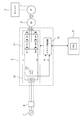
- FIG. 1 is a schematic diagram showing the overall configuration of a dry vacuum pump apparatus according to the present invention.
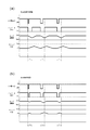
- 2 (a) and 2 (b) are graphs showing the control of the dry vacuum pump apparatus according to the prior art and the control of the dry vacuum pump according to the present invention, and FIG. 2 (a) is the dry vacuum pump according to the prior art.
- FIG. 2 (b) shows the control of the dry vacuum pump apparatus according to the present invention.
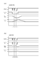
- FIGS. 3A and 3B are graphs showing the control of the dry vacuum pump apparatus according to the prior art and the control of the dry vacuum pump apparatus according to the present invention, and FIG. FIG. 3 (b) shows the control of the dry vacuum pump apparatus according to the present invention.
- FIG. 1 is a schematic diagram showing the overall configuration of a dry vacuum pump apparatus according to the present invention.
- the dry vacuum pump device includes a dry vacuum pump 1, a motor 2 that rotationally drives the dry vacuum pump 1, a motor driver 3 that controls the rotational speed of the motor 2, and operations of the motor driver 3. And a control device 4 for controlling.
- the motor driver 3 is connected to an AC power source 7 such as a commercial power source via a breaker 6.
- An intake port of the dry vacuum pump 1 is connected to a chamber 5 such as a semiconductor manufacturing apparatus, and the inside of the chamber 5 is configured to be evacuated by the dry vacuum pump 1.
- the motor driver 3 includes a converter 10 that converts AC power supplied from the AC power source 7 into DC power, an inverter 11 that converts the converted DC power into AC power having a desired frequency, and a switching element S1 of the inverter 11. And a driver control unit 12 for sending a gate drive signal for commanding the ON-OFF operation of S6 to the inverter 11.
- the converter 10 is provided with a capacitor C1 for smoothing the voltage.
- the driver control unit 12 generates a PWM signal based on the operation command speed of the dry vacuum pump 1 and transmits the PWM signal to the inverter 11.
- the control device 4 is configured to control the overall operation of the driver 3 and to communicate with an external host device.
- the driver control unit 12 receives a current value supplied from the motor driver 3 to the motor 2 as operation information of the motor 2, calculates the rotational speed of the motor 2 from the current value, and calculates a predetermined target rotational speed and a calculation.
- a PWM signal is generated based on the difference from the rotation speed thus transmitted, and is transmitted to the inverter 11 of the motor driver 3.
- the inverter 11 drives the switching elements S1 to S6 in accordance with the PWM signal, and applies an input voltage to the motor 2 for rotating the motor 2 at the target rotational speed. Further, the control device 4 is configured to transmit a start signal and a stop signal of the dry vacuum pump 1 to the driver control unit 12 in accordance with a user operation.
- the dry vacuum pump 1 is shut down during a power failure such as a momentary power failure, but regenerative power is generated in the motor 2 along with the deceleration during the shutdown. .
- This regenerative power returns to the inverter 11.
- the controller 4 transmits a start signal for the dry vacuum pump 1 to the motor driver 3 or continues to transmit the start signal even during a power failure, and the AC power source 7 drives the motor to the inverter 11. Since the electric power is supplied, the inverter 11 superimposes the regenerative power from the motor 2 and the motor driving power supplied from the AC power source 7.
- a dedicated inverter having a rated current larger than the rated current of the general-purpose inverter is used for the rated current of the switching element of the inverter.
- the relationship between the rated power of the general-purpose inverter and the rated current specification of the switching element used employs an original calculation method for each inverter manufacturer.
- Table 1 shows an example of this and the dedicated inverter used in the present invention. It is a comparison contrast table.
- the general-purpose inverter and the dedicated inverter are compared and compared for each rated power of the inverter.
- a dedicated inverter that is 1.5 to 2.5 times the general-purpose inverter is used for the rated current (setting) of the switching element.
- the rated current ratio of the dedicated inverter of the present invention to the general-purpose inverter is not limited to 1.5 times to 2.5 times, but in a range of about 1.5 times to 3.0 times. I just need it.
- FIG. 2A and 2B are graphs showing the control of the dry vacuum pump device according to the prior art and the control of the dry vacuum pump 1 according to the present invention
- FIG. 2A is a dry vacuum according to the prior art
- FIG. 2 (b) shows the control of the dry vacuum pump device 1 according to the present invention
- the horizontal axis represents time (t)
- 1 second is represented by 1 s.
- the vertical axis represents the input voltage (V) to the inverter, the inverter output, the pump speed (rpm), and the chamber internal pressure.
- V input voltage
- rpm pump speed
- FIG. 2A in the prior art, when the input voltage to the inverter is turned off due to momentary power interruption, the inverter output is also turned off.
- the inverter output OFF state continues for almost 1 second in order to wait for the motor speed to decrease and regenerative power not to be generated or to be sufficiently reduced. .
- the pump rotation speed decreases and the chamber internal pressure increases.
- FIG. 2 (a) three modes are shown for the case where the instantaneous stop time is short, slightly longer, and intermediate, but the inverter output is about 1 second regardless of the short stop time.
- the degree of decrease in the pump speed and the degree of increase in the chamber internal pressure are substantially the same.
- FIG. 3 (a) and 3 (b) are graphs showing the control of the dry vacuum pump device according to the prior art and the control of the dry vacuum pump device 1 according to the present invention
- FIG. 3 (a) is the dry vacuum pump device according to the prior art
- FIG. 3B shows the control of the dry vacuum pump device 1 according to the present invention.
- 3A and 3B the horizontal axis indicates time (t), and 1 second is 1 s.
- the vertical axis represents the input voltage (V) to the inverter, the inverter output, the pump speed (rpm), and the chamber internal pressure.
- V input voltage
- the instantaneous interruption occurs repeatedly within a short time (the figure shows the case where the instantaneous interruption occurs three times every 1 second)
- the input voltage turns off each time, and the inverter output turns off each time, but there is no need to wait for the regenerative power to drop, so when power is restored, the inverter output will be Even in this case, it recovers immediately and turns on.
- the pump rotational speed slightly decreases each time, but when the power is restored, the inverter output immediately recovers. Therefore, the pump rotational speed decreases little and the chamber internal pressure increases slightly. Therefore, the chamber internal pressure immediately reaches the lowest level (Low) as the inverter output recovers.
- the inverter output can be turned on immediately after the power is restored. In order to recover, fluctuations in the chamber internal pressure can be suppressed.
- the present invention can be used for a dry vacuum pump device that can immediately restart the rotation of the vacuum pump after a power failure such as “instantaneous power failure”, which indicates a power failure that occurs in a short time of about 1 second or less, and a control method thereof.
- a power failure such as “instantaneous power failure”, which indicates a power failure that occurs in a short time of about 1 second or less
Landscapes
- Engineering & Computer Science (AREA)
- Power Engineering (AREA)
- Control Of Ac Motors In General (AREA)
Abstract
本発明は、1秒以下程度の短時間に発生する停電を指す、「瞬停」等の停電後、真空ポンプの回転を直ちに再起動できるドライ真空ポンプ装置およびその制御方法に関するものである。 ドライ真空ポンプ装置は、ドライ真空ポンプ(1)と、ドライ真空ポンプ(1)を駆動するモータ(2)と、モータ(2)に可変周波数の交流電力を供給しモータ(2)の回転速度を制御するインバータ(11)と、インバータ(11)を制御する制御装置(4)とを備え、制御装置(4)は、停電時にモータ側で発生する回生電力をインバータ(11)のパワーデバイスで消費しつつ、復電直後からインバータ(11)からモータ(2)への駆動電力を供給するようにインバータ(11)を制御する。
Description
本発明は、ドライ真空ポンプ装置およびその制御方法に係り、特に1秒以下程度の短時間に発生する停電を指す、「瞬停」等の停電後、真空ポンプの回転を直ちに再起動できるドライ真空ポンプ装置およびその制御方法に関するものである。
半導体デバイス、液晶、太陽光パネル、LED等の生産ラインにおいて、各種処理を行うチャンバ内を真空排気するためにドライ真空ポンプ装置が広く使用されている。ドライ真空ポンプ装置が、1秒以下程度の短時間に発生する停電を指す、「瞬停」等の停電によってポンプ運転制御が停止すると、真空ポンプの排気によって実現されていたチャンバの内圧が上昇し、チャンバ内のプロセス条件変化が発生する事で製造処理を続行することができず、生産ラインが停止する。停電によるドライ真空ポンプ装置のポンプ運転制御停止時間が長引くほど、甚大な被害につながるため、復電後は直ちにドライ真空ポンプ装置を再起動することが望まれる。
一般的に、ドライ真空ポンプ装置は、ドライ真空ポンプと、ドライ真空ポンプを駆動するモータと、モータの回転速度(回転周波数)を制御するインバータと、インバータの動作を制御する制御装置とを備え、モータに可変周波数の交流電力を供給することにより、ドライ真空ポンプの運転速度を制御するようにしている。
上述したインバータを備えたドライ真空ポンプ装置において、停電によってインバータ装置から真空ポンプ駆動モータへの電力供給が停止するため、真空ポンプとしては運転停止状態になり、ポンプ駆動モータは減速状態となる。
その後、入力電源が復電すると、直後にインバータ装置の出力制御は機能回復するが、特にロータ側に永久磁石を用いた、直流無整流子電動機の場合、このポンプモータが回転状態にある時、インバータ出力を再開しようとすると、あたかもこのモータ自身がインバータ出力端子側に電力を供給する発電機であるかのごとく、大きな回生電力が発生する。
その後、入力電源が復電すると、直後にインバータ装置の出力制御は機能回復するが、特にロータ側に永久磁石を用いた、直流無整流子電動機の場合、このポンプモータが回転状態にある時、インバータ出力を再開しようとすると、あたかもこのモータ自身がインバータ出力端子側に電力を供給する発電機であるかのごとく、大きな回生電力が発生する。
この回生電力はインバータ出力端子に発生するため、インバータとしてみると、インバータ自身がモータへ供給すべき電力に重畳してモータからの回生電力を制御する事となるため、インバータが処理すべき電力は、通常使用の領域を超えて制御する事になる。このためインバータ内部にあるスイッチング素子に対しては、通常使用以上の電力・電流が供給される場合があるため、回生電力発生時に故障を誘発する可能性がある。このスイッチング素子を保護するための手段として、一般的な手法では回生電力消費用の回生抵抗を設け、回生分の電力をこの抵抗により熱放散させる方法や、回生抵抗を設けずに、回生電力を電源側(入力側)に戻す制御を行う方法、或いは、モータが所定の回転数以下になるまで、インバータ制御は復帰せず、回生電力をモータ減速より自然減衰させる方法が提唱されている。
しかしながら、回生電力を回生抵抗で消費するように構成する場合には、回生抵抗および回生抵抗に回生電流を流すためのスイッチング機構が必要となる。そのため、部品点数が多くなり、インバータ装置全体が大型化し且つコストが上昇するという課題点がある。
また、回生電力を電源側(入力側)に戻す制御を行う場合には、インバータ内のスイッチング素子等のパワーデバイスの制御が難しく、制御用回路を設けるコストも上昇するので、回生電力を入力側に返す制御にも課題点がある。
また、回生電力を電源側(入力側)に戻す制御を行う場合には、インバータ内のスイッチング素子等のパワーデバイスの制御が難しく、制御用回路を設けるコストも上昇するので、回生電力を入力側に返す制御にも課題点がある。
そこで、上述の問題点を解消し装置コストの上昇を避けるために、通常、ドライ真空ポンプ装置においては、停電時に、回生電力がインバータ側に返らないよう、ポンプ・モータが所定の回転数以下になるまで、インバータ制御は復帰せず、回生電力をモータ減速にて自然消費させ、ポンプ・モータが所定の回転数以下になった後、ドライ真空ポンプを再起動するようにしている。
ドライ真空ポンプでは、定格回転数で運転中に停電が発生した場合、ポンプケーシング内の圧力が非常に低く保たれている場合があり、インバータからの駆動電流供給が停止した場合にも、短時間では回転減速が発生せず、ほぼ定格回転数で回転継続している場合がある。
ドライ真空ポンプでは、定格回転数で運転中に停電が発生した場合、ポンプケーシング内の圧力が非常に低く保たれている場合があり、インバータからの駆動電流供給が停止した場合にも、短時間では回転減速が発生せず、ほぼ定格回転数で回転継続している場合がある。
この状態にあって復電し、ポンプモータに通電を再開すると、モータが発電機として機能するため、インバータ出力端子には回生電力が発生する。この回生電力によりインバータ出力端子に発生する電流は、モータ駆動時にインバータが出力する電流とほぼ同等の電流が発生する可能性がある。したがって、インバータ側スイッチング素子は、通常出力する電流の2倍程度の電流が処理可能で無ければならない。
一般的なインバータ装置を使ったドライ真空ポンプでは、この回生電力が発生する事を避けるため、停電発生後の復電動作ではポンプモータの回転が充分に低下し、回生電力が発生しない条件に達するのを待って、インバータ側の出力を開始する方法が使われている。
一般的なインバータ装置を使ったドライ真空ポンプでは、この回生電力が発生する事を避けるため、停電発生後の復電動作ではポンプモータの回転が充分に低下し、回生電力が発生しない条件に達するのを待って、インバータ側の出力を開始する方法が使われている。
また、半導体製造装置に対して、ドライ真空ポンプを使用する場合、半導体製造装置業界標準として制定されているSEMI規格にて、瞬時停電に関する規定が有り、1秒以内の停電発生時には通常通りの運転継続と復電時には速やかなポンプ回転復帰が求められている。
したがって、半導体製造装置向けのドライ真空ポンプでは、停電発生復電後のポンプモータ復帰に対する制御方法が、大きな課題となっている。
したがって、半導体製造装置向けのドライ真空ポンプでは、停電発生復電後のポンプモータ復帰に対する制御方法が、大きな課題となっている。
しかしながら、上述したように回生電力がモータ側で消費されるまでドライ真空ポンプの再起動を待つという方法では、ドライ真空ポンプが減速している間にチャンバの内圧が上昇し、プロセス条件が悪化するため、生産ラインに与える影響が大きすぎるという問題点がある。
そのため、本発明者らは、停電時にモータ側で発生する回生電力をインバータのパワーデバイスで消費しつつ、1秒以内の短時間に復電した場合は、直ちにインバータに電力を供給し、ドライ真空ポンプを再起動する方策について検討を重ねたものである。
そのため、本発明者らは、停電時にモータ側で発生する回生電力をインバータのパワーデバイスで消費しつつ、1秒以内の短時間に復電した場合は、直ちにインバータに電力を供給し、ドライ真空ポンプを再起動する方策について検討を重ねたものである。
本発明は、上述の事情に鑑みなされたもので、停電時にモータ側で発生する回生電力をインバータのパワーデバイスで消費しつつ復電後に直ちに電源から電力をインバータに供給することを可能とし、復電後に直ちに真空ポンプを再起動することが可能なドライ真空ポンプ装置およびその制御方法を提供することを目的とする。
上述の目的を達成するため、本発明のドライ真空ポンプ装置の第1の態様は、ドライ真空ポンプと、前記ドライ真空ポンプを駆動するモータと、前記モータに可変周波数の交流電力を供給しモータの回転速度を制御するインバータと、前記インバータを制御する制御装置とを備え、前記制御装置は、停電時にモータ側で発生する回生電力を前記インバータのパワーデバイスで消費しつつ、復電直後から前記インバータからモータへの駆動電力を供給するように前記インバータを制御することを特徴とする。
本発明のドライ真空ポンプ装置の第2の態様は、ドライ真空ポンプと、前記ドライ真空ポンプを駆動するモータと、前記モータに可変周波数の交流電力を供給しモータの回転速度を制御するインバータと、前記インバータを制御する制御装置とを備え、前記インバータは、該インバータのスイッチング素子の定格電流が汎用インバータのスイッチング素子の定格電流の1.5倍~3.0倍であるインバータであることを特徴とする。
本発明のドライ真空ポンプ装置の制御方法は、ドライ真空ポンプと、前記ドライ真空ポンプを駆動するモータと、前記モータに可変周波数の交流電力を供給しモータの回転速度を制御するインバータとを備えたドライ真空ポンプ装置の制御方法において、停電と同時に前記インバータの出力を停止し、復電した場合、直後から前記インバータの出力を開始する制御を行うことを特徴とする。
本発明によれば、停電時にモータ側で発生する回生電力をインバータのパワーデバイスで消費しつつ復電後に直ちに電源から電力をインバータに供給することが可能であるため、復電後に直ちにドライ真空ポンプを再起動することが可能である。従って、ドライ真空ポンプによって排気されるチャンバの内圧の変動を抑制することができる。
以下、本発明に係るドライ真空ポンプ装置およびその制御方法の実施形態を図1乃至図3を参照して説明する。図1乃至図3において、同一または相当する構成要素には、同一の符号を付して重複した説明を省略する。
図1は、本発明に係るドライ真空ポンプ装置の全体構成を示す模式図である。図1に示すように、ドライ真空ポンプ装置は、ドライ真空ポンプ1と、ドライ真空ポンプ1を回転駆動するモータ2と、モータ2の回転速度を制御するモータドライバ3と、モータドライバ3の動作を制御する制御装置4とを備えている。モータドライバ3は、ブレーカ6を介して商用電源等のAC電源7に接続されている。ドライ真空ポンプ1の吸気口は半導体製造装置等のチャンバ5に接続されており、チャンバ5内をドライ真空ポンプ1により真空排気するように構成されている。
図1は、本発明に係るドライ真空ポンプ装置の全体構成を示す模式図である。図1に示すように、ドライ真空ポンプ装置は、ドライ真空ポンプ1と、ドライ真空ポンプ1を回転駆動するモータ2と、モータ2の回転速度を制御するモータドライバ3と、モータドライバ3の動作を制御する制御装置4とを備えている。モータドライバ3は、ブレーカ6を介して商用電源等のAC電源7に接続されている。ドライ真空ポンプ1の吸気口は半導体製造装置等のチャンバ5に接続されており、チャンバ5内をドライ真空ポンプ1により真空排気するように構成されている。
モータドライバ3は、AC電源7から供給された交流電力を直流電力に変換するコンバータ10と、変換された直流電力を所望の周波数を有する交流電力に変換するインバータ11と、インバータ11のスイッチング素子S1~S6のON-OFF動作を指令するゲートドライブ信号をインバータ11に送るドライバ制御部12とを備えている。コンバータ10には、電圧を平滑化するためのコンデンサC1が備えられている。
ドライバ制御部12は、ドライ真空ポンプ1の運転指令速度等に基づいてPWM信号を生成し、これをインバータ11に送信する。制御装置4は、ドライバ3全体の動作を制御し、さらに外部の上位機器との通信をするように構成されている。ドライバ制御部12は、モータ2の運転情報として、モータドライバ3からモータ2に供給される電流値を受け取り、この電流値からモータ2の回転速度を算出し、予め定められた目標回転速度と算出された回転速度との差に基づいてPWM信号を生成し、これをモータドライバ3のインバータ11に送信する。インバータ11はPWM信号に従ってスイッチング素子S1~S6を駆動し、モータ2を目標回転速度で回転させるための入力電圧をモータ2に印加する。さらに、制御装置4は、ユーザの操作に従ってドライ真空ポンプ1の起動信号および停止信号をドライバ制御部12に送信するように構成されている。
図1に示すように構成されたドライ真空ポンプ装置において、瞬停等の停電時には、ドライ真空ポンプ1が運転停止になるが、この運転停止時の減速に伴い、モータ2において回生電力が発生する。この回生電力はインバータ11に返ってくる。
本発明においては、停電後の復電時に制御装置4からモータドライバ3にドライ真空ポンプ1の起動信号を送信、或いは停電最中も起動信号を送信し続け、AC電源7からインバータ11にモータ駆動用電力を供給するように構成しているため、インバータ11にはモータ2からの回生電力とAC電源7から供給されるモータ駆動用電力とが重畳されることになる。すなわち、インバータ11には、モータ2からの回生電流とAC電源7からのモータ駆動用電流とが重畳されることになるため、この重畳される大きな電流にインバータ11が耐えられるようにする必要がある。そのため、本発明においては、インバータのスイッチング素子の定格電流について、汎用インバータの定格電流よりも大きい定格電流の専用インバータを用いている。
本発明においては、停電後の復電時に制御装置4からモータドライバ3にドライ真空ポンプ1の起動信号を送信、或いは停電最中も起動信号を送信し続け、AC電源7からインバータ11にモータ駆動用電力を供給するように構成しているため、インバータ11にはモータ2からの回生電力とAC電源7から供給されるモータ駆動用電力とが重畳されることになる。すなわち、インバータ11には、モータ2からの回生電流とAC電源7からのモータ駆動用電流とが重畳されることになるため、この重畳される大きな電流にインバータ11が耐えられるようにする必要がある。そのため、本発明においては、インバータのスイッチング素子の定格電流について、汎用インバータの定格電流よりも大きい定格電流の専用インバータを用いている。
汎用インバータの定格電力と、使用するスイッチング素子の定格電流仕様の関係は、インバータメーカ各社で独自の計算方法を採用しているが、表1は、その一例と、本発明で用いる専用インバータとの比較対比表である。
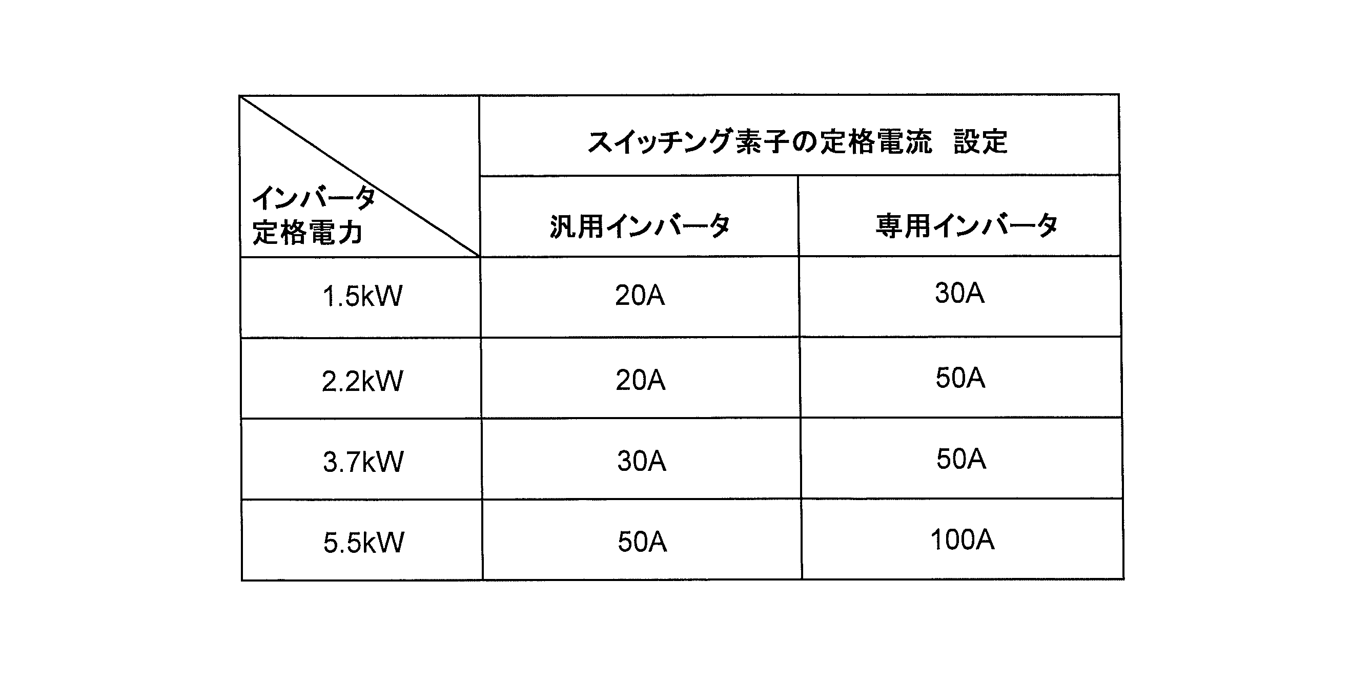
表1では、スイッチング素子の定格電流について、インバータの定格電力毎に、汎用インバータと専用インバータとを比較対比している。表1から明らかなように、本発明においては、スイッチング素子の定格電流(設定)について、汎用インバータの1.5倍~2.5倍の専用インバータを用いている。本発明者らの知見によれば、汎用インバータに対する本発明の専用インバータの定格電流比は、1.5倍~2.5倍に限らず、1.5倍~3.0倍程度の範囲であればよい。
表1では、スイッチング素子の定格電流について、インバータの定格電力毎に、汎用インバータと専用インバータとを比較対比している。表1から明らかなように、本発明においては、スイッチング素子の定格電流(設定)について、汎用インバータの1.5倍~2.5倍の専用インバータを用いている。本発明者らの知見によれば、汎用インバータに対する本発明の専用インバータの定格電流比は、1.5倍~2.5倍に限らず、1.5倍~3.0倍程度の範囲であればよい。
このように、インバータ11を大電流に耐えられるインバータで構成することにより、停電時にモータ側で発生する回生電力をインバータ11のパワーデバイスで消費しつつAC電源7から電力をインバータ11に供給することにより、1秒以内の短時間の停電発生、復電後は直ちにドライ真空ポンプ1を再起動することが可能である。
図2(a),(b)は、従来技術によるドライ真空ポンプ装置の制御と本発明によるドライ真空ポンプ1の制御を対比して示すグラフであり、図2(a)は従来技術によるドライ真空ポンプ装置の制御を示し、図2(b)は本発明によるドライ真空ポンプ装置1の制御を示す。図2(a),(b)において、横軸は時間(t)を示し、1秒は1sで示す。縦軸は、インバータへの入力電圧(V)、インバータ出力、ポンプ回転数(rpm)およびチャンバ内圧を示す。
図2(a)に示すように、従来技術においては、瞬停によってインバータへの入力電圧がOFFになると、インバータ出力もOFFになる。瞬停後に復電しても、モータの回転数が低下し、回生電力が発生しない、もしくは、発生する回生電力が十分に小さくなるのを待つため、インバータ出力OFFの状態は1秒近く継続する。インバータ出力がOFFの間に、ポンプ回転数は低下し、チャンバ内圧は上昇する。図2(a)においては瞬停の時間が短い場合と、やや長い場合と、中間の場合の三つの態様が示されているが、瞬停の時間の長短に拘わらずインバータ出力は約1秒間OFFとなり、いずれの態様においてもポンプ回転数の低下度合およびチャンバ内圧の上昇度合は概略同一である。
図2(a)に示すように、従来技術においては、瞬停によってインバータへの入力電圧がOFFになると、インバータ出力もOFFになる。瞬停後に復電しても、モータの回転数が低下し、回生電力が発生しない、もしくは、発生する回生電力が十分に小さくなるのを待つため、インバータ出力OFFの状態は1秒近く継続する。インバータ出力がOFFの間に、ポンプ回転数は低下し、チャンバ内圧は上昇する。図2(a)においては瞬停の時間が短い場合と、やや長い場合と、中間の場合の三つの態様が示されているが、瞬停の時間の長短に拘わらずインバータ出力は約1秒間OFFとなり、いずれの態様においてもポンプ回転数の低下度合およびチャンバ内圧の上昇度合は概略同一である。
図2(b)に示すように、本発明においては、瞬停によってインバータへの入力電圧がOFFになるとインバータ出力もOFFになるが、復電すると、モータの回転数低下によって発生する回生電力が低下するのを待つことなく、直ちにインバータ出力はONになる。図2(b)においても、瞬停の時間が短い場合と、やや長い場合と、中間の場合の三つの態様が示されているが、いずれの態様においても復電すると直ちにインバータ出力はONになる。このように、復電後にインバータ出力が直ちにONになるために、ポンプ回転数の低下およびチャンバ内圧の上昇は抑制される。
図3(a),(b)は、従来技術によるドライ真空ポンプ装置の制御と本発明によるドライ真空ポンプ装置1の制御を示すグラフであり、図3(a)は従来技術によるドライ真空ポンプ装置の制御を示し、図3(b)は本発明によるドライ真空ポンプ装置1の制御を示す。図3(a),(b)において、横軸は時間(t)を示し、1秒は1sで示す。縦軸は、インバータへの入力電圧(V)、インバータ出力、ポンプ回転数(rpm)およびチャンバ内圧を示す。
図3(a)に示すように、従来技術においては、短時間の間に瞬停が繰返し起こると(図では、瞬停が1秒おきに三回繰返し起こった場合を示す)、最初の瞬停でインバータへの入力電圧がOFFになると、インバータ出力はOFFとなり、その後一時的に復電しても、発生する回生電力の低下を待つため次の瞬停までにインバータ出力がONになることはなく、インバータ出力は最後の瞬停までOFF状態が続く。最後の瞬停後に復電すると時間遅れをもってインバータ出力はONとなる。このように、短時間の間に瞬停が繰返し起こると、インバータ出力は、かなり長い時間(図示例では3秒)に亘ってOFF状態になる。その間、ポンプ回転数は低下し続け0rpmまで低下する。そのため、チャンバ内圧は最高レベル(High)まで上昇する。
図3(a)に示すように、従来技術においては、短時間の間に瞬停が繰返し起こると(図では、瞬停が1秒おきに三回繰返し起こった場合を示す)、最初の瞬停でインバータへの入力電圧がOFFになると、インバータ出力はOFFとなり、その後一時的に復電しても、発生する回生電力の低下を待つため次の瞬停までにインバータ出力がONになることはなく、インバータ出力は最後の瞬停までOFF状態が続く。最後の瞬停後に復電すると時間遅れをもってインバータ出力はONとなる。このように、短時間の間に瞬停が繰返し起こると、インバータ出力は、かなり長い時間(図示例では3秒)に亘ってOFF状態になる。その間、ポンプ回転数は低下し続け0rpmまで低下する。そのため、チャンバ内圧は最高レベル(High)まで上昇する。
図3(b)に示すように、本発明においては、短時間の間に瞬停が繰返し起こると(図では、瞬停が1秒おきに三回繰返し起こった場合を示す)、インバータへの入力電圧がその都度OFFになり、インバータ出力はその都度OFFになるが、回生電力が低下するのを待つことがないため、復電するとインバータ出力は、瞬停の時間の長短に拘わらずいずれの場合も直ちに回復してONになる。瞬停が起こるとポンプ回転数はその都度僅かに低下するが、復電すると直ちにインバータ出力が回復するため、ポンプ回転数の低下度合は少なく、またチャンバ内圧の上昇度合も僅かである。そのため、インバータ出力の回復とともにチャンバ内圧は最低レベル(Low)に直ちに到達する。このように本発明によれば、停電によってインバータ出力がOFFになっても、復電後直ちにインバータ出力をONにすることが可能であり、真空ポンプの回転数が定格回転数にわずかな時間で回復するため、チャンバ内圧の変動を抑制することができる。
これまで本発明の実施形態について説明したが、本発明は上述の実施形態に限定されず、その技術思想の範囲内において、種々の異なる形態で実施されてよいことは勿論である。
本発明は、1秒以下程度の短時間に発生する停電を指す、「瞬停」等の停電後、真空ポンプの回転を直ちに再起動できるドライ真空ポンプ装置およびその制御方法に利用可能である。
1 ドライ真空ポンプ
2 モータ
3 モータドライバ
4 制御装置
5 チャンバ
6 ブレーカ
7 AC電源
10 コンバータ
11 インバータ
12 ドライバ制御部
C1 コンデンサ
S1~S6 スイッチング素子
2 モータ
3 モータドライバ
4 制御装置
5 チャンバ
6 ブレーカ
7 AC電源
10 コンバータ
11 インバータ
12 ドライバ制御部
C1 コンデンサ
S1~S6 スイッチング素子
Claims (3)
- ドライ真空ポンプと、
前記ドライ真空ポンプを駆動するモータと、
前記モータに可変周波数の交流電力を供給しモータの回転速度を制御するインバータと、
前記インバータを制御する制御装置とを備え、
前記制御装置は、停電時にモータ側で発生する回生電力を前記インバータのパワーデバイスで消費しつつ、復電直後から前記インバータからモータへの駆動電力を供給するように前記インバータを制御することを特徴とするドライ真空ポンプ装置。 - ドライ真空ポンプと、
前記ドライ真空ポンプを駆動するモータと、
前記モータに可変周波数の交流電力を供給しモータの回転速度を制御するインバータと、
前記インバータを制御する制御装置とを備え、
前記インバータは、該インバータのスイッチング素子の定格電流が汎用インバータのスイッチング素子の定格電流の1.5倍~3.0倍であるインバータであることを特徴とするドライ真空ポンプ装置。 - ドライ真空ポンプと、前記ドライ真空ポンプを駆動するモータと、前記モータに可変周波数の交流電力を供給しモータの回転速度を制御するインバータとを備えたドライ真空ポンプ装置の制御方法において、
停電と同時に前記インバータの出力を停止し、復電した場合、直後から前記インバータの出力を開始する制御を行うことを特徴とするドライ真空ポンプ装置の制御方法。
Applications Claiming Priority (2)
| Application Number | Priority Date | Filing Date | Title |
|---|---|---|---|
| JP2015031060A JP5918406B1 (ja) | 2015-02-19 | 2015-02-19 | ドライ真空ポンプ装置およびその制御方法 |
| JP2015-031060 | 2015-02-19 |
Publications (1)
| Publication Number | Publication Date |
|---|---|
| WO2016132573A1 true WO2016132573A1 (ja) | 2016-08-25 |
Family
ID=55974027
Family Applications (1)
| Application Number | Title | Priority Date | Filing Date |
|---|---|---|---|
| PCT/JP2015/071321 Ceased WO2016132573A1 (ja) | 2015-02-19 | 2015-07-28 | ドライ真空ポンプ装置およびその制御方法 |
Country Status (2)
| Country | Link |
|---|---|
| JP (1) | JP5918406B1 (ja) |
| WO (1) | WO2016132573A1 (ja) |
Cited By (1)
| Publication number | Priority date | Publication date | Assignee | Title |
|---|---|---|---|---|
| GB2630273A (en) * | 2023-05-16 | 2024-11-27 | Edwards Ltd | Circuit for driving a motor of a vacuum pump, vacuum pump assembly, and method |
Citations (4)
| Publication number | Priority date | Publication date | Assignee | Title |
|---|---|---|---|---|
| JP2000341960A (ja) * | 1999-05-27 | 2000-12-08 | Fuji Electric Co Ltd | 半導体装置 |
| US20070052379A1 (en) * | 2005-09-05 | 2007-03-08 | Bum-Seok Suh | Motor driving inverter circuit module, motor driving apparatus having the motor driving inverter circuit module, and inverter integrated circuit package |
| JP2007143332A (ja) * | 2005-11-21 | 2007-06-07 | Matsushita Electric Ind Co Ltd | モータ駆動装置およびそれを備えた冷凍装置 |
| JP2011069294A (ja) * | 2009-09-25 | 2011-04-07 | Ebara Corp | 真空ポンプシステム、及びその運転方法 |
Family Cites Families (3)
| Publication number | Priority date | Publication date | Assignee | Title |
|---|---|---|---|---|
| JPH07327375A (ja) * | 1994-05-31 | 1995-12-12 | Ebara Corp | 真空ポンプにおける瞬停・瞬時電圧低下補償装置 |
| JP5049251B2 (ja) * | 2008-11-14 | 2012-10-17 | 株式会社安川電機 | モータ制御装置 |
| JP2012249494A (ja) * | 2011-05-31 | 2012-12-13 | Hitachi Industrial Equipment Systems Co Ltd | 電源回生装置 |
-
2015
- 2015-02-19 JP JP2015031060A patent/JP5918406B1/ja active Active
- 2015-07-28 WO PCT/JP2015/071321 patent/WO2016132573A1/ja not_active Ceased
Patent Citations (4)
| Publication number | Priority date | Publication date | Assignee | Title |
|---|---|---|---|---|
| JP2000341960A (ja) * | 1999-05-27 | 2000-12-08 | Fuji Electric Co Ltd | 半導体装置 |
| US20070052379A1 (en) * | 2005-09-05 | 2007-03-08 | Bum-Seok Suh | Motor driving inverter circuit module, motor driving apparatus having the motor driving inverter circuit module, and inverter integrated circuit package |
| JP2007143332A (ja) * | 2005-11-21 | 2007-06-07 | Matsushita Electric Ind Co Ltd | モータ駆動装置およびそれを備えた冷凍装置 |
| JP2011069294A (ja) * | 2009-09-25 | 2011-04-07 | Ebara Corp | 真空ポンプシステム、及びその運転方法 |
Cited By (1)
| Publication number | Priority date | Publication date | Assignee | Title |
|---|---|---|---|---|
| GB2630273A (en) * | 2023-05-16 | 2024-11-27 | Edwards Ltd | Circuit for driving a motor of a vacuum pump, vacuum pump assembly, and method |
Also Published As
| Publication number | Publication date |
|---|---|
| JP5918406B1 (ja) | 2016-05-18 |
| JP2016152767A (ja) | 2016-08-22 |
Similar Documents
| Publication | Publication Date | Title |
|---|---|---|
| JP5398815B2 (ja) | 永久磁石同期モータの駆動装置、空気調和装置、換気扇の駆動装置、洗濯機、自動車及び車両 | |
| US9041327B2 (en) | Method and apparatus for overvoltage protection and reverse motor speed control for motor drive power loss events | |
| EP2675060A1 (en) | Power conversion apparatus | |
| JP2015175290A (ja) | 電動ポンプ | |
| JP2019203509A (ja) | 真空ポンプおよびその運転方法 | |
| CN104980066A (zh) | 排水泵用直流无刷电动机系统、及其控制方法和控制装置 | |
| CN107859645B (zh) | 风机控制方法、系统及空调 | |
| JP5918406B1 (ja) | ドライ真空ポンプ装置およびその制御方法 | |
| JPH11103585A (ja) | インバータ保護装置 | |
| CN110945775B (zh) | 真空泵和电动机控制装置 | |
| JP2005337234A (ja) | インバータ駆動圧縮機の予熱運転方法およびその装置 | |
| TWI707534B (zh) | 乾式真空泵浦裝置及其控制方法與控制程式 | |
| JP4422514B2 (ja) | 電力変換装置 | |
| JP7424772B2 (ja) | 真空排気装置及びその運転方法 | |
| US20130280101A1 (en) | Electric pump device | |
| KR102503330B1 (ko) | 비상운전이 가능한 유도전동기용 제어장치, 시스템 및 그 구동방법 | |
| WO2023000683A1 (zh) | 基于无感矢量控制的永磁同步电机运行的控制方法 | |
| JP2017145726A (ja) | ドライ真空ポンプ装置、その制御方法および制御プログラム | |
| WO2018164000A1 (ja) | モータ駆動装置 | |
| CN111149288B (zh) | 电动机控制装置 | |
| KR20150055555A (ko) | 진공 펌프 및 그 운전 방법 | |
| JP2015019532A (ja) | 可変速揚水発電システムの同期始動制御装置及び同期始動制御方法 | |
| KR20130031123A (ko) | Bldc 팬 모터 제어 방법 | |
| JP2022086670A (ja) | 車載用電動圧縮機 | |
| JP2014176129A (ja) | 電動ポンプの駆動制御装置 |
Legal Events
| Date | Code | Title | Description |
|---|---|---|---|
| 121 | Ep: the epo has been informed by wipo that ep was designated in this application |
Ref document number: 15882674 Country of ref document: EP Kind code of ref document: A1 |
|
| NENP | Non-entry into the national phase |
Ref country code: DE |
|
| 122 | Ep: pct application non-entry in european phase |
Ref document number: 15882674 Country of ref document: EP Kind code of ref document: A1 |