WO2016132398A1 - 細胞培養加工設備 - Google Patents
細胞培養加工設備 Download PDFInfo
- Publication number
- WO2016132398A1 WO2016132398A1 PCT/JP2015/000802 JP2015000802W WO2016132398A1 WO 2016132398 A1 WO2016132398 A1 WO 2016132398A1 JP 2015000802 W JP2015000802 W JP 2015000802W WO 2016132398 A1 WO2016132398 A1 WO 2016132398A1
- Authority
- WO
- WIPO (PCT)
- Prior art keywords
- manipulator
- teaching data
- cell culture
- operator
- unit
- Prior art date
- Legal status (The legal status is an assumption and is not a legal conclusion. Google has not performed a legal analysis and makes no representation as to the accuracy of the status listed.)
- Ceased
Links
Images




Classifications
-
- C—CHEMISTRY; METALLURGY
- C12—BIOCHEMISTRY; BEER; SPIRITS; WINE; VINEGAR; MICROBIOLOGY; ENZYMOLOGY; MUTATION OR GENETIC ENGINEERING
- C12M—APPARATUS FOR ENZYMOLOGY OR MICROBIOLOGY; APPARATUS FOR CULTURING MICROORGANISMS FOR PRODUCING BIOMASS, FOR GROWING CELLS OR FOR OBTAINING FERMENTATION OR METABOLIC PRODUCTS, i.e. BIOREACTORS OR FERMENTERS
- C12M3/00—Tissue, human, animal or plant cell, or virus culture apparatus
-
- B—PERFORMING OPERATIONS; TRANSPORTING
- B25—HAND TOOLS; PORTABLE POWER-DRIVEN TOOLS; MANIPULATORS
- B25J—MANIPULATORS; CHAMBERS PROVIDED WITH MANIPULATION DEVICES
- B25J13/00—Controls for manipulators
- B25J13/08—Controls for manipulators by means of sensing devices, e.g. viewing or touching devices
Definitions
- the present invention relates to a cell culture processing facility provided with a working chamber for processing, processing and culturing cells in regenerative medicine.
- human cells are processed, processed, and cultured (hereinafter collectively referred to as “cell culture”) to produce target cells.
- cell culture In order to obtain the target cells, the step of disinfecting the collected cells, the step of isolating the target cells, the step of suspending the isolated cells in the solution, the step of seeding the cells in the solution in the medium, the seeding A series of steps such as a step of culturing cells in a cultured medium and a step of subculture are performed.
- each step includes various operations such as adjusting a liquid sample containing cells to a predetermined temperature, adding chemicals to the cells and stirring them, and the operations include processing, processing contents, and target cell. It depends on the type. For this reason, cell culture is performed based on a procedure manual called a protocol that describes the contents of operations performed in each step, thereby improving reproducibility when creating target cells.
- Cited Document 1 discloses an automatic cell culture apparatus in which an articulated robot is disposed in a housing having an opening / closing door on the front side, and a cell culture device is disposed on the back side opposite to the front side. Are listed. However, in the cited document 1, there is no description of how to realize the operation of a skilled worker by the operation robot.
- Reference 2 describes a teleoperator system that drives an end effector that performs treatment of a patient's tissue at a surgical site by operating a controller provided in a remotely located operator control station.
- a controller provided in a remotely located operator control station.
- the surgical operation realized by the end effector changes depending on the skill of the operator who performs the operation of the controller. For this reason, the technique which supplements the skill of the unskilled person in cell culture is not suggested.
- Japanese Patent No. 5416919 Claim 1 paragraphs 0018 to 0021, FIGS. Japanese Patent No. 3582777: Claim 1, FIG.
- the present invention has been made under such circumstances, and an object of the present invention is to provide a cell culture processing facility capable of reproducing the skill of an expert.
- the cell culture processing equipment of the present invention includes a culture chamber for cell culture, a suction device for sucking fluid in the culture vessel, and an incubator in which the culture container is housed, A manipulator that is remotely operated for each of the operation on the culture vessel and the operation on the suction tool and is equipped with a movable imaging unit and a tactile function, and provided in the work chamber; A memory that is provided outside the work chamber and stores operation data of the manipulator as teaching data when an operation on at least one of the culture vessel and the suction tool is executed by the manipulator by an operation unit that transmits the movement of the operator. And And And a control unit for reading the teaching data and causing the manipulator to automatically execute at least one of the culture vessel and the suction tool.
- the cell culture processing facility may have the following features.
- a plurality of the teaching data is prepared in accordance with a state of an operation target for at least one of the culture vessel and the suction tool, and the movable type mounted on the manipulator from the plurality of teaching data.
- Teaching data selected based on an image obtained by the imaging unit is used.
- a manual selection selection unit is provided for an operator to select teaching data to be used from the plurality of teaching data based on the image obtained by the movable imaging unit in (a). Was it.
- a selection unit for automatic selection for automatically selecting teaching data to be used from the plurality of teaching data based on an image obtained by the movable imaging unit is provided.
- (C) a switching unit that switches whether the operator's movement is “valid” or “invalid” with respect to the remote operation, and after being switched to “invalid” by the switching unit,
- the manipulator is configured to automatically execute the operation from a predetermined initial state based on teaching data read from the memory.
- the control unit is configured to return to the initial state after the manipulator automatically executes the operation.
- the present invention provides an operation unit that is provided outside a work chamber and that transmits an operator's movement when at least one of the culture vessel for cell culture and the suction tool is operated by the manipulator provided in the work chamber. Since the operation data is stored as teaching data, the operation can be automatically controlled.
- the cell culture processing equipment of the present invention is provided in a work table 2 in which various devices for cell culture are arranged in a work room 1 partitioned from an external atmosphere by a housing 10 and a position facing the work table 2. And a manipulator 3 for executing the operation of the device.
- the work table 2 is provided at a height position accessible by a hand 32 of a manipulator 3 described later.
- an incubator 21 for storing a dish 26 as a culture vessel
- separated with the work table 2 is shown.
- the incubator 21 includes a shelf that can accommodate a large number of dishes 26 in a housing that can keep the inside at a constant temperature.
- FIG. 1 shows an example of an incubator 21 in which two rows of front and rear shelves on the front side and the back side are arranged as viewed from the manipulator 3 side. In this case, the dish 26 accommodated in each shelf can be accessed from the near side by configuring the shelf in the front so as to be movable up and down.
- the pipette device 22 is used for an operation of sucking a predetermined amount of a liquid sample or various chemicals from a fluid container such as the dish 26 and injecting the liquid sample or various chemicals into another container.
- the pipette device 22 is detachably held on a stand arranged on the upper surface of the work table 2, for example.
- a plurality of pipette tips 221 configured to be detachable from the pipette device 22 and exchanged according to the fluid to be handled are held by the tip stand 222.
- the centrifuge tube 231 is held in a holder (not shown) of a rotating rotor housed in a casing, and the rotating rotor is rotated to apply centrifugal force to the liquid sample in the centrifuge tube 231 to thereby obtain a liquid sample. Separation of cells inside.
- a centrifuge tube stand 232 that holds the centrifuge tube 231 is disposed.
- the large-scale culture device 24 includes, for example, a culture tank capable of storing a larger volume of culture solution than the cell dish 26, a culture solution stirring device (not shown), and the like.
- the culture tank is disposed on the lower side of the work table 2, for example, and can be accessed and removed from the outside of the work chamber 1 (the culture tank is indicated by a broken line in FIG. 1).
- an inlet 241 for injecting the target cells cultured in the dish 26 into the culture tank protrudes from the upper surface of the work table 2.
- the mass culture apparatus 24 is provided with a culture flask and a flask incubator, but the description is omitted in FIG.
- a loading / unloading portion 11 for loading / unloading a container or the like containing a sample or a chemical solution to / from the outside is provided on the side wall surface of the housing 10 on the left hand side when viewed from the manipulator 3. ing.
- the carry-in / out section 11 is a space configured to be freely partitioned from the outside space and the work chamber 1 by the wall surface on the housing 10 side and the opening / closing doors 111 and 112 provided on the work chamber 1 side. Is provided with a loading / unloading stage 113 that is movable with the loaded / unloaded items placed thereon.
- the work stage 20 is provided on the work table 2 on the near side of the pipette device 22 and the centrifuge tube stand 232 held on the stand as seen from the manipulator 3 side.
- the dish 26 operated by the manipulator 3 is placed on the work stage 20.
- the work table 2 is provided with a transport device 25 configured to be accessible to the work stage 20, the carry-in / out unit 11, and the incubator 21.
- the transfer device 25 is configured to be able to travel on a traveling rail 251 provided on the work table 2 between the work stage 20 and the carry-in / out unit 11, to be rotatable about a vertical axis, and to be movable up and down.
- the transport device 25 includes a holding unit 252 that holds an object to be transported such as the dish 26, and the holding unit 252 is expanded and contracted so that the dish on the loading / unloading stage 113 in the loading / unloading unit 11 and the shelves in the incubator 21. 26 holding positions and the work stage 20 can be accessed.
- a filter unit 12 for filtering gas for example, air outside the work chamber 1 sent from a fan (not shown) is provided on the ceiling portion of the housing 10 constituting the work chamber 1. It has been.
- the work chamber 1 is provided with an exhaust unit (not shown) that adjusts the pressure inside the housing 10.
- the cell culture apparatus such as the pipette device 22 that sucks the liquid sample in the dish 26 and the incubator 21 in which the dish 26 is accommodated is separated from the outside by the housing 10. Is provided. And the operation which concerns on the cell culture using these apparatuses is performed using the manipulator 3 arrange
- the manipulator 3 of the present example includes a upper body provided with a head 31 and two arm-shaped hands 32 on a body-shaped hand support portion 36, and is operated by a remote operation. It is configured as a robot.
- the head 31 provided at the upper end of the hand support unit 36 includes, for example, two 3D cameras 311, and the direction of the 3D camera 311 can be changed by moving the head 31 up and down and left and right by remote control.
- the 3D camera 311 and the head 31 correspond to the movable imaging unit of this example.
- the head 31 is provided with a microphone that detects sound in the work chamber 1.
- Each hand 32 includes an arm portion 321 having a plurality of joints and a plurality of, for example, 3 to 5 finger portions 322 provided at the tip of the arm portion 321.
- Each finger part 322 is provided with a plurality of joints. The movement of the arm portion 321 and the finger portion 322 using each joint is executed by a remote operation described later.
- Each finger 322 is provided with a pressure sensor (not shown), and a tactile sensation when holding the dish 26 or the like can be fed back to the operator P.
- a proximity sensor that detects the proximity of these devices may be provided on the outer surface of the arm portion 321 in order to avoid a collision with the devices in the work chamber 1.
- the hand support portion 36 of the manipulator 3 has a lower surface by a base portion 33 extending in the lateral direction along the work table 2 on which the incubator 21 and the pipette device 22 described above are arranged. Supported from the side.
- a travel rail 331 is provided on the upper surface of the base portion 33, and the hand support portion 36 (manipulator 3) can move left and right on the base portion 33 along the travel rail 331.
- the hand support portion 36 can freely turn horizontally on the base portion 33.
- two traveling rails 332 are provided on the floor surface of the base portion 33 so as to extend in a direction (front-rear direction) orthogonal to the base portion 33 formed in a horizontally long shape.
- the base portion 33 is disposed on these traveling rails 332 and can move in a direction toward or away from the work table 2.
- FIG. 3 the description of the base portion 33 on the left side is partially omitted toward the drawing.
- the base unit 33 is provided with a collision sensor for automatically stopping the movement of the base unit 33 when the manipulator 3 detects an impact that has collided with an obstacle, and a control unit for the drive mechanism of the base unit 33. May be.
- the left and right movement operation and turning operation of the hand support portion 36 provided on the base portion 33 and the front and rear movement operation of the base portion 33 are executed by remote control.
- the manipulator 3 includes a communication unit (not shown), and the operation signal of the head 31, the hand 32, the hand support unit 36, and the base unit 33 is communicated with the slave side control unit 51 arranged in the work chamber 1. Reception, transmission of image information captured by the 3D camera 311, sound information of the microphone, and pressure information detected by the finger unit 322 are performed.
- the slave side control unit 51 inputs and outputs these pieces of information with a master side control unit 52 or an automatic control unit 53 (described later) provided on the operation zone side outside the work chamber 1 (shown in FIG. 3). “Signal A, B”). Communication between the manipulator 3 and the slave side control unit 51 may be performed wirelessly or may be performed by wire.
- the manipulator 3 can switch and execute a remote operation (manual operation) by the operator P via the master-side control unit 52 and an automatic operation based on teaching data stored in advance.
- a master system that performs a manual operation by the operator P will be described with reference to FIGS. 4 and 5.
- the operation area of the manipulator 3 in which the master system is provided is not particularly limited as long as it is outside the work room 1.
- the operation area is provided in a building in which the work room 1 is disposed.
- the master system of this example includes a headgear unit 61 mounted on the head of an operator P who performs remote operation of the manipulator 3, a head link mechanism 623 that detects the position and orientation of the headgear unit 61, and both hands of the operator P.
- a finger link mechanism 621 that is attached to the finger and detects the position and orientation of each finger
- an arm link mechanism 622 that is attached to the hand of the operator P and detects the position and orientation of the arm of the operator P.
- the head link mechanism 623, the finger link mechanism 621, and the arm link mechanism 622 are attached to the trunk (for example, the back) of the operator P, and the head 31 and the hand 32 in the manipulator 3 (arm part 321 and finger part 322).
- Is connected to an input / output unit 62 that detects and outputs information that teaches the position and orientation of the input and output.
- the movement of the body of the operator P is detected as the amount of change of the joint accompanying the change in shape of the head link mechanism 623, the finger link mechanism 621, and the arm link mechanism 622 (multi-joint structure), and the manipulator 3 is remotely operated.
- An existing system can be used as a technique for outputting teaching information (operation signal) for the purpose.
- the direction of the headgear 61 detected using the head link mechanism 623 is input as an operation signal for changing the direction of the head 31, and the head 31 of the manipulator 3 moves in conjunction with the movement of the head of the operator P.
- the operator P is provided with an upper body link mechanism (not shown) that detects a twist around the vertical axis of the upper body, and when the upper body of the operator P is twisted, the hand support portion 36 is horizontally turned toward the twist direction. be able to. Thereafter, when the twist of the upper body of the operator P is returned, the turning of the hand support portion 36 is stopped.
- the headgear unit 61 is provided with a 3D monitor that displays an image captured by the 3D camera 311 of the manipulator 3, and the operator P can visually check the inside of the work chamber 1 through the 3D monitor. .
- the position and orientation of the arm and finger of the operator P detected using the finger link mechanism 621 and the arm link mechanism 622 are input as an operation signal of the hand 32, and the movement of the operator P's arm and finger is taken into account.
- the hand 32 of the manipulator 3 moves.
- the pressure information detected by the pressure sensor of the finger 322 on the manipulator 3 side is transmitted to the glove worn by the operator P as tactile information of an operation for holding the dish 26 by the hand 32, for example.
- this example master system is arranged on a work chair 65 on which an operator P who performs remote control of the manipulator 3 is seated, and on the floor surface under the feet of the operator P seated on the work chair 65.
- a forward pedal 631 for moving the base portion 33 forward and a reverse pedal 632 for moving backward are provided under the right foot side of the operator P sitting on the work chair 65.
- a right movement pedal 641 for moving the hand support portion 36 on the base 33 to the right and a left movement pedal 642 for moving to the left are provided on the left foot side of the operator P.
- Various corresponding operations are executed during a period in which these operation pedals 631, 632, 641, and 642 are depressed.
- the teaching information of the head 31 and the hand 32 acquired from the head link mechanism 623, the finger link mechanism 621, and the arm link mechanism 622 is transmitted to the master side control unit arranged in the operation area via the input / output unit 62. 52 is input. Further, information on the upper body twist of the operator P output from the upper body link mechanism (not shown) and operation information of the operation pedals 631, 632, 641, 642 are also input to the master side control unit 52. These pieces of information are output to the slave side control unit 51 on the work room 1 side as operation signals for remotely operating the manipulator 3. Further, image information, audio information, and pressure information acquired from the slave side control unit 51 are also transmitted to the headgear unit 61 and the glove worn by the operator P via the master side control unit 52.
- the head link mechanism 623, the finger link mechanism 621, the arm link mechanism 622, the upper body link mechanism (not shown), the input / output unit 62, and the various operation pedals 631, 632, 641, and 642 described above are manipulators.
- 3 corresponds to an operation section for transmitting the movement of the operator P to 3 and executing the operation of the device for cell culture.
- the manipulator 3 that is remotely operated (manually operated) via the master system described above has the operation data of the operation executed by the manual operation (the head 31 at each time in the period of executing the operation, According to the position data of the hand support part 36, the hand 32 (arm part 321 and finger part 322) and the base part 33, the moving speed data at each position specified by the position data, the force applied to the dish 26 and the pipette device 22.
- the operation of the cell culture device can be automatically executed based on the teaching data.
- the skilled person performs manual operation of the manipulator 3 using the master system described above in advance, and the skill data of the skilled person is automatically obtained by using the operation data of the manipulator 3 at that time as teaching data. It can be reproduced.
- the cell culture processing equipment of this example includes a control unit (automatic control unit 53) for automatically executing the operation of the device for cell culture by the manipulator 3.
- a switching unit 54 that switches between a valid state / invalid state of manual operation using the master system and a touch panel 7 that receives instructions from the operator P related to storage of teaching data and execution of automatic operations are provided.
- FIG. 6 shows the entire control unit 50 including the automatic control unit 53, the slave-side control unit 51, and the master-side control unit 52 described above.
- the control unit 50 is configured as a computer having a CPU (Central Processing Unit) (not shown) and a memory (storage unit) 501, and teaching data for executing an automatic operation of the manipulator 3 is stored in the memory 501. .
- the teaching data is stored in the memory 501 of the control unit 50 for each operation of each device for cell culture or for each group of operations.
- the slave-side control unit 51 and the master-side control unit 52 are configured as separate computers, and the slave-side control unit 51 is disposed in the work chamber, while the master-side control unit 52 is configured. Is arranged on the operation area side where the operator P is located.
- the automatic control unit 53 plays a role of performing automatic operation of the manipulator 3 based on the teaching data by switching to manual operation using the slave side control unit 51 and the master side control unit 52.
- the automatic control unit 53 is configured by a computer common to the slave side control unit 51.
- the initial state is, for example, a state in which the hand 32 of the manipulator 3 has nothing and the left and right hands 32 are aligned in front of the hand support portion 36.
- the end state is set to the same state as the initial state, for example.
- the initial state (end state) is set to the so-called origin position of the hand 32.
- the hand 32 of the manipulator 3 is first set to the initial state from the end state of the preceding operation, and from the initial state to the next state.
- the operation starts and ends (same as the initial state).
- the teaching data is configured as operation data until the hand 32 starts from the initial state and returns to the same state.
- the manual operation is performed while reflecting the result of the pressure information detected by the finger portion 322 on the hand 32 side being transmitted to the glove of the operator P as tactile information.
- the motion data is also based on the result of feedback of the tactile information, and the delicate motion obtained as a result of the manual operation by the operator P based on the tactile information is stored. Yes.
- the operation by the hand 32 in the work chamber 1 can be imaged by the movable 3D camera 311 mounted on the head 31 provided at the upper end of the hand support portion 36.
- the operator P can see the image from the 3D camera 311 by the 3D monitor of the headgear unit 61 mounted on the head.
- a plurality of teaching data is prepared for each state of an object to be operated (symmetric operation). Therefore, when the automatic operation is performed, the operator P provides teaching data corresponding to the captured image of the 3D camera 311, specifically teaching data corresponding to the state of the operation object recognized from the captured image of the 3D camera 311, Selection can be made via a screen displayed on the touch panel 7.
- the 3D monitor of the headgear unit 61 is translucent or the field of view of the line of sight is transparent, and both the image of the 3D monitor and the screen displayed on the touch panel 7 can be viewed.
- the teaching data prepared according to the state of the object to be operated has a variation when the state of the object to be operated (for example, the size of the cell mass in the dish 26 or the state of cell dispersion in the liquid sample) tends to vary.
- a plurality of operations are prepared in advance so that operations associated with the respective states can be performed.
- the automatic control unit 53 that performs the automatic operation of the manipulator 3, for example, Teaching data corresponding to the state of the operation target may be selected by image matching or the like.
- the automatic operation of the manipulator 3 may be stopped, and the teaching data may be selected from the operation screen of the touch panel 7 based on the result of the operator P confirming the 3D monitor image. . Further, depending on whether or not automatic determination such as image matching is easy, the method in which the operator P selects teaching data and the method in which the automatic control unit 53 selects teaching data may be used. Therefore, in the automatic operation of the manipulator 3, the captured image of the 3D camera 311 is used when the operator P selects teaching data or when the automatic control unit 53 automatically selects teaching data.
- the automatic control unit 53 is connected to a switching unit 54 that performs switching between a valid state / invalid state of manual operation.
- the switching unit 54 is configured as a pedal provided on the outer side of the forward and backward pedals 631 and 632 described above at the foot of the operator P (FIG. 4).
- the pedal constituting the switching unit 54 is provided with a stopper that maintains the state where the pedal is lowered once depressed, and returns to the original position when depressed again.
- the valid / invalid state of the manual operation is switched.
- the operation of the cell culture processing facility having the configuration described above will be described.
- the target cells are detached from the dish 26 to prepare a cell suspension and seeded in a new dish 26.
- the operation will be described as an example.
- the target cells peeled off from the bottom surface of the dish 26 are collected again for the dish 26 held in the incubator 21 for a new dish 26.
- the operation of sowing the seed will be described.
- an operation of accumulating teaching data when the operator P manually operates the manipulator 3 and an operation of executing an automatic operation using the teaching data will be sequentially described.
- the operator P wears the headgear unit 61, the glove, and the input / output unit 62, sits on the work chair 65, switches the switching unit 54 to a state where manual operation is effective, and starts manual operation of the manipulator 3.
- an operator P that executes an operation stored as teaching data for example, an operator skilled in the operation is selected.
- the transport device 25 takes out the dish 26a held in the incubator 21 for a predetermined time, transports it, and places it on the work stage 20.
- an image of the dish 26 a is taken via the 3D camera 311, and information regarding the cell dispersion state in the dish 26 a is stored in the master-side control unit 52.
- the dish 26a on the work stage 20 is lifted and then tilted, and the state of attachment of cells attached to the bottom surface of the dish 26a is also imaged.
- the degree of dispersion may be selected from n types of classification information (for example, “good”, “slightly good”, “bad”, etc.) and associated with the image data. it can.
- the association of the classification information is performed based on the experience of the operator P, for example. Thereby, the teaching data acquired from this and the image data of the dispersed state of the cells in the dish 26a are associated with each other through the classification information and stored in the memory 501.
- Step S15 the operator P places the dish 26a on the work stage 20, and moves the hand 32 of the manipulator 3 to the initial position (step S11 in FIG. 10). Thereafter, the operator P switches the manual operation of the manipulator 3 to the invalid state by the switching unit 54 (step S12).
- the operator P selects “cell suspension preparation operation” from the data accumulation menu 711 on the data accumulation operation selection screen 71 displayed on the touch panel 7 and presses “start” of the start / end switch button 712. (Step S13, FIG. 8).
- the operator P switches the manual operation of the manipulator 3 to the valid state by the switching unit 54 (step S14), and performs a series of manual operations related to the cell suspension preparation operation on the manipulator 3 waiting at the initial position. Execute (Step S15).
- the pipette device 22 is gripped by the right hand 32, and a cell dispersion medium is aspirated from a predetermined drug solution container, A preparatory operation for dividing a predetermined amount of culture solution into two new dishes 26b and 26c is performed.
- the trypsin-treated dish 26 placed on the work stage 20 is grasped with the left hand, and the culture solution in the dish 22b is sucked by the pipette device 22 and then injected into the dish 26a.
- the pipette device 22 is operated so that the dish 26a is tilted and the cells adhering to the bottom are peeled off.
- the cell suspension accumulated in the lower part of the tilted dish 26 is again sucked by the pipette device 22 and injected into a high part (surface without liquid) at the bottom of the tilted dish 26 to further detach the cells.
- FIG. 7A After repeating such an operation a plurality of times, the culture solution is aspirated by the pipette device 22 from the above-described dish 26c containing the culture solution for diluting the cell suspension and injected into the dish 26a (FIG. 7). (B)).
- the pipette device 22 is returned to the stand, and then the dish 26a is moved to stir the liquid.
- the dish 26a is revolved clockwise several times, then revolved counterclockwise several times, further swung left and right several times, and finally shaken up and down several times (FIG. 7C).
- the dish 26 a is transported into the incubator 21 by the transport device 25.
- the operator P sets the hand 32 of the manipulator 3 to the end state.
- the end state is the same as the initial state, for example.
- the operator P switches the manual operation of the manipulator 3 to an invalid state by the switching unit 54 and presses the “end” button of the start / end switch button 712 via the data storage operation selection screen 71.
- operation data of important operations related to the subculture process of the target cell is stored in the memory 501 as teaching data.
- the operator P who is an unskilled worker manually operates the manipulator 3 using the master system, is taken out of the incubator 21 by the transport device 25, and is placed on the work stage 20 after the trypsin processing dish. Take 26a. Then, the image of the dish 26a is picked up by the 3D camera 311. After obtaining information on the cell dispersion state in the dish 26a, the dish 26a is placed on the work stage 20 again.
- the operator P switches the manual operation of the manipulator 3 to an invalid state by the switching unit 54 (step S21 in FIG. 11), and the “cell floating” in the operation selection button 721 is displayed via the automatic operation selection screen 72 displayed on the touch panel 7.
- “Liquid creation operation” is selected (step S22, FIG. 9).
- the dispersion state of the cells in the dish 26a can be selected from the pattern selection button 731 on the pattern selection screen 73 displayed following the automatic operation selection screen 72.
- Data (teaching data Dn) corresponding to Pn) is selected (step S23, FIG. 9).
- the pattern selection screen 73 in FIG. 9 shows an example in which the teaching data D1 to D3 can be selected corresponding to the three types of patterns P1 to P3.
- the teaching data Dn may be automatically selected by the automatic control unit 53 by image matching or the like.
- step S24 the manipulator 3 is first in an initial state before the cell suspension preparation operation. Then, the manipulator 3 reproduces a series of cell suspension preparation operations performed by an expert performed when teaching data is accumulated (step S25).
- step S26 the manipulator 3 is in an end state.
- the operator P switches the manual operation of the manipulator 3 to the valid state by the switching unit 54 (step S27), and executes the subsequent operation by manual operation (step S28).
- step S25 for reproducing the cell suspension preparation operation when the operation of peeling the cells of the dish 26a is repeatedly performed (FIG. 7A), based on the image of the dish 26a displayed on the 3D monitor, Data (teaching data Dn) corresponding to the cell dispersion state (pattern Pn) in the dish 26a may be selected from the pattern selection button 731 on the pattern selection screen 73 each time it is repeated.
- a predetermined state in the repetitive operation for example, a state where the pipette device 22 is slightly separated from the dish 26a is set as an initial state, and the pipette device 22 is moved again to the same position after the peeling operation is completed. The state is the end state. Thereafter, based on the image of the dish 26a, it is selected whether to repeatedly perform the cell detachment operation or to perform the subsequent cell suspension dilution operation.
- the cell culture processing facility has the following effects.
- An operation unit (a head link mechanism 623, a finger link mechanism 621, an arm link mechanism 622, an upper body link mechanism (not shown), an input / output unit 62, and the like provided on the outside of the work chamber 1 to transmit the movement of the operator P.
- the operation pedal 631, 632, 641, 642 is operated to operate at least one of the cell culture dish 26 and the incubator 21 by the manipulator 3 provided in the work chamber 1, the operation data of the manipulator 3 is taught. Since it is stored as data, the operation can be automatically controlled.
- the method of accumulating teaching data is not limited to storing one manual operation of the manipulator 3 by the operator P.
- a series of target operations are repeatedly executed to store operation data for each operation, and the best operation is selected from the operation data related to individual operations included in these operations.
- Teaching data may be configured by connecting operation data.
- an average of the manipulator 3 realized based on an average value of position data, pressure data, and the like included in these operation data is obtained by repeatedly executing a target series of operations.
- the operation may be teaching data.
- the cells cultured in the cell culture processing facility of this example are not limited to human cells, but may be animal cells, plant cells, or unicellular organism cells.
Landscapes
- Life Sciences & Earth Sciences (AREA)
- Engineering & Computer Science (AREA)
- Health & Medical Sciences (AREA)
- Wood Science & Technology (AREA)
- Biomedical Technology (AREA)
- Organic Chemistry (AREA)
- Bioinformatics & Cheminformatics (AREA)
- Chemical & Material Sciences (AREA)
- Zoology (AREA)
- Virology (AREA)
- Sustainable Development (AREA)
- Microbiology (AREA)
- Biotechnology (AREA)
- Biochemistry (AREA)
- General Engineering & Computer Science (AREA)
- General Health & Medical Sciences (AREA)
- Genetics & Genomics (AREA)
- Cell Biology (AREA)
- Apparatus Associated With Microorganisms And Enzymes (AREA)
- Manipulator (AREA)
Abstract
【課題】熟練者の技量を再現することが可能な細胞培養加工設備を提供する。 【解決手段】作業室1は、細胞培養用の培養容器26、吸引具22、及びインキュベータ21を備え、作業室1内のマニピュレータ3は、可動式撮像部311及び触覚機能を搭載し、前記培養容器26や吸引具22に対する操作の各々について遠隔操作される。記憶部53には、作業室1の外に設けられ、オペレータの動きを伝える操作部621~623、631、632、641、642を介して実行された、培養容器26や吸引具22の操作に係るマニピュレータ2の動作データがティーチングデータとして記憶される。制御部53は、ティーチングデータを読み出してマニピュレータ3に培養容器26や吸引具22の操作を自動で実行させる。
Description
本発明は、再生医療における細胞の処理、加工、培養を行う作業室を備えた細胞培養加工設備に関する。
再生医療においては、例えばヒト細胞の処理、加工、培養(以下、これらをまとめて「細胞培養」という)を経て目的の細胞が作成される。目的細胞を得るためには、採取した細胞を消毒する工程、目的細胞を単離する工程、単離された細胞を溶液中へ懸濁する工程、溶液中の細胞を培地に播種する工程、播種された培地中で細胞を培養する工程、継代培養する工程などの一連の工程が実行される。
さらに各工程には、細胞を含む液体試料を所定の温度に調整したり、細胞に薬液を加えて撹拌したりするといった種々の操作が含まれ、その操作は処理、加工の内容や目的細胞の種類によって異なる。このため細胞培養は、各工程にて実施する操作の内容を記載したプロトコールと呼ばれる手順書に基づいて実施することにより、目的細胞を作成する際の再現性を高めている。
しかしながら細胞培養においては、同じ条件下で同じ操作を行ったからといって、毎回の操作結果が同じとなるとは限らない。このため、実際の操作を行う作業者は、プロトコールに準拠しつつ、各操作の結果に応じて次に行う操作の内容を調整する必要がある。また、各操作の内容についても細胞に過剰な物理的衝撃を与えない操作や、培養された細胞塊を崩さない取り扱いなど、その具体的な内容をプロトコール中に既述することが困難なものも多い。
このため、再生医療などにおける細胞培養は、作業者の経験や技量に依存する部分が大きいのが実情であり、熟練者と非熟練者との間の技量差が細胞培養の成否や効率に与える影響が大きい。また、細胞培養の進行状況に応じた種々の調整を必要とする点は、細胞培養の自動化を困難にする要因ともなっている。
ここで引用文献1には、前面側に開閉用のドアを備えた筐体内に多関節型の操作ロボットを配置し、この前面に対向する背面側に細胞培養機器を配置した自動細胞培養装置が記載されている。しかしながら、当該引用文献1には、操作ロボットによって熟練した作業者の操作をどのように実現させるのかといった手法の記載はない。
また、引用文献2には、遠隔に位置するオペレータ制御ステーションに設けられたコントローラを操作することにより、外科手術サイトの患者の組織の処置を行うエンドエフェクターを駆動するテレオペレータシステムが記載されている。しかしながら、当該引用文献2に記載の技術においても、エンドエフェクターによって実現される外科手術は、コントローラの操作を実行するオペレータの技量に応じて変化してしまう。このため、細胞培養における非熟練者の技量を補う技術は示唆されていない。
本発明はこのような事情の下になされたものであり、その目的は、熟練者の技量を再現することが可能な細胞培養加工設備を提供することにある。
本発明の細胞培養加工設備は、細胞培養用の培養容器及び当該培養容器内の流体を吸引する吸引具と、前記培養容器が収納されるインキュベータと、を備えた作業室と、
前記培養容器に対する操作及び前記吸引具に対する操作の各々について遠隔操作されると共に可動式撮像部及び触覚機能を搭載し、前記作業室内に設けられたマニピュレータと、
前記作業室の外に設けられ、オペレータの動きを伝える操作部により、前記培養容器及び前記吸引具の少なくとも一方に対する操作がマニピュレータにより実行されたときの当該マニピュレータの動作データをティーチングデータとして記憶する記憶部と、
前記ティーチングデータを読み出して前記マニピュレータに前記培養容器及び前記吸引具の少なくとも一方の操作を自動で実行させるための制御部と、を備えたことを特徴とする。
前記培養容器に対する操作及び前記吸引具に対する操作の各々について遠隔操作されると共に可動式撮像部及び触覚機能を搭載し、前記作業室内に設けられたマニピュレータと、
前記作業室の外に設けられ、オペレータの動きを伝える操作部により、前記培養容器及び前記吸引具の少なくとも一方に対する操作がマニピュレータにより実行されたときの当該マニピュレータの動作データをティーチングデータとして記憶する記憶部と、
前記ティーチングデータを読み出して前記マニピュレータに前記培養容器及び前記吸引具の少なくとも一方の操作を自動で実行させるための制御部と、を備えたことを特徴とする。
前記細胞培養加工設備は以下の特徴を備えていてもよい。
(a)前記ティーチングデータは、前記培養容器及び前記吸引具の少なくとも一方に対する操作の対象の状態に応じて複数用意され、複数の前記ティーチングデータの中から、前記マニピュレータに装着されている前記可動式撮像部により得られた画像に基づいて選択されたティーチングデータが用いられること。
(b)(a)において前記可動式撮像部にて得られた画像に基づいて、前記複数のティーチングデータの中から、使用するティーチングデータをオペレータが選択するためのマニュアル選択用の選択部を備えたこと。また、前記可動式撮像部にて得られた画像に基づいて、前記複数のティーチングデータの中から、使用するティーチングデータを自動で選択するための自動選択用の選択部を備えたこと。
(c)前記遠隔操作に対してオペレータの動きを「有効」とするか「無効」とするかを切り替える切替部を備え、前記切替部により「無効」に切り替えられた後、前記制御部は、前記メモリから読み出されたティーチングデータに基づいて、前記マニピュレータが予め決められた初期状態から前記操作を自動で実行するように構成されていること。このとき、前記制御部は、前記マニピュレータが前記操作を自動で実行した後、前記初期状態に戻るように構成されていること。
(a)前記ティーチングデータは、前記培養容器及び前記吸引具の少なくとも一方に対する操作の対象の状態に応じて複数用意され、複数の前記ティーチングデータの中から、前記マニピュレータに装着されている前記可動式撮像部により得られた画像に基づいて選択されたティーチングデータが用いられること。
(b)(a)において前記可動式撮像部にて得られた画像に基づいて、前記複数のティーチングデータの中から、使用するティーチングデータをオペレータが選択するためのマニュアル選択用の選択部を備えたこと。また、前記可動式撮像部にて得られた画像に基づいて、前記複数のティーチングデータの中から、使用するティーチングデータを自動で選択するための自動選択用の選択部を備えたこと。
(c)前記遠隔操作に対してオペレータの動きを「有効」とするか「無効」とするかを切り替える切替部を備え、前記切替部により「無効」に切り替えられた後、前記制御部は、前記メモリから読み出されたティーチングデータに基づいて、前記マニピュレータが予め決められた初期状態から前記操作を自動で実行するように構成されていること。このとき、前記制御部は、前記マニピュレータが前記操作を自動で実行した後、前記初期状態に戻るように構成されていること。
本発明は、作業室の外部に設けられ、オペレータの動きを伝える操作部により、作業室内に設けられたマニピュレータによる細胞培養用の培養容器及び吸引具の少なくとも一方の操作を実行したとき、当該マニピュレータの動作データをティーチングデータとして記憶するので、前記操作を自動で制御することが可能となる。
以下、図1~図6を参照しながら本発明の細胞培養加工設備、及び当該設備内で各種操作を行うマニピュレータ3、並びにその動作制御を行うシステムについて説明する。
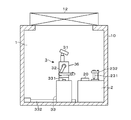
本発明の細胞培養加工設備は、筐体10によって外部雰囲気から区画された作業室1内に、細胞培養用の各種機器が配置された作業卓2と、この作業卓2と対向する位置に設けられ、前記機器の操作を実行するマニピュレータ3と、を備えている。
本発明の細胞培養加工設備は、筐体10によって外部雰囲気から区画された作業室1内に、細胞培養用の各種機器が配置された作業卓2と、この作業卓2と対向する位置に設けられ、前記機器の操作を実行するマニピュレータ3と、を備えている。
図1、図2に示すように作業卓2は、後述するマニピュレータ3のハンド32がアクセス可能な高さ位置に設けられている。図1には、細胞培養用の機器として、培養容器であるディッシュ26を収納するインキュベータ21、流体の吸引、供給操作を実行するピペット装置(吸引具)22、液体試料中に分散した細胞の分離操作を実行する遠心分離器23、及び作業卓2で培養され分離された目的細胞の大量培養を行う大量培養装置24を備えた作業卓2の例を示している。
インキュベータ21は、内部を一定温度に保つことが可能な筐体内に、多数のディッシュ26を収容可能な棚を備えている。図1にはマニピュレータ3側から見て、手前側及び奥手側の前後2列の棚を配置したインキュベータ21の例を示している。この場合には、手前の棚を昇降自在に構成することにより、各棚に収容されたディッシュ26に手前側からアクセスすることができる。
ピペット装置22は、ディッシュ26などの流体容器から液体試料や各種薬液を所定量だけ吸引し、別の容器へ注入する操作に用いられる。ピペット装置22は、例えば作業卓2の上面に配置されたスタンドに着脱自在に保持される。ピペット装置22を保持するスタンドの隣には、前記ピペット装置22に対して着脱自在に構成され、取り扱う流体に応じて交換される複数のピペットチップ221がチップスタンド222に保持されている。
遠心分離器23には、筐体内に収容された回転ロータのホルダー(不図示)に遠心管231を保持し、回転ロータを回転させて遠心管231内の液体試料に遠心力を加え、液体試料中の細胞の分離などを行う。遠心分離器23の隣には、遠心管231を保持する遠心管スタンド232が配置されている。
大量培養装置24は、例えば細胞のディッシュ26よりも大容量の培養液を収容可能な培養タンクや培養液の撹拌装置(不図示)などを備える。培養タンクは例えば作業卓2の下方側に配置され、作業室1の外部からアクセスして取り外すことができる(図1には培養タンクを破線で示してある)。例えば作業卓2の上面からは、ディッシュ26にて培養された目的細胞を培養タンク内に注入するための注入口241が突出している。なお、大量培養装置24には、培養フラスコ及びフラスコ用インキュベータが併設されているが、図1には記載を省略してある。
図1に示すように、マニピュレータ3から見て左手側の筐体10の側壁面には、外部との間で試料や薬液を収容した容器などを搬入出するための搬入出部11が設けられている。搬入出部11は、筐体10の側の壁面及び作業室1側に設けられた開閉扉111、112によって、外部空間及び作業室1内から区画自在に構成された空間であり、その内部には搬入出物を載置した状態で移動自在な搬入出ステージ113が設けられている。
さらに、マニピュレータ3側から見て、スタンドに保持されたピペット装置22や遠心管スタンド232の手前側の作業卓2上には作業ステージ20が設けられている。マニピュレータ3によって操作されるディッシュ26はこの作業ステージ20上に載置される。
また、前記作業卓2には、作業ステージ20、搬入出部11、及びインキュベータ21にアクセス自在に構成された搬送装置25が設けられている。搬送装置25は、作業ステージ20との搬入出部11との間の作業卓2上に設けられた走行レール251上を走行自在、鉛直軸周りに回転自在、及び昇降自在に構成されている。また搬送装置25は、ディッシュ26などの搬送対象物を保持する保持部252を備え、当該保持部252を伸縮させて、搬入出部11内の搬入出ステージ113やインキュベータ21内の各棚におけるディッシュ26の保持位置、及び作業ステージ20にアクセスすることができる。
さらに図2に示すように、作業室1を構成する筐体10の天井部には、不図示のファンから送られた気体(例えば作業室1の外部の空気)をろ過するフィルターユニット12が設けられている。また作業室1には、筐体10の内部の圧力を調節する不図示の排気ユニットが設けられている。
以上に説明したように、ディッシュ26内の液体試料などを吸引するピペット装置22やディッシュ26が収容されるインキュベータ21などの細胞培養用の機器は筐体10によって外部から隔離された作業室1内に設けられている。そして、これらの機器を用いた細胞培養に係る操作は、作業室1内に配置されたマニピュレータ3を用いて実行される。
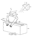
図3に示すように、本例のマニピュレータ3は、ボディ形状のハンド支持部36に、頭部31と、2本の腕状のハンド32とを設けた上半身を備え、遠隔操作によって動作するスレイブロボットとして構成されている。
ハンド支持部36の上端に設けられた頭部31は、例えば2つの3Dカメラ311を備え、遠隔操作により頭部31を上下、左右に動かすことにより、3Dカメラ311の向きを変えることができる。3Dカメラ311や頭部31は、本例の可動式撮像部に相当する。また頭部31には、作業室1内の音を検出するマイクロフォンが設けられている。
ハンド支持部36の上端に設けられた頭部31は、例えば2つの3Dカメラ311を備え、遠隔操作により頭部31を上下、左右に動かすことにより、3Dカメラ311の向きを変えることができる。3Dカメラ311や頭部31は、本例の可動式撮像部に相当する。また頭部31には、作業室1内の音を検出するマイクロフォンが設けられている。
各ハンド32は、複数の関節を有する腕部321と、この腕部321の先端に設けられた複数本、例えば3~5本の指部322とを備える。各指部322には複数の関節が設けられている。各関節を用いた腕部321及び指部322の動きは後述の遠隔操作により実行される。また各指部322には不図示の圧力センサが設けられ、ディッシュ26などを持ったときの触覚をオペレータPに対してフィードバックすることができる。このほか、腕部321の外側面には、作業室1内の機器との衝突を回避するために、これらの機器の近接を検出する近接センサを設けてもよい。
図1~図3に示すように、マニピュレータ3のハンド支持部36は、既述のインキュベータ21やピペット装置22などが配置された作業卓2に沿って、横方向に伸びる基台部33によって下面側から支持されている。基台部33の上面には走行レール331が設けられ、ハンド支持部36(マニピュレータ3)はこの走行レール331に沿って基台部33上を左右に移動することができる。
また、ハンド支持部36は、基台部33上で自在に水平旋回することもできる。
また、ハンド支持部36は、基台部33上で自在に水平旋回することもできる。
一方、基台部33の床面には、横長に形成された基台部33と直交する方向(前後方向)に向けて伸びる2本の走行レール332が設けられている。基台部33はこれらの走行レール332上に配置され、作業卓2に近づき、または遠ざかる方向へ移動することができる。なお、図3においては、当図に向かって左側部分の基台部33の記載を一部省略してある。
また基台部33には、マニピュレータ3が障害物に衝突した衝撃を検出したとき、基台部33の移動を自動停止するための衝突センサ、及び基台部33の駆動機構の制御部を設けてもよい。
また基台部33には、マニピュレータ3が障害物に衝突した衝撃を検出したとき、基台部33の移動を自動停止するための衝突センサ、及び基台部33の駆動機構の制御部を設けてもよい。
基台部33上に設けられたハンド支持部36の左右方向の移動動作や旋回動作、また基台部33の前後方向の移動動作は遠隔操作により実行される。
マニピュレータ3は、不図示の通信部を備え、作業室1内に配置されたスレイブ側制御部51との間で、頭部31、ハンド32、ハンド支持部36、基台部33の操作信号の受信、及び3Dカメラ311にて撮影した画像情報やマイクロフォンの音声情報、指部322にて検出した圧力情報の送信を行う。スレイブ側制御部51は、作業室1の外部の操作区域側に設けられた後述のマスタ側制御部52または自動制御部53との間で、これらの情報の入出力を行う(図3に示す「信号A、B」)。マニピュレータ3とスレイブ側制御部51との通信は、無線で行ってもよいし、有線で行ってもよい。
マニピュレータ3は、不図示の通信部を備え、作業室1内に配置されたスレイブ側制御部51との間で、頭部31、ハンド32、ハンド支持部36、基台部33の操作信号の受信、及び3Dカメラ311にて撮影した画像情報やマイクロフォンの音声情報、指部322にて検出した圧力情報の送信を行う。スレイブ側制御部51は、作業室1の外部の操作区域側に設けられた後述のマスタ側制御部52または自動制御部53との間で、これらの情報の入出力を行う(図3に示す「信号A、B」)。マニピュレータ3とスレイブ側制御部51との通信は、無線で行ってもよいし、有線で行ってもよい。
さらにマニピュレータ3は、マスタ側制御部52を介したオペレータPによる遠隔操作(マニュアル操作)と、予め記憶されたティーチングデータに基づく自動操作とを切り替えて実行することができる。
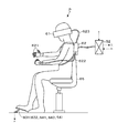
初めに図4、図5を参照しながら、オペレータPによるマニュアル操作を行うマスタシステムについて説明を行う。当該マスタシステムが設けられるマニピュレータ3の操作区域は、作業室1の外部であれば特段の限定はないが、例えば作業室1が配置されている建屋内に設けられる。
初めに図4、図5を参照しながら、オペレータPによるマニュアル操作を行うマスタシステムについて説明を行う。当該マスタシステムが設けられるマニピュレータ3の操作区域は、作業室1の外部であれば特段の限定はないが、例えば作業室1が配置されている建屋内に設けられる。
本例のマスタシステムは、マニピュレータ3の遠隔操作を行うオペレータPの頭部に装着されるヘッドギア部61と、ヘッドギア部61の位置や向きを検出する頭部リンク機構623と、オペレータPの両手の指に装着され、各指の位置や向きを検出する指部リンク機構621と、オペレータPの手に装着され、オペレータPの腕の位置や向きを検出する腕部リンク機構622と、を備える。頭部リンク機構623、指部リンク機構621、腕部リンク機構622は、オペレータPの体幹(例えば背中)に装着され、マニピュレータ3における頭部31やハンド32(腕部321、指部322)の位置や向きを教示する情報の検出及び出力を行う入出力部62に接続されている。
オペレータPの身体の動作を頭部リンク機構623、指部リンク機構621、腕部リンク機構622(多関節構造体)の形状変化に伴う関節の変化量として検出し、マニピュレータ3の遠隔操作を行うための教示情報(操作信号)として出力する手法としては既存のシステムを利用することができる。
頭部リンク機構623を用いて検出されたヘッドギア部61の向きは、頭部31の向きを変える操作信号として入力され、オペレータPの頭部の動きに連動してマニピュレータ3の頭部31が動くこととなる。さらに、オペレータPには、当該上半身の鉛直軸周りのひねりを検出する不図示の上半身リンク機構が設けられ、オペレータPの上半身をひねると、そのひねり方向へ向けてハンド支持部36を水平旋回させることができる。その後、オペレータPの上半身のひねりを戻すと、ハンド支持部36の旋回が停止する。
さらにヘッドギア部61には、マニピュレータ3の3Dカメラ311にて撮影した映像を表示する3Dモニタが設けられており、オペレータPはこの3Dモニタを介して作業室1内の様子を視認することができる。
さらにヘッドギア部61には、マニピュレータ3の3Dカメラ311にて撮影した映像を表示する3Dモニタが設けられており、オペレータPはこの3Dモニタを介して作業室1内の様子を視認することができる。
同様に、指部リンク機構621、腕部リンク機構622を用いて検出されたオペレータPの腕や指の位置や向きは、ハンド32の操作信号として入力され、オペレータPの腕や指の動きに連動してマニピュレータ3のハンド32が動くこととなる。また、マニピュレータ3側の指部322の圧力センサにて検出された圧力情報は、例えばハンド32によってディッシュ26を保持する操作の触覚情報としてオペレータPが装着するグローブに伝達される。
さらに図4、図5に示すように、本例マスタシステムは、マニピュレータ3の遠隔操作を行うオペレータPが着座する作業椅子65と、当該作業椅子65に着座したオペレータPの足下の床面に配置された各種の操作ペダル631、632、641、642とを備える。
作業椅子65に着座したオペレータPの右足側の足下には、基台部33を前進移動させるための前進ペダル631、後退移動させるための後退ペダル632が設けられている。一方、オペレータPの左足側の足下には、基台部33上のハンド支持部36を右方向へ移動させるための右移動ペダル641、左方向へ移動させるための左移動ペダル642が設けられている。これら各操作ペダル631、632、641、642が踏まれている期間中に、対応する各種動作が実行される。また、これらの操作ペダル631、632、641、642の踏み込み量に応じて、基台部33、ハンド支持部36の移動速度を変化させることできるように構成してもよい。
頭部リンク機構623、指部リンク機構621、腕部リンク機構622から取得された頭部31やハンド32の教示情報は、入出力部62を介して操作区域内に配置されたマスタ側制御部52に入力される。また、不図示の上半身リンク機構から出力されたオペレータPの上半身のひねりに関する情報や各操作ペダル631、632、641、642の操作情報も前記マスタ側制御部52に入力される。これらの情報は、マニピュレータ3を遠隔操作するための操作信号として作業室1側のスレイブ側制御部51に出力される。また、スレイブ側制御部51から取得した画像情報や音声情報、圧力情報についてもマスタ側制御部52を介して、オペレータPが装着しているヘッドギア部61やグローブに送信される。
ここで、既述の頭部リンク機構623、指部リンク機構621、腕部リンク機構622、上半身リンク機構(不図示)や入出力部62、各種操作ペダル631、632、641、642は、マニピュレータ3にオペレータPの動きを伝え、細胞培養用の機器の操作を実行するための操作部に相当している。
以上に説明したマスタシステムを介して遠隔操作(マニュアル操作)されるマニピュレータ3は、当該マニュアル操作により実行された操作の動作データ(操作を実行している期間中における、各時刻の頭部31、ハンド支持部36、ハンド32(腕部321及び指部322)や基台部33の位置データや、位置データで特定される各位置における移動速度データ、ディッシュ26、ピペット装置22に加える力に係る圧力データなど)をティーチングデータとして記憶しておくことにより、当該ティーチングデータに基づいて細胞培養用の機器の操作を自動で実行することもできる。
この結果、事前に熟練者が既述のマスタシステムを利用してマニピュレータ3のマニュアル操作を実行し、そのときのマニピュレータ3の動作データをティーチングデータとして利用することにより、熟練者の技量を自動で再現することが可能となる。
この結果、事前に熟練者が既述のマスタシステムを利用してマニピュレータ3のマニュアル操作を実行し、そのときのマニピュレータ3の動作データをティーチングデータとして利用することにより、熟練者の技量を自動で再現することが可能となる。
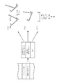
上述のティーチングデータを取得するため、図6に示すように本例の細胞培養加工設備は、マニピュレータ3による細胞培養用の機器の操作を自動で実行させるための制御部(自動制御部53)と、マスタシステムを利用したマニュアル操作の有効状態/無効状態の切り替えを行う切替部54と、ティーチングデータの記憶や自動操作の実行に係るオペレータPからの指示を受け付けるタッチパネル7とを備えている。
なお説明の便宜上、図6には自動制御部53と、既述のスレイブ側制御部51、マスタ側制御部52とを含む制御部50の全体を総括的に表示してある。
なお説明の便宜上、図6には自動制御部53と、既述のスレイブ側制御部51、マスタ側制御部52とを含む制御部50の全体を総括的に表示してある。
制御部50は、不図示のCPU(Central Processing Unit)とメモリ(記憶部)501とを備えたコンピュータとして構成され、メモリ501にはマニピュレータ3の自動操作を実行するためのティーチングデータが記憶される。ティーチングデータは、例えば細胞培養用の各機器の操作毎に、あるいは操作のグループ毎に制御部50のメモリ501に記憶される。
ここで実際には既述のように、スレイブ側制御部51とマスタ側制御部52とは別々のコンピュータとして構成され、スレイブ側制御部51は作業室内に配置される一方、マスタ側制御部52はオペレータPがいる操作区域側に配置される。
また、自動制御部53は、スレイブ側制御部51及びマスタ側制御部52を利用したマニュアル操作と切り替えて、前記ティーチングデータに基づくマニピュレータ3の自動操作を実行する役割を果たす。例えば自動制御部53は、スレイブ側制御部51と共通のコンピュータにより構成される。
また、自動制御部53は、スレイブ側制御部51及びマスタ側制御部52を利用したマニュアル操作と切り替えて、前記ティーチングデータに基づくマニピュレータ3の自動操作を実行する役割を果たす。例えば自動制御部53は、スレイブ側制御部51と共通のコンピュータにより構成される。
各ティーチングデータに基づいて実行される自動操作は、初期状態から始まり、一連の操作の実行後、終了状態となって終わる。初期状態とは、例えばマニピュレータ3のハンド32が何も持たず、ハンド支持部36の前方に左右のハンド32を揃えた状態とされる。また終了状態は例えば初期状態と同じ状態に設定される。初期状態(終了状態)は、ハンド32のいわば原点位置に設定される。
ここでは、細胞培養にて実施される、プロトコールに記載された一連の操作のうち、例えば一部の操作についてのみティーチングデータを利用した自動操作に切り替えて実行する場合について説明する。このとき、マニピュレータ3のマニュアル操作を行った後、次の操作を自動操作で行う場合には、マニピュレータ3のハンド32は先行する操作の終了状態から、先ず初期状態になり、この初期状態から次の操作が始まり、終了状態(初期状態と同じ状態)になる。更に次の操作をマニュアル操作で行う場合には、この終了状態から作業が始まることになる。即ち、ティーチングデータは、ハンド32が初期状態から始まって同じ状態に戻るまでの動作データとして構成される。
既述のように、マニュアル操作は、ハンド32側の指部322にて検出された圧力情報が、触覚情報としてオペレータPのグローブに伝達された結果を反映しながら実行されている。このため、当該動作データも、この触覚情報がフィードバックされた結果を踏まえたものとなっており、オペレータPが触覚情報に基づいてマニュアル操作を行った結果として得られた繊細な動作が記憶されている。
また既述のように作業室1内におけるハンド32による操作は、ハンド支持部36の上端に設けられた頭部31に搭載された可動式の3Dカメラ311にて撮像することができる。オペレータPは、頭部に装着されたヘッドギア部61の3Dモニタにより、3Dカメラ311からの画像を見ることができる。
例えばティーチングデータは、自動操作の対象となる被操作物(操作の対称)の状態毎に複数用意される。このためオペレータPは、自動操作が行われるときに、3Dカメラ311の撮像画像に対応するティーチングデータ、詳しくは3Dカメラ311の撮像画像から認識される被操作物の状態に対応するティーチングデータを、タッチパネル7に表示された画面を介して選択することができる。例えばヘッドギア部61の3Dモニタは、半透明、または視線を下げた領域の視野が透明になっていて、3Dモニタの画像、及びタッチパネル7に表示された画面の双方を視認することができる。
被操作物の状態に応じて用意されるティーチングデータは、被操作物の状態(例えばディッシュ26内の細胞塊の大きさや液体試料中の細胞の分散の状態)にばらつき傾向があるとき、当該ばらつきの状態に各々対応付けられた操作を実施できるように、事前に複数用意される。
ここで自動操作の途中で複数のティーチングデータの中から実行する操作を選択する手法として、3Dカメラ311の撮像画像の認識結果に基づいて、例えばマニピュレータ3の自動操作を行う自動制御部53が、画像マッチングなどにより被操作物の状態に応じたティーチングデータを選択してもよい。この場合には、自動制御部53がティーチングデータDn(n=1、2、…)の自動選択用の選択部を構成していることになる。
また、当該ティーチングデータを選択するタイミングとなったら、マニピュレータ3の自動操作を停止し、オペレータPが3Dモニタの画像を確認した結果に基づきタッチパネル7の操作画面からティーチングデータを選択する構成としてもよい。また、画像マッチングなどの自動判定が容易か否かに応じて、オペレータPがティーチングデータを選択する手法と、自動制御部53がティーチングデータを選択する手法とを使い分けてもよい。
従ってマニピュレータ3の自動操作において、3Dカメラ311の撮像画像は、オペレータP自身がティーチングデータを選択するとき、あるいは自動制御部53が自動でティーチングデータを選択するときに使用される。
従ってマニピュレータ3の自動操作において、3Dカメラ311の撮像画像は、オペレータP自身がティーチングデータを選択するとき、あるいは自動制御部53が自動でティーチングデータを選択するときに使用される。
さらに図6に示すように、自動制御部53には、マニュアル操作の有効状態/無効状態の切り替えを実行する切替部54が接続されている。例えば切替部54は、オペレータPの足元であって、既述の前進、後退ペダル631、632の外方側に設けられたペダルとして構成される(図4)。このとき、切替部54を構成するペダルは、一度、踏み込むとペダルが下がった状態を維持するストッパを備え、再度、踏み込むと元の位置に戻る構成となっている。こうして、ペダルが下がった状態と、元の位置に戻った状態とを切り替えることにより、マニュアル操作の有効状態/無効状態が切り替えられる。
以上に説明した構成を備える細胞培養加工設備の動作について説明する。
以下、ディッシュ26内の培地に播種された目的細胞をインキュベータ21内で培養した後、当該目的細胞をディッシュ26から剥がして細胞浮遊液を調製し、新たなディッシュ26に播種する継代工程に含まれる操作を例に挙げて説明を行う。
以下、ディッシュ26内の培地に播種された目的細胞をインキュベータ21内で培養した後、当該目的細胞をディッシュ26から剥がして細胞浮遊液を調製し、新たなディッシュ26に播種する継代工程に含まれる操作を例に挙げて説明を行う。
具体例として、目的細胞を培養したディッシュ26にトリプシンを添加した後、再度、インキュベータ21内で所定時間保持したディッシュ26について、ディッシュ26の底面から剥がれた目的細胞を採取して、新たなディッシュ26内に播種する操作について説明する。
この操作において、オペレータPによるマニピュレータ3のマニュアル操作時にティーチングデータを蓄積する動作と、このティーチングデータを用いて自動操作を実行する動作について順次、説明する。
この操作において、オペレータPによるマニピュレータ3のマニュアル操作時にティーチングデータを蓄積する動作と、このティーチングデータを用いて自動操作を実行する動作について順次、説明する。
(ティーチングデータの蓄積)
オペレータPは、ヘッドギア部61やグローブ、入出力部62を装着して作業椅子65に着座し、マニュアル操作が有効な状態に切替部54を切り替え、マニピュレータ3のマニュアル操作を開始する。ティーチングデータとして記憶される操作を実行するオペレータPとしては、例えば当該操作について熟練した作業者が選任される。
オペレータPは、ヘッドギア部61やグローブ、入出力部62を装着して作業椅子65に着座し、マニュアル操作が有効な状態に切替部54を切り替え、マニピュレータ3のマニュアル操作を開始する。ティーチングデータとして記憶される操作を実行するオペレータPとしては、例えば当該操作について熟練した作業者が選任される。
初めに、搬送装置25が、トリプシンの添加後、インキュベータ21内で所定時間保持されたディッシュ26aを取り出して、搬送し、作業ステージ20上へ載置する。次いで、ティーチングデータの記憶を開始する前に、3Dカメラ311を介してディッシュ26aの画像を撮像し、ディッシュ26aにおける細胞の分散状態に関する情報をマスタ側制御部52に記憶する。この動作においては、例えば作業ステージ20上のディッシュ26aを持ち上げてから傾け、ディッシュ26aの底面に付着している細胞の付着状態も撮像する。
ここで細胞の分散状態に関する情報として、分散の度合いをn種類の分類情報(例えば「良好」、「やや良好」、「悪い」など)から選択して前記画像データとの対応付けを行うことができる。分類情報の対応付けは、例えばオペレータPの経験に基づいて行われる。これによりこれから取得されるティーチングデータとディッシュ26a内の細胞の分散状態の画像データとが分類情報を介して対応付けられ、メモリ501に記憶される。
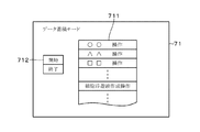
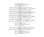
次いでオペレータPは、ディッシュ26aを作業ステージ20上に載置し、マニピュレータ3のハンド32を初期状態の位置に移動させる(図10のステップS11)。しかる後、オペレータPは切替部54によりマニピュレータ3のマニュアル操作を無効状態に切り替える(ステップS12)。次いで、オペレータPは、タッチパネル7に表示されたデータ蓄積操作選択画面71のデータ蓄積メニュー711の中から、「細胞浮遊液作成操作」を選択し、開始/終了切替ボタン712の「開始」を押す(ステップS13、図8)。続いてオペレータPは切替部54によりマニピュレータ3のマニュアル操作を有効状態に切り替え(ステップS14)、初期状態の位置で待機しているマニピュレータ3に対し、細胞浮遊液作成操作に係る一連のマニュアル操作を実行する(ステップS15)。
具体的には、ピペット装置22に所定のピペットチップ221を取り付けた後、当該ピペット装置22を右手側のハンド32にて掴み、所定の薬液容器の中から細胞分散用の培養液を吸引し、新しい2つのディッシュ26b、26cに所定量の培養液を分ける準備操作を行う。
次いで、作業ステージ20上に載置されている、トリプシン処理後のディッシュ26を左手で把持し、ピペット装置22によってディッシュ22b内の培養液を吸引してからディッシュ26a内に注入する。このときディッシュ26aを傾けて底部に付着している細胞を剥離させるようにピペット装置22を操作する。
次いで、作業ステージ20上に載置されている、トリプシン処理後のディッシュ26を左手で把持し、ピペット装置22によってディッシュ22b内の培養液を吸引してからディッシュ26a内に注入する。このときディッシュ26aを傾けて底部に付着している細胞を剥離させるようにピペット装置22を操作する。
さらに、傾いているディッシュ26の下部に溜まった細胞浮遊液を再度ピペット装置22にて吸引し、傾けたディッシュ26の底部の高い部位(液の無い面)に注入して細胞の剥離を更に行う(図7(a))。このような操作を複数回、繰り返した後、細胞浮遊液を希釈するための培養液が入った既述のディッシュ26cからピペット装置22で培養液を吸引し、ディッシュ26a内に注入する(図7(b))。
しかる後、ピペット装置22をスタンドに戻し、続いてディッシュ26aを動かして液を撹拌する。ディッシュ26aの動かし方は、例えば時計回りに複数回公転させ、次いで反時計回りに複数回公転させ、更に左右に複数回振り、最後に上下に複数回揺らす(図7(c))。
その後、ディッシュ26aを作業ステージ20上に載置すると、ディッシュ26aは搬送装置25によってインキュベータ21内へ搬送される。オペレータPは、マニピュレータ3のハンド32を終了状態に設定する。終了状態は例えば初期状態と同じ状態である。しかる後、オペレータPは切替部54によりマニピュレータ3のマニュアル操作を無効状態に切り替え、データ蓄積操作選択画面71を介して開始/終了切替ボタン712の「終了」ボタンを押す。この結果、目的細胞の継代工程に係る重要な操作の動作データがティーチングデータとしてメモリ501に記憶される。
(自動操作への切り替え)
例えば非熟練の作業者であるオペレータPは、マスタシステムを利用してマニピュレータ3のマニュアル操作を行い、搬送装置25によってインキュベータ21から取り出され、作業ステージ20上に載置されたトリプシン処理後のディッシュ26aを取り上げる。そして、3Dカメラ311によりディッシュ26aの画像を撮像し、ディッシュ26aにおける細胞の分散状態に関する情報を取得後、作業ステージ20上にディッシュ26aを再び載置する。
例えば非熟練の作業者であるオペレータPは、マスタシステムを利用してマニピュレータ3のマニュアル操作を行い、搬送装置25によってインキュベータ21から取り出され、作業ステージ20上に載置されたトリプシン処理後のディッシュ26aを取り上げる。そして、3Dカメラ311によりディッシュ26aの画像を撮像し、ディッシュ26aにおける細胞の分散状態に関する情報を取得後、作業ステージ20上にディッシュ26aを再び載置する。
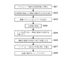
次いでオペレータPは、切替部54によりマニピュレータ3のマニュアル操作を無効状態に切り替え(図11のステップS21)、タッチパネル7に表示された自動操作選択画面72を介して操作選択ボタン721中の「細胞浮遊液作成操作」を選択する(ステップS22、図9)。また、ヘッドギア部61の3Dモニタに写し出されたディッシュ26aの画像に基づき、自動操作選択画面72に続いて表示されるパターン選択画面73のパターン選択ボタン731からディッシュ26a内の細胞の分散状態(パターンPn)に応じたデータ(ティーチングデータDn)を選択する(ステップS23、図9)。ここで、図9のパターン選択画面73には、三種類のパターンP1~P3に対応して、ティーチングデータD1~D3を選択可能とした例を示してある。なお、既述のように、ティーチングデータDnは、画像マッチングなどにより、自動制御部53が自動的に選択を行ってもよい。
その後、タッチパネル7に映し出される自動操作選択画面72の開始/終了切替ボタン722にて「開始」を押すと、選択したティーチングデータDnが読み出され、読み出されたティーチングデータに基づきマニピュレータ3が自動操作を実行する(ステップS24)。
即ち、マニピュレータ3は先ず細胞浮遊液作成操作を行う前の初期状態になる。そして、マニピュレータ3はティーチングデータの蓄積時に実行した熟練者による一連の細胞浮遊液作成操作を再現する(ステップS25)。
即ち、マニピュレータ3は先ず細胞浮遊液作成操作を行う前の初期状態になる。そして、マニピュレータ3はティーチングデータの蓄積時に実行した熟練者による一連の細胞浮遊液作成操作を再現する(ステップS25)。
しかる後、細胞浮遊液作成操作が終了すると、マニピュレータ3は終了状態になる(ステップS26)。本例では、オペレータPは切替部54によりマニピュレータ3のマニュアル操作を有効状態に切り替え(ステップS27)、後続の操作をマニュアル操作により実行する(ステップS28)。
ここで、細胞浮遊液作成操作を再現するステップS25において、ディッシュ26aの細胞を剥離する操作を繰り返し行う際には(図7(a))、3Dモニタに写し出されたディッシュ26aの画像に基づき、パターン選択画面73のパターン選択ボタン731からディッシュ26a内の細胞の分散状態(パターンPn)に応じたデータ(ティーチングデータDn)の選択を繰り返しの度に行ってもよい。この場合は、例えば当該繰り返し操作における所定の状態、例えば、一旦、ディッシュ26aからピペット装置22を少し離した状態を初期状態とし、剥離操作終了後、再度、同じ位置にピペット装置22を移動させた状態を終了状態とする。しかる後、ディッシュ26aの画像に基づき、繰り返し細胞の剥離操作を実行するか、これに続く細胞浮遊液の希釈操作を実行するかを選択する。
本実施の形態に係る細胞培養加工設備によれば以下の効果がある。作業室1の外部に設けられ、オペレータPの動きを伝える操作部(頭部リンク機構623、指部リンク機構621、腕部リンク機構622、上半身リンク機構(不図示)や入出力部62、各種操作ペダル631、632、641、642)により、作業室1内に設けられたマニピュレータ3による細胞培養用のディッシュ26及びインキュベータ21の少なくとも一方の操作を実行したとき、当該マニピュレータ3の動作データをティーチングデータとして記憶するので、前記操作を自動で制御することが可能となる。
また、マニピュレータ3を介して作業室1内の操作を実行することにより、通常、ヒトが立ち入る空間では実行しにくい強力な殺菌操作、作業室1全体の薬剤による殺菌処理などを行うこともできる。
さらに、最大の汚染源であるヒトによる直接操作がないため、確実な微生物汚染防止を図ることもできる。
さらに、最大の汚染源であるヒトによる直接操作がないため、確実な微生物汚染防止を図ることもできる。
ここで上述の実施の形態では、目的細胞の継代工程における一部の操作を例示して、ティーチングデータを蓄積する手法や、蓄積されたティーチングデータによりマニピュレータ3の自動操作を実行する動作の説明を行った。
但し、ティーチングデータの蓄積、及びこれに基づき自動に実行される操作の対象は、例示の操作に限定されるものではないことは勿論である。
但し、ティーチングデータの蓄積、及びこれに基づき自動に実行される操作の対象は、例示の操作に限定されるものではないことは勿論である。
例えば「ディッシュ26内の培地を蓋に触れないように振る」、「蓋だけでなく、ディッシュ26の本体に指が触れていることを確認しながらディッシュ26を持ち上げる」、「ディッシュ26の側面や底面にピペットチップ221を触れさせずに細胞浮遊液を吸引する」、「ディッシュ26を回転させずに前後左右に振りながら、ディッシュ26の全体に均一に細胞浮遊液を分散させる」、「ピペットチップ221の先端を、液面のごく近傍に位置させて、遠心管231内の液体を吸引する」、「ピペット装置22にて吸引した細胞浮遊液をなるべく早く複数のディッシュ26に分ける」などといった、熟練者の経験を必要とする各種操作について、ティーチングデータを蓄積しておくことにより、プロトコールに記載することが難しい熟練者の操作を自動で実行することができる。
また、ティーチングデータを蓄積する手法についても、オペレータPによるマニピュレータ3の1回のマニュアル操作を記憶する場合に限定ない。例えば、対象となる一連の操作を繰り返し実行して毎回の動作データを記憶し、これらの操作に含まれる個別の操作に係る動作データの中から、最も良好な操作を選定し、各個別操作の動作データを繋ぎ合わせてティーチングデータを構成してもよい。
この他、対象となる一連の操作を繰り返し実行して複数の動作データを取得し、これらの動作データに含まれる位置データや圧力データなどの平均値に基づいて実現されるマニピュレータ3の平均的な動作をティーチングデータとしてもよい。
さらに、本例の細胞培養加工設備で培養される細胞は、ヒト細胞に限定されるものではなく、動物細胞や植物細胞、単細胞生物の細胞であってもよい。
P オペレータ
1 作業室
2 作業卓
21 インキュベータ
22 ピペット装置
26 ディッシュ
3 マニピュレータ
311 3Dカメラ
32 ハンド
51 スレイブ側制御部
52 マスタ側制御部
53 自動制御部
501 メモリ
54 切替部
61 ヘッドギア部
621 指部リンク機構
622 腕部リンク機構
623 頭部リンク機構
631 前進ペダル
632 後退ペダル
641 右移動ペダル
642 左移動ペダル
7 タッチパネル
1 作業室
2 作業卓
21 インキュベータ
22 ピペット装置
26 ディッシュ
3 マニピュレータ
311 3Dカメラ
32 ハンド
51 スレイブ側制御部
52 マスタ側制御部
53 自動制御部
501 メモリ
54 切替部
61 ヘッドギア部
621 指部リンク機構
622 腕部リンク機構
623 頭部リンク機構
631 前進ペダル
632 後退ペダル
641 右移動ペダル
642 左移動ペダル
7 タッチパネル
Claims (6)
- 細胞培養用の培養容器及び当該培養容器内の流体を吸引する吸引具と、前記培養容器が収納されるインキュベータと、を備えた作業室と、
前記培養容器に対する操作及び前記吸引具に対する操作の各々について遠隔操作されると共に可動式撮像部及び触覚機能を搭載し、前記作業室内に設けられたマニピュレータと、
前記作業室の外に設けられ、オペレータの動きを伝える操作部により、前記培養容器及び前記吸引具の少なくとも一方に対する操作がマニピュレータにより実行されたときの当該マニピュレータの動作データをティーチングデータとして記憶する記憶部と、
前記ティーチングデータを読み出して前記マニピュレータに前記培養容器及び前記吸引具の少なくとも一方の操作を自動で実行させるための制御部と、を備えたことを特徴とする細胞培養加工設備。 - 前記ティーチングデータは、前記培養容器及び前記吸引具の少なくとも一方に対する操作の対象の状態に応じて複数用意され、
複数の前記ティーチングデータの中から、前記マニピュレータに装着されている前記可動式撮像部により得られた画像に基づいて選択されたティーチングデータが用いられることを特徴とする請求項1記載の細胞培養加工設備。 - 前記可動式撮像部にて得られた画像に基づいて、前記複数のティーチングデータの中から、使用するティーチングデータをオペレータが選択するためのマニュアル選択用の選択部を備えたことを特徴とする請求項2記載の細胞培養加工設備。
- 前記制御部は、前記可動式撮像部にて得られた画像に基づいて、前記複数のティーチングデータの中から、使用するティーチングデータを自動で選択するための自動選択用の選択部を備えたことを特徴とする請求項2記載の細胞培養加工設備。
- 前記遠隔操作に対してオペレータの動きを「有効」とするか「無効」とするかを切り替える切替部を備え、
前記切替部により「無効」に切り替えられた後、前記制御部は、前記メモリから読み出されたティーチングデータに基づいて、前記マニピュレータが予め決められた初期状態から前記操作を自動で実行するように構成されていることを特徴とする請求項1記載の細胞培養加工設備。 - 前記制御部は、前記マニピュレータが前記操作を自動で実行した後、前記初期状態に戻るように構成されていることを特徴とする請求項5記載の細胞培養加工設備。
Priority Applications (2)
| Application Number | Priority Date | Filing Date | Title |
|---|---|---|---|
| PCT/JP2015/000802 WO2016132398A1 (ja) | 2015-02-19 | 2015-02-19 | 細胞培養加工設備 |
| JP2017500474A JP6472868B2 (ja) | 2015-02-19 | 2015-02-19 | 細胞培養加工設備 |
Applications Claiming Priority (1)
| Application Number | Priority Date | Filing Date | Title |
|---|---|---|---|
| PCT/JP2015/000802 WO2016132398A1 (ja) | 2015-02-19 | 2015-02-19 | 細胞培養加工設備 |
Publications (1)
| Publication Number | Publication Date |
|---|---|
| WO2016132398A1 true WO2016132398A1 (ja) | 2016-08-25 |
Family
ID=56688814
Family Applications (1)
| Application Number | Title | Priority Date | Filing Date |
|---|---|---|---|
| PCT/JP2015/000802 Ceased WO2016132398A1 (ja) | 2015-02-19 | 2015-02-19 | 細胞培養加工設備 |
Country Status (2)
| Country | Link |
|---|---|
| JP (1) | JP6472868B2 (ja) |
| WO (1) | WO2016132398A1 (ja) |
Cited By (10)
| Publication number | Priority date | Publication date | Assignee | Title |
|---|---|---|---|---|
| WO2019202900A1 (ja) * | 2018-04-15 | 2019-10-24 | 国立大学法人埼玉大学 | 行動推定装置、行動推定方法、および行動推定プログラム |
| WO2020194392A1 (ja) * | 2019-03-22 | 2020-10-01 | connectome.design株式会社 | 自律型ロボット用教師データ生成コンピュータ、方法及びプログラム |
| JP2021100401A (ja) * | 2019-12-24 | 2021-07-08 | 日本光電工業株式会社 | 細胞培養評価システム |
| JP2021185749A (ja) * | 2020-05-25 | 2021-12-13 | パナソニックIpマネジメント株式会社 | 細胞培養装置および細胞培養方法 |
| JP2022120356A (ja) * | 2021-02-05 | 2022-08-18 | 大成建設株式会社 | 遠隔操作ピペット装置及びピペットのロボットアームへの取付け構造 |
| JP2023046803A (ja) * | 2021-09-24 | 2023-04-05 | 国立大学法人 東京大学 | ロボットシステム |
| JP2023112867A (ja) * | 2022-02-02 | 2023-08-15 | セイコーエプソン株式会社 | 生成方法、コンピュータープログラム、および、生成システム |
| WO2024101438A1 (ja) * | 2022-11-09 | 2024-05-16 | オムロン株式会社 | ロボットシステム |
| WO2024101437A1 (ja) * | 2022-11-09 | 2024-05-16 | オムロン株式会社 | ロボットシステム |
| US12515322B2 (en) | 2020-07-14 | 2026-01-06 | University Of Tsukuba | Information processing device, method, and program |
Families Citing this family (1)
| Publication number | Priority date | Publication date | Assignee | Title |
|---|---|---|---|---|
| EP4166288A1 (en) * | 2021-10-13 | 2023-04-19 | Project Management Limited | A prefabricated automated unmanned and gloveless cleanroom processing enclosure |
Citations (7)
| Publication number | Priority date | Publication date | Assignee | Title |
|---|---|---|---|---|
| JPH0976063A (ja) * | 1995-09-16 | 1997-03-25 | Sanshiyuuzen Kogyo Kk | 溶接装置 |
| US6016385A (en) * | 1997-08-11 | 2000-01-18 | Fanu America Corp | Real time remotely controlled robot |
| JP2003340674A (ja) * | 2002-05-30 | 2003-12-02 | Mitsubishi Heavy Ind Ltd | 工作機械、及びそのティーチング方法 |
| JP2005334998A (ja) * | 2004-05-25 | 2005-12-08 | Fuji Photo Film Co Ltd | 自走式ロボットハンド、および、そのカメラ調整方法、ハンド移動量補正方法、ハンド調整方法 |
| JP2006149268A (ja) * | 2004-11-29 | 2006-06-15 | Kawasaki Heavy Ind Ltd | 多関節型ロボットを備えた自動細胞培養装置 |
| JP2009291104A (ja) * | 2008-06-04 | 2009-12-17 | Kawasaki Heavy Ind Ltd | 自動細胞培養装置 |
| JP2010089222A (ja) * | 2008-10-09 | 2010-04-22 | Hitachi Engineering & Services Co Ltd | 作業ロボットと、ティーチング方法 |
-
2015
- 2015-02-19 WO PCT/JP2015/000802 patent/WO2016132398A1/ja not_active Ceased
- 2015-02-19 JP JP2017500474A patent/JP6472868B2/ja active Active
Patent Citations (7)
| Publication number | Priority date | Publication date | Assignee | Title |
|---|---|---|---|---|
| JPH0976063A (ja) * | 1995-09-16 | 1997-03-25 | Sanshiyuuzen Kogyo Kk | 溶接装置 |
| US6016385A (en) * | 1997-08-11 | 2000-01-18 | Fanu America Corp | Real time remotely controlled robot |
| JP2003340674A (ja) * | 2002-05-30 | 2003-12-02 | Mitsubishi Heavy Ind Ltd | 工作機械、及びそのティーチング方法 |
| JP2005334998A (ja) * | 2004-05-25 | 2005-12-08 | Fuji Photo Film Co Ltd | 自走式ロボットハンド、および、そのカメラ調整方法、ハンド移動量補正方法、ハンド調整方法 |
| JP2006149268A (ja) * | 2004-11-29 | 2006-06-15 | Kawasaki Heavy Ind Ltd | 多関節型ロボットを備えた自動細胞培養装置 |
| JP2009291104A (ja) * | 2008-06-04 | 2009-12-17 | Kawasaki Heavy Ind Ltd | 自動細胞培養装置 |
| JP2010089222A (ja) * | 2008-10-09 | 2010-04-22 | Hitachi Engineering & Services Co Ltd | 作業ロボットと、ティーチング方法 |
Cited By (17)
| Publication number | Priority date | Publication date | Assignee | Title |
|---|---|---|---|---|
| US11787037B2 (en) | 2018-04-15 | 2023-10-17 | University Of Tsukuba | Behavior estimation apparatus, behavior estimation method, and behavior estimation program |
| JPWO2019202900A1 (ja) * | 2018-04-15 | 2021-04-22 | 国立大学法人 筑波大学 | 行動推定装置、行動推定方法、および行動推定プログラム |
| JP7246751B2 (ja) | 2018-04-15 | 2023-03-28 | 国立大学法人 筑波大学 | 行動推定装置、行動推定方法、および行動推定プログラム |
| WO2019202900A1 (ja) * | 2018-04-15 | 2019-10-24 | 国立大学法人埼玉大学 | 行動推定装置、行動推定方法、および行動推定プログラム |
| WO2020194392A1 (ja) * | 2019-03-22 | 2020-10-01 | connectome.design株式会社 | 自律型ロボット用教師データ生成コンピュータ、方法及びプログラム |
| JP2021100401A (ja) * | 2019-12-24 | 2021-07-08 | 日本光電工業株式会社 | 細胞培養評価システム |
| US12612590B2 (en) | 2019-12-24 | 2026-04-28 | Nihon Kohden Corporation | Cell culture evaluation system |
| JP7611541B2 (ja) | 2019-12-24 | 2025-01-10 | 日本光電工業株式会社 | 細胞培養評価システム |
| JP7486160B2 (ja) | 2020-05-25 | 2024-05-17 | パナソニックIpマネジメント株式会社 | 細胞培養装置および細胞培養方法 |
| JP2021185749A (ja) * | 2020-05-25 | 2021-12-13 | パナソニックIpマネジメント株式会社 | 細胞培養装置および細胞培養方法 |
| US12515322B2 (en) | 2020-07-14 | 2026-01-06 | University Of Tsukuba | Information processing device, method, and program |
| JP7576267B2 (ja) | 2021-02-05 | 2024-10-31 | 大成建設株式会社 | 遠隔操作ピペット装置及びピペットのロボットアームへの取付け構造 |
| JP2022120356A (ja) * | 2021-02-05 | 2022-08-18 | 大成建設株式会社 | 遠隔操作ピペット装置及びピペットのロボットアームへの取付け構造 |
| JP2023046803A (ja) * | 2021-09-24 | 2023-04-05 | 国立大学法人 東京大学 | ロボットシステム |
| JP2023112867A (ja) * | 2022-02-02 | 2023-08-15 | セイコーエプソン株式会社 | 生成方法、コンピュータープログラム、および、生成システム |
| WO2024101438A1 (ja) * | 2022-11-09 | 2024-05-16 | オムロン株式会社 | ロボットシステム |
| WO2024101437A1 (ja) * | 2022-11-09 | 2024-05-16 | オムロン株式会社 | ロボットシステム |
Also Published As
| Publication number | Publication date |
|---|---|
| JP6472868B2 (ja) | 2019-02-20 |
| JPWO2016132398A1 (ja) | 2017-11-30 |
Similar Documents
| Publication | Publication Date | Title |
|---|---|---|
| JP6472868B2 (ja) | 細胞培養加工設備 | |
| US11261412B2 (en) | Liquid transport method | |
| JP6545459B2 (ja) | 細胞処理システムおよび把持具 | |
| JP6435396B2 (ja) | 細胞培養加工設備 | |
| CN104321420B (zh) | 植物浸润设备 | |
| JP2010273603A (ja) | 自動培養装置、作業台及びインキュベータ | |
| JP2005278565A (ja) | 無菌培養方法及び無菌培養装置 | |
| EP4617005A1 (en) | Robot system | |
| JP6517510B2 (ja) | 細胞処理方法 | |
| JP7034156B2 (ja) | 生物反応器組立体 | |
| CN108048298A (zh) | 一种脐带组织间充质干细胞分离装置及其控制方法 | |
| Brown | Robotics and image analysis applied to micropropagation | |
| Chennareddy et al. | Design and Use of Automation for Soybean Transformation (Part 2): Handling of Agrobacterium Infection and Plating of Explants on Media | |
| US20250092350A1 (en) | System and Method for Biopsy Processing | |
| WO2021177048A1 (ja) | 細胞回収装置 | |
| EP4617004A1 (en) | Robot system | |
| JP2024171232A (ja) | 細胞培養計画作成装置及び細胞培養システム | |
| CN114098473A (zh) | 一种厨房智能互动机器人 | |
| JP2019198239A (ja) | 互いに独立したサブユニットを有する細胞増殖装置 |
Legal Events
| Date | Code | Title | Description |
|---|---|---|---|
| 121 | Ep: the epo has been informed by wipo that ep was designated in this application |
Ref document number: 15882504 Country of ref document: EP Kind code of ref document: A1 |
|
| ENP | Entry into the national phase |
Ref document number: 2017500474 Country of ref document: JP Kind code of ref document: A |
|
| NENP | Non-entry into the national phase |
Ref country code: DE |
|
| 122 | Ep: pct application non-entry in european phase |
Ref document number: 15882504 Country of ref document: EP Kind code of ref document: A1 |