WO2016129520A1 - ダンパーディスク組立体 - Google Patents
ダンパーディスク組立体 Download PDFInfo
- Publication number
- WO2016129520A1 WO2016129520A1 PCT/JP2016/053494 JP2016053494W WO2016129520A1 WO 2016129520 A1 WO2016129520 A1 WO 2016129520A1 JP 2016053494 W JP2016053494 W JP 2016053494W WO 2016129520 A1 WO2016129520 A1 WO 2016129520A1
- Authority
- WO
- WIPO (PCT)
- Prior art keywords
- plate
- damper unit
- inner peripheral
- input
- torque
- Prior art date
- Legal status (The legal status is an assumption and is not a legal conclusion. Google has not performed a legal analysis and makes no representation as to the accuracy of the status listed.)
- Ceased
Links
Images



Classifications
-
- F—MECHANICAL ENGINEERING; LIGHTING; HEATING; WEAPONS; BLASTING
- F16—ENGINEERING ELEMENTS AND UNITS; GENERAL MEASURES FOR PRODUCING AND MAINTAINING EFFECTIVE FUNCTIONING OF MACHINES OR INSTALLATIONS; THERMAL INSULATION IN GENERAL
- F16D—COUPLINGS FOR TRANSMITTING ROTATION; CLUTCHES; BRAKES
- F16D13/00—Friction clutches
- F16D13/58—Details
- F16D13/60—Clutching elements
- F16D13/64—Clutch-plates; Clutch-lamellae
-
- F—MECHANICAL ENGINEERING; LIGHTING; HEATING; WEAPONS; BLASTING
- F16—ENGINEERING ELEMENTS AND UNITS; GENERAL MEASURES FOR PRODUCING AND MAINTAINING EFFECTIVE FUNCTIONING OF MACHINES OR INSTALLATIONS; THERMAL INSULATION IN GENERAL
- F16F—SPRINGS; SHOCK-ABSORBERS; MEANS FOR DAMPING VIBRATION
- F16F15/00—Suppression of vibrations in systems; Means or arrangements for avoiding or reducing out-of-balance forces, e.g. due to motion
- F16F15/10—Suppression of vibrations in rotating systems by making use of members moving with the system
- F16F15/12—Suppression of vibrations in rotating systems by making use of members moving with the system using elastic members or friction-damping members, e.g. between a rotating shaft and a gyratory mass mounted thereon
- F16F15/121—Suppression of vibrations in rotating systems by making use of members moving with the system using elastic members or friction-damping members, e.g. between a rotating shaft and a gyratory mass mounted thereon using springs as elastic members, e.g. metallic springs
- F16F15/123—Wound springs
-
- F—MECHANICAL ENGINEERING; LIGHTING; HEATING; WEAPONS; BLASTING
- F16—ENGINEERING ELEMENTS AND UNITS; GENERAL MEASURES FOR PRODUCING AND MAINTAINING EFFECTIVE FUNCTIONING OF MACHINES OR INSTALLATIONS; THERMAL INSULATION IN GENERAL
- F16F—SPRINGS; SHOCK-ABSORBERS; MEANS FOR DAMPING VIBRATION
- F16F15/00—Suppression of vibrations in systems; Means or arrangements for avoiding or reducing out-of-balance forces, e.g. due to motion
- F16F15/10—Suppression of vibrations in rotating systems by making use of members moving with the system
- F16F15/12—Suppression of vibrations in rotating systems by making use of members moving with the system using elastic members or friction-damping members, e.g. between a rotating shaft and a gyratory mass mounted thereon
- F16F15/121—Suppression of vibrations in rotating systems by making use of members moving with the system using elastic members or friction-damping members, e.g. between a rotating shaft and a gyratory mass mounted thereon using springs as elastic members, e.g. metallic springs
- F16F15/123—Wound springs
- F16F15/1238—Wound springs with pre-damper, i.e. additional set of springs between flange of main damper and hub
-
- F—MECHANICAL ENGINEERING; LIGHTING; HEATING; WEAPONS; BLASTING
- F16—ENGINEERING ELEMENTS AND UNITS; GENERAL MEASURES FOR PRODUCING AND MAINTAINING EFFECTIVE FUNCTIONING OF MACHINES OR INSTALLATIONS; THERMAL INSULATION IN GENERAL
- F16D—COUPLINGS FOR TRANSMITTING ROTATION; CLUTCHES; BRAKES
- F16D13/00—Friction clutches
- F16D13/58—Details
- F16D13/60—Clutching elements
- F16D13/64—Clutch-plates; Clutch-lamellae
- F16D13/68—Attachments of plates or lamellae to their supports
-
- F—MECHANICAL ENGINEERING; LIGHTING; HEATING; WEAPONS; BLASTING
- F16—ENGINEERING ELEMENTS AND UNITS; GENERAL MEASURES FOR PRODUCING AND MAINTAINING EFFECTIVE FUNCTIONING OF MACHINES OR INSTALLATIONS; THERMAL INSULATION IN GENERAL
- F16D—COUPLINGS FOR TRANSMITTING ROTATION; CLUTCHES; BRAKES
- F16D3/00—Yielding couplings, i.e. with means permitting movement between the connected parts during the drive
- F16D3/02—Yielding couplings, i.e. with means permitting movement between the connected parts during the drive adapted to specific functions
- F16D3/12—Yielding couplings, i.e. with means permitting movement between the connected parts during the drive adapted to specific functions specially adapted for accumulation of energy to absorb shocks or vibration
Definitions
- the present invention relates to a damper disk assembly, and more particularly to a damper disk assembly for transmitting power from an engine to an input shaft of a transmission.
- a damper disk assembly used in a clutch disk assembly or the like includes a pair of input plates, a hub flange disposed between the pair of input plates in the axial direction, and a pair of input plates and the hub flange.
- a plurality of torsion springs that are elastically coupled in the direction.
- Patent Document 1 discloses a clutch disk assembly provided with a pre-damper unit for attenuating torsional vibration in a small torque range, separately from the main damper unit.
- the pre-damper unit has a pair of input-side plates to which torque is input from the main damper unit, and an output-side plate disposed so as to be sandwiched between these plates.
- the pair of input side plates are fixed so as to rotate integrally with each other by rivets.
- the pair of input side plates and output side plates are elastically connected by a torsion spring.
- the range of torsion angle is narrow and the torsional characteristics are also one step. For this reason, torsional vibration during idling cannot be effectively suppressed.
- a space for the pre-damper unit is large, which becomes an obstacle especially when the axial dimension is shortened. For this reason, there is a problem that the possibility of interference with other members at the time of mounting on the vehicle increases, and the mounting property is reduced.
- An object of the present invention is to improve the vehicle mountability by realizing a wide angle of the pre-damper unit and shortening the axial dimension.
- Another object of the present invention is to enable multistage characteristics of the pre-damper unit.
- a damper disk assembly is for transmitting torque from an engine to an input shaft of a transmission, and includes a main damper unit and a pre-damper unit.
- the main damper unit has an input side member to which torque from the engine is input and an output side member connected to the input shaft of the transmission, and attenuates torsional vibration from the engine and is input to the input side member. Torque is transmitted to the output side member.
- the pre-damper unit receives torque from the main damper unit, attenuates torsional vibration in a range where the torque is smaller than that of the main damper unit, and outputs torque to the output side member.
- the pre-damper unit includes a plurality of outer peripheral side elastic members, an output side plate, a plurality of inner peripheral side elastic members, and an intermediate plate.
- the plurality of outer peripheral side elastic members engage with the input side member of the main damper unit, and torque is input from the input side member.
- the output side plate is connected to the output side member of the main damper unit.
- the plurality of inner peripheral side elastic members are disposed on the inner peripheral side of the plurality of outer peripheral side elastic members, engage with the output side plate, and transmit torque to the output side subplate.
- the intermediate plate is disposed so as to be rotatable relative to the input side member and the output side plate of the main damper unit, and operates the plurality of outer peripheral side elastic members and the plurality of inner peripheral side elastic members in series.
- the pre-damper unit has an outer peripheral side elastic member and an inner peripheral side elastic member that operate in series. For this reason, the operating angle of the elastic member is increased, and the wide angle of the pre-damper unit portion can be realized.
- the outer peripheral elastic members of the pre-damper unit are engaged with the output-side plate of the main damper unit, the input-side plate is not required compared with the conventional pre-damper unit, and the axial dimension is reduced. This can be shortened compared to conventional devices. For this reason, the mounting property to a vehicle improves.
- the intermediate plate includes an outer peripheral storage portion that stores a plurality of outer peripheral elastic members, and an inner peripheral first storage portion that stores a plurality of inner peripheral elastic members. And having.
- the outer peripheral side elastic member and the inner peripheral side elastic member are operated in series by the intermediate plate, and the outer peripheral side elastic member and the inner peripheral side elastic member are supported by the storage portion formed in the intermediate plate.
- the output side plate is formed in a disk shape, and an engagement portion that is formed on the inner peripheral portion and engages with the outer peripheral portion of the output side member; And an inner peripheral second storage portion that stores a plurality of inner peripheral elastic members together with the inner peripheral first storage portion of the intermediate plate.
- the output side plate is restricted from rotating relative to the intermediate plate within a predetermined angular range.
- the intermediate member has an arc-shaped hole having a predetermined length in the rotation direction, and the output side plate is inserted into the arc-shaped hole via a predetermined gap. It has an inserted protrusion.
- the wide angle of the pre-damper unit can be realized and the axial dimension can be shortened to improve the vehicle mountability.
- the multi-stage characteristics of the pre-damper unit can be realized.
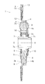
- FIG. 1 is a cross-sectional view of a clutch disk assembly according to an embodiment of the present invention.
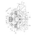
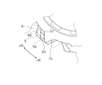
- the front view of a clutch disk assembly. The perspective view of a flange.
- the expanded partial view of FIG. 2 which shows the connection part of an output hub and a flange.
- the figure which expands and shows a pre-damper unit. The figure which expands and shows the stopper mechanism part of a pre-damper unit.
- FIG. 1 shows a clutch disk assembly 1 as an embodiment of the present invention.
- the clutch disk assembly 1 is a device for transmitting and interrupting torque from an engine (not shown) arranged on the left side of FIG. 1 to a transmission (not shown) arranged on the right side of FIG. .
- OO is the rotational axis of the clutch disk assembly 1.
- the clutch disk assembly 1 includes a clutch disk 2, a clutch plate 3 and a retaining plate 4 (input side member), first and second flanges 5 and 6, an output hub (output side member) 7, and a plurality of them.
- the torsion spring 8, a hysteresis torque generating mechanism 9, and a pre-damper unit 10 are provided.
- the clutch disc 2 has an annular cushioning plate 12 and an annular friction facing 14.
- the cushioning plate 12 has a plurality of mounting portions arranged side by side in the circumferential direction.
- the friction facing 14 is fixed to both surfaces of the cushioning plate 12 by rivets 13. Further, the inner peripheral portion of the cushioning plate 12 is fixed to the outer peripheral portion of the clutch plate 3 by rivets (not shown).
- An engine-side flywheel (not shown) is disposed on the left side of the friction facing 14 in FIG. 1, and the friction-facing 14 is pressed against the flywheel, whereby the engine-side torque is applied to the clutch disc assembly 1. Is entered.
- the clutch plate 3 and the retaining plate 4 are each formed in a disk shape, and are disposed opposite to each other in the axial direction with the first and second flanges 5 and 6 interposed therebetween. These two plates 3 and 4 are fixed by a stud pin 16 so as not to be relatively rotatable.
- the clutch plate 3 and the retaining plate 4 include four first storage portions 3 a and 4 a for storing the torsion springs 8 and four second storage portions in portions facing each other. 3b and 4b are formed.
- the four first storage portions 3a and 4a are arranged at intervals of 90 °, and the second storage portions 3b and 4b are arranged between them.
- Each of the storage portions 3a, 3b, 4a, 4b is formed so as to bulge outward in the axial direction (the clutch plate 3 is on the engine side and the retaining plate 4 is on the transmission side), and an opening is formed in the center portion. Yes.
- first and second flanges 5, 6 The first and second flanges 5 and 6 are disposed so as to be sandwiched between the clutch plate 3 and the retaining plate 4. Both the flanges 5 and 6 have the same shape, and the first flange 5 will be specifically described here.
- the first flange 5 is a disk-like plate, and has four first openings 5a and four second openings 5b arranged in the circumferential direction.
- the first opening 5a is larger than the second opening 5b in the radial direction and the rotation direction.
- the first opening 5 a is formed at a position corresponding to the first storage portions 3 a and 4 a of the clutch plate 3 and the retaining plate 4.
- the second opening 5 b is formed at a position corresponding to the second storage portions 3 b and 4 b of the clutch plate 3 and the retaining plate 4.
- the stud pin 16 has penetrated the inner peripheral part of 1st opening 5a, 6a of both the flanges 5 and 6 to an axial direction (refer FIG. 2).
- a spring support part (protrusion part) 5c is formed on one end face in the rotational direction of the four first openings 5a.
- the spring support 5c has a substantially rectangular shape.
- the end surfaces of the first coil spring 8a and the second coil spring 8b among the plurality of torsion springs 8 are in contact with the spring support portion 5c.
- the surface of the spring support portion 5c opposite to the surface that receives the torsion spring 8 is in contact with one end surface of the clutch plate 3 and the retaining plate 4 in the rotational direction of the first storage portions 3a and 4a.
- the spring support portion 5c of the first flange 5 is located between one end surface of the torsion spring 8 and one end surface of the first storage portions 3a and 4a of the clutch plate 3 and the retaining plate 4. It is pinched. Therefore, when the clutch plate 3 and the retaining plate 4 rotate in the + R direction of FIGS. 2 to 4, the first flange 5 is prohibited from rotating relative to the clutch plate 3 and the retaining plate 4, and these It will rotate integrally with both plates 3 and 4. When the clutch plate 3 and the retaining plate 4 rotate in the ⁇ R direction, the first flange 5 is allowed to rotate relative to the clutch plate 3 and the retaining plate 4 within a predetermined angle range.
- FIG. 4 which is an enlarged partial view of FIGS. 3 and 2
- a plurality of cutouts 5 d that open toward the inner periphery are formed in the inner periphery of the first flange 5.
- the second flange 6 has the same shape as the first flange 5. And about this 2nd flange 6, the spring support part 6c is clamped between the other end surface of the torsion spring 8, and the other end surface of the 1st accommodating parts 3a and 4a of the clutch plate 3 and the retaining plate 4. FIG. ing. Therefore, when the clutch plate 3 and the retaining plate 4 rotate in the ⁇ R direction, the second flange 6 is prohibited from rotating relative to the clutch plate 3 and the retaining plate 4. Will rotate together. When the clutch plate 3 and the retaining plate 4 rotate in the + R direction, the second flange 5 is allowed to rotate relative to the clutch plate 3 and the retaining plate 4 within a predetermined angle range.
- a plurality of notches 6d that open toward the inner peripheral side are formed in the inner peripheral portion of the second flange 6.
- the notches 5d and 6d in the inner peripheral portions of the flanges 5 and 6 are assembled with their phases shifted in the rotational direction.
- the output hub 7 is a cylindrical member, and as shown in FIG. 1, a spline hole 7a is formed in the inner periphery.
- the input shaft of the transmission can be spline engaged with the spline hole 7a.
- a plurality of first teeth 7b are formed on the outer peripheral surface of the output hub 7, and a plurality of second teeth 7c are formed on the outer peripheral surface of the end portion on the transmission side. Is formed.
- Each of the plurality of first teeth 7b is inserted into the notches 5d and 6d of the flanges 5 and 6 through a predetermined gap.
- the first and second flanges 5 and 6 are arranged in a state where the phase is shifted in the rotation direction. Therefore, as shown in FIG. 4, in the neutral state where no torque is input, the first gap G1 is formed between the first tooth 7b of the output hub 7 and the end surface in the rotational direction of the notch 5d of the first flange 5. A second gap G2 wider than the first gap G1 is formed between the first teeth 7b and the end face in the rotational direction of the notch 6d of the second flange 6.
- the torsion spring 8 has first to third coil springs 8a, 8b and 8c.
- the first coil spring 8 a and the second coil spring 8 b are disposed in the first openings 5 a and 6 a of the first and second flanges 5 and 6, and are formed by the first storage portions 3 a and 4 a of the clutch plate 3 and the retaining plate 4. It is supported.
- the second coil spring 8b is disposed on the inner periphery of the first coil spring 8a.
- the third coil spring 8 c is disposed in the second openings 5 b and 6 b of the first and second flanges 5 and 6 and is supported by the second storage portions 3 b and 4 b of the clutch plate 3 and the retaining plate 4. .
- the hysteresis torque generating mechanism 9 is arranged between the clutch plate 3 and the first flange 5, between the first flange 5 and the second flange 6, and between the second flange 6 and the retaining plate 4. Yes. Although a detailed description of the mechanism 9 is omitted, the friction washer that is prohibited from rotating relative to the clutch plate 3 beyond a predetermined angle range, the friction plate that contacts the side surface of the first flange 5, and the friction plate are connected to the first flange. It is comprised from the cone spring which presses to the 5 side.
- Pre-damper unit 10 As shown in FIGS. 1 and 5, the pre-damper unit 10 is disposed on the inner peripheral portion of the retaining plate 4 and on the outer peripheral portion on the transmission side of the output hub 7. Torque is input to the pre-damper unit 10 via the retaining plate 4.
- the pre-damper unit 10 includes a first sub-plate (intermediate plate) 21, a second sub-plate (output-side plate) 22, a plurality of outer peripheral pre-torsion springs 23, and a plurality of inner peripheral pre-torsion springs 24 ,have.
- FIG. 5 is an enlarged partial view of FIG.
- a plurality of notches 4c for housing springs are formed on the side surface of the retaining plate 4 on the transmission side.
- the outer periphery side pre-torsion spring 23 is accommodated in the plurality of notches 4c, and the end surface of the outer periphery side pre-torsion spring 23 is engaged with the end surface of the notch 4c.
- a part of the notch 4c on the engine side is open.
- the first sub-plate 21 is formed in a disc shape, and includes a plurality of first storage portions 21a formed on the outer peripheral portion and a plurality of second storage portions 21b formed on the inner peripheral portion. ing.
- the first sub-plate 21 is rotatable relative to the retaining plate 4 and the second sub-plate 22 within a predetermined angle range.
- the first storage portion 21 a is formed so as to swell toward the transmission side, and stores and holds the outer peripheral side pre-torsion spring 23 together with the notch 4 c of the retaining plate 4. Further, the end face of the outer peripheral pre-torsion spring 23 is engaged with the end face in the rotation direction of the first storage portion 21a.
- the second storage portion 21b is formed so as to swell toward the engine side, and stores and holds a part of the inner peripheral side pre-torsion spring 24. Further, the end face of the inner peripheral side pre-torsion spring 24 is engaged with the end face in the rotation direction of the second storage portion 21b.
- the second sub plate 22 is disposed on the transmission side of the first sub plate 21 so as to face the first sub plate 21.
- the second sub plate 22 is formed with a plurality of storage portions 22b that swell toward the transmission side, and stores and holds the inner peripheral side pre-torsion spring 24 together with the second storage portion 21b of the first sub plate 21.
- a plurality of teeth 22 c are formed on the inner peripheral portion of the second sub-plate 22, and the teeth 22 c mesh with the second teeth 7 c of the output hub 7.
- the outer peripheral side pre-torsion spring 23 and the inner peripheral side pre-torsion spring 24 act in series.
- the outer peripheral side pre-torsion spring 23 has higher rigidity than the inner peripheral side pre-torsion spring 24.
- an arc-shaped hole 21c having a predetermined length in the rotation direction is formed in the radial intermediate portion of the first sub-plate 21.
- an engagement protrusion 22d formed by bending toward the engine side is formed on a part of the outer peripheral portion of the second sub-plate 22, and the engagement protrusion 22d is formed through the first sub-plate via a predetermined gap. 21 is inserted into the arcuate hole 21c.
- a snap ring 26 is provided on the transmission side in the inner periphery of the second sub-plate 22.
- the snap ring 26 prevents the pre-damper unit 10 from coming out to the transmission side.
- the torsional spring 8 and the hysteresis torque generating mechanism 9 do not absorb the torsional vibration. And transmitted to the pre-damper unit 10.
- the outer peripheral side pre-torsion spring 23 and the inner peripheral side pre-torsion spring 24 operate in series, and the relative relationship between the retaining plate 4 and the first and second sub-plates 21 and 22 is relative. Rotation occurs.
- a small hysteresis torque generated by sliding of each member is generated (more specifically, a hysteresis torque generating mechanism is provided on the outer peripheral side of the output hub 7 of the main damper unit), and a screw having a small displacement angle. Vibration is attenuated.
- the pre-damper unit 10 can have a torsional characteristic with a wide angle and two stages.
- the operation of the pre-damper unit 10 as described above causes the output hub 7 and the first flange 5 to relatively rotate by a torsion angle corresponding to the gap G1 shown in FIG.
- the output hub 7 and the first flange 5 rotate integrally.
- the torsion spring 8 is elastically deformed, and the plates 3, 4 and the second flange 6, the first flange 5 and the output hub 7 are relatively rotated by an angle corresponding to the gap G2.
- the first teeth 7b of the output hub 7 come into contact with the + R direction end surface of the notch 6d of the second flange 6, and their relative rotation is prohibited. That is, the end surface of the notch 6d of the second flange 6 functions as a stopper.
- the clutch plate 3 and the retaining plate 4 rotate in the + R direction, on the contrary, the first flange 5 is prohibited from rotating relative to the clutch plate 3 and the retaining plate 4, and the second flange 6. Can be rotated relative to each other. Accordingly, when the pre-damper unit 10 operates and the first teeth 7b of the output hub 7 abut on the end surface in the ⁇ R direction of the notch 6d of the second flange 6, the output hub 7 and the second flange 6 are integrated. Rotate to. Thereafter, the torsion spring 8 is elastically deformed, and the plates 3, 4 and the first flange 5, the second flange 6 and the output hub 7 are relatively rotated by an angle corresponding to the gap G2.
- the first teeth 7b of the output hub 7 come into contact with the + R direction end surface of the notch 5d of the fifth flange 5, and their relative rotation is prohibited. That is, the end surface of the notch 5d of the first flange 5 functions as a stopper.
- the pre-damper unit 10 includes an outer peripheral side pre-torsion spring 23 and an inner peripheral side pre-torsion spring 24 that operate in series. For this reason, the wide angle in the pre-damper unit 10 can be realized.
- a part of the retaining plate 4 is made to function as an input side plate of the pre-damper unit 10. This eliminates the need for an input-side plate as compared with the conventional pre-damper unit, and the axial dimension can be shortened as compared with the conventional device.
- the rotation angle range of the second sub-plate 22 is regulated by the first sub-plate 21. For this reason, the pre-damper unit 10 can realize two-stage torsional characteristics.
- a stopper mechanism is realized by the output hub 7 and the two flanges 5 and 6. For this reason, it is not necessary to provide a stopper mechanism including a stop pin on the outer periphery of the flange as in the conventional device. Therefore, a wide space for the torsion spring can be secured, and high torque and wide angle can be easily realized.
- the configuration for prohibition can function as a spring seat.
- the wide angle of the pre-damper unit can be realized and the axial dimension can be shortened to improve the vehicle mountability. Further, the damper disk assembly of the present invention can realize multistage characteristics of the pre-damper unit.
Landscapes
- Engineering & Computer Science (AREA)
- General Engineering & Computer Science (AREA)
- Mechanical Engineering (AREA)
- Physics & Mathematics (AREA)
- Acoustics & Sound (AREA)
- Aviation & Aerospace Engineering (AREA)
- Mechanical Operated Clutches (AREA)
Abstract
プリダンパーユニットの広角化及び軸方向寸法の短縮化を実現する。このダンパーディスク組立体は、メインダンパーユニットと、プリダンパーユニットと、を備えている。プリダンパーユニットは、複数の外周側トーションスプリング(23)と、第2サブプレート(22)と、複数の内周側トーションスプリング(24)と、第1サブプレート(23)と、を有している。複数の外周側トーションスプリング(23)は、メインダンパーユニットのリティニングプレート(4)に係合し、トルクが入力される。第2サブプレート(22)は出力ハブ(7)に連結されている。複数の内周側トーションスプリング(24)は、第2サブプレート(22)に係合してトルクを伝達する。第1サブプレート(21)は、外周側トーションスプリング(23)と内周側トーションスプリング(24)とを直列的に作動させる。
Description
本発明は、ダンパーディスク組立体、特に、エンジンからの動力をトランスミッションの入力軸に伝達するためのダンパーディスク組立体に関する。
クラッチディスク組立体等に用いられるダンパーディスク組立体は、1対の入力プレートと、1対の入力プレートの軸方向間に配置されたハブフランジと、1対の入力プレートとハブフランジとを円周方向に弾性的に連結する複数のトーションスプリングと、を備えている。
また、特許文献1には、メインのダンパーユニットとは別に、トルクの小さい範囲での捩り振動を減衰するためのプリダンパーユニットを備えたクラッチディスク組立体が示されている。このプリダンパーユニットは、メインダンパーユニットからトルクが入力される1対の入力側プレートと、これらのプレートの間に挟まれるように配置された出力側プレートと、を有している。1対の入力側プレートは互いにリベットで一体回転するように固定されている。そして、1対の入力側プレートと出力側プレートとは、トーションスプリングによって弾性的に連結されている。
特許文献1に示されたクラッチディスク組立体では、メインダンパーユニットとは別にプリダンパーが設けられている。
しかし、従来のプリダンパーユニットでは、捩り角度の範囲は狭く、また捩り特性も1段である。このため、特にアイドリング時の捩り振動を効果的に抑えることができない。また、従来のプリダンパーユニットでは、プリダンパーユニットのためのスペースが大きく、特に軸方向寸法を短縮化する際の妨げになる。このため、車両への搭載時に他部材との干渉の可能性が高くなり、搭載性が低下するという問題がある。
本発明の課題は、プリダンパーユニットの広角化を実現するとともに、軸方向寸法の短縮化を実現して車両搭載性を向上させることにある。
本発明の別の課題は、プリダンパーユニットの多段特性化を可能にすることにある。
本発明の一側面に係るダンパーディスク組立体は、エンジンからのトルクをトランスミッションの入力軸に伝達するためのものであって、メインダンパーユニットと、プリダンパーユニットと、を備えている。メインダンパーユニットは、エンジンからのトルクが入力される入力側部材と、トランスミッションの入力軸に連結される出力側部材と、を有し、エンジンからの捩り振動を減衰して入力側部材に入力されるトルクを出力側部材に伝達する。プリダンパーユニットは、メインダンパーユニットからトルクが入力され、メインダンパーユニットに比較してトルクの小さい範囲での捩り振動を減衰して出力側部材にトルクを出力する。このプリダンパーユニットは、複数の外周側弾性部材と、出力側プレートと、複数の内周側弾性部材と、中間プレートと、を有している。複数の外周側弾性部材は、メインダンパーユニットの入力側部材に係合し、入力側部材からトルクが入力される。出力側プレートはメインダンパーユニットの出力側部材に連結されている。複数の内周側弾性部材は、複数の外周側弾性部材の内周側に配置され、出力側プレートに係合して出力側サブプレートにトルクを伝達する。中間プレートは、メインダンパーユニットの入力側部材及び出力側プレートと相対回転自在に配置され、複数の外周側弾性部材と複数の内周側弾性部材とを直列的に作動させる。
ここでは、プリダンパーユニットが、直列的に作動する外周側弾性部材と内周側弾性部材とを有している。このため、弾性部材の作動角度が増大し、プリダンパーユニット部分の広角化を実現できる。また、プリダンパーユニットの複数の外周側弾性部材がメインダンパーユニットの出力側プレートに係合しているので、従来のプリダンパーユニットに比較して入力側のプレートが不要になり、軸方向寸法を従来装置に比較して短縮できる。このため車両への搭載性が向上する。
本発明の別の側面に係るダンパーディスク組立体では、中間プレートは、複数の外周側弾性部材を収納する外周側収納部と、複数の内周側弾性部材を収納する内周側第1収納部と、を有する。
中間プレートによって外周側弾性部材と内周側弾性部材とが直列的に作動することになり、またこの中間プレートに形成された収納部によって外周側弾性部材及び内周側弾性部材が支持される。
本発明のさらに別の側面に係るダンパーディスク組立体では、出力側プレートは、円板状に形成されており、内周部に形成され出力側部材の外周部に係合する係合部と、中間プレートの内周側第1収納部とともに複数の内周側弾性部材を収納する内周側第2収納部と、を有している。
本発明のさらに別の側面に係るダンパーディスク組立体では、出力側プレートは、中間プレートに対する相対回転が所定の角度範囲内に規制されている。
ここでは、中間プレートに対する出力側プレートの相対回転が所定の角度範囲内に規制されているので、プリダンパーユニットの多段化を実現することができる。
本発明のさらに別の側面に係るダンパーディスク組立体では、中間部材は回転方向に所定の長さを有する円弧状の孔を有し、出力側プレートは円弧状の孔に所定の隙間を介して挿入された突起を有している。
以上のように本発明では、プリダンパーユニットの広角化を実現するとともに、軸方向寸法の短縮化を図って車両搭載性を向上できる。また、本発明では、プリダンパーユニットの多段特性化を実現できる。
本発明の一実施例としてのクラッチディスク組立体1を図1に示す。このクラッチディスク組立体1は、図1の左側に配置されたエンジン(図示せず)からのトルクを図1の右側に配置されたトランスミッション(図示せず)に伝達及び遮断するための装置である。図1においてO-Oがクラッチディスク組立体1の回転軸線である。
[全体構成]
このクラッチディスク組立体1は、クラッチディスク2と、クラッチプレート3及びリティニングプレート4(入力側部材)と、第1及び第2フランジ5,6と、出力ハブ(出力側部材)7と、複数のトーションスプリング8と、ヒステリシストルク発生機構9と、プリダンパーユニット10と、を備えている。
このクラッチディスク組立体1は、クラッチディスク2と、クラッチプレート3及びリティニングプレート4(入力側部材)と、第1及び第2フランジ5,6と、出力ハブ(出力側部材)7と、複数のトーションスプリング8と、ヒステリシストルク発生機構9と、プリダンパーユニット10と、を備えている。
[クラッチディスク2]
クラッチディスク2は、図1及び図2に示すように、環状のクッショニングプレート12と、環状の摩擦フェーシング14と、を有している。クッショニングプレート12は円周方向に並べて配置された複数の取付部を有する。摩擦フェーシング14はクッショニングプレート12の両面にリベット13によって固定されている。また、クッショニングプレート12の内周部はリベット(図示せず)によってクラッチプレート3の外周部に固定されている。なお、摩擦フェーシング14の図1左側にはエンジン側のフライホイール(図示せず)が配置されており、摩擦フェーシング14がフライホイールに押圧されることによって、クラッチディスク組立体1にエンジン側のトルクが入力される。
クラッチディスク2は、図1及び図2に示すように、環状のクッショニングプレート12と、環状の摩擦フェーシング14と、を有している。クッショニングプレート12は円周方向に並べて配置された複数の取付部を有する。摩擦フェーシング14はクッショニングプレート12の両面にリベット13によって固定されている。また、クッショニングプレート12の内周部はリベット(図示せず)によってクラッチプレート3の外周部に固定されている。なお、摩擦フェーシング14の図1左側にはエンジン側のフライホイール(図示せず)が配置されており、摩擦フェーシング14がフライホイールに押圧されることによって、クラッチディスク組立体1にエンジン側のトルクが入力される。
[クラッチプレート3及びリティニングプレート4]
クラッチプレート3及びリティニングプレート4は、それぞれ円板状に形成され、第1及び第2フランジ5,6を挟んで軸方向に対向して配置されている。そして、これらの両プレート3,4は、スタッドピン16によって相対回転不能に固定されている。
クラッチプレート3及びリティニングプレート4は、それぞれ円板状に形成され、第1及び第2フランジ5,6を挟んで軸方向に対向して配置されている。そして、これらの両プレート3,4は、スタッドピン16によって相対回転不能に固定されている。
クラッチプレート3及びリティニングプレート4には、図1及び図2に示すように、互いに対向する部分に、トーションスプリング8を収納する4つの第1収納部3a,4aと、4つの第2収納部3b,4bが形成されている。4つの第1収納部3a,4aは90°間隔で配置されており、第2収納部3b,4bはそれらの間に配置されている。また、各収納部3a,3b,4a,4bは、軸方向外側(クラッチプレート3はエンジン側、リティニングプレート4はトランスミッション側)に膨らむように形成されており、中央部に開口が形成されている。
[第1及び第2フランジ5,6]
第1及び第2フランジ5,6はクラッチプレート3とリティニングプレート4との間に挟まれるように配置されている。両フランジ5,6は同じ形状であり、ここでは、第1フランジ5について具体的に説明する。
第1及び第2フランジ5,6はクラッチプレート3とリティニングプレート4との間に挟まれるように配置されている。両フランジ5,6は同じ形状であり、ここでは、第1フランジ5について具体的に説明する。
図3に示すように、第1フランジ5は、円板状のプレートであり、円周方向に並ぶ4つの第1開口5aと4つの第2開口5bとを有している。第1開口5aは第2開口5bより径方向及び回転方向に関して大きく形成されている。第1開口5aはクラッチプレート3及びリティニングプレート4の第1収納部3a,4aに対応する位置に形成されている。また、第2開口5bはクラッチプレート3及びリティニングプレート4の第2収納部3b,4bに対応する位置に形成されている。
なお、スタッドピン16は、両フランジ5,6の第1開口5a,6aの内周部を軸方向に貫通している(図2参照)。
4つの第1開口5aの回転方向の一方の端面には、軸方向両側に突出するスプリング支持部(突起部)5cが形成されている。スプリング支持部5cはほぼ矩形形状である。そして、複数のトーションスプリング8のうちの第1コイルスプリング8a及び第2コイルスプリング8bの端面が、スプリング支持部5cに当接している。また、スプリング支持部5cのトーションスプリング8を受ける面と逆側の面は、クラッチプレート3及びリティニングプレート4の第1収納部3a,4aの回転方向の一方の端面に当接している。
以上のような構成により、第1フランジ5のスプリング支持部5cは、トーションスプリング8の一方の端面とクラッチプレート3及びリティニングプレート4の第1収納部3a,4aの一方の端面との間に挟持されている。したがって、クラッチプレート3及びリティニングプレート4が図2~図4の+R方向に回転する際には、第1フランジ5は、クラッチプレート3及びリティニングプレート4との相対回転が禁止され、これらの両プレート3,4と一体回転することになる。なお、クラッチプレート3及びリティニングプレート4が-R方向に回転する際には、第1フランジ5は、クラッチプレート3及びリティニングプレート4と所定の角度範囲で相対回転が許容される。
また、第1フランジ5の内周部には、図3及び図2の拡大部分図である図4に示すように、内周側に向かって開く複数の切欠き5dが形成されている。
前述のように、第2フランジ6は第1フランジ5と同一形状である。そして、この第2フランジ6については、スプリング支持部6cは、トーションスプリング8の他方の端面とクラッチプレート3及びリティニングプレート4の第1収納部3a,4aの他方の端面との間に挟持されている。したがって、クラッチプレート3及びリティニングプレート4が-R方向に回転する際には、第2フランジ6は、クラッチプレート3及びリティニングプレート4との相対回転が禁止され、これらの両プレート3,4と一体回転することになる。なお、クラッチプレート3及びリティニングプレート4が+R方向に回転する際には、第2フランジ5は、クラッチプレート3及びリティニングプレート4と所定の角度範囲で相対回転が許容される。
また、第2フランジ6の内周部には内周側に向かって開く複数の切欠き6dが形成されている。
なお、図2及び図4に示すように、両フランジ5,6の内周部の切欠き5d,6dは回転方向において位相がずれた状態で組み付けられている。
[出力ハブ7]
出力ハブ7は、円筒状の部材であり、図1に示すように、内周部にスプライン孔7aが形成されている。このスプライン孔7aにトランスミッションの入力軸がスプライン係合可能である。
出力ハブ7は、円筒状の部材であり、図1に示すように、内周部にスプライン孔7aが形成されている。このスプライン孔7aにトランスミッションの入力軸がスプライン係合可能である。
また出力ハブ7の外周面には、図1、図2及び図4に示すように、複数の第1歯7bが形成され、さらにトランスミッション側の端部外周面には複数の第2歯7cが形成されている。複数の第1歯7bのそれぞれは、所定の隙間を介して両フランジ5,6の切欠き5d,6dの内部に挿入されている。
具体的には、前述のように、第1及び第2フランジ5,6は回転方向に位相がずれた状態で配置されている。したがって、図4に示すように、トルクが入力されていない中立状態では、出力ハブ7の第1歯7bと第1フランジ5の切欠き5dの回転方向の端面との間には第1隙間G1が形成され、第1歯7bと第2フランジ6の切欠き6dの回転方向の端面との間には第1隙間G1より広い第2隙間G2が形成されている。
[トーションスプリング8]
トーションスプリング8は、第1~第3コイルスプリング8a,8b,8cを有している。第1コイルスプリング8a及び第2コイルスプリング8bは、第1及び第2フランジ5,6の第1開口5a,6aに配置され、クラッチプレート3及びリティニングプレート4の第1収納部3a,4aによって支持されている。第2コイルスプリング8bは第1コイルスプリング8aの内周部に配置されている。また、第3コイルスプリング8cは、第1及び第2フランジ5,6の第2開口5b,6bに配置され、クラッチプレート3及びリティニングプレート4の第2収納部3b,4bによって支持されている。
トーションスプリング8は、第1~第3コイルスプリング8a,8b,8cを有している。第1コイルスプリング8a及び第2コイルスプリング8bは、第1及び第2フランジ5,6の第1開口5a,6aに配置され、クラッチプレート3及びリティニングプレート4の第1収納部3a,4aによって支持されている。第2コイルスプリング8bは第1コイルスプリング8aの内周部に配置されている。また、第3コイルスプリング8cは、第1及び第2フランジ5,6の第2開口5b,6bに配置され、クラッチプレート3及びリティニングプレート4の第2収納部3b,4bによって支持されている。
[ヒステリシストルク発生機構9]
ヒステリシストルク発生機構9は、クラッチプレート3と第1フランジ5の間、第1フランジ5と第2フランジ6との間、第2フランジ6とリティニングプレート4の間の内周部に配置されている。この機構9の詳細説明は省略するが、クラッチプレート3との所定の角度範囲を超える相対回転が禁止されたフリクションワッシャ、第1フランジ5の側面に当接するフリクションプレート、及びフリクションプレートを第1フランジ5の側面に押圧するコーンスプリングから構成されている。
ヒステリシストルク発生機構9は、クラッチプレート3と第1フランジ5の間、第1フランジ5と第2フランジ6との間、第2フランジ6とリティニングプレート4の間の内周部に配置されている。この機構9の詳細説明は省略するが、クラッチプレート3との所定の角度範囲を超える相対回転が禁止されたフリクションワッシャ、第1フランジ5の側面に当接するフリクションプレート、及びフリクションプレートを第1フランジ5の側面に押圧するコーンスプリングから構成されている。
[プリダンパーユニット10]
プリダンパーユニット10は、図1及び図5に示すように、リティニングプレート4の内周部で、かつ出力ハブ7のトランスミッション側の外周部に配置されている。プリダンパーユニット10には、リティニングプレート4を介してトルクが入力される。このプリダンパーユニット10は、第1サブプレート(中間プレート)21と、第2サブプレート(出力側プレート)22と、複数の外周側プリトーションスプリング23と、複数の内周側プリトーションスプリング24と、を有している。なお、図5は図1の拡大部分図である。
プリダンパーユニット10は、図1及び図5に示すように、リティニングプレート4の内周部で、かつ出力ハブ7のトランスミッション側の外周部に配置されている。プリダンパーユニット10には、リティニングプレート4を介してトルクが入力される。このプリダンパーユニット10は、第1サブプレート(中間プレート)21と、第2サブプレート(出力側プレート)22と、複数の外周側プリトーションスプリング23と、複数の内周側プリトーションスプリング24と、を有している。なお、図5は図1の拡大部分図である。
図5に示すように、リティニングプレート4のトランスミッション側の側面には、スプリング収納用の複数の切欠き4cが形成されている。この複数の切欠き4cに外周側プリトーションスプリング23が収納されるとともに、外周側プリトーションスプリング23の端面が切欠き4cの端面に係合している。なお、切欠き4cのエンジン側の一部は開口している。
第1サブプレート21は、円板状に形成されており、外周部に形成された複数の第1収納部21aと、内周部に形成された複数の第2収納部21bと、を有している。この第1サブプレート21は、リティニングプレート4に対しても、また第2サブプレート22に対しても、所定の角度範囲で相対回転自在である。
第1収納部21aは、トランスミッション側に膨らむように形成されており、リティニングプレート4の切欠き4cとともに外周側プリトーションスプリング23を収納し、保持している。また、第1収納部21aの回転方向の端面には外周側プリトーションスプリング23の端面が係合している。
第2収納部21bは、エンジン側に膨らむように形成されており、内周側プリトーションスプリング24の一部を収納し、保持している。また、第2収納部21bの回転方向端面には内周側プリトーションスプリング24の端面が係合している。
第2サブプレート22は、第1サブプレート21のトランスミッション側に第1サブプレート21と対向するように配置されている。第2サブプレート22には、トランスミッション側に膨らむ複数の収納部22bが形成されており、第1サブプレート21の第2収納部21bとともに内周側プリトーションスプリング24を収納し、保持している。また、第2サブプレート22の内周部には複数の歯22cが形成されており、この歯22cが出力ハブ7の第2歯7cと噛み合っている。
このような構成では、外周側プリトーションスプリング23と内周側プリトーションスプリング24とは直列的に作用する。なお、この例では、外周側プリトーションスプリング23は内周側プリトーションスプリング24より高い剛性を有している。
また、第1サブプレート21の径方向中間部には、回転方向に所定の長さを有する円弧状の孔21cが形成されている。一方、第2サブプレート22の外周部の一部には、エンジン側に折り曲げて形成された係合突起22dが形成されており、この係合突起22dが所定の隙間を介して第1サブプレート21の円弧状の孔21cに挿入されている。
なお、第2サブプレート22の内周部において、トランスミッション側にはスナップリング26が設けられている。このスナップリング26により、プリダンパーユニット10のトランスミッション側への抜け出しが防止されている。
[動作]
摩擦フェーシング14がエンジン側のフライホイールに押圧されると、エンジンからのトルクはクラッチディスク2を介してクラッチプレート3及びリティニングプレート4に伝達される。このトルクは、トーションスプリング8→第1フランジ5又は第2フランジ6→出力ハブ7の経路で伝達される。また、リティニングプレート4に伝達されたトルクは、リティニングプレート4→プリダンパーユニット10→出力ハブ7の経路でトランスミッション側のシャフトに出力される。
摩擦フェーシング14がエンジン側のフライホイールに押圧されると、エンジンからのトルクはクラッチディスク2を介してクラッチプレート3及びリティニングプレート4に伝達される。このトルクは、トーションスプリング8→第1フランジ5又は第2フランジ6→出力ハブ7の経路で伝達される。また、リティニングプレート4に伝達されたトルクは、リティニングプレート4→プリダンパーユニット10→出力ハブ7の経路でトランスミッション側のシャフトに出力される。
具体的には、アイドリング時等において、エンジン側からクラッチディスク組立体1に変位角の小さな捩じり振動が伝達されると、この捩り振動はトーションスプリング8及びヒステリシストルク発生機構9では吸収されず、プリダンパーユニット10に伝達される。そして、プリダンパーユニット10では、外周側プリトーションスプリング23と内周側プリトーションスプリング24とが直列的に作動し、リティニングプレート4と第1及び第2サブプレート21,22との間で相対回転が生じる。ここでは、各部材の摺動によって生じる小さいヒステリシストルクが発生され(より詳細には、メインダンパーユニットの出力ハブ7の外周側にヒステリシストルク発生機構が設けられている)、変位角の小さな捩じり振動が減衰される。
ここで、捩り振動が小さい場合は、内周側プリトーションスプリング24のみ、または内周側プリトーションスプリング24及び外周側プリトーションスプリング23が伸縮する。そして、捩り振動がさらに大きくなって内周側プリトーションスプリング24の弾性変形が大きくなると、第2サブプレート22の係合突起22dが第1サブプレート21の円弧状の孔21cの端面に当接する。したがって、これ以降は、外周側プリトーションスプリング23のみがさらに弾性変形することになる。
以上のような動作によって、プリダンパーユニット10において、捩り特性の広角化及2段化が可能になる。
次に、さらに大きな変位角を有する捩じり振動がクラッチディスク組立体1に伝達された場合について以下に説明する。
このような状況において、クラッチプレート3及びリティニングプレート4が-R方向に回転する場合は、第1フランジ5はこれらの両プレート3,4と相対回転が可能であるが、第2フランジ6は両プレート3,4と相対回転が禁止されて一体的に回転する。したがって、両プレート3,4が-R方向に回転すると、トルクは両プレート3,4からプリダンパーユニット10に伝達されるとともに、トーションスプリング8を介して第1フランジ5に伝達され、さらに出力ハブ7に伝達される。
このとき、前述のようなプリダンパーユニット10の作動によって出力ハブ7と第1フランジ5とが、図4に示した隙間G1に相当する捩じり角度だけ相対回転する。そして、出力ハブ7の第1歯7bが第1フランジ5の切欠き5dの+R方向の端面に当接すると、出力ハブ7と第1フランジ5とは一体的に回転する。その後、トーションスプリング8が弾性変形して、両プレート3,4及び第2フランジ6と、第1フランジ5及び出力ハブ7と、が隙間G2に相当する角度だけ相対回転する。すると、出力ハブ7の第1歯7bが第2フランジ6の切欠き6dの+R方向の端面に当接し、これらの相対回転が禁止される。すなわち、第2フランジ6の切欠き6dの端面がストッパとして機能する。
また、クラッチプレート3及びリティニングプレート4が+R方向に回転する場合は、以上とは逆に、第1フランジ5がクラッチプレート3及びリティニングプレート4との相対回転が禁止され、第2フランジ6が相対回転可能になる。したがって、プリダンパーユニット10が作動して出力ハブ7の第1歯7bが第2フランジ6の切欠き6dの-R方向の端面に当接すると、出力ハブ7と第2フランジ6とは一体的に回転する。その後、トーションスプリング8が弾性変形して、両プレート3,4及び第1フランジ5と、第2フランジ6及び出力ハブ7と、が隙間G2に相当する角度だけ相対回転する。すると、出力ハブ7の第1歯7bが第5フランジ5の切欠き5dの+R方向の端面に当接し、これらの相対回転が禁止される。すなわち、第1フランジ5の切欠き5dの端面がストッパとして機能する。
[特徴]
(1)プリダンパーユニット10が、直列的に作動する外周側プリトーションスプリング23及び内周側プリトーションスプリング24を有している。このため、プリダンパーユニット10における広角化を実現できる。
(1)プリダンパーユニット10が、直列的に作動する外周側プリトーションスプリング23及び内周側プリトーションスプリング24を有している。このため、プリダンパーユニット10における広角化を実現できる。
(2)リティニングプレート4の一部をプリダンパーユニット10の入力側プレートとして機能させている。このため、従来のプリダンパーユニットに比較して入力側のプレートが不要になり、軸方向寸法を従来装置に比較して短縮できる。
(3)外周側プリトーションスプリング23と内周側プリトーションスプリング24とを連結する第1サブプレート21によって、外周側及び内周側トーションスプリング23,24の支持を行っている。このため、少ない部品点数で広角化を実現できる。
(4)第1サブプレート21によって第2サブプレート22の回転角度範囲を規制している。このため、プリダンパーユニット10において捩り特性の2段化を実現できる。
(5)出力ハブ7と2つのフランジ5,6とによってストッパ機構を実現している。このため、従来装置のようにフランジ外周部にストップピンを含むストッパ機構を設ける必要がない。したがって、トーションスプリングのためのスペースを広く確保でき、高トルク化、及び広角化を容易に実現することができる。
(6)各フランジ5,6に形成されたスプリング支持部5c,6cによってトーションスプリング8の端面を支持しているので、各フランジ5,6を入力側のプレート3,4に対して相対回転を禁止するための構成を、スプリングシートとして機能させることができる。
(7)2つのフランジ5,6を同一形状としているので、製造コストを抑える事ができる。
[他の実施形態]
本発明は以上のような実施形態に限定されるものではなく、本発明の範囲を逸脱することなく種々の変形又は修正が可能である。
本発明は以上のような実施形態に限定されるものではなく、本発明の範囲を逸脱することなく種々の変形又は修正が可能である。
(a)第1サブプレート21と第2サブプレート22との相対回転角度範囲を規制するための構成は前記実施形態に限定されない。
(b)プリダンパーユニット10における外周側プリトーションスプリング23及び内周側プリトーションスプリング24の剛性については、前記実施形態は一例であって、前記実施形態に限定されない。
本発明のダンパーディスク組立体では、プリダンパーユニットの広角化を実現するとともに、軸方向寸法の短縮化を図って車両搭載性を向上できる。また、本発明のダンパーディスク組立体では、プリダンパーユニットの多段特性化を実現できる。
1 クラッチディスク組立体
2 クラッチディスク
3 クラッチプレート(入力側部材)
4 リティニングプレート(入力側部材)
7 出力ハブ(出力側部材)
8 トーションスプリング
10 プリダンパーユニット
21 第1サブプレート(中間プレート)
21c 円弧状の孔
22 第2サブプレート(出力側プレート)
22d 突起
23 外周側プリトーションスプリング
24 内周側プリトーションスプリング
2 クラッチディスク
3 クラッチプレート(入力側部材)
4 リティニングプレート(入力側部材)
7 出力ハブ(出力側部材)
8 トーションスプリング
10 プリダンパーユニット
21 第1サブプレート(中間プレート)
21c 円弧状の孔
22 第2サブプレート(出力側プレート)
22d 突起
23 外周側プリトーションスプリング
24 内周側プリトーションスプリング
Claims (5)
- エンジンからのトルクをトランスミッションの入力軸に伝達するためのダンパーディスク組立体であって、
前記エンジンからのトルクが入力される入力側部材と、前記トランスミッションの入力軸に連結される出力側部材と、を有し、エンジンからの捩り振動を減衰して前記入力側部材に入力されるトルクを前記出力側部材に伝達するメインダンパーユニットと、
前記メインダンパーユニットからトルクが入力され、前記メインダンパーユニットに比較してトルクの小さい範囲での捩り振動を減衰して前記出力側部材にトルクを出力するプリダンパーユニットと、
を備え、
前記プリダンパーユニットは、
前記メインダンパーユニットの入力側部材に係合し、前記入力側部材からトルクが入力される複数の外周側弾性部材と、
前記メインダンパーユニットの出力側部材に連結された出力側プレートと、
前記複数の外周側弾性部材の内周側に配置され、前記出力側プレートに係合して前記出力側サブプレートにトルクを伝達する複数の内周側弾性部材と、
前記メインダンパーユニットの入力側部材及び前記出力側プレートと相対回転自在に配置され、前記複数の外周側弾性部材と前記複数の内周側弾性部材とを直列的に作動させるための中間プレートと、
を有する、
ダンパーディスク組立体。 - 前記中間プレートは、
前記複数の外周側弾性部材を収納する外周側収納部と、
前記複数の内周側弾性部材を収納する内周側第1収納部と、
を有する、請求項1に記載のダンパーディスク組立体。 - 前記出力側プレートは、円板状に形成されており、
内周部に形成され前記出力側部材の外周部に係合する係合部と、
前記中間プレートの内周側第1収納部とともに前記複数の内周側弾性部材を収納する内周側第2収納部と、
を有している、請求項2に記載のダンパーディスク組立体。 - 前記出力側プレートは、前記中間プレートに対する相対回転が所定の角度範囲内に規制されている、請求項1から3のいずれかに記載のダンパーディスク組立体。
- 前記中間部材は回転方向に所定の長さを有する円弧状の孔を有し、
前記出力側プレートは前記円弧状の孔に所定の隙間を介して挿入された突起を有している、
請求項4に記載のダンパーディスク組立体。
Priority Applications (2)
| Application Number | Priority Date | Filing Date | Title |
|---|---|---|---|
| DE112016000680.2T DE112016000680T5 (de) | 2015-02-10 | 2016-02-05 | Dämpfungsscheibenanordnung |
| CN201680009269.3A CN107208709B (zh) | 2015-02-10 | 2016-02-05 | 减震片组件 |
Applications Claiming Priority (2)
| Application Number | Priority Date | Filing Date | Title |
|---|---|---|---|
| JP2015024329A JP6545972B2 (ja) | 2015-02-10 | 2015-02-10 | ダンパーディスク組立体 |
| JP2015-024329 | 2015-02-10 |
Publications (1)
| Publication Number | Publication Date |
|---|---|
| WO2016129520A1 true WO2016129520A1 (ja) | 2016-08-18 |
Family
ID=56614429
Family Applications (1)
| Application Number | Title | Priority Date | Filing Date |
|---|---|---|---|
| PCT/JP2016/053494 Ceased WO2016129520A1 (ja) | 2015-02-10 | 2016-02-05 | ダンパーディスク組立体 |
Country Status (4)
| Country | Link |
|---|---|
| JP (1) | JP6545972B2 (ja) |
| CN (1) | CN107208709B (ja) |
| DE (1) | DE112016000680T5 (ja) |
| WO (1) | WO2016129520A1 (ja) |
Families Citing this family (1)
| Publication number | Priority date | Publication date | Assignee | Title |
|---|---|---|---|---|
| CN108443349B (zh) * | 2018-04-04 | 2023-06-16 | 华南理工大学 | 一种变齿侧间隙的三级扭转减振结构的新型离合器从动盘 |
Citations (5)
| Publication number | Priority date | Publication date | Assignee | Title |
|---|---|---|---|---|
| JPS6084431A (ja) * | 1983-09-14 | 1985-05-13 | ヴァレオ | 2つの段階の振動止め装置を備えたクラツチ板 |
| JPS63289328A (ja) * | 1987-03-13 | 1988-11-25 | ルーク・ラメレン・ウント・クツプルングスバウ・ゲゼルシヤフト・ミツト・ベシユレンクテル・ハフツング | 車両のパワートレーン内に設けた構成部材 |
| JPH02146230U (ja) * | 1989-05-16 | 1990-12-12 | ||
| JPH11173380A (ja) * | 1997-12-12 | 1999-06-29 | Exedy Corp | ダンパーディスク組立体 |
| JPH11173382A (ja) * | 1997-12-12 | 1999-06-29 | Exedy Corp | ダンパーディスク組立体 |
Family Cites Families (6)
| Publication number | Priority date | Publication date | Assignee | Title |
|---|---|---|---|---|
| JP3805908B2 (ja) * | 1998-09-18 | 2006-08-09 | 株式会社エクセディ | ダンパーディスク組立体 |
| JP3732021B2 (ja) * | 1998-09-18 | 2006-01-05 | 株式会社エクセディ | ダンパー機構 |
| JP2003278791A (ja) * | 2002-03-27 | 2003-10-02 | Nissan Diesel Motor Co Ltd | クラッチディスク組立体 |
| JP4495936B2 (ja) * | 2003-09-25 | 2010-07-07 | 株式会社エクセディ | クラッチディスク組立体 |
| DE102008017561A1 (de) * | 2007-04-30 | 2008-11-06 | Luk Lamellen Und Kupplungsbau Beteiligungs Kg | Kupplungsscheibe |
| CN201382098Y (zh) * | 2009-02-03 | 2010-01-13 | 潍坊帅克机械有限责任公司 | 重载汽车整体弹性从动盘装置 |
-
2015
- 2015-02-10 JP JP2015024329A patent/JP6545972B2/ja active Active
-
2016
- 2016-02-05 WO PCT/JP2016/053494 patent/WO2016129520A1/ja not_active Ceased
- 2016-02-05 DE DE112016000680.2T patent/DE112016000680T5/de not_active Withdrawn
- 2016-02-05 CN CN201680009269.3A patent/CN107208709B/zh not_active Expired - Fee Related
Patent Citations (5)
| Publication number | Priority date | Publication date | Assignee | Title |
|---|---|---|---|---|
| JPS6084431A (ja) * | 1983-09-14 | 1985-05-13 | ヴァレオ | 2つの段階の振動止め装置を備えたクラツチ板 |
| JPS63289328A (ja) * | 1987-03-13 | 1988-11-25 | ルーク・ラメレン・ウント・クツプルングスバウ・ゲゼルシヤフト・ミツト・ベシユレンクテル・ハフツング | 車両のパワートレーン内に設けた構成部材 |
| JPH02146230U (ja) * | 1989-05-16 | 1990-12-12 | ||
| JPH11173380A (ja) * | 1997-12-12 | 1999-06-29 | Exedy Corp | ダンパーディスク組立体 |
| JPH11173382A (ja) * | 1997-12-12 | 1999-06-29 | Exedy Corp | ダンパーディスク組立体 |
Also Published As
| Publication number | Publication date |
|---|---|
| CN107208709A (zh) | 2017-09-26 |
| JP2016148359A (ja) | 2016-08-18 |
| CN107208709B (zh) | 2020-04-10 |
| JP6545972B2 (ja) | 2019-07-17 |
| DE112016000680T5 (de) | 2017-11-02 |
Similar Documents
| Publication | Publication Date | Title |
|---|---|---|
| JP6541983B2 (ja) | ダンパーディスク組立体 | |
| US10161459B2 (en) | Damper disc assembly | |
| JP5705935B2 (ja) | ダンパディスク組立体 | |
| KR20090077058A (ko) | 댐퍼 기구 | |
| WO2008041634A1 (fr) | Mécanisme d'amortisseur | |
| JP6965566B2 (ja) | トルク変動吸収装置 | |
| JP6541969B2 (ja) | 動力伝達装置及びトルクコンバータのロックアップ装置 | |
| JP7477396B2 (ja) | ダンパ装置 | |
| WO2016129182A1 (ja) | ダンパーディスク組立体 | |
| WO2016129183A1 (ja) | ダンパーディスク組立体 | |
| JP7473420B2 (ja) | ダンパ装置 | |
| JP4527134B2 (ja) | ダンパー機構 | |
| JP7473419B2 (ja) | ダンパ装置 | |
| CN114635948A (zh) | 减振装置 | |
| WO2016129520A1 (ja) | ダンパーディスク組立体 | |
| JP6782349B2 (ja) | ダンパーディスク組立体 | |
| JP7461827B2 (ja) | ダンパ装置 | |
| JP2013167309A (ja) | 捻り振動低減装置 | |
| JP2000027945A (ja) | ダンパー機構 | |
| JP2019090428A (ja) | ダンパディスク組立体 | |
| JP2023010399A (ja) | ダンパ装置 | |
| JP2021063570A (ja) | ダンパ装置 | |
| JP2021038762A (ja) | ダンパ装置 | |
| JP2019163853A (ja) | ダンパ装置 | |
| JP6976874B2 (ja) | 動力伝達構造及び動力伝達装置 |
Legal Events
| Date | Code | Title | Description |
|---|---|---|---|
| 121 | Ep: the epo has been informed by wipo that ep was designated in this application |
Ref document number: 16749164 Country of ref document: EP Kind code of ref document: A1 |
|
| WWE | Wipo information: entry into national phase |
Ref document number: 112016000680 Country of ref document: DE |
|
| 122 | Ep: pct application non-entry in european phase |
Ref document number: 16749164 Country of ref document: EP Kind code of ref document: A1 |