WO2016129391A1 - 接合構造体の製造方法および接合構造体 - Google Patents
接合構造体の製造方法および接合構造体 Download PDFInfo
- Publication number
- WO2016129391A1 WO2016129391A1 PCT/JP2016/052371 JP2016052371W WO2016129391A1 WO 2016129391 A1 WO2016129391 A1 WO 2016129391A1 JP 2016052371 W JP2016052371 W JP 2016052371W WO 2016129391 A1 WO2016129391 A1 WO 2016129391A1
- Authority
- WO
- WIPO (PCT)
- Prior art keywords
- stage
- perforated
- manufacturing
- laser
- joined
- Prior art date
- Legal status (The legal status is an assumption and is not a legal conclusion. Google has not performed a legal analysis and makes no representation as to the accuracy of the status listed.)
- Ceased
Links
Images


Classifications
-
- B—PERFORMING OPERATIONS; TRANSPORTING
- B29—WORKING OF PLASTICS; WORKING OF SUBSTANCES IN A PLASTIC STATE IN GENERAL
- B29C—SHAPING OR JOINING OF PLASTICS; SHAPING OF MATERIAL IN A PLASTIC STATE, NOT OTHERWISE PROVIDED FOR; AFTER-TREATMENT OF THE SHAPED PRODUCTS, e.g. REPAIRING
- B29C66/00—General aspects of processes or apparatus for joining preformed parts
- B29C66/01—General aspects dealing with the joint area or with the area to be joined
- B29C66/02—Preparation of the material, in the area to be joined, prior to joining or welding
- B29C66/024—Thermal pre-treatments
- B29C66/0246—Cutting or perforating, e.g. burning away by using a laser or using hot air
-
- B—PERFORMING OPERATIONS; TRANSPORTING
- B23—MACHINE TOOLS; METAL-WORKING NOT OTHERWISE PROVIDED FOR
- B23K—SOLDERING OR UNSOLDERING; WELDING; CLADDING OR PLATING BY SOLDERING OR WELDING; CUTTING BY APPLYING HEAT LOCALLY, e.g. FLAME CUTTING; WORKING BY LASER BEAM
- B23K26/00—Working by laser beam, e.g. welding, cutting or boring
- B23K26/20—Bonding
- B23K26/32—Bonding taking account of the properties of the material involved
- B23K26/324—Bonding taking account of the properties of the material involved involving non-metallic parts
-
- B—PERFORMING OPERATIONS; TRANSPORTING
- B23—MACHINE TOOLS; METAL-WORKING NOT OTHERWISE PROVIDED FOR
- B23K—SOLDERING OR UNSOLDERING; WELDING; CLADDING OR PLATING BY SOLDERING OR WELDING; CUTTING BY APPLYING HEAT LOCALLY, e.g. FLAME CUTTING; WORKING BY LASER BEAM
- B23K26/00—Working by laser beam, e.g. welding, cutting or boring
- B23K26/36—Removing material
- B23K26/38—Removing material by boring or cutting
- B23K26/382—Removing material by boring or cutting by boring
- B23K26/384—Removing material by boring or cutting by boring of specially shaped holes
-
- B—PERFORMING OPERATIONS; TRANSPORTING
- B23—MACHINE TOOLS; METAL-WORKING NOT OTHERWISE PROVIDED FOR
- B23K—SOLDERING OR UNSOLDERING; WELDING; CLADDING OR PLATING BY SOLDERING OR WELDING; CUTTING BY APPLYING HEAT LOCALLY, e.g. FLAME CUTTING; WORKING BY LASER BEAM
- B23K26/00—Working by laser beam, e.g. welding, cutting or boring
- B23K26/60—Preliminary treatment
-
- B—PERFORMING OPERATIONS; TRANSPORTING
- B29—WORKING OF PLASTICS; WORKING OF SUBSTANCES IN A PLASTIC STATE IN GENERAL
- B29C—SHAPING OR JOINING OF PLASTICS; SHAPING OF MATERIAL IN A PLASTIC STATE, NOT OTHERWISE PROVIDED FOR; AFTER-TREATMENT OF THE SHAPED PRODUCTS, e.g. REPAIRING
- B29C37/00—Component parts, details, accessories or auxiliary operations, not covered by group B29C33/00 or B29C35/00
- B29C37/0078—Measures or configurations for obtaining anchoring effects in the contact areas between layers
- B29C37/0082—Mechanical anchoring
-
- B—PERFORMING OPERATIONS; TRANSPORTING
- B29—WORKING OF PLASTICS; WORKING OF SUBSTANCES IN A PLASTIC STATE IN GENERAL
- B29C—SHAPING OR JOINING OF PLASTICS; SHAPING OF MATERIAL IN A PLASTIC STATE, NOT OTHERWISE PROVIDED FOR; AFTER-TREATMENT OF THE SHAPED PRODUCTS, e.g. REPAIRING
- B29C45/00—Injection moulding, i.e. forcing the required volume of moulding material through a nozzle into a closed mould; Apparatus therefor
- B29C45/14—Injection moulding, i.e. forcing the required volume of moulding material through a nozzle into a closed mould; Apparatus therefor incorporating preformed parts or layers, e.g. injection moulding around inserts or for coating articles
-
- B—PERFORMING OPERATIONS; TRANSPORTING
- B29—WORKING OF PLASTICS; WORKING OF SUBSTANCES IN A PLASTIC STATE IN GENERAL
- B29C—SHAPING OR JOINING OF PLASTICS; SHAPING OF MATERIAL IN A PLASTIC STATE, NOT OTHERWISE PROVIDED FOR; AFTER-TREATMENT OF THE SHAPED PRODUCTS, e.g. REPAIRING
- B29C45/00—Injection moulding, i.e. forcing the required volume of moulding material through a nozzle into a closed mould; Apparatus therefor
- B29C45/14—Injection moulding, i.e. forcing the required volume of moulding material through a nozzle into a closed mould; Apparatus therefor incorporating preformed parts or layers, e.g. injection moulding around inserts or for coating articles
- B29C45/14311—Injection moulding, i.e. forcing the required volume of moulding material through a nozzle into a closed mould; Apparatus therefor incorporating preformed parts or layers, e.g. injection moulding around inserts or for coating articles using means for bonding the coating to the articles
-
- B—PERFORMING OPERATIONS; TRANSPORTING
- B29—WORKING OF PLASTICS; WORKING OF SUBSTANCES IN A PLASTIC STATE IN GENERAL
- B29C—SHAPING OR JOINING OF PLASTICS; SHAPING OF MATERIAL IN A PLASTIC STATE, NOT OTHERWISE PROVIDED FOR; AFTER-TREATMENT OF THE SHAPED PRODUCTS, e.g. REPAIRING
- B29C65/00—Joining or sealing of preformed parts, e.g. welding of plastics materials; Apparatus therefor
- B29C65/02—Joining or sealing of preformed parts, e.g. welding of plastics materials; Apparatus therefor by heating, with or without pressure
- B29C65/14—Joining or sealing of preformed parts, e.g. welding of plastics materials; Apparatus therefor by heating, with or without pressure using wave energy, i.e. electromagnetic radiation, or particle radiation
- B29C65/16—Laser beams
-
- B—PERFORMING OPERATIONS; TRANSPORTING
- B29—WORKING OF PLASTICS; WORKING OF SUBSTANCES IN A PLASTIC STATE IN GENERAL
- B29C—SHAPING OR JOINING OF PLASTICS; SHAPING OF MATERIAL IN A PLASTIC STATE, NOT OTHERWISE PROVIDED FOR; AFTER-TREATMENT OF THE SHAPED PRODUCTS, e.g. REPAIRING
- B29C65/00—Joining or sealing of preformed parts, e.g. welding of plastics materials; Apparatus therefor
- B29C65/02—Joining or sealing of preformed parts, e.g. welding of plastics materials; Apparatus therefor by heating, with or without pressure
- B29C65/18—Joining or sealing of preformed parts, e.g. welding of plastics materials; Apparatus therefor by heating, with or without pressure using heated tools
-
- B—PERFORMING OPERATIONS; TRANSPORTING
- B29—WORKING OF PLASTICS; WORKING OF SUBSTANCES IN A PLASTIC STATE IN GENERAL
- B29C—SHAPING OR JOINING OF PLASTICS; SHAPING OF MATERIAL IN A PLASTIC STATE, NOT OTHERWISE PROVIDED FOR; AFTER-TREATMENT OF THE SHAPED PRODUCTS, e.g. REPAIRING
- B29C66/00—General aspects of processes or apparatus for joining preformed parts
- B29C66/01—General aspects dealing with the joint area or with the area to be joined
- B29C66/05—Particular design of joint configurations
- B29C66/10—Particular design of joint configurations particular design of the joint cross-sections
- B29C66/11—Joint cross-sections comprising a single joint-segment, i.e. one of the parts to be joined comprising a single joint-segment in the joint cross-section
- B29C66/112—Single lapped joints
- B29C66/1122—Single lap to lap joints, i.e. overlap joints
-
- B—PERFORMING OPERATIONS; TRANSPORTING
- B29—WORKING OF PLASTICS; WORKING OF SUBSTANCES IN A PLASTIC STATE IN GENERAL
- B29C—SHAPING OR JOINING OF PLASTICS; SHAPING OF MATERIAL IN A PLASTIC STATE, NOT OTHERWISE PROVIDED FOR; AFTER-TREATMENT OF THE SHAPED PRODUCTS, e.g. REPAIRING
- B29C66/00—General aspects of processes or apparatus for joining preformed parts
- B29C66/01—General aspects dealing with the joint area or with the area to be joined
- B29C66/05—Particular design of joint configurations
- B29C66/20—Particular design of joint configurations particular design of the joint lines, e.g. of the weld lines
- B29C66/21—Particular design of joint configurations particular design of the joint lines, e.g. of the weld lines said joint lines being formed by a single dot or dash or by several dots or dashes, i.e. spot joining or spot welding
-
- B—PERFORMING OPERATIONS; TRANSPORTING
- B29—WORKING OF PLASTICS; WORKING OF SUBSTANCES IN A PLASTIC STATE IN GENERAL
- B29C—SHAPING OR JOINING OF PLASTICS; SHAPING OF MATERIAL IN A PLASTIC STATE, NOT OTHERWISE PROVIDED FOR; AFTER-TREATMENT OF THE SHAPED PRODUCTS, e.g. REPAIRING
- B29C66/00—General aspects of processes or apparatus for joining preformed parts
- B29C66/01—General aspects dealing with the joint area or with the area to be joined
- B29C66/05—Particular design of joint configurations
- B29C66/303—Particular design of joint configurations the joint involving an anchoring effect
- B29C66/3032—Particular design of joint configurations the joint involving an anchoring effect making use of protrusions or cavities belonging to at least one of the parts to be joined
- B29C66/30325—Particular design of joint configurations the joint involving an anchoring effect making use of protrusions or cavities belonging to at least one of the parts to be joined making use of cavities belonging to at least one of the parts to be joined
-
- B—PERFORMING OPERATIONS; TRANSPORTING
- B29—WORKING OF PLASTICS; WORKING OF SUBSTANCES IN A PLASTIC STATE IN GENERAL
- B29C—SHAPING OR JOINING OF PLASTICS; SHAPING OF MATERIAL IN A PLASTIC STATE, NOT OTHERWISE PROVIDED FOR; AFTER-TREATMENT OF THE SHAPED PRODUCTS, e.g. REPAIRING
- B29C66/00—General aspects of processes or apparatus for joining preformed parts
- B29C66/40—General aspects of joining substantially flat articles, e.g. plates, sheets or web-like materials; Making flat seams in tubular or hollow articles; Joining single elements to substantially flat surfaces
- B29C66/41—Joining substantially flat articles ; Making flat seams in tubular or hollow articles
- B29C66/43—Joining a relatively small portion of the surface of said articles
-
- B—PERFORMING OPERATIONS; TRANSPORTING
- B29—WORKING OF PLASTICS; WORKING OF SUBSTANCES IN A PLASTIC STATE IN GENERAL
- B29C—SHAPING OR JOINING OF PLASTICS; SHAPING OF MATERIAL IN A PLASTIC STATE, NOT OTHERWISE PROVIDED FOR; AFTER-TREATMENT OF THE SHAPED PRODUCTS, e.g. REPAIRING
- B29C66/00—General aspects of processes or apparatus for joining preformed parts
- B29C66/70—General aspects of processes or apparatus for joining preformed parts characterised by the composition, physical properties or the structure of the material of the parts to be joined; Joining with non-plastics material
- B29C66/73—General aspects of processes or apparatus for joining preformed parts characterised by the composition, physical properties or the structure of the material of the parts to be joined; Joining with non-plastics material characterised by the intensive physical properties of the material of the parts to be joined, by the optical properties of the material of the parts to be joined, by the extensive physical properties of the parts to be joined, by the state of the material of the parts to be joined or by the material of the parts to be joined being a thermoplastic or a thermoset
- B29C66/739—General aspects of processes or apparatus for joining preformed parts characterised by the composition, physical properties or the structure of the material of the parts to be joined; Joining with non-plastics material characterised by the intensive physical properties of the material of the parts to be joined, by the optical properties of the material of the parts to be joined, by the extensive physical properties of the parts to be joined, by the state of the material of the parts to be joined or by the material of the parts to be joined being a thermoplastic or a thermoset characterised by the material of the parts to be joined being a thermoplastic or a thermoset
- B29C66/7392—General aspects of processes or apparatus for joining preformed parts characterised by the composition, physical properties or the structure of the material of the parts to be joined; Joining with non-plastics material characterised by the intensive physical properties of the material of the parts to be joined, by the optical properties of the material of the parts to be joined, by the extensive physical properties of the parts to be joined, by the state of the material of the parts to be joined or by the material of the parts to be joined being a thermoplastic or a thermoset characterised by the material of the parts to be joined being a thermoplastic or a thermoset characterised by the material of at least one of the parts being a thermoplastic
-
- B—PERFORMING OPERATIONS; TRANSPORTING
- B29—WORKING OF PLASTICS; WORKING OF SUBSTANCES IN A PLASTIC STATE IN GENERAL
- B29C—SHAPING OR JOINING OF PLASTICS; SHAPING OF MATERIAL IN A PLASTIC STATE, NOT OTHERWISE PROVIDED FOR; AFTER-TREATMENT OF THE SHAPED PRODUCTS, e.g. REPAIRING
- B29C66/00—General aspects of processes or apparatus for joining preformed parts
- B29C66/70—General aspects of processes or apparatus for joining preformed parts characterised by the composition, physical properties or the structure of the material of the parts to be joined; Joining with non-plastics material
- B29C66/74—Joining plastics material to non-plastics material
- B29C66/742—Joining plastics material to non-plastics material to metals or their alloys
-
- B—PERFORMING OPERATIONS; TRANSPORTING
- B29—WORKING OF PLASTICS; WORKING OF SUBSTANCES IN A PLASTIC STATE IN GENERAL
- B29C—SHAPING OR JOINING OF PLASTICS; SHAPING OF MATERIAL IN A PLASTIC STATE, NOT OTHERWISE PROVIDED FOR; AFTER-TREATMENT OF THE SHAPED PRODUCTS, e.g. REPAIRING
- B29C45/00—Injection moulding, i.e. forcing the required volume of moulding material through a nozzle into a closed mould; Apparatus therefor
- B29C45/14—Injection moulding, i.e. forcing the required volume of moulding material through a nozzle into a closed mould; Apparatus therefor incorporating preformed parts or layers, e.g. injection moulding around inserts or for coating articles
- B29C45/14311—Injection moulding, i.e. forcing the required volume of moulding material through a nozzle into a closed mould; Apparatus therefor incorporating preformed parts or layers, e.g. injection moulding around inserts or for coating articles using means for bonding the coating to the articles
- B29C2045/14327—Injection moulding, i.e. forcing the required volume of moulding material through a nozzle into a closed mould; Apparatus therefor incorporating preformed parts or layers, e.g. injection moulding around inserts or for coating articles using means for bonding the coating to the articles anchoring by forcing the material to pass through a hole in the article
-
- B—PERFORMING OPERATIONS; TRANSPORTING
- B29—WORKING OF PLASTICS; WORKING OF SUBSTANCES IN A PLASTIC STATE IN GENERAL
- B29C—SHAPING OR JOINING OF PLASTICS; SHAPING OF MATERIAL IN A PLASTIC STATE, NOT OTHERWISE PROVIDED FOR; AFTER-TREATMENT OF THE SHAPED PRODUCTS, e.g. REPAIRING
- B29C66/00—General aspects of processes or apparatus for joining preformed parts
- B29C66/70—General aspects of processes or apparatus for joining preformed parts characterised by the composition, physical properties or the structure of the material of the parts to be joined; Joining with non-plastics material
- B29C66/72—General aspects of processes or apparatus for joining preformed parts characterised by the composition, physical properties or the structure of the material of the parts to be joined; Joining with non-plastics material characterised by the structure of the material of the parts to be joined
- B29C66/721—Fibre-reinforced materials
-
- B—PERFORMING OPERATIONS; TRANSPORTING
- B29—WORKING OF PLASTICS; WORKING OF SUBSTANCES IN A PLASTIC STATE IN GENERAL
- B29C—SHAPING OR JOINING OF PLASTICS; SHAPING OF MATERIAL IN A PLASTIC STATE, NOT OTHERWISE PROVIDED FOR; AFTER-TREATMENT OF THE SHAPED PRODUCTS, e.g. REPAIRING
- B29C66/00—General aspects of processes or apparatus for joining preformed parts
- B29C66/70—General aspects of processes or apparatus for joining preformed parts characterised by the composition, physical properties or the structure of the material of the parts to be joined; Joining with non-plastics material
- B29C66/72—General aspects of processes or apparatus for joining preformed parts characterised by the composition, physical properties or the structure of the material of the parts to be joined; Joining with non-plastics material characterised by the structure of the material of the parts to be joined
- B29C66/721—Fibre-reinforced materials
- B29C66/7212—Fibre-reinforced materials characterised by the composition of the fibres
-
- B—PERFORMING OPERATIONS; TRANSPORTING
- B29—WORKING OF PLASTICS; WORKING OF SUBSTANCES IN A PLASTIC STATE IN GENERAL
- B29C—SHAPING OR JOINING OF PLASTICS; SHAPING OF MATERIAL IN A PLASTIC STATE, NOT OTHERWISE PROVIDED FOR; AFTER-TREATMENT OF THE SHAPED PRODUCTS, e.g. REPAIRING
- B29C66/00—General aspects of processes or apparatus for joining preformed parts
- B29C66/70—General aspects of processes or apparatus for joining preformed parts characterised by the composition, physical properties or the structure of the material of the parts to be joined; Joining with non-plastics material
- B29C66/73—General aspects of processes or apparatus for joining preformed parts characterised by the composition, physical properties or the structure of the material of the parts to be joined; Joining with non-plastics material characterised by the intensive physical properties of the material of the parts to be joined, by the optical properties of the material of the parts to be joined, by the extensive physical properties of the parts to be joined, by the state of the material of the parts to be joined or by the material of the parts to be joined being a thermoplastic or a thermoset
- B29C66/739—General aspects of processes or apparatus for joining preformed parts characterised by the composition, physical properties or the structure of the material of the parts to be joined; Joining with non-plastics material characterised by the intensive physical properties of the material of the parts to be joined, by the optical properties of the material of the parts to be joined, by the extensive physical properties of the parts to be joined, by the state of the material of the parts to be joined or by the material of the parts to be joined being a thermoplastic or a thermoset characterised by the material of the parts to be joined being a thermoplastic or a thermoset
- B29C66/7392—General aspects of processes or apparatus for joining preformed parts characterised by the composition, physical properties or the structure of the material of the parts to be joined; Joining with non-plastics material characterised by the intensive physical properties of the material of the parts to be joined, by the optical properties of the material of the parts to be joined, by the extensive physical properties of the parts to be joined, by the state of the material of the parts to be joined or by the material of the parts to be joined being a thermoplastic or a thermoset characterised by the material of the parts to be joined being a thermoplastic or a thermoset characterised by the material of at least one of the parts being a thermoplastic
- B29C66/73921—General aspects of processes or apparatus for joining preformed parts characterised by the composition, physical properties or the structure of the material of the parts to be joined; Joining with non-plastics material characterised by the intensive physical properties of the material of the parts to be joined, by the optical properties of the material of the parts to be joined, by the extensive physical properties of the parts to be joined, by the state of the material of the parts to be joined or by the material of the parts to be joined being a thermoplastic or a thermoset characterised by the material of the parts to be joined being a thermoplastic or a thermoset characterised by the material of at least one of the parts being a thermoplastic characterised by the materials of both parts being thermoplastics
-
- B—PERFORMING OPERATIONS; TRANSPORTING
- B29—WORKING OF PLASTICS; WORKING OF SUBSTANCES IN A PLASTIC STATE IN GENERAL
- B29C—SHAPING OR JOINING OF PLASTICS; SHAPING OF MATERIAL IN A PLASTIC STATE, NOT OTHERWISE PROVIDED FOR; AFTER-TREATMENT OF THE SHAPED PRODUCTS, e.g. REPAIRING
- B29C66/00—General aspects of processes or apparatus for joining preformed parts
- B29C66/70—General aspects of processes or apparatus for joining preformed parts characterised by the composition, physical properties or the structure of the material of the parts to be joined; Joining with non-plastics material
- B29C66/73—General aspects of processes or apparatus for joining preformed parts characterised by the composition, physical properties or the structure of the material of the parts to be joined; Joining with non-plastics material characterised by the intensive physical properties of the material of the parts to be joined, by the optical properties of the material of the parts to be joined, by the extensive physical properties of the parts to be joined, by the state of the material of the parts to be joined or by the material of the parts to be joined being a thermoplastic or a thermoset
- B29C66/739—General aspects of processes or apparatus for joining preformed parts characterised by the composition, physical properties or the structure of the material of the parts to be joined; Joining with non-plastics material characterised by the intensive physical properties of the material of the parts to be joined, by the optical properties of the material of the parts to be joined, by the extensive physical properties of the parts to be joined, by the state of the material of the parts to be joined or by the material of the parts to be joined being a thermoplastic or a thermoset characterised by the material of the parts to be joined being a thermoplastic or a thermoset
- B29C66/7394—General aspects of processes or apparatus for joining preformed parts characterised by the composition, physical properties or the structure of the material of the parts to be joined; Joining with non-plastics material characterised by the intensive physical properties of the material of the parts to be joined, by the optical properties of the material of the parts to be joined, by the extensive physical properties of the parts to be joined, by the state of the material of the parts to be joined or by the material of the parts to be joined being a thermoplastic or a thermoset characterised by the material of the parts to be joined being a thermoplastic or a thermoset characterised by the material of at least one of the parts being a thermoset
-
- B—PERFORMING OPERATIONS; TRANSPORTING
- B29—WORKING OF PLASTICS; WORKING OF SUBSTANCES IN A PLASTIC STATE IN GENERAL
- B29C—SHAPING OR JOINING OF PLASTICS; SHAPING OF MATERIAL IN A PLASTIC STATE, NOT OTHERWISE PROVIDED FOR; AFTER-TREATMENT OF THE SHAPED PRODUCTS, e.g. REPAIRING
- B29C66/00—General aspects of processes or apparatus for joining preformed parts
- B29C66/70—General aspects of processes or apparatus for joining preformed parts characterised by the composition, physical properties or the structure of the material of the parts to be joined; Joining with non-plastics material
- B29C66/73—General aspects of processes or apparatus for joining preformed parts characterised by the composition, physical properties or the structure of the material of the parts to be joined; Joining with non-plastics material characterised by the intensive physical properties of the material of the parts to be joined, by the optical properties of the material of the parts to be joined, by the extensive physical properties of the parts to be joined, by the state of the material of the parts to be joined or by the material of the parts to be joined being a thermoplastic or a thermoset
- B29C66/739—General aspects of processes or apparatus for joining preformed parts characterised by the composition, physical properties or the structure of the material of the parts to be joined; Joining with non-plastics material characterised by the intensive physical properties of the material of the parts to be joined, by the optical properties of the material of the parts to be joined, by the extensive physical properties of the parts to be joined, by the state of the material of the parts to be joined or by the material of the parts to be joined being a thermoplastic or a thermoset characterised by the material of the parts to be joined being a thermoplastic or a thermoset
- B29C66/7394—General aspects of processes or apparatus for joining preformed parts characterised by the composition, physical properties or the structure of the material of the parts to be joined; Joining with non-plastics material characterised by the intensive physical properties of the material of the parts to be joined, by the optical properties of the material of the parts to be joined, by the extensive physical properties of the parts to be joined, by the state of the material of the parts to be joined or by the material of the parts to be joined being a thermoplastic or a thermoset characterised by the material of the parts to be joined being a thermoplastic or a thermoset characterised by the material of at least one of the parts being a thermoset
- B29C66/73941—General aspects of processes or apparatus for joining preformed parts characterised by the composition, physical properties or the structure of the material of the parts to be joined; Joining with non-plastics material characterised by the intensive physical properties of the material of the parts to be joined, by the optical properties of the material of the parts to be joined, by the extensive physical properties of the parts to be joined, by the state of the material of the parts to be joined or by the material of the parts to be joined being a thermoplastic or a thermoset characterised by the material of the parts to be joined being a thermoplastic or a thermoset characterised by the material of at least one of the parts being a thermoset characterised by the materials of both parts being thermosets
-
- B—PERFORMING OPERATIONS; TRANSPORTING
- B29—WORKING OF PLASTICS; WORKING OF SUBSTANCES IN A PLASTIC STATE IN GENERAL
- B29C—SHAPING OR JOINING OF PLASTICS; SHAPING OF MATERIAL IN A PLASTIC STATE, NOT OTHERWISE PROVIDED FOR; AFTER-TREATMENT OF THE SHAPED PRODUCTS, e.g. REPAIRING
- B29C66/00—General aspects of processes or apparatus for joining preformed parts
- B29C66/70—General aspects of processes or apparatus for joining preformed parts characterised by the composition, physical properties or the structure of the material of the parts to be joined; Joining with non-plastics material
- B29C66/74—Joining plastics material to non-plastics material
- B29C66/742—Joining plastics material to non-plastics material to metals or their alloys
- B29C66/7422—Aluminium or alloys of aluminium
-
- B—PERFORMING OPERATIONS; TRANSPORTING
- B29—WORKING OF PLASTICS; WORKING OF SUBSTANCES IN A PLASTIC STATE IN GENERAL
- B29C—SHAPING OR JOINING OF PLASTICS; SHAPING OF MATERIAL IN A PLASTIC STATE, NOT OTHERWISE PROVIDED FOR; AFTER-TREATMENT OF THE SHAPED PRODUCTS, e.g. REPAIRING
- B29C66/00—General aspects of processes or apparatus for joining preformed parts
- B29C66/70—General aspects of processes or apparatus for joining preformed parts characterised by the composition, physical properties or the structure of the material of the parts to be joined; Joining with non-plastics material
- B29C66/74—Joining plastics material to non-plastics material
- B29C66/742—Joining plastics material to non-plastics material to metals or their alloys
- B29C66/7428—Transition metals or their alloys
- B29C66/74281—Copper or alloys of copper
-
- B—PERFORMING OPERATIONS; TRANSPORTING
- B29—WORKING OF PLASTICS; WORKING OF SUBSTANCES IN A PLASTIC STATE IN GENERAL
- B29C—SHAPING OR JOINING OF PLASTICS; SHAPING OF MATERIAL IN A PLASTIC STATE, NOT OTHERWISE PROVIDED FOR; AFTER-TREATMENT OF THE SHAPED PRODUCTS, e.g. REPAIRING
- B29C66/00—General aspects of processes or apparatus for joining preformed parts
- B29C66/70—General aspects of processes or apparatus for joining preformed parts characterised by the composition, physical properties or the structure of the material of the parts to be joined; Joining with non-plastics material
- B29C66/74—Joining plastics material to non-plastics material
- B29C66/742—Joining plastics material to non-plastics material to metals or their alloys
- B29C66/7428—Transition metals or their alloys
- B29C66/74283—Iron or alloys of iron, e.g. steel
Definitions
- the present invention relates to a method for manufacturing a bonded structure and a bonded structure.
- a recess having an average diameter of 0.01 to 50 ⁇ m or a groove having an average width of 0.01 to 50 ⁇ m is formed on a joint surface of a metal molded body with a resin molded body.
- the average diameter of the openings is 1.0 to 1000 ⁇ m and the maximum depth is 10 to 1000 ⁇ m or the average width is 1.0 to 1000 ⁇ m and the maximum with respect to the joint surface where the recess or groove is formed
- a method for producing a composite molded body having a second step of forming a groove having a depth of 10 to 1000 ⁇ m and a third step of obtaining a composite molded body by insert molding. According to the thing of this patent document 1, it is supposed that joint strength can be raised.
- the concave portion is formed in the joint portion of one member with the other member because the other member (for example, a resin member) melted when the two members are joined is filled in the concave portion. Often this is to obtain a so-called anchor effect.
- the anchor effect when the opening of the recess is narrow, it is difficult to fill the recess with a molten resin member (hereinafter also referred to as a molten resin), and the anchor effect may be reduced.
- a molten resin member hereinafter also referred to as a molten resin
- the anchor effect is reduced because the number of recesses per unit area on the joint surface decreases. May decrease.
- a high resin temperature for lowering the viscosity, and a high filling pressure for pushing the resin into the narrow concave portion Will be required.
- the present invention has been made in view of such points, and the object of the present invention is to produce a bonded structure and a bonded structure, even when it is difficult to achieve a high resin temperature and a high filling pressure.
- the object is to provide a technique for suppressing a decrease in yield and a decrease in bonding quality.
- the perforated portion provided at the joint portion of one member with the other member is formed in a shape that can easily guide the molten resin. I am doing so.
- the present invention is a method for manufacturing a joined structure in which a first member and a second member made of resin are joined, and the first member constituting a joint surface with the second member
- a plurality of perforated portions communicating vertically with the surface side of the first member as the upper side are irradiated with a laser so that the opening area of the uppermost perforated portion of the plurality of perforated portions is maximized
- the plurality of perforations are formed so that the opening area of the uppermost perforated portion (also referred to as the first perforation) is the largest among the plurality of perforated portions communicating vertically.
- the first perforated part having a large opening area functions as a funnel with respect to the perforated part below (hereinafter, also referred to as the second perforated part), and the melted second member ( Hereinafter, the second perforated part is easily filled with a molten resin).
- the molten resin is placed in the second perforated portion having a narrow inlet. There is a risk that it will not flow.
- the first perforated portion having a large opening area is formed, the molten resin can easily flow into the first perforated portion having a wide inlet, even when the viscosity of the molten resin is high and the filling pressure is low.
- the molten resin collected in the first perforated part is more likely to flow into the second perforated part. Thereby, even when it is difficult to realize a high resin temperature and a high filling pressure, the molten resin is surely filled in the second perforated part, so that a decrease in yield and a decrease in bonding quality can be suppressed.
- the opening of the second perforated part that bears the anchor effect is enlarged by the first perforated part, but the inner space of the second perforated part itself does not increase, The number of second perforations per unit area does not decrease. Therefore, it is possible to suppress a decrease in the anchor effect while suppressing a decrease in yield and a decrease in bonding quality.
- a plurality of perforated portions communicating in the vertical direction is not limited to the case where one second perforated portion is formed below one first perforated portion.
- a plurality of second perforations are formed below the perforations, or below the second perforations formed below the first perforations, third and subsequent perforations are further formed. This includes cases where
- first perforation part does not need to be single, and the second and subsequent perforation parts may be formed below the perforation part formed by partially overlapping the plurality of first perforation parts.
- second and subsequent perforations are not required to be independent, and a plurality of second and subsequent perforations may partially form a perforation.
- a perforation part below the uppermost perforation part among the plurality of perforation parts may be formed so that an opening area becomes smaller as going downward. preferable.
- the second perforated part functions like a funnel with respect to the third perforated part, so that the perforated part having a funnel function is connected to the lower perforated part.
- the molten resin is easily filled in all the perforated portions communicating in the vertical direction.
- the opening diameter of the uppermost perforated portion is the largest.
- the plurality of perforations are formed.
- the first perforated portion having a large opening diameter functions like a funnel with respect to the second perforated portion, and thus it is difficult to achieve a high resin temperature and a high filling pressure.
- the molten resin is surely filled in the second perforated part, it is possible to suppress a decrease in yield and a decrease in bonding quality.
- the uppermost step of the plurality of perforated portions is provided. It is preferable to form the perforated part below the perforated part so that the opening diameter becomes smaller as it goes downward.
- the molten resin can be easily filled in all the perforated parts communicating vertically.
- one pulse projects to the inside of the hole wall of the lower drilling part than the uppermost drilling part by irradiating a laser composed of a plurality of subpulses. It is preferable to form a protruding portion.
- the irradiated laser is composed of a plurality of sub-pulses, the melted first member is difficult to scatter and is deposited inside the second and subsequent perforations.
- a projecting portion projecting inward can be formed on the hole wall of the perforated portion.
- the first member is preferably made of a metal, a thermoplastic resin, or a thermosetting resin.
- the second member is preferably made of a thermoplastic resin or a thermosetting resin.
- the plurality of perforated portions are filled with the second member by laser irradiation, injection molding, or hot pressing.
- the present invention is also directed to a joined structure in which the first member and the second member are joined.
- the present invention is a bonded structure in which a first member and a second member made of resin are bonded, and the surface portion of the first member that forms a bonding surface with the second member Further, by irradiating the laser so that the plurality of perforated portions communicating in the vertical direction with the surface side of the first member as the upper side has the maximum opening area of the uppermost perforated portion among the plurality of perforated portions. It is formed,
- the said 2nd member is filled with the said several perforation part, It is characterized by the above-mentioned.
- the first perforated part having a large opening area functions like a funnel with respect to the second perforated part, it is difficult to achieve a high resin temperature and a high filling pressure.
- the molten resin is surely filled in the second perforated part, it is possible to suppress a decrease in yield and a decrease in bonding quality.
- FIG. 4 (a) is sectional drawing
- FIG.4 (b) is a top view
- FIG.5 (a) is sectional drawing
- FIG.5 (b) is a top view.
- FIG. 6 (a) is sectional drawing
- FIG.6 (b) is a top view
- FIG. 7 (a) is sectional drawing
- FIG.7 (b) is a top view
- FIG.7 (c) is 1st.
- FIG.8 (a) is sectional drawing
- FIG.8 (b) is a top view.
- FIG. 9A is a perspective view schematically showing a first member in the joined structure of the example
- FIG. 9B is a perspective view schematically showing the joined structure of the example. It is an expanded sectional view showing typically a joined part in a joined structure concerning Embodiment 2 of the present invention. It is a schematic diagram explaining stepwise how a molten resin is filled when a perforated portion that does not communicate vertically is formed.
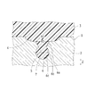
- FIG. 1 is an enlarged cross-sectional view schematically showing a joint portion in the joint structure 1 according to the present embodiment.
- the bonded structure 1 is obtained by bonding a first member 2 made of metal and a second member 3 made of resin.
- the first step perforated portion 4 that opens on the surface of the first member 2
- a second-stage perforated part 5 that opens in the first-stage perforated part 4 is formed.
- the second member 3 filled in the first-stage perforated part 4 and the second-stage perforated part 5 in the melted state is in the first-stage perforated part 4 and
- the 1st member 2 and the 2nd member 3 are joined by solidifying within the 2nd step perforation part 5.
- FIG. 1 only one set of the first-stage perforation part 4 and the second-stage perforation part 5 is shown to make the drawing easier to see, but in practice, the first-stage perforation part 4 and the second-stage perforation part 5 A plurality of sets 5 are formed.
- the metal material which comprises the 1st member 2 an iron-type metal, a stainless steel metal, a copper-type metal, an aluminum-type metal, a magnesium-type metal, and those alloys are mentioned.
- the first member 2 may be a metal molded body, or may be zinc die casting, aluminum die casting, powder metallurgy, or the like.
- the resin constituting the second member 3 is preferably a thermoplastic resin or a thermosetting resin.
- thermoplastic resins include PVC (polyvinyl chloride), PS (polystyrene), AS (acrylonitrile styrene), ABS (acrylonitrile butadiene styrene), PMMA (polymethyl methacrylate), PE (polyethylene), PP ( Polypropylene), PC (polycarbonate), m-PPE (modified polyphenylene ether), PA6 (polyamide 6), PA66 (polyamide 66), POM (polyacetal), PET (polyethylene terephthalate), PBT (polybutylene terephthalate), PSF (polysulfone) ), PAR (polyarylate), PEI (polyetherimide), PPS (polyphenylene sulfide), PES (polyethersulfone), PEEK (polyetheretherketone), PAI ( Riamidoimido
- the second member 3 may be TPE (thermoplastic elastomer), and examples of TPE include TPO (olefin-based), TPS (styrene-based), TPEE (ester-based), TPU (urethane-based), Examples include TPA (nylon-based) and TPVC (vinyl chloride-based).
- TPE thermoplastic elastomer
- examples of TPE include TPO (olefin-based), TPS (styrene-based), TPEE (ester-based), TPU (urethane-based), Examples include TPA (nylon-based) and TPVC (vinyl chloride-based).
- thermosetting resins examples include EP (epoxy), PUR (polyurethane), UF (urea formaldehyde), MF (melamine formaldehyde), PF (phenol formaldehyde), UP (unsaturated polyester) and SI (silicone). It is done.
- the second member 3 may be FRP (fiber reinforced plastic).
- a filler may be added to the thermoplastic resin and the thermosetting resin.
- the filler include inorganic fillers (glass fibers, inorganic salts, etc.), metal fillers, organic fillers, and carbon fibers.
- the first member 2 has a first-stage perforated portion 4 that communicates in the vertical direction (Z direction) with the surface side of the first member 2 as the upper side, as shown in FIG.
- the second-stage perforated portion 5 is formed.
- the second-stage perforated portion 5 is formed on the surface portion of the first member 2 when the first member 2 and the second member 3 are bonded to each other. This is to obtain a so-called anchor effect that is caused by filling the second-stage perforated portion 5 with 3) (also referred to as molten resin).
- the molten resin 3 becomes difficult to fill the second-stage perforated part 5, and the anchor effect may be reduced.
- FIG. 11 is a schematic diagram illustrating step by step how a melted second member (hereinafter also referred to as a molten resin) 103 is filled when the perforated portions 105a, 105b, and 105c that do not communicate with each other are formed. It is.
- a molten resin melted second member
- the molten resin 103 flows in the direction of the white arrow in FIG.
- the viscosity of the molten resin 103 is high and the force for pushing the molten resin 103 into the perforated portion 105a is insufficient, and therefore, as shown in FIG.
- the molten resin 103 is not filled in the perforated part 105a.
- the flow direction of the molten resin 103 is not the depth direction but the direction of the white arrow in FIG. 11B, the molten resin 103 may pass over the narrow perforated part 105a.
- the molten resin 103 may be filled into the perforated portion 105b, but there is no certainty as to whether or not it is filled.
- the perforated part 105a not filled with the second member 103, the perforated part 105b filled with the second member 103, and the second member 103 are filled.
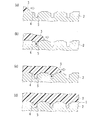
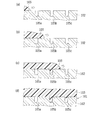
- FIG. 2 is a schematic diagram illustrating step by step how the molten resin 3 is filled in the case where the perforated portions 4 and 5 communicating in the vertical direction are formed.
- the throttle portion 7 in the second-stage perforating portion 5 is omitted for simplification of description.
- the perforated portions 4 and 5 communicating with the top and bottom are formed, even in the case where it is difficult to realize a high resin temperature and a high filling pressure, in the direction indicated by the white arrow in FIG.
- the molten resin 3 that has flowed is accumulated in the first-stage perforated portion 4 having a large opening area.
- the molten resin 3 accumulated in the first-stage perforated portion 4 does not flow in the direction of the white arrow in FIG. 2B (there is no place to go), and therefore is shown by the black arrow in FIG. Thus, it flows into the second stage perforation part 5. That is, when the perforated portions 4 and 5 communicating with each other are formed, the first-stage perforated portion 4 having a large opening area functions like a funnel with respect to the second-stage perforated portion 5 having a small opening area. As a result, the molten resin 3 is easily filled into the second-stage perforated portion 5. Thereby, in the joined structure 1, as shown in FIG.2 (d), the 2nd member 3 will be filled into the 2nd step drilling part 5.
- the first-stage perforation part 4 and the second-stage perforation part 5 are not simply communicated vertically, It is necessary that the opening area of the first stage punching part 4 is larger than the opening area of the second stage punching part 5. Therefore, in the present embodiment, the top surface of the first member 2 is vertically moved so that the opening area of the uppermost perforated portion (first-stage perforated portion 4) among the plurality of perforated portions 4 and 5 is maximized.
- the perforated portions 4 and 5 that communicate with each other are formed.
- various aspects can be considered as the aspect that “the opening area of the uppermost perforated portion among the plurality of perforated portions is maximized”, but in the present embodiment, a plurality of the surface portions of the first member 2 are arranged on the surface portion.
- the perforated portions 4 and 5 having circular openings are formed so that the opening diameter R1 of the uppermost perforated portion (first-stage perforated portion 4) among the perforated portions 4 and 5 is maximized. .
- the formation of the first-stage perforated part 4 causes the opening of the second-stage perforated part 5 to expand, but the inner diameter itself of the second-stage perforated part 5 does not increase, so that the joining surface
- the number of second-stage perforated portions 5 per unit area in the above does not decrease. Therefore, it is possible to suppress a decrease in the anchor effect while suppressing a decrease in yield and a decrease in bonding quality.
- These perforated portions 4 and 5 are formed by, for example, irradiating a processing laser beam (hereinafter simply referred to as a laser).
- a laser capable of pulse oscillation is preferable, and a fiber laser, a YAG laser, a YVO 4 laser, a semiconductor laser, a carbon dioxide gas laser, and an excimer laser can be selected.
- a fiber laser, a YAG laser, A second harmonic of a YAG laser, a YVO 4 laser, or a semiconductor laser is preferable.
- the first-stage perforated portion 4 is a non-through hole having a substantially circular cross section that opens on the surface of the first member 2, has a substantially dish shape, and a plurality of first-stage perforated portions 4 are formed on the surface portion of the first member 2.
- the opening diameter R1 of the first-stage perforated part 4 is preferably 50 ⁇ m or more and 400 ⁇ m or less. This is because when the opening diameter R1 is less than 50 ⁇ m, a high resin temperature and a high filling pressure also tend to be required for filling the first stage perforated part 4 with the molten resin, and the funnel which the first stage perforated part 4 plays a role. This is because the function may not be sufficiently expressed.
- the opening diameter R1 of the first step perforation part 4 exceeds 400 ⁇ m, in other words, if the first step perforation part 4 becomes too wide, the inner surface of the first step perforation part 4 and the surface of the first member 2 This is because the effect of inducing the flowing direction of the molten resin 3 in the depth direction due to the funnel function carried by the first-stage perforated portion 4 is sometimes reduced.
- the 1st step drilling part 4 bears a funnel function and the anchor effect is not desired, there is no restriction
- the first-stage perforated portion 4 for example, (1) a method using a laser having a large focal diameter (rather than the focal diameter of the laser used for processing the second-stage perforated portion 5), and (2) And a method of defocusing laser irradiation and enlarging the focal diameter.
- the method (2) for example, when the focal diameter of 50 ⁇ m is changed to a focal diameter of 100 ⁇ m by defocusing, the processing depth becomes shallower than the focal diameter of 50 ⁇ m because of insufficient energy.
- the first-stage perforated part 4 that takes on the funnel function has a wide and shallow shape, so there is no problem.
- the second-stage perforated portion 5 is a non-through hole having a substantially circular cross section that opens at the bottom surface of the first-stage perforated portion 4.
- the opening diameter R2 of the second-stage perforated part 5 is preferably 30 ⁇ m or more and 100 ⁇ m or less. This is because, even if the funnel function of the first-stage perforated part 4 appears, when the opening diameter R2 is less than 30 ⁇ m, the filling property of the molten resin 3 into the second-stage perforated part 5 is deteriorated and the bonding strength is reduced. This is because it may decrease. On the other hand, if the opening diameter R2 exceeds 100 ⁇ m, the number of second-stage perforated portions 5 per unit area may decrease and a desired bonding strength may not be obtained.
- the interval between the second-stage perforations 5 (the distance between the center of a certain second-stage perforation 5 and the center of the second-stage perforation 5 adjacent to the second-stage perforation 5) is 200 ⁇ m.
- the following is preferable. This is because if the interval between the second-stage perforated portions 5 exceeds 200 ⁇ m, the number of second-stage perforated portions 5 per unit area may decrease and a desired bonding strength may not be obtained.
- the second-stage perforated portion 5 is formed with a narrowed portion 7 in which the hole wall 6 is narrowed inward.
- the hole wall 6 of the second-stage perforated part 5 has a first wall part 6a that inclines inward in the depth direction (Z direction) from the surface side to the back side, and the back wall of the first wall part 6a.
- the second wall portion 6b that increases in diameter as it goes from the end on the side to the back side, and the third wall portion 6c that decreases in diameter as it goes from the end on the back side of the second wall portion 6b to the back side are connected.
- a portion where the first wall portion 6 a and the second wall portion 6 b are connected to each other constitutes the throttle portion 7.
- the narrowed portion 7 corresponds to the “projecting portion projecting inward” in the present invention, and the “projecting portion” extends over the entire circumference of the hole wall 6 of the second-stage perforated portion 5 having a substantially circular cross section. It is an example when formed.
- the dashed-two dotted line in FIG. 1 is a virtual line which shows the division of the 1st wall part 6a, the 2nd wall part 6b, and the 3rd wall part 6c.
- the second-stage perforated portion 5 is filled.
- the restricting portion 7 comes out of the second member 3 and is located behind the restricting portion 7, the joining strength in the peeling direction can be improved.
- the joining strength can be improved also in the peeling direction.
- the bonding strength can be maintained. Durability can be improved.
- the processing depth of the 2nd step drilling part 5 exceeds 30 ⁇ m.
- the second stage punching part 5 is formed by irradiating the bottom of the first stage punching part 4 with a laser in which one pulse is composed of a plurality of subpulses.
- a laser in which one pulse is composed of a plurality of subpulses.
- Such a system in which one pulse is irradiated with a laser composed of a plurality of sub-pulses is suitable for forming the second-stage perforated portion 5 because the energy of the laser is easily concentrated in the depth direction.
- the bottom of the first-stage perforated part 4 is irradiated with laser, the first member 2 is locally melted to advance the formation of the second-stage perforated part 5.
- the melted first member 2 is not easily scattered and easily deposited in the vicinity of the second-stage perforated portion 5.
- the melted first member 2 is deposited inside the second-stage perforated portion 5, thereby forming the throttle portion 7.
- fiber laser marker MX-Z2000 or MX-Z2050 manufactured by OMRON can be mentioned.
- one period of the sub-pulse is 15 ns or less. This is because when one period of the sub-pulse exceeds 15 ns, energy is easily diffused by heat conduction, and it is difficult to form the second-stage perforated portion 5.
- one cycle of the subpulse is a total time of the irradiation time for one subpulse and the interval from the end of the irradiation of the subpulse to the start of the irradiation of the next subpulse.
- the number of subpulses of one pulse is preferably 2 or more and 50 or less. This is because if the number of subpulses exceeds 50, the output per unit of subpulses becomes small, and it is difficult to form the second stage punching portion 5.
- the 2nd member 3 is joined to the surface of the 1st member 2 in which the 1st step punching part 4 and the 2nd step punching part 5 were formed by laser irradiation, injection molding, and hot press, for example.
- the second member 3 is joined to the first member 2 by being solidified in a state where it is melted by laser irradiation or the like and filled in the first-stage perforated part 4 and the second-stage perforated part 5. Yes.
- Such a bonded structure 1 is applicable, for example, when a resin cover (not shown) is bonded to a metal case (not shown) of a photoelectric sensor.
- the metal case corresponds to the first member 2
- the resin cover corresponds to the second member 3.
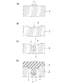
- the surface of the first member 2 is irradiated with a laser having a large focal diameter as shown in FIG. 3B.
- a substantially dish-shaped first-stage perforated portion 4 is formed (perforating step).
- the perforated part is arranged so that the second stage perforated part 5 communicates vertically with the first stage perforated part 4 having an opening area (opening diameter) larger than the opening area (opening diameter) of the second stage perforated part 5.
- 4 and 5 are formed by laser irradiation. Specifically, as shown by the white arrow in FIG. 3 (b), a laser having a small focal diameter is irradiated to the bottom of the first-stage perforated part 4, and as shown in FIG. 3 (c), the first A second step punching portion 5 is formed inside the step punching portion 4 (perforating step). At this time, the narrowed portion 7 is formed in the hole wall 6 of the second-stage punching portion 5 by irradiating a laser in which one pulse is composed of a plurality of subpulses.
- the spatter that has jumped out of the surface of the first member 2 by the laser irradiation for forming the first-stage perforated part 4 is formed.
- the previously formed second-stage perforated portion 5 may be blocked by the particles. For this reason, it is preferable to form the second-stage perforated part 5 after the first-stage perforated part 4 is formed first.
- the surface of the first member 2 is irradiated with a laser in a state where the first member 2 and the second member 3 are overlapped to melt the second member 3 (laser irradiation), or the first member 2 is made of gold.
- the molten resin 3 is injected into the mold (not shown) or injected (injection molding) to fill the first stage perforated portion 4 with the molten resin 3.
- the funnel function of the first-stage perforated part 4 causes the molten resin 3 to be in the second-stage perforated part as shown by the black arrow in FIG. Guided to 5.
- the filled molten resin 3 is solidified in the first-stage perforated part 4 and the second-stage perforated part 5, whereby the first member 2 and the second member 3 are joined, and the joining as shown in FIG. A structure 1 is formed.
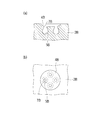
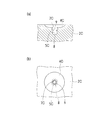
- FIGS. 4 (a) and 4 (b) are diagrams schematically illustrating a first member 2A according to Modification 1 of Embodiment 1
- FIG. 4A is a cross-sectional view
- FIG. 4B is a plan view.
- the shape of the second-stage perforated part 5A is different from that of the first embodiment.
- the second-stage perforated part 5A is formed in the first-stage perforated part 4A as in the second-stage perforated part 5 of the first embodiment.
- the throttle portion 7A is formed in the opening.
- the second-stage perforated portion 5A is formed in a simple shape such that the first wall portion 6a is omitted from the second-stage perforated portion 5 of the first embodiment. With such a configuration, it is possible to more easily form the perforated portions 4A and 5A communicating in the vertical direction while maintaining the improvement in the bonding strength in the peeling direction by the narrowed portion 7A.
- FIG. 5 is a diagram schematically illustrating a first member 2B in Modification 2 of Embodiment 1
- FIG. 5 (a) is a cross-sectional view
- FIG. 5 (b) is a plan view.
- This modified example 2 is different from the first embodiment in that the shape of the second-stage perforated part 5B and a plurality of second-stage perforated parts 5B are formed in one first-stage perforated part 4B.
- four second-stage perforated portions 5B are formed in the first-stage perforated portion 4B.
- each second-stage perforated portion 5B has an aperture portion 7B formed in the opening, as in the first modification.
- the molten resin 3 can be guided to the four second-stage perforations 5B by the funnel function of the first-stage perforations 4B.
- FIGS. 6A and 6B are diagrams schematically showing a first member 2C in Modification 3 of Embodiment 1
- FIG. 6A is a cross-sectional view
- FIG. 6B is a plan view.
- This modification 3 is different from the first embodiment in that the shape of the second-stage perforated part 5C and the perforated parts 4C, 5C, 8 are formed in three stages.
- the third-stage perforated portion 8 is formed in the second-stage perforated portion 5C.
- the second-stage perforated part 5C and the third-stage perforated part 8 have throttle parts 7C and 9 formed in the openings.
- the molten resin 3 can be guided to the second-stage perforated part 5C by the funnel function of the first-stage perforated part 4C, and the molten resin 3 is supplied by the funnel function of the second-stage perforated part 5C.
- the three-stage perforated part 8 can be guided.
- the opening diameter of the uppermost perforated portion is maximized is maximized as referred to in the present invention but also “the uppermost perforated portion” as referred to in the present invention.
- the lower perforated part is formed so that the opening diameter becomes smaller as going downward. Therefore, as a matter of course, in the present invention, not only the relationship that “the opening area of the uppermost perforated portion is maximized” but also the term “the upper perforated portion lower than the uppermost perforated portion” is referred to in the present invention. The relationship that the opening area becomes smaller as it goes downward is also satisfied.
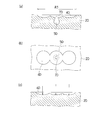
- FIGS. 7 (a) and 7 (b) are diagrams schematically showing a first member 2D in Modification 4 of Embodiment 1
- FIG. 7A is a cross-sectional view
- FIG. 7B is a plan view
- FIG. c) is a cross-sectional view illustrating a method of forming the first-stage perforated portion 4D.
- This modification 4 is different from the first embodiment in that the shape of the second-stage perforated part 5D and the plurality of first-stage perforated parts 4D are partially overlapped.
- this first member 2D as shown in FIGS. 7 (a) and 7 (b), three first-stage perforated portions 4D are formed so that the end portions overlap each other, and are connected in a straight line. Perforated portions 4D having an opening length R3 are formed.
- the second-stage perforated part 5D is formed in the middle first-stage perforated part 4D
- the narrowed part 7D is formed in the opening as in the first modification.
- the opening length R3 of the perforated portions 4D is not limited in the lower limit, but the upper limit is preferably 400 ⁇ m or less. This is because when the opening length R3 exceeds 400 ⁇ m, the effect of inviting the molten resin 3 in the depth direction by the funnel function performed by the first-stage perforated portion 4D decreases. .. Are formed by overlapping lasers during laser irradiation, as indicated by arrows in FIG. 7C. With such a configuration, it is possible to form the perforated portions 4D having a large opening area without irradiating a laser having a large focal diameter.
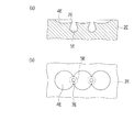
- FIGS. 8A and 8B are views schematically showing the first member 2E in Modification 5 of Embodiment 1
- FIG. 8A is a cross-sectional view
- FIG. 8B is a plan view.
- the fifth modification is different from the first embodiment in that a plurality of second-stage perforations 5E are formed in the shape of the second-stage perforations 5E and the perforations 4E formed of three first-stage perforations 4E. Are different.
- the three first-stage perforations 4E are formed so that the end portions overlap each other as in the fourth modification, and form perforations 4E,.
- two second-stage perforations 5E are formed in the perforations 4E,.
- each second-stage perforated portion 5E has an aperture portion 7E formed in the opening, as in the first modification.
- the molten resin 3 can be guided to the two second-stage perforations 5E by the funnel function of the perforations 4E,.
- the perforating portions 4E,... Having a large opening area are formed without irradiating a laser having a large focal diameter while maintaining the filling property of the second member 3 to the second stage perforating portion 5E. can do.
- first member 22 each having a length of 100 mm, a width of 29 mm, and a thickness of 3 mm, each made of stainless steel (SUS304), were prepared.
- the first member 22 is irradiated with a laser under the following laser irradiation condition 1 by using a fiber laser marker MX-Z2000 made by OMRON and irradiating a predetermined region R of 12.5 mm ⁇ 20.0 mm under the following laser irradiation condition 1.
- a stepped perforated portion was formed, and a second step perforated portion was formed by irradiating a laser under the following laser irradiation condition 2.
- the other first member 22 by irradiating the other first member 22 with a laser under the following laser irradiation condition 2 using the fiber laser marker MX-Z2000, it communicates vertically with a predetermined region R of 12.5 mm ⁇ 20.0 mm. Only an unperforated portion (hereinafter referred to as a second-stage perforated portion for convenience) was formed.
- the frequency for forming the second stage perforated part was a pulse frequency composed of 20 subpulses. That is, under this irradiation condition 2, laser (pulse) was irradiated 10,000 times at an interval of 65 ⁇ m while moving 650 mm per second, and the pulse was composed of 20 subpulses. In this way, a second stage perforated part having a throttle part on the surface of the first member 22 was formed by irradiating a laser composed of 20 sub-pulses per pulse.
- the frequency at the time of forming the first-stage perforated part was set to a pulse frequency composed of seven sub-pulses in order to reduce the depth of the first-stage perforated part.
- the irradiation interval when forming the first-stage perforations was 40 ⁇ m so that the ends of the adjacent first-stage perforations overlap each other.
- the first member 22 has a perforated portion in which the first-stage perforated portions having an opening diameter of 40 to 50 ⁇ m are linearly connected as in the fourth modification of the first embodiment.
- the joined structure 21 in which the second member 23 is joined to the predetermined region R is formed by insert molding on the first member 22 in which the first and second step perforated portions are formed.
- a bonded structure 21 in which the second member 23 was bonded to the predetermined region R was manufactured by insert molding with respect to the first member 22 in which only the second-stage perforated portion was formed.
- the second member 23 uses polybutylene terephthalate (PBT) (Juranex (registered trademark) 3316 manufactured by Wintech Polymer) as a material, and is 100 mm long ⁇ 25 mm wide ⁇ 3 mm thick. Molded into a plate.
- J35EL3 made from Japan Steel Works was used for the molding machine. The molding conditions are as follows.
- ⁇ Molding conditions> Pre-drying: 120 ° C x 5 hours Mold temperature: 80 ° C Cylinder temperature: 270 ° C Holding pressure: 20 MPa
- the mold temperature is set to 80. While the temperature was set to a relatively low temperature, the holding pressure was set to a relatively low pressure of 20 MPa.
- Example 1 and Comparative Example 1 produced as described above, the bonding strength was measured using an electromechanical universal testing machine 5900 manufactured by Instron. Specifically, the test is performed at a tensile speed of 5 mm / min in the shear direction (direction parallel to the joint surface), and the second member 23 is broken or the joint interface is broken (peeling between the first member 22 and the second member 23). ) Ended the test. The maximum strength obtained was adopted as the bonding strength. Table 1 shows the bonding strengths obtained for Example 1 and Comparative Example 1.
- Example 1 in which the first and second-stage perforations were formed, the bonding strength was improved nearly three times as compared with Comparative Example 1 in which only the second-stage perforations were formed.
- the first-stage perforated portion having a shallow working depth hardly contributes to the anchor effect.
- Example 1 is a comparative example.
- the reason why the bonding strength is improved by nearly three times as compared to 1 is considered to be that the filling rate of the second member 23 into the second-stage perforated part is increased by the funnel function of the first-stage perforated part.
- the perforated portion communicating with the top and bottom contributes to the improvement of the bonding strength.
- the present embodiment is different from the first embodiment in that the first member 12 is also made of resin.
- the first member 12 is also made of resin.
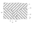
- FIG. 10 is an enlarged cross-sectional view schematically showing a joint portion in the joint structure 11 according to the present embodiment.
- the bonded structure 11 is formed by bonding a first member 12 and a second member 3 made of different resin materials.
- a first step perforated portion 14 that opens on the surface of the first member 12
- a second-stage perforated part 15 that opens in the first-stage perforated part 14 is formed.
- the second member 3 filled in the first-stage perforated part 14 and the second-stage perforated part 15 in the melted state is contained in the first-stage perforated part 14 and the first-stage perforated part 14.
- the first member 12 and the second member 3 are joined by solidifying in the two-stage perforated portion 15.
- FIG. 10 only one set of the first-stage perforation part 14 and the second-stage perforation part 15 is shown in order to make the drawing easier to see, but actually, the first-stage perforation part 14 and the second-stage perforation part 14 A plurality of sets 15 are formed.
- the resin constituting the first member 12 is preferably a thermoplastic resin or a thermosetting resin.
- the types of the thermoplastic resin and the thermosetting resin that constitute the first member 12 are the same as the thermoplastic resin and the thermosetting resin that constitute the second member 3 shown in the first embodiment. Further, similar to the second member 3, a filler may be added to the thermoplastic resin and the thermosetting resin.
- the first-stage perforated part 14 and the second-stage perforated part 15 are formed by irradiating laser as in the first embodiment.
- the narrowed portion 17 can be formed in the hole wall 16 of the second-stage punched portion 15 by irradiating a laser in which one pulse is composed of a plurality of subpulses.
- the first-stage perforated portion 14 and the second-stage perforated portion are formed in the shapes as shown in FIGS.
- the part 15 can be formed.
- the first member 32 is irradiated with a laser under the following laser irradiation condition 1 by using a fiber laser marker MX-Z2000 made by OMRON and irradiating a predetermined region R of 12.5 mm ⁇ 20.0 mm under the following laser irradiation condition 1.
- a stepped perforated portion was formed, and a second step perforated portion was formed by irradiating a laser under the following laser irradiation condition 2.
- the other first member 32 with a laser under the following laser irradiation condition 2 using the fiber laser marker MX-Z2000, it communicates vertically with a predetermined region R of 12.5 mm ⁇ 20.0 mm. Only an unperforated portion (hereinafter referred to as a second-stage perforated portion for convenience) was formed.
- the scanning for forming the first-stage perforated part is performed.
- the number of times was set as small as 1 time.
- a second-stage perforated part having a constricted part on the surface part of the first member 32 is formed by irradiating a laser in which one pulse is composed of five sub-pulses. did.
- the frequency at the time of forming the first-stage perforated part is a pulse frequency constituted by three sub-pulses in order to reduce the depth of the first-stage perforated part.
- the irradiation interval when forming the first-stage perforations was 40 ⁇ m so that the ends of the adjacent first-stage perforations overlap each other.
- the joined structure 31 in which the second member 33 is joined to the predetermined region R is formed by insert molding on the first member 32 in which the first and second step perforated portions are formed.
- This is used as Example 2, and a joined structure 31 is produced in which the second member 33 is joined to the predetermined region R with respect to the first member 32 in which only the second-stage perforated portion is formed.
- the second member 33 is made of polybutylene terephthalate (PBT) (Juranex (registered trademark) 3316 made by Wintech Polymer) as a material for both Example 2 and Comparative Example 2, and is 100 mm long ⁇ 25 mm wide ⁇ 3 mm thick. Molded into a plate.
- J35EL3 made from Japan Steel Works was used for the molding machine. The molding conditions are as follows.
- Example 2 in which the first and second-stage perforations were formed, the bonding strength was improved nearly three times as compared with Comparative Example 2 in which only the second-stage perforations were formed. Thereby, also in the joining structure 31 which joined resin, it was able to confirm that the perforated part connected up and down contributed to the improvement of joining strength.
- the second-stage perforated portions 5, 5A, 5B, 5C, 5D, and 5E having the narrowed portions 7, 7A, 7B, 7C, 7D, and 7E are formed.
- the shape of the perforated part in the second and subsequent stages may be a straight shape having no throttle part.
- the third-stage perforated portion 8 is formed.
- the present invention is not limited to this, and a fourth-stage perforated portion may be formed.
- the perforated portions 5C and 8 below the first stage perforated part 4C are formed so that the opening diameter (opening area) decreases as going downward, but the first stage perforated part If it is formed so that the opening diameter (opening area) of 4C is maximized, the present invention is not limited to this.
- the opening diameter (opening area) of the second stage punching part 5C and the third stage punching part 8 The opening diameter (opening area) may be the same.
- the present invention even when it is difficult to achieve a high resin temperature and a high filling pressure, it is possible to suppress a decrease in yield and a decrease in bonding quality, and thus a method for manufacturing a bonded structure in which different types of members are bonded to each other And is very useful when applied to bonded structures.
Landscapes
- Engineering & Computer Science (AREA)
- Mechanical Engineering (AREA)
- Physics & Mathematics (AREA)
- Optics & Photonics (AREA)
- Plasma & Fusion (AREA)
- Manufacturing & Machinery (AREA)
- Electromagnetism (AREA)
- Toxicology (AREA)
- Health & Medical Sciences (AREA)
- Thermal Sciences (AREA)
- Lining Or Joining Of Plastics Or The Like (AREA)
- Laser Beam Processing (AREA)
- Injection Moulding Of Plastics Or The Like (AREA)
Abstract
第1部材と、樹脂からなる第2部材とが接合された接合構造体の製造方法、および、第1部材と第2部材とが接合された接合構造体である。接合構造体の製造方法は、第2部材との接合面を構成する第1部材の表面部に、当該第1部材の表面側を上側として上下に連通する第1および第2段穿孔部を、当該第1および第2段穿孔部のうち最上段の第1段穿孔部の開口面積が最大となるように、レーザを照射することにより形成する穿孔工程と、第1および第2段穿孔部に第2部材を充填することにより、第1部材と第2部材とを接合する接合工程と、を含む。接合構造体は、第1部材の表面部に上下に連通する複数の穿孔部が、最上段の穿孔部の開口面積が最大となるように、レーザを照射することによって形成されており、複数の穿孔部に第2部材が充填されている。
Description
本発明は、接合構造体の製造方法および接合構造体に関するものである。
従来から、異種材料からなる部材同士を接合させた接合構造体が知られている。このような接合構造体では、本来接合し難い異種部材同士を接合していることから、その接合強度を高めることが一つの課題になっている。
例えば、特許文献1には、金属成形体における樹脂成形体との接合面に対して、開口部の平均直径が0.01~50μmの凹部または平均幅が0.01~50μmの溝を形成する第1工程と、凹部または溝が形成された接合面に対して、開口部の平均直径が1.0~1000μm、最大深さが10~1000μmの凹部または平均幅が1.0~1000μm、最大深さが10~1000μmの溝を形成する第2工程と、インサート成形により複合成形体を得る第3工程と、を有する複合成形体の製造方法が開示されている。この特許文献1のものによれば、接合強度を高めることができるとされている。
ところで、接合構造体において、一方の部材における他方の部材との接合部に凹部を形成するのは、両者を接合する際に溶融した他方の部材(例えば樹脂部材)が凹部に充填されることで生じる、いわゆるアンカー効果を得るためであることが多い。
そして、上記特許文献1には、接合強度が向上する理由は記載されていないが、特許文献1の図4~図8から、金属部材における接合面全体に同一の形状パターンで1.0~1000μm、最大深さが10~1000μmの凹部等を形成し、かかる凹部等に樹脂を充填することで接合強度を高めていると考えられる。
もっとも、凹部の開口部が狭小である場合には、溶融した樹脂部材(以下、溶融樹脂ともいう)が凹部に充填され難くなり、アンカー効果が減少するおそれがある。ここで、溶融樹脂が凹部に充填され易くなるように、凹部の寸法を大きくすることも考えられるが、この場合には、接合面における単位面積当たりの凹部の数が減少するため、却ってアンカー効果が減少するおそれがある。このため、アンカー効果を減少させることなく、溶融樹脂を開口部が狭小な凹部に充填するには、粘度を低くするための高い樹脂温度と、狭小な凹部に樹脂を押し込むための高い充填圧力とが要求されることになる。
しかしながら、樹脂の中には高温になると分解するものがあるため、高い樹脂温度を実現することが困難な場合がある。また、比較的サイズの小さい接合構造体を製造する際には、充填圧力の低い設備を用いることが一般的であるため、既存の設備との関係で高い充填圧力を実現することが困難な場合がある。このため、上記特許文献1のもののように、単に接合面全体に凹部等を形成するだけでは、高い樹脂温度や高い充填圧力を実現することが困難な場合に、樹脂が凹部等に充填されず、接合構造体の歩留まりが低下するおそれや、樹脂が充填された凹部等と充填されていない凹部等とが生じることで接合強度のバラツキ等が発生して、接合品質が低下するおそれがある。
本発明はかかる点に鑑みてなされたものであり、その目的とするところは、接合構造体の製造方法および接合構造体において、高い樹脂温度および高い充填圧力を実現することが困難な場合でも、歩留まりの低下および接合品質の低下を抑える技術を提供することにある。
前記目的を達成するため、本発明に係る接合構造体の製造方法および接合構造体では、一方の部材における他方の部材との接合部に設けられる穿孔部を、溶融樹脂を導き易い形状に形成するようにしている。
具体的には、本発明は、第1部材と、樹脂からなる第2部材とが接合された接合構造体の製造方法であって、前記第2部材との接合面を構成する前記第1部材の表面部に、当該第1部材の表面側を上側として上下に連通する複数の穿孔部を、当該複数の穿孔部のうち最上段の穿孔部の開口面積が最大となるように、レーザを照射することにより形成する穿孔工程と、前記複数の穿孔部に前記第2部材を充填することにより、当該第1部材と当該第2部材とを接合する接合工程と、を含むことを特徴とするものである。
この構成によれば、上下に連通する複数の穿孔部のうち最上段の穿孔部(仮に第1の穿孔部ともいう)の開口面積が最大となるように複数の穿孔部が形成されるので、大きな開口面積を有する第1の穿孔部が、これよりも下方の穿孔部(仮に第2の穿孔部ともいう)に対し、恰も漏斗のように機能することになり、溶融された第2部材(以下、溶融樹脂ともいう)が第2の穿孔部に充填され易くなる。
より詳しくは、仮に開口面積の小さい第2の穿孔部しか形成されておらず、かつ、溶融樹脂の粘度が高く、充填圧力が低い場合には、溶融樹脂が入口の狭い第2の穿孔部内に流れ込まないおそれがある。これに対し、開口面積の大きい第1の穿孔部を形成すれば、溶融樹脂の粘度が高くかつ充填圧力が低い場合でも、溶融樹脂が入口の広い第1の穿孔部内に流れ込み易くなるとともに、第1の穿孔部内に溜まった溶融樹脂がさらに第2の穿孔部内に流れ込み易くなる。これにより、高い樹脂温度および高い充填圧力を実現することが困難な場合でも、第2の穿孔部内に溶融樹脂が確実に充填されるので、歩留まりの低下および接合品質の低下を抑えることができる。
また、第1の穿孔部により、アンカー効果を担う第2の穿孔部の開口部が恰も拡大するようになるが、第2の穿孔部の内空自体が大きくなる訳ではないので、接合面における単位面積当たりの第2の穿孔部の数は減少しない。よって、歩留まりの低下および接合品質の低下を抑えつつ、アンカー効果が減少するのを抑えることができる。
なお、本発明において「上下に連通する複数の穿孔部」とは、1つの第1の穿孔部の下方に1つの第2の穿孔部が形成される場合のみならず、例えば、1つの第1の穿孔部の下方に複数の第2の穿孔部が形成される場合や、第1の穿孔部の下方に形成された第2の穿孔部の下方に、さらに第3以降の穿孔部が形成される場合を含むものである。
また、第1の穿孔部は、単独である必要はなく、複数の第1の穿孔部を一部重畳させて形成された穿孔部の下方に第2以降の穿孔部を形成してもよい。同様に、第2以降の穿孔部も、単独である必要はなく、複数の第2以降の穿孔部を一部重畳させた穿孔部を形成してもよい。
前記接合構造体の製造方法において、前記穿孔工程では、前記複数の穿孔部のうち最上段の穿孔部よりも下方の穿孔部を、下方に行くにしたがって開口面積が小さくなるように形成することが好ましい。
この構成によれば、例えば第2の穿孔部が第3の穿孔部に対し恰も漏斗のように機能するというように、下方の穿孔部に対して漏斗機能を有する穿孔部が連なることになるので、溶融樹脂が上下に連通するすべての穿孔部に充填され易くなる。
そうして、「最上段の穿孔部の開口面積が最大となる」態様の1つとして、前記接合構造体の製造方法において、前記穿孔工程では、前記最上段の穿孔部の開口径が最大となるように、前記複数の穿孔部を形成することが好ましい。
この構成によっても、大きな開口径を有する第1の穿孔部が、第2の穿孔部に対し、恰も漏斗のように機能することから、高い樹脂温度および高い充填圧力を実現することが困難な場合でも、第2の穿孔部内に溶融樹脂が確実に充填されるので、歩留まりの低下および接合品質の低下を抑えることができる。
また、最上段の穿孔部の開口径が最大となるように複数の穿孔部を形成する場合には、前記接合構造体の製造方法において、前記穿孔工程では、前記複数の穿孔部のうち最上段の穿孔部よりも下方の穿孔部を、下方に行くにしたがって開口径が小さくなるように形成することが好ましい。
この構成によれば、下方の穿孔部に対して漏斗機能を有する穿孔部が連なることになるので、溶融樹脂が上下に連通するすべての穿孔部に充填され易くなる。
前記接合構造体の製造方法において、前記穿孔工程では、1パルスが複数のサブパルスから構成されるレーザを照射することにより、前記最上段の穿孔部よりも下方の穿孔部の孔壁に内側に突出する突出部を形成することが好ましい。
この構成によれば、照射されるレーザが複数のサブパルスで構成されているため、溶融された第1部材が飛散され難く、第2以降の穿孔部の内部に堆積されることから、第2以降の穿孔部の孔壁に内側に突出する突出部を形成することができる。これにより、第2部材を第1部材から剥離するような力が作用した場合でも、穿孔部に充填された第2部材のうち突出部よりも奥側の部位に対して、突出部が抜け出し抵抗となることから、剥離方向の接合強度の向上を図ることができる。
前記接合構造体の製造方法において、前記第1部材は、金属、熱可塑性樹脂または熱硬化性樹脂からなることが好ましい。
前記接合構造体の製造方法において、前記第2部材は、熱可塑性樹脂または熱硬化性樹脂からなることが好ましい。
前記接合構造体の製造方法において、前記接合工程では、レーザ照射、射出成型または熱プレスにより、前記複数の穿孔部に前記第2部材を充填することが好ましい。
また、本発明は、第1部材と第2部材とが接合された接合構造体をも対象としている。
具体的には、本発明は、第1部材と、樹脂からなる第2部材とが接合された接合構造体であって、前記第2部材との接合面を構成する前記第1部材の表面部に、当該第1部材の表面側を上側として上下に連通する複数の穿孔部が、当該複数の穿孔部のうち最上段の穿孔部の開口面積が最大となるように、レーザを照射することによって形成されており、前記複数の穿孔部に前記第2部材が充填されていることを特徴とするものである。
この構成によれば、大きな開口面積を有する第1の穿孔部が、第2の穿孔部に対し恰も漏斗のように機能することから、高い樹脂温度および高い充填圧力を実現することが困難な場合でも、第2の穿孔部内に溶融樹脂が確実に充填されるので、歩留まりの低下および接合品質の低下を抑えることができる。
以上、説明したように本発明に係る接合構造体の製造方法および接合構造体によれば、高い樹脂温度および高い充填圧力を実現することが困難な場合でも、歩留まりの低下および接合品質の低下を抑えることができる。
以下、本発明を実施するための形態を図面に基づいて説明する。
(実施形態1)
-接合構造体の全体構成-
図1は、本実施形態に係る接合構造体1における接合部を模式的に示す拡大断面図である。この接合構造体1は、図1に示すように、金属からなる第1部材2と、樹脂からなる第2部材3とが接合されたものである。接合構造体1における第1部材2と第2部材3との接合界面を構成する第1部材2の表面部には、当該第1部材2の表面で開口する第1段穿孔部4と、当該第1段穿孔部4内で開口する第2段穿孔部5と、が形成されている。そうして、この接合構造体1では、溶融された状態で、これら第1段穿孔部4および第2段穿孔部5に充填された第2部材3が、これら第1段穿孔部4内および第2段穿孔部5内で固化することで、第1部材2と第2部材3とが接合されている。なお、図1では、図を見易くするために、第1段穿孔部4および第2段穿孔部5を1組だけ示しているが、実際には第1段穿孔部4および第2段穿孔部5は複数組形成されている。
-接合構造体の全体構成-
図1は、本実施形態に係る接合構造体1における接合部を模式的に示す拡大断面図である。この接合構造体1は、図1に示すように、金属からなる第1部材2と、樹脂からなる第2部材3とが接合されたものである。接合構造体1における第1部材2と第2部材3との接合界面を構成する第1部材2の表面部には、当該第1部材2の表面で開口する第1段穿孔部4と、当該第1段穿孔部4内で開口する第2段穿孔部5と、が形成されている。そうして、この接合構造体1では、溶融された状態で、これら第1段穿孔部4および第2段穿孔部5に充填された第2部材3が、これら第1段穿孔部4内および第2段穿孔部5内で固化することで、第1部材2と第2部材3とが接合されている。なお、図1では、図を見易くするために、第1段穿孔部4および第2段穿孔部5を1組だけ示しているが、実際には第1段穿孔部4および第2段穿孔部5は複数組形成されている。
-第1部材および第2部材-
第1部材2を構成する金属材料の一例としては、鉄系金属、ステンレス系金属、銅系金属、アルミニウム系金属、マグネシウム系金属およびそれらの合金が挙げられる。また、第1部材2は、金属成型体であってもよく、亜鉛ダイカスト、アルミダイカスト、粉末冶金などであってもよい。
第1部材2を構成する金属材料の一例としては、鉄系金属、ステンレス系金属、銅系金属、アルミニウム系金属、マグネシウム系金属およびそれらの合金が挙げられる。また、第1部材2は、金属成型体であってもよく、亜鉛ダイカスト、アルミダイカスト、粉末冶金などであってもよい。
一方、第2部材3を構成する樹脂は、熱可塑性樹脂または熱硬化性樹脂であることが好ましい。熱可塑性樹脂の一例としては、PVC(ポリ塩化ビニル)、PS(ポリスチレン)、AS(アクリロニトリル・スチレン)、ABS(アクリロニトリル・ブタジエン・スチレン)、PMMA(ポリメチルメタクリレート)、PE(ポリエチレン)、PP(ポリプロピレン)、PC(ポリカーボネート)、m-PPE(変性ポリフェニレンエーテル)、PA6(ポリアミド6)、PA66(ポリアミド66)、POM(ポリアセタール)、PET(ポリエチレンテレフタレート)、PBT(ポリブチレンテレフタレート)、PSF(ポリサルホン)、PAR(ポリアリレート)、PEI(ポリエーテルイミド)、PPS(ポリフェニレンサルファイド)、PES(ポリエーテルサルホン)、PEEK(ポリエーテルエーテルケトン)、PAI(ポリアミドイミド)、LCP(液晶ポリマー)、PVDC(ポリ塩化ビニリデン)、PTFE(ポリテトラフルオロエチレン)、PCTFE(ポリクロロトリフルオロエチレン)およびPVDF(ポリフッ化ビニリデン)が挙げられる。また、第2部材3は、TPE(熱可塑性エラストマ)であってもよく、TPEの一例としては、TPO(オレフィン系)、TPS(スチレン系)、TPEE(エステル系)、TPU(ウレタン系)、TPA(ナイロン系)およびTPVC(塩化ビニル系)が挙げられる。
熱硬化性樹脂の一例としては、EP(エポキシ)、PUR(ポリウレタン)、UF(ユリアホルムアルデヒド)、MF(メラミンホルムアルデヒド)、PF(フェノールホルムアルデヒド)、UP(不飽和ポリエステル)およびSI(シリコーン)が挙げられる。また、第2部材3は、FRP(繊維強化プラスチック)であってもよい。
なお、これら熱可塑性樹脂および熱硬化性樹脂には、充填剤が添加されていてもよい。充填剤の一例としては、無機系充填剤(ガラス繊維、無機塩類など)、金属系充填剤、有機系充填剤および炭素繊維などが挙げられる。
-穿孔部-
本実施形態では、第1部材2の表面部に、図1に示すように、第1部材2の表面側を上側として上下(Z方向)に連通する(連なる)、第1段穿孔部4と第2段穿孔部5とを形成している。先ず、このように上下に連通する穿孔部4,5を形成している理由について説明する。
本実施形態では、第1部材2の表面部に、図1に示すように、第1部材2の表面側を上側として上下(Z方向)に連通する(連なる)、第1段穿孔部4と第2段穿孔部5とを形成している。先ず、このように上下に連通する穿孔部4,5を形成している理由について説明する。
接合構造体1において、第1部材2の表面部に第2段穿孔部5を形成するのは、第1部材2と第2部材3とを接合する際に、溶融した第2部材(以下、溶融樹脂ともいう)3が第2段穿孔部5に充填されることで生じる、いわゆるアンカー効果を得るためである。
もっとも、第2段穿孔部5の開口部が狭小である場合には、溶融樹脂3が第2段穿孔部5に充填され難くなり、アンカー効果が減少する場合がある。ここで、溶融樹脂3が第2段穿孔部5に充填され易くなるように、第2段穿孔部5の孔径を大きくすることも考えられるが、この場合には、接合面における単位面積当たりの第2段穿孔部5の数が減少するため、却ってアンカー効果が減少する場合がある。このため、アンカー効果を減少させることなく、溶融樹脂3を開口部が狭小な第2段穿孔部5に充填するには、粘度を低くするための高い樹脂温度と、狭小な第2段穿孔部5に溶融樹脂3を押し込むための高い充填圧力とが要求される。
しかしながら、樹脂の中には高温になると分解するものがあるため、高い樹脂温度を実現することが困難な場合がある。また、比較的サイズの小さい接合構造体1を製造する際には、充填圧力の低い設備を用いることが一般的であるため、既存の設備との関係で高い充填圧力を実現することが困難な場合がある。
図11は、上下に連通しない穿孔部105a,105b,105cが形成された場合における、溶融された第2部材(以下、溶融樹脂ともいう)103が充填される様子を段階的に説明する模式図である。例えば、インサート成形により第1部材102と第2部材103とを接合する場合には、図11(a)の白抜き矢印の方向に溶融樹脂103が流れてくる。そして、高い樹脂温度および高い充填圧力を実現することが困難な場合には、溶融樹脂103の粘性が高く且つ溶融樹脂103を穿孔部105aに押し込む力が不足するため、図11(b)に示すように、溶融樹脂103が穿孔部105aに充填されないおそれがある。換言すると、溶融樹脂103の流れの向きは、深さ方向ではなく、図11(b)の白抜き矢印の方向になるため、溶融樹脂103が入口の狭い穿孔部105aを跨いで通り過ぎて行くおそれがある。また、図11(c)に示すように、溶融樹脂103が穿孔部105bに充填されることもあるが、充填される否かに確実性がない。このため、接合構造体101において、図11(d)に示すように、第2部材103が充填されない穿孔部105aや、第2部材103が充填された穿孔部105bや、第2部材103の充填が不十分な穿孔部105cが生じるおそれがある。このように、第2部材103が充填された穿孔部105bと充填されていない穿孔部105a,105cとが生じると、接合強度のバラツキ等が発生して、接合品質が低下するおそれがあり、最悪の場合には製品として成り立たず、歩留まりが低下するおそれがある。
一方、図2は、上下に連通する穿孔部4,5が形成された場合における、溶融樹脂3が充填される様子を段階的に説明する模式図である。なお、図2では説明の簡略化のために第2段穿孔部5における絞り部7を省略している。これに対し、上下に連通する穿孔部4,5が形成されていると、高い樹脂温度および高い充填圧力を実現することが困難な場合でも、図2(a)の白抜き矢印で示す方向に流れてきた溶融樹脂3は、図2(b)に示すように、開口面積の大きい第1段穿孔部4に溜まることになる。このように、第1段穿孔部4に溜まった溶融樹脂3は、図2(b)の白抜き矢印の方向に流れない(行き場がない)ため、図2(c)の黒塗り矢印に示すように、第2段穿孔部5に流れ込むことになる。つまり、上下に連通する穿孔部4,5が形成された場合には、開口面積の大きい第1段穿孔部4が、開口面積の小さい第2段穿孔部5に対し、恰も漏斗のように機能することになり、溶融樹脂3が第2段穿孔部5に充填され易くなる。これにより、接合構造体1において、図2(d)に示すように、第2部材3が第2段穿孔部5に充填されることになる。
このような第2段穿孔部5に対する第1段穿孔部4の漏斗機能を得るためには、第1段穿孔部4と第2段穿孔部5とが、単に上下に連通するだけではなく、第1段穿孔部4の開口面積が第2段穿孔部5の開口面積よりも大きいことが必要となる。そこで、本実施形態では、第1部材2の表面部に、複数の穿孔部4,5のうち最上段の穿孔部(第1段穿孔部4)の開口面積が最大となるように、上下に連通する穿孔部4,5を形成するようにしている。
ここで、「複数の穿孔部のうち最上段の穿孔部の開口面積が最大となる」態様としては様々なものが考えられるが、本実施形態では、第1部材2の表面部に、複数の穿孔部4,5のうち最上段の穿孔部(第1段穿孔部4)の開口径R1が最大となるように、円形状の開口部を有する穿孔部4,5を形成するようにしている。
そして、第1段穿孔部4の形成により、恰も第2段穿孔部5の開口部が拡大するようになるが、第2段穿孔部5の内部径自体が大きくなる訳ではないので、接合面における単位面積当たりの第2段穿孔部5の数は減少しない。よって、歩留まりの低下および接合品質の低下を抑えつつ、アンカー効果が減少するのを抑えることができる。
これらの穿孔部4,5は、例えば、加工用のレーザ光(以下、単にレーザという)が照射されることによって形成される。レーザの種類としては、パルス発振が可能なものが好ましく、ファイバレーザ、YAGレーザ、YVO4レーザ、半導体レーザ、炭酸ガスレーザ、エキシマレーザが選択でき、レーザの波長を考慮すると、ファイバレーザ、YAGレーザ、YAGレーザの第2高調波、YVO4レーザ、半導体レーザが好ましい。
[第1段穿孔部]
第1段穿孔部4は、第1部材2の表面で開口する横断面略円形の非貫通孔であり、略皿状をなしていて、第1部材2の表面部に複数形成されている。第1段穿孔部4の開口径R1は、50μm以上、400μm以下が好ましい。これは、開口径R1が50μm未満では、当該第1段穿孔部4への溶融樹脂の充填にも高い樹脂温度および高い充填圧力を必要とする傾向にあり、第1段穿孔部4が担う漏斗機能が十分に発現されない場合があるからである。また、第1段穿孔部4の開口径R1が400μmを超えると、換言すると、第1段穿孔部4が広くなり過ぎると、第1段穿孔部4の内面と第1部材2の表面とに大差がなくなり、第1段穿孔部4が担う漏斗機能による、溶融樹脂3の流れる方向を深さ方向へ誘う効果が減少する場合があるからである。なお、第1段穿孔部4は、漏斗機能を担い、アンカー効果は望まれていないので、その加工深さに特に制限はない。
第1段穿孔部4は、第1部材2の表面で開口する横断面略円形の非貫通孔であり、略皿状をなしていて、第1部材2の表面部に複数形成されている。第1段穿孔部4の開口径R1は、50μm以上、400μm以下が好ましい。これは、開口径R1が50μm未満では、当該第1段穿孔部4への溶融樹脂の充填にも高い樹脂温度および高い充填圧力を必要とする傾向にあり、第1段穿孔部4が担う漏斗機能が十分に発現されない場合があるからである。また、第1段穿孔部4の開口径R1が400μmを超えると、換言すると、第1段穿孔部4が広くなり過ぎると、第1段穿孔部4の内面と第1部材2の表面とに大差がなくなり、第1段穿孔部4が担う漏斗機能による、溶融樹脂3の流れる方向を深さ方向へ誘う効果が減少する場合があるからである。なお、第1段穿孔部4は、漏斗機能を担い、アンカー効果は望まれていないので、その加工深さに特に制限はない。
第1段穿孔部4の形成手法としては、例えば、(1)(第2段穿孔部5を加工するのに用いるレーザの焦点径よりも)焦点径の大きいレーザを用いる手法と、(2)レーザ照射をデフォーカスして、焦点径を拡大する手法とが挙げられる。なお、(2)の手法において、例えば、50μmの焦点径をデフォーカスにより100μmの焦点径にした場合には、エネルギが不足するため50μmの焦点径に比して加工深さが浅くなるが、漏斗機能を担う第1段穿孔部4は広く浅い形状が好ましいので、問題はない。
[第2段穿孔部]
第2段穿孔部5は、第1段穿孔部4の底面で開口する横断面略円形の非貫通孔である。第2段穿孔部5の開口径R2は、30μm以上、100μm以下が好ましい。これは、第1段穿孔部4の漏斗機能が発現しても、開口径R2が30μm未満の場合には、溶融樹脂3の第2段穿孔部5への充填性が悪化して接合強度が低下する場合があるからである。一方、開口径R2が100μmを超えると、単位面積あたりの第2段穿孔部5の数が減少して所望の接合強度が得られない場合があるからである。
第2段穿孔部5は、第1段穿孔部4の底面で開口する横断面略円形の非貫通孔である。第2段穿孔部5の開口径R2は、30μm以上、100μm以下が好ましい。これは、第1段穿孔部4の漏斗機能が発現しても、開口径R2が30μm未満の場合には、溶融樹脂3の第2段穿孔部5への充填性が悪化して接合強度が低下する場合があるからである。一方、開口径R2が100μmを超えると、単位面積あたりの第2段穿孔部5の数が減少して所望の接合強度が得られない場合があるからである。
また、第2段穿孔部5の間隔(或る第2段穿孔部5の中心と、当該或る第2段穿孔部5と隣接する第2段穿孔部5の中心との距離)は、200μm以下であることが好ましい。これは、第2段穿孔部5の間隔が200μmを超えると、単位面積あたりの第2段穿孔部5の数が減少して所望の接合強度が得られない場合があるからである。
この第2段穿孔部5には、図1に示すように、孔壁6を内側に絞ったような絞り部7が形成されている。換言すると、第2段穿孔部5の孔壁6は、深さ方向(Z方向)において、表面側から奥側に行くほど内側に傾斜する第1壁部6aと、第1壁部6aの奥側の端部から奥側に行くほど拡径する第2壁部6bと、第2壁部6bの奥側の端部から奥側に行くほど縮径する第3壁部6cとが連なるように形成されていて、第1壁部6aと第2壁部6bとが繋がる部分が絞り部7を構成している。なお、絞り部7は、本発明でいうところの「内側に突出する突出部」に相当し、「突出部」が横断面略円形の第2段穿孔部5の孔壁6の全周に亘って形成された場合の一例である。なお、図1における二点鎖線は、第1壁部6a、第2壁部6bおよび第3壁部6cの区分を示す仮想線である。
このように、第2段穿孔部5に絞り部7を形成することにより、第2部材3を第1部材2から剥離するような力が作用した場合でも、第2段穿孔部5に充填された第2部材3のうち絞り部7よりも奥側の部位に対して、絞り部7が抜け出し抵抗となることから、剥離方向の接合強度の向上を図ることができる。これにより、第2段穿孔部5に第2部材3を充填することによるせん断方向の接合強度の向上に加え、剥離方向についても接合強度の向上を図ることができる。さらに、熱サイクル環境下において、第1部材2および第2部材3の線膨張係数差に起因する剥離応力が発生しても、接合強度を維持することができ、これにより、熱サイクル環境下における耐久性の向上を図ることができる。
なお、第2段穿孔部5の加工深さにも特に制限はないが、第2段穿孔部5の加工深さが30μm以下であると、実質的に絞り部7の形成が困難となることから、第2段穿孔部5の加工深さは30μmを超えることが好ましい。
この第2段穿孔部5は、1パルスが複数のサブパルスから構成されるレーザを第1段穿孔部4の底部に照射することによって形成される。このような1パルスが複数のサブパルスから構成されるレーザを照射する方式は、レーザのエネルギを深さ方向に集中させやすいので、第2段穿孔部5を形成するのに好適である。具体的には、第1段穿孔部4の底部にレーザが照射されると、第1部材2が局部的に溶融されることにより第2段穿孔部5の形成が進行する。このとき、レーザが複数のサブパルスで構成されているため、溶融された第1部材2が飛散されにくく、第2段穿孔部5の近傍に堆積され易い。そして、第2段穿孔部5の形成が進行すると、溶融された第1部材2が第2段穿孔部5の内部に堆積されることにより、絞り部7が形成される。
このような1パルスが複数のサブパルスから構成されるレーザを照射する装置の一例としては、オムロン製のファイバレーザマーカMX-Z2000またはMX-Z2050を挙げることができる。
ファイバレーザマーカによる加工条件としては、サブパルスの1周期が15ns以下であることが好ましい。これは、サブパルスの1周期が15nsを超えると、熱伝導によりエネルギが拡散しやすくなり、第2段穿孔部5を形成し難くなるためである。なお、サブパルスの1周期は、サブパルスの1回分の照射時間と、そのサブパルスの照射が終了されてから次回のサブパルスの照射が開始されるまでの間隔との合計時間である。
また、ファイバレーザマーカによる加工条件としては、1パルスのサブパルス数は、2以上50以下であることが好ましい。これは、サブパルス数が50を超えると、サブパルスの単位あたりの出力が小さくなり、第2段穿孔部5を形成し難くなるためである。
そして、第2部材3は、第1段穿孔部4および第2段穿孔部5が形成された第1部材2の表面に、例えば、レーザ照射、射出成形、熱プレスによって接合されている。具体的には、第2部材3は、レーザ照射等によって溶融されて第1段穿孔部4および第2段穿孔部5に充填された状態で固化することで、第1部材2に接合されている。
このような接合構造体1は、例えば、光電センサの金属ケース(図示省略)に樹脂カバー(図示省略)を接合させる場合に適用可能である。この場合には、金属ケースが第1部材2に相当し、樹脂カバーが第2部材3に相当する。
-接合構造体の製造方法-
次に、図3を参照して、本実施形態に係る接合構造体1の製造方法について説明する。
次に、図3を参照して、本実施形態に係る接合構造体1の製造方法について説明する。
先ず、図3(a)の白抜き矢印で示すように、第1部材2の表面に焦点径の大きいレーザを照射して、図3(b)に示すように、第1部材2の表面部に略皿状の第1段穿孔部4を形成する(穿孔工程)。
次いで、第2段穿孔部5が当該第2段穿孔部5の開口面積(開口径)よりも大きな開口面積(開口径)を有する第1段穿孔部4と上下に連通するように、穿孔部4,5を、レーザを照射することにより形成する。具体的には、図3(b)の白抜き矢印で示すように、第1段穿孔部4の底部に焦点径の小さいレーザを照射して、図3(c)に示すように、第1段穿孔部4内部に第2段穿孔部5を形成する(穿孔工程)。この際、1パルスが複数のサブパルスから構成されるレーザを照射することにより、第2段穿孔部5の孔壁6に絞り部7を形成する。
なお、第2段穿孔部5を先に形成した後、第1段穿孔部4を形成すると、第1段穿孔部4を形成するためのレーザの照射により第1部材2の表面から飛び出したスパッタ粒子によって、先に形成した第2段穿孔部5が塞がれる場合がある。このため、第1段穿孔部4を先に形成した後、第2段穿孔部5を形成することが好ましい。
その後、例えば、第1部材2と第2部材3とを重ねた状態で第1部材2の表面にレーザを照射して第2部材3を溶融させたり(レーザ照射)、第1部材2を金型(図示せず)にセットして溶融樹脂3を射出したり(射出成型)することにより、溶融樹脂3を第1段穿孔部4に充填する。溶融樹脂3が第1段穿孔部4に充填されると、第1段穿孔部4の漏斗機能によって、図3(d)の黒塗り矢印で示すように、溶融樹脂3が第2段穿孔部5に導かれる。そうして、充填された溶融樹脂3が第1段穿孔部4および第2段穿孔部5で固化することによって、第1部材2および第2部材3が接合され、図1に示すような接合構造体1が形成される。
-実施形態1の変形例-
次に、上記実施形態1に係る接合構造体1の変形例について説明する。
次に、上記実施形態1に係る接合構造体1の変形例について説明する。
<変形例1>
図4は、実施形態1の変形例1における第1部材2Aを模式的に示す図であり、図4(a)は断面図であり、図4(b)は平面図である。この変形例1は、第2段穿孔部5Aの形状が実施形態1とは異なるものである。第2段穿孔部5Aは、図4(a)および図4(b)に示すように、実施形態1の第2段穿孔部5と同様、第1段穿孔部4A内に形成されているが、第2段穿孔部5とは異なり、絞り部7Aが開口部に形成されている。つまり、第2段穿孔部5Aは、実施形態1の第2段穿孔部5において第1壁部6aを省略したような簡素な形状に形成されている。このような構成により、絞り部7Aによる剥離方向の接合強度の向上を維持しつつ、上下に連通する穿孔部4A,5Aをより容易に形成することができる。
図4は、実施形態1の変形例1における第1部材2Aを模式的に示す図であり、図4(a)は断面図であり、図4(b)は平面図である。この変形例1は、第2段穿孔部5Aの形状が実施形態1とは異なるものである。第2段穿孔部5Aは、図4(a)および図4(b)に示すように、実施形態1の第2段穿孔部5と同様、第1段穿孔部4A内に形成されているが、第2段穿孔部5とは異なり、絞り部7Aが開口部に形成されている。つまり、第2段穿孔部5Aは、実施形態1の第2段穿孔部5において第1壁部6aを省略したような簡素な形状に形成されている。このような構成により、絞り部7Aによる剥離方向の接合強度の向上を維持しつつ、上下に連通する穿孔部4A,5Aをより容易に形成することができる。
<変形例2>
図5は、実施形態1の変形例2における第1部材2Bを模式的に示す図であり、図5(a)は断面図であり、図5(b)は平面図である。この変形例2は、第2段穿孔部5Bの形状および1つの第1段穿孔部4B内に第2段穿孔部5Bが複数形成されている点が実施形態1とは異なるものである。第2段穿孔部5Bは、図5(a)および図5(b)に示すように、第1段穿孔部4B内に4つ形成されている。また、各第2段穿孔部5Bは、変形例1と同様に、絞り部7Bが開口部に形成されている。この変形例2では、第1段穿孔部4Bの漏斗機能によって、溶融樹脂3を4つの第2段穿孔部5Bに導くことができる。このような構成により、第2段穿孔部5Bへの第2部材3の充填性を維持しつつ、第1段穿孔部4Bの数を減少させることができるので、第1段穿孔部4Bの加工時間を短縮することができる。
図5は、実施形態1の変形例2における第1部材2Bを模式的に示す図であり、図5(a)は断面図であり、図5(b)は平面図である。この変形例2は、第2段穿孔部5Bの形状および1つの第1段穿孔部4B内に第2段穿孔部5Bが複数形成されている点が実施形態1とは異なるものである。第2段穿孔部5Bは、図5(a)および図5(b)に示すように、第1段穿孔部4B内に4つ形成されている。また、各第2段穿孔部5Bは、変形例1と同様に、絞り部7Bが開口部に形成されている。この変形例2では、第1段穿孔部4Bの漏斗機能によって、溶融樹脂3を4つの第2段穿孔部5Bに導くことができる。このような構成により、第2段穿孔部5Bへの第2部材3の充填性を維持しつつ、第1段穿孔部4Bの数を減少させることができるので、第1段穿孔部4Bの加工時間を短縮することができる。
<変形例3>
図6は、実施形態1の変形例3における第1部材2Cを模式的に示す図であり、図6(a)は断面図であり、図6(b)は平面図である。この変形例3は、第2段穿孔部5Cの形状および穿孔部4C,5C,8が3段形成されている点が実施形態1とは異なるものである。第3段穿孔部8は、図6(a)および図6(b)に示すように、第2段穿孔部5C内に形成されている。また、第2段穿孔部5Cおよび第3段穿孔部8は、変形例1と同様に、絞り部7C,9が開口部に形成されている。この変形例3では、第1段穿孔部4Cの漏斗機能によって、溶融樹脂3を第2段穿孔部5Cに導くことができるとともに、第2段穿孔部5Cの漏斗機能によって、溶融樹脂3を第3段穿孔部8に導くことができる。このような構成により、第2部材3を第1部材2Cから剥離するような力が作用した場合でも、第2段穿孔部5Cに充填された第2部材3に対して、絞り部7Cが抜け出し抵抗となるとともに、第3段穿孔部8に充填された第2部材3に対して、絞り部9が抜け出し抵抗となることから、剥離方向の接合強度の向上をより一層図ることができる。
図6は、実施形態1の変形例3における第1部材2Cを模式的に示す図であり、図6(a)は断面図であり、図6(b)は平面図である。この変形例3は、第2段穿孔部5Cの形状および穿孔部4C,5C,8が3段形成されている点が実施形態1とは異なるものである。第3段穿孔部8は、図6(a)および図6(b)に示すように、第2段穿孔部5C内に形成されている。また、第2段穿孔部5Cおよび第3段穿孔部8は、変形例1と同様に、絞り部7C,9が開口部に形成されている。この変形例3では、第1段穿孔部4Cの漏斗機能によって、溶融樹脂3を第2段穿孔部5Cに導くことができるとともに、第2段穿孔部5Cの漏斗機能によって、溶融樹脂3を第3段穿孔部8に導くことができる。このような構成により、第2部材3を第1部材2Cから剥離するような力が作用した場合でも、第2段穿孔部5Cに充填された第2部材3に対して、絞り部7Cが抜け出し抵抗となるとともに、第3段穿孔部8に充填された第2部材3に対して、絞り部9が抜け出し抵抗となることから、剥離方向の接合強度の向上をより一層図ることができる。
なお、この変形例3の場合には、本発明でいうところの「最上段の穿孔部の開口径が最大となる」という関係のみならず、本発明でいうところの「最上段の穿孔部よりも下方の穿孔部を、下方に行くにしたがって開口径が小さくなるように形成する」という関係も満たされている。それ故、当然に本発明でいうところの「最上段の穿孔部の開口面積が最大となる」という関係のみならず、本発明でいうところの「最上段の穿孔部よりも下方の穿孔部を、下方に行くにしたがって開口面積が小さくなるように形成する」という関係も満たされている。
<変形例4>
図7は、実施形態1の変形例4における第1部材2Dを模式的に示す図であり、図7(a)は断面図であり、図7(b)は平面図であり、図7(c)は第1段穿孔部4Dの形成方法を説明する断面図である。この変形例4は、第2段穿孔部5Dの形状および複数の第1段穿孔部4Dが一部重畳して形成されている点が実施形態1とは異なるものである。この第1部材2Dでは、図7(a)および図7(b)に示すように、3つの第1段穿孔部4Dが、端部同士が重なるように形成されていて、直線状に連なる、開口長さR3の穿孔部4D,…を形成している。また、第2段穿孔部5Dは、真ん中の第1段穿孔部4D内に形成されていて、変形例1と同様に、絞り部7Dが開口部に形成されている。
図7は、実施形態1の変形例4における第1部材2Dを模式的に示す図であり、図7(a)は断面図であり、図7(b)は平面図であり、図7(c)は第1段穿孔部4Dの形成方法を説明する断面図である。この変形例4は、第2段穿孔部5Dの形状および複数の第1段穿孔部4Dが一部重畳して形成されている点が実施形態1とは異なるものである。この第1部材2Dでは、図7(a)および図7(b)に示すように、3つの第1段穿孔部4Dが、端部同士が重なるように形成されていて、直線状に連なる、開口長さR3の穿孔部4D,…を形成している。また、第2段穿孔部5Dは、真ん中の第1段穿孔部4D内に形成されていて、変形例1と同様に、絞り部7Dが開口部に形成されている。
この穿孔部4D,…の開口長さR3は、下限には制約はないが、上限は400μm以下が好ましい。これは、開口長さR3が400μmを超えると、第1段穿孔部4Dが担う漏斗機能による、溶融樹脂3を深さ方向に誘う効果が減少するからである。また、このような穿孔部4D,…は、図7(c)の矢印で示すように、レーザ照射時にレーザを重ねることによって形成される。このような構成により、焦点径の大きいレーザを照射しなくても、大きな開口面積を有する穿孔部4D,…を形成することができる。
<変形例5>
図8は、実施形態1の変形例5における第1部材2Eを模式的に示す図であり、図8(a)は断面図であり、図8(b)は平面図である。この変形例5は、第2段穿孔部5Eの形状および3つの第1段穿孔部4Eからなる穿孔部4E,…内に第2段穿孔部5Eが複数形成されている点が実施形態1とは異なるものである。3つの第1段穿孔部4Eは、変形例4と同様に、端部同士が重なるように形成されていて、直線状に連なる穿孔部4E,…を形成している。第2段穿孔部5Eは、図8(a)および図8(b)に示すように、穿孔部4E,…内に2つ形成されている。また、各第2段穿孔部5Eは、変形例1と同様に、絞り部7Eが開口部に形成されている。この変形例5では、穿孔部4E,…の漏斗機能によって、溶融樹脂3を2つの第2段穿孔部5Eに導くことができる。このような構成により、第2段穿孔部5Eへの第2部材3の充填性を維持しつつ、焦点径の大きいレーザを照射しなくても、大きな開口面積を有する穿孔部4E,…を形成することができる。
図8は、実施形態1の変形例5における第1部材2Eを模式的に示す図であり、図8(a)は断面図であり、図8(b)は平面図である。この変形例5は、第2段穿孔部5Eの形状および3つの第1段穿孔部4Eからなる穿孔部4E,…内に第2段穿孔部5Eが複数形成されている点が実施形態1とは異なるものである。3つの第1段穿孔部4Eは、変形例4と同様に、端部同士が重なるように形成されていて、直線状に連なる穿孔部4E,…を形成している。第2段穿孔部5Eは、図8(a)および図8(b)に示すように、穿孔部4E,…内に2つ形成されている。また、各第2段穿孔部5Eは、変形例1と同様に、絞り部7Eが開口部に形成されている。この変形例5では、穿孔部4E,…の漏斗機能によって、溶融樹脂3を2つの第2段穿孔部5Eに導くことができる。このような構成により、第2段穿孔部5Eへの第2部材3の充填性を維持しつつ、焦点径の大きいレーザを照射しなくても、大きな開口面積を有する穿孔部4E,…を形成することができる。
-実験例-
次に、本発明に係る接合構造体の製造方法および接合構造体の効果を確認するために行った実験例1について説明する。
次に、本発明に係る接合構造体の製造方法および接合構造体の効果を確認するために行った実験例1について説明する。
[実験例1]
実験例1では、上下に連通する穿孔部を形成することによって、相対的に低い樹脂温度および相対的に低い充填圧力の場合でも、接合構造体の接合強度がどの程度向上するかを確認した。
実験例1では、上下に連通する穿孔部を形成することによって、相対的に低い樹脂温度および相対的に低い充填圧力の場合でも、接合構造体の接合強度がどの程度向上するかを確認した。
具体的には、図9(a)に示すように、各々ステンレス鋼材(SUS304)からなる、長さ100mm×幅29mm×厚さ3mmの板状の第1部材22を2枚用意した。一方の第1部材22に対して、オムロン製のファイバレーザマーカMX-Z2000を用いて、12.5mm×20.0mmの所定領域Rに、下記のレーザ照射条件1でレーザを照射することにより第1段穿孔部を形成するとともに、下記のレーザ照射条件2でレーザを照射することにより第2段穿孔部を形成した。また、他方の第1部材22に対して、ファイバレーザマーカMX-Z2000を用いて、下記のレーザ照射条件2でレーザを照射することにより、12.5mm×20.0mmの所定領域Rに上下に連通しない穿孔部(以下、便宜のため第2段穿孔部と称する)のみを形成した。
<レーザ照射条件1>
レーザ:ファイバレーザ(波長1062nm)
周波数:10kHz
出力:2.4W
走査速度:650mm/sec
走査回数:20回
照射間隔:40μm
サブパルス数:7
<レーザ照射条件2>
レーザ:ファイバレーザ(波長1062nm)
周波数:10kHz
出力:3.8W
走査速度:650mm/sec
走査回数:20回
照射間隔:65μm
サブパルス数:20
なお、本実験例では、第1段穿孔部の深さを浅くするために、第1段穿孔部を形成する際のレーザ出力を2.4Wと低目に設定した。また、第2段穿孔部を形成する際の周波数は、20のサブパルスによって構成されるパルスの周波数とした。つまり、この照射条件2では、1秒間に650mm移動しながら65μmの間隔で1万回レーザ(パルス)を照射し、そのパルスを20のサブパルスによって構成した。このように、1パルスが20のサブパルスで構成されるレーザを照射することで、第1部材22の表面に絞り部を有する第2段穿孔部を形成した。一方、第1段穿孔部を形成する際の周波数は、第1段穿孔部の深さを浅くするために、7つのサブパルスによって構成されるパルスの周波数とした。
レーザ:ファイバレーザ(波長1062nm)
周波数:10kHz
出力:2.4W
走査速度:650mm/sec
走査回数:20回
照射間隔:40μm
サブパルス数:7
<レーザ照射条件2>
レーザ:ファイバレーザ(波長1062nm)
周波数:10kHz
出力:3.8W
走査速度:650mm/sec
走査回数:20回
照射間隔:65μm
サブパルス数:20
なお、本実験例では、第1段穿孔部の深さを浅くするために、第1段穿孔部を形成する際のレーザ出力を2.4Wと低目に設定した。また、第2段穿孔部を形成する際の周波数は、20のサブパルスによって構成されるパルスの周波数とした。つまり、この照射条件2では、1秒間に650mm移動しながら65μmの間隔で1万回レーザ(パルス)を照射し、そのパルスを20のサブパルスによって構成した。このように、1パルスが20のサブパルスで構成されるレーザを照射することで、第1部材22の表面に絞り部を有する第2段穿孔部を形成した。一方、第1段穿孔部を形成する際の周波数は、第1段穿孔部の深さを浅くするために、7つのサブパルスによって構成されるパルスの周波数とした。
さらに、隣接する第1段穿孔部の端部同士が重なるように、第1段穿孔部を形成する際の照射間隔を40μmとした。これにより、一方の第1部材22では、上記実施形態1の変形例4のような、開口径が40~50μmの第1段穿孔部が直線状に連なる穿孔部が形成された。
次いで、第1および第2段穿孔部を形成した第1部材22に対し、インサート成形により、図9(b)に示すように、所定領域Rに第2部材23を接合した接合構造体21を作製し、これを実施例1とした。また、第2段穿孔部のみを形成した第1部材22に対し、インサート成形により、所定領域Rに第2部材23を接合した接合構造体21を作製し、これを比較例1とした。第2部材23は、実施例1および比較例1とも、材料としてポリブチレンテレフタレート(PBT)(ウィンテックポリマー製のジュラネックス(登録商標)3316)を用い、長さ100mm×幅25mm×厚み3mmの板状に成形した。また、成形機は、日本製鋼所製のJ35EL3を用いた。成形条件は以下のとおりである。
<成形条件>
予備乾燥:120℃×5時間
金型温度:80℃
シリンダ温度:270℃
保圧:20MPa
なお、本実験例では、高い樹脂温度および高い充填圧力を実現することが困難な場合、すなわち、相対的に低い樹脂温度および相対的に低い充填圧力の場合を想定して、金型温度を80℃と相対的に低温に設定するとともに、保圧を20MPaと相対的に低圧に設定した。
予備乾燥:120℃×5時間
金型温度:80℃
シリンダ温度:270℃
保圧:20MPa
なお、本実験例では、高い樹脂温度および高い充填圧力を実現することが困難な場合、すなわち、相対的に低い樹脂温度および相対的に低い充填圧力の場合を想定して、金型温度を80℃と相対的に低温に設定するとともに、保圧を20MPaと相対的に低圧に設定した。
以上のようにして作製した実施例1および比較例1について、インストロン製の電気機械式万能試験機5900を用いて接合強度を測定した。具体的には、せん断方向(接合面と平行な方向)について引張速度5mm/minで試験を行い、第2部材23の破断または接合界面の破断(第1部材22と第2部材23との剥離)が生じたときに試験を終了した。そして、得られた最大強度を接合強度として採用した。実施例1および比較例1について得られた接合強度を表1に示す。

表1から、第1および第2段穿孔部を形成した実施例1では、第2段穿孔部のみを形成した比較例1よりも接合強度が3倍近く向上することが確認された。ここで、加工深さの浅い第1段穿孔部はアンカー効果にはほとんど寄与しないと考えられるところ、同じ第2段穿孔部が形成されているにもかかわらず、実施例1の方が比較例1よりも接合強度が3倍近く向上しているのは、第1段穿孔部の漏斗機能によって第2段穿孔部への第2部材23の充填率が高められたためであると考えられる。これにより、上下に連通する穿孔部が接合強度の向上に寄与することを確認することができた。
(実施形態2)
本実施形態は、第1部材12も樹脂からなる点が、上記実施形態1と異なるものである。以下、上記実施形態1と異なる点を中心に説明する。
本実施形態は、第1部材12も樹脂からなる点が、上記実施形態1と異なるものである。以下、上記実施形態1と異なる点を中心に説明する。
図10は、本実施形態に係る接合構造体11における接合部を模式的に示す拡大断面図である。この接合構造体11は、図10に示すように、異なる樹脂材料からなる第1部材12と第2部材3とが接合されたものである。接合構造体11における第1部材12と第2部材3との接合界面を構成する第1部材12の表面部には、当該第1部材12の表面で開口する第1段穿孔部14と、当該第1段穿孔部14内で開口する第2段穿孔部15と、が形成されている。そうして、接合構造体11では、溶融された状態で、これら第1段穿孔部14および第2段穿孔部15に充填された第2部材3が、これら第1段穿孔部14内および第2段穿孔部15内で固化することで、第1部材12と第2部材3とが接合されている。なお、図10では、図を見易くするために、第1段穿孔部14および第2段穿孔部15を1組だけ示しているが、実際には第1段穿孔部14および第2段穿孔部15は複数組形成されている。
第1部材12を構成する樹脂は、熱可塑性樹脂または熱硬化性樹脂であることが好ましい。なお、第1部材12を構成する熱可塑性樹脂および熱硬化性樹脂の種類は、上記実施形態1で示した、第2部材3を構成する熱可塑性樹脂および熱硬化性樹脂と同じである。また、これら熱可塑性樹脂および熱硬化性樹脂には、上記第2部材3と同様に、充填剤が添加されていてもよい。
本実施形態のように第1部材12の材質として樹脂を採用した場合にも、上記実施形態1と同様にレーザを照射することで第1段穿孔部14および第2段穿孔部15が形成される。この際、1パルスが複数のサブパルスから構成されるレーザを照射することにより、第2段穿孔部15の孔壁16に絞り部17を形成することができることも同様である。さらに、図10に示すような形状のみならず、第1部材12の材質として樹脂を採用した場合にも、図4~図8に示すような形状に第1段穿孔部14および第2段穿孔部15を形成することができる。
-実験例-
次に、本発明に係る接合構造体の製造方法および接合構造体の効果を確認するために行った実験例2について説明する。
次に、本発明に係る接合構造体の製造方法および接合構造体の効果を確認するために行った実験例2について説明する。
[実験例2]
実験例2では、第1部材32として樹脂を採用した接合構造体31において、相対的に低い樹脂温度および相対的に低い充填圧力の場合でも、接合構造体31の接合強度がどの程度向上するかを確認した。具体的には、図9に示すように、ポリフェニレンサルファイド(PPS)(ポリプラスチックス製のフォートロン(登録商標)1140)からなる、長さ100mm×幅29mm×厚さ3mmの板状の第1部材32を2枚用意した。一方の第1部材32に対して、オムロン製のファイバレーザマーカMX-Z2000を用いて、12.5mm×20.0mmの所定領域Rに、下記のレーザ照射条件1でレーザを照射することにより第1段穿孔部を形成するとともに、下記のレーザ照射条件2でレーザを照射することにより第2段穿孔部を形成した。また、他方の第1部材32に対して、ファイバレーザマーカMX-Z2000を用いて、下記のレーザ照射条件2でレーザを照射することにより、12.5mm×20.0mmの所定領域Rに上下に連通しない穿孔部(以下、便宜のため第2段穿孔部と称する)のみを形成した。
実験例2では、第1部材32として樹脂を採用した接合構造体31において、相対的に低い樹脂温度および相対的に低い充填圧力の場合でも、接合構造体31の接合強度がどの程度向上するかを確認した。具体的には、図9に示すように、ポリフェニレンサルファイド(PPS)(ポリプラスチックス製のフォートロン(登録商標)1140)からなる、長さ100mm×幅29mm×厚さ3mmの板状の第1部材32を2枚用意した。一方の第1部材32に対して、オムロン製のファイバレーザマーカMX-Z2000を用いて、12.5mm×20.0mmの所定領域Rに、下記のレーザ照射条件1でレーザを照射することにより第1段穿孔部を形成するとともに、下記のレーザ照射条件2でレーザを照射することにより第2段穿孔部を形成した。また、他方の第1部材32に対して、ファイバレーザマーカMX-Z2000を用いて、下記のレーザ照射条件2でレーザを照射することにより、12.5mm×20.0mmの所定領域Rに上下に連通しない穿孔部(以下、便宜のため第2段穿孔部と称する)のみを形成した。
<レーザ照射条件1>
レーザ:ファイバレーザ(波長1062nm)
周波数:10kHz
出力:1.1W
走査速度:650mm/sec
走査回数:1回
照射間隔:40μm
サブパルス数:3
<レーザ照射条件2>
レーザ:ファイバレーザ(波長1062nm)
周波数:10kHz
出力:1.1W
走査速度:650mm/sec
走査回数:3回
照射間隔:65μm
サブパルス数:5
なお、走査回数とはレーザが同じ箇所に繰り返し照射される回数であるところ、本実験例では、第1段穿孔部の深さを浅くするために、第1段穿孔部を形成する際の走査回数を1回と少な目に設定した。また、第2段穿孔部を形成する際には、1パルスが5つのサブパルスで構成されるレーザを照射することで、第1部材32の表面部に絞り部を有する第2段穿孔部を形成した。一方、第1段穿孔部を形成する際の周波数は、第1段穿孔部の深さを浅くするために、3つのサブパルスによって構成されるパルスの周波数とした。さらに、隣接する第1段穿孔部の端部同士が重なるように、第1段穿孔部を形成する際の照射間隔を40μmとした。
レーザ:ファイバレーザ(波長1062nm)
周波数:10kHz
出力:1.1W
走査速度:650mm/sec
走査回数:1回
照射間隔:40μm
サブパルス数:3
<レーザ照射条件2>
レーザ:ファイバレーザ(波長1062nm)
周波数:10kHz
出力:1.1W
走査速度:650mm/sec
走査回数:3回
照射間隔:65μm
サブパルス数:5
なお、走査回数とはレーザが同じ箇所に繰り返し照射される回数であるところ、本実験例では、第1段穿孔部の深さを浅くするために、第1段穿孔部を形成する際の走査回数を1回と少な目に設定した。また、第2段穿孔部を形成する際には、1パルスが5つのサブパルスで構成されるレーザを照射することで、第1部材32の表面部に絞り部を有する第2段穿孔部を形成した。一方、第1段穿孔部を形成する際の周波数は、第1段穿孔部の深さを浅くするために、3つのサブパルスによって構成されるパルスの周波数とした。さらに、隣接する第1段穿孔部の端部同士が重なるように、第1段穿孔部を形成する際の照射間隔を40μmとした。
次いで、第1および第2段穿孔部を形成した第1部材32に対し、インサート成形により、図9(b)に示すように、所定領域Rに第2部材33を接合した接合構造体31を作製し、これを実施例2とし、第2段穿孔部のみを形成した第1部材32に対し、所定領域Rに第2部材33を接合した接合構造体31を作製し、これを比較例2とした。第2部材33は、実施例2および比較例2とも、材料としてポリブチレンテレフタレート(PBT)(ウィンテックポリマー製のジュラネックス(登録商標)3316)を用い、長さ100mm×幅25mm×厚み3mmの板状に成形した。また、成形機は、日本製鋼所製のJ35EL3を用いた。成形条件は以下のとおりである。
<成形条件>
予備乾燥:120℃×5時間
金型温度:80℃
シリンダ温度:270℃
保圧:20MPa
以上のようにして作製した実施例2および比較例2について、上記実験例1と同様に、インストロン製の電気機械式万能試験機5900を用いて接合強度を測定した。実施例2および比較例2について得られた接合強度を表2に示す。
予備乾燥:120℃×5時間
金型温度:80℃
シリンダ温度:270℃
保圧:20MPa
以上のようにして作製した実施例2および比較例2について、上記実験例1と同様に、インストロン製の電気機械式万能試験機5900を用いて接合強度を測定した。実施例2および比較例2について得られた接合強度を表2に示す。

表2から、第1および第2段穿孔部を形成した実施例2では、第2段穿孔部のみを形成した比較例2よりも接合強度が3倍近く向上することが確認された。これにより、樹脂同士を接合した接合構造体31においても、上下に連通する穿孔部が接合強度の向上に寄与することを確認することができた。
(その他の実施形態)
本発明は、実施形態に限定されず、その精神または主要な特徴から逸脱することなく他の色々な形で実施することができる。
本発明は、実施形態に限定されず、その精神または主要な特徴から逸脱することなく他の色々な形で実施することができる。
上記各実施形態およびその変形例では、絞り部7,7A,7B,7C,7D,7Eを有する第2段穿孔部5,5A,5B,5C,5D,5Eを形成したが、これに限らず、第2段以降の穿孔部の形状を、絞り部を有しないストレート形状としてもよい。
また、上記変形例3では、第3段穿孔部8を形成したが、これに限らず、第4段以降の穿孔部を形成してもよい。
さらに、上記変形例3では、第1段穿孔部4Cよりも下方の穿孔部5C,8を、下方に行くにしたがって開口径(開口面積)が小さくなるように形成したが、第1段穿孔部4Cの開口径(開口面積)が最大となるように形成されているのであれば、これに限らず、例えば、第2段穿孔部5Cの開口径(開口面積)と第3段穿孔部8の開口径(開口面積)とを同じにしてもよい。
このように、上述の実施形態はあらゆる点で単なる例示に過ぎず、限定的に解釈してはならない。さらに、特許請求の範囲の均等範囲に属する変形や変更は、全て本発明の範囲内のものである。この出願は、日本特許出願の特願2015-024641号に基づく優先権を請求する。これに言及することにより、その全ての内容は本出願に組み込まれるものである。
本発明によると、高い樹脂温度および高い充填圧力を実現することが困難な場合でも、歩留まりの低下および接合品質の低下を抑えることができるので、異種部材同士を接合させた接合構造体の製造方法および接合構造体に適用して極めて有益である。
1,11,21,31 接合構造体
2,2A,2B,2C,2D,2E,12,22,32 第1部材
3,23,33 第2部材
4,4A,4B,4C,4D,4E,14 第1段穿孔部
5,5A,5B,5C,5D,5E,15 第2段穿孔部
6,16 孔壁
7,7A,7B,7C,7D,7E,9,17 絞り部(突出部)
8 第3段穿孔部
R1,R2 開口径
2,2A,2B,2C,2D,2E,12,22,32 第1部材
3,23,33 第2部材
4,4A,4B,4C,4D,4E,14 第1段穿孔部
5,5A,5B,5C,5D,5E,15 第2段穿孔部
6,16 孔壁
7,7A,7B,7C,7D,7E,9,17 絞り部(突出部)
8 第3段穿孔部
R1,R2 開口径
Claims (9)
- 第1部材と、樹脂からなる第2部材とが接合された接合構造体の製造方法であって、
前記第2部材との接合面を構成する前記第1部材の表面部に、当該第1部材の表面側を上側として上下に連通する複数の穿孔部を、当該複数の穿孔部のうち最上段の穿孔部の開口面積が最大となるように、レーザを照射することにより形成する穿孔工程と、
前記複数の穿孔部に前記第2部材を充填することにより、当該第1部材と当該第2部材とを接合する接合工程と、
を含むことを特徴とする接合構造体の製造方法。 - 請求項1に記載の接合構造体の製造方法において、
前記穿孔工程では、前記複数の穿孔部のうち最上段の穿孔部よりも下方の穿孔部を、下方に行くにしたがって開口面積が小さくなるように形成することを特徴とする接合構造体の製造方法。 - 請求項1に記載の接合構造体の製造方法において、
前記穿孔工程では、前記最上段の穿孔部の開口径が最大となるように、前記複数の穿孔部を形成することを特徴とする接合構造体の製造方法。 - 請求項3に記載の接合構造体の製造方法において、
前記穿孔工程では、前記複数の穿孔部のうち最上段の穿孔部よりも下方の穿孔部を、下方に行くにしたがって開口径が小さくなるように形成することを特徴とする接合構造体の製造方法。 - 請求項1~4のいずれか1つに記載の接合構造体の製造方法において、
前記穿孔工程では、1パルスが複数のサブパルスから構成されるレーザを照射することにより、前記最上段の穿孔部よりも下方の穿孔部の孔壁に内側に突出する突出部を形成することを特徴とする接合構造体の製造方法。 - 請求項1~5のいずれか1つに記載の接合構造体の製造方法において、
前記第1部材は、金属、熱可塑性樹脂または熱硬化性樹脂からなることを特徴とする接合構造体の製造方法。 - 請求項1~6のいずれか1つに記載の接合構造体の製造方法において、
前記第2部材は、熱可塑性樹脂または熱硬化性樹脂からなることを特徴とする接合構造体の製造方法。 - 請求項1~7のいずれか1つに記載の接合構造体の製造方法において、
前記接合工程では、レーザ照射、射出成型または熱プレスにより、前記複数の穿孔部に前記第2部材を充填することを特徴とする接合構造体の製造方法。 - 第1部材と、樹脂からなる第2部材とが接合された接合構造体であって、
前記第2部材との接合面を構成する前記第1部材の表面部に、当該第1部材の表面側を上側として上下に連通する複数の穿孔部が、当該複数の穿孔部のうち最上段の穿孔部の開口面積が最大となるように、レーザを照射することによって形成されており、
前記複数の穿孔部に前記第2部材が充填されていることを特徴とする接合構造体。
Applications Claiming Priority (2)
| Application Number | Priority Date | Filing Date | Title |
|---|---|---|---|
| JP2015024641A JP2016147404A (ja) | 2015-02-10 | 2015-02-10 | 接合構造体の製造方法および接合構造体 |
| JP2015-024641 | 2015-02-10 |
Publications (1)
| Publication Number | Publication Date |
|---|---|
| WO2016129391A1 true WO2016129391A1 (ja) | 2016-08-18 |
Family
ID=56615359
Family Applications (1)
| Application Number | Title | Priority Date | Filing Date |
|---|---|---|---|
| PCT/JP2016/052371 Ceased WO2016129391A1 (ja) | 2015-02-10 | 2016-01-27 | 接合構造体の製造方法および接合構造体 |
Country Status (2)
| Country | Link |
|---|---|
| JP (1) | JP2016147404A (ja) |
| WO (1) | WO2016129391A1 (ja) |
Cited By (3)
| Publication number | Priority date | Publication date | Assignee | Title |
|---|---|---|---|---|
| EP3459705A1 (en) * | 2017-09-26 | 2019-03-27 | Sumitomo Riko Company Limited | Method for manufacturing composite member |
| JP2019058949A (ja) * | 2018-06-05 | 2019-04-18 | 住友理工株式会社 | 複合部材の製造方法 |
| DE102021132222A1 (de) | 2020-12-18 | 2022-06-23 | Yasa Limited | Statorgehäuse für eine Axialflussmaschine |
Families Citing this family (9)
| Publication number | Priority date | Publication date | Assignee | Title |
|---|---|---|---|---|
| JP2018079650A (ja) * | 2016-11-18 | 2018-05-24 | いすゞ自動車株式会社 | 多層成形品の成形方法 |
| JP6441295B2 (ja) * | 2016-12-26 | 2018-12-19 | 本田技研工業株式会社 | 接合構造体及びその製造方法 |
| JP7390826B2 (ja) * | 2019-08-30 | 2023-12-04 | 富士電機株式会社 | 半導体装置および半導体装置の製造方法 |
| JP2021098315A (ja) * | 2019-12-23 | 2021-07-01 | ポリプラスチックス株式会社 | 複合成形品、複合成形品の製造方法および溝付き樹脂成形品 |
| ES3028283T3 (en) * | 2021-02-12 | 2025-06-18 | Mutsuki Electric Co Ltd | Joined body and method for manufacturing a joined body |
| JP7491271B2 (ja) * | 2021-06-22 | 2024-05-28 | 株式会社村田製作所 | 接合体、及び接合体の製造方法 |
| CN113561497B (zh) * | 2021-06-28 | 2023-03-24 | 哈尔滨工业大学(威海) | 一种表面编织的金属材料与frp复合材料一体化连接方法 |
| JP7741658B2 (ja) * | 2021-07-26 | 2025-09-18 | 日本アビオニクス株式会社 | 異種材接合方法、および異種材接合装置 |
| KR20240159715A (ko) * | 2023-04-27 | 2024-11-06 | 삼성디스플레이 주식회사 | 윈도우 및 표시 장치 |
Citations (2)
| Publication number | Priority date | Publication date | Assignee | Title |
|---|---|---|---|---|
| JP2011143539A (ja) * | 2010-01-12 | 2011-07-28 | Nippon Light Metal Co Ltd | アルミニウム合金板と樹脂部材とのレーザー接合方法 |
| JP2014166693A (ja) * | 2013-02-28 | 2014-09-11 | Daicel Polymer Ltd | 複合成形体とその製造方法 |
-
2015
- 2015-02-10 JP JP2015024641A patent/JP2016147404A/ja active Pending
-
2016
- 2016-01-27 WO PCT/JP2016/052371 patent/WO2016129391A1/ja not_active Ceased
Patent Citations (2)
| Publication number | Priority date | Publication date | Assignee | Title |
|---|---|---|---|---|
| JP2011143539A (ja) * | 2010-01-12 | 2011-07-28 | Nippon Light Metal Co Ltd | アルミニウム合金板と樹脂部材とのレーザー接合方法 |
| JP2014166693A (ja) * | 2013-02-28 | 2014-09-11 | Daicel Polymer Ltd | 複合成形体とその製造方法 |
Cited By (3)
| Publication number | Priority date | Publication date | Assignee | Title |
|---|---|---|---|---|
| EP3459705A1 (en) * | 2017-09-26 | 2019-03-27 | Sumitomo Riko Company Limited | Method for manufacturing composite member |
| JP2019058949A (ja) * | 2018-06-05 | 2019-04-18 | 住友理工株式会社 | 複合部材の製造方法 |
| DE102021132222A1 (de) | 2020-12-18 | 2022-06-23 | Yasa Limited | Statorgehäuse für eine Axialflussmaschine |
Also Published As
| Publication number | Publication date |
|---|---|
| JP2016147404A (ja) | 2016-08-18 |
Similar Documents
| Publication | Publication Date | Title |
|---|---|---|
| JP2016147404A (ja) | 接合構造体の製造方法および接合構造体 | |
| JP6455021B2 (ja) | 接合構造体の製造方法 | |
| JPWO2016027775A1 (ja) | 接合構造体および接合構造体の製造方法 | |
| JP6451370B2 (ja) | 接合構造体の製造方法 | |
| JP6398778B2 (ja) | 接合構造体の製造方法および接合構造体 | |
| KR101889346B1 (ko) | 접합 구조체의 제조방법 및 접합 구조체 | |
| JP6439455B2 (ja) | 接合構造体の製造方法 | |
| US20160052202A1 (en) | Joined structure and method for manufacturing joined structure | |
| JP6432364B2 (ja) | 接合構造体の製造方法 | |
| JP2016159578A (ja) | 接合方法、接合構造体の製造方法および接合構造体 | |
| JP6424665B2 (ja) | 接合構造体の製造方法 | |
| WO2016117502A1 (ja) | 接合構造体及び接合構造体の製造方法 | |
| JP2016168598A (ja) | 加工方法、接合構造体の製造方法および接合構造体 | |
| JP2016132155A (ja) | レーザ溶着方法および接合構造体 | |
| TW202235193A (zh) | 接合體的製造方法及接合體 | |
| JP2016159577A (ja) | 接合構造体 |
Legal Events
| Date | Code | Title | Description |
|---|---|---|---|
| 121 | Ep: the epo has been informed by wipo that ep was designated in this application |
Ref document number: 16749036 Country of ref document: EP Kind code of ref document: A1 |
|
| NENP | Non-entry into the national phase |
Ref country code: DE |
|
| 122 | Ep: pct application non-entry in european phase |
Ref document number: 16749036 Country of ref document: EP Kind code of ref document: A1 |