WO2016129243A1 - 車両の制御装置 - Google Patents
車両の制御装置 Download PDFInfo
- Publication number
- WO2016129243A1 WO2016129243A1 PCT/JP2016/000525 JP2016000525W WO2016129243A1 WO 2016129243 A1 WO2016129243 A1 WO 2016129243A1 JP 2016000525 W JP2016000525 W JP 2016000525W WO 2016129243 A1 WO2016129243 A1 WO 2016129243A1
- Authority
- WO
- WIPO (PCT)
- Prior art keywords
- abnormality diagnosis
- abnormality
- unit
- monitoring
- abnormal
- Prior art date
- Legal status (The legal status is an assumption and is not a legal conclusion. Google has not performed a legal analysis and makes no representation as to the accuracy of the status listed.)
- Ceased
Links
Images

Classifications
-
- F—MECHANICAL ENGINEERING; LIGHTING; HEATING; WEAPONS; BLASTING
- F02—COMBUSTION ENGINES; HOT-GAS OR COMBUSTION-PRODUCT ENGINE PLANTS
- F02D—CONTROLLING COMBUSTION ENGINES
- F02D41/00—Electrical control of supply of combustible mixture or its constituents
- F02D41/22—Safety or indicating devices for abnormal conditions
- F02D41/222—Safety or indicating devices for abnormal conditions relating to the failure of sensors or parameter detection devices
-
- F—MECHANICAL ENGINEERING; LIGHTING; HEATING; WEAPONS; BLASTING
- F02—COMBUSTION ENGINES; HOT-GAS OR COMBUSTION-PRODUCT ENGINE PLANTS
- F02D—CONTROLLING COMBUSTION ENGINES
- F02D41/00—Electrical control of supply of combustible mixture or its constituents
- F02D41/22—Safety or indicating devices for abnormal conditions
-
- F—MECHANICAL ENGINEERING; LIGHTING; HEATING; WEAPONS; BLASTING
- F02—COMBUSTION ENGINES; HOT-GAS OR COMBUSTION-PRODUCT ENGINE PLANTS
- F02D—CONTROLLING COMBUSTION ENGINES
- F02D41/00—Electrical control of supply of combustible mixture or its constituents
- F02D41/24—Electrical control of supply of combustible mixture or its constituents characterised by the use of digital means
- F02D41/26—Electrical control of supply of combustible mixture or its constituents characterised by the use of digital means using computer, e.g. microprocessor
- F02D41/266—Electrical control of supply of combustible mixture or its constituents characterised by the use of digital means using computer, e.g. microprocessor the computer being backed-up or assisted by another circuit, e.g. analogue
-
- G—PHYSICS
- G07—CHECKING-DEVICES
- G07C—TIME OR ATTENDANCE REGISTERS; REGISTERING OR INDICATING THE WORKING OF MACHINES; GENERATING RANDOM NUMBERS; VOTING OR LOTTERY APPARATUS; ARRANGEMENTS, SYSTEMS OR APPARATUS FOR CHECKING NOT PROVIDED FOR ELSEWHERE
- G07C5/00—Registering or indicating the working of vehicles
- G07C5/08—Registering or indicating performance data other than driving, working, idle, or waiting time, with or without registering driving, working, idle or waiting time
- G07C5/0808—Diagnosing performance data
-
- F—MECHANICAL ENGINEERING; LIGHTING; HEATING; WEAPONS; BLASTING
- F01—MACHINES OR ENGINES IN GENERAL; ENGINE PLANTS IN GENERAL; STEAM ENGINES
- F01N—GAS-FLOW SILENCERS OR EXHAUST APPARATUS FOR MACHINES OR ENGINES IN GENERAL; GAS-FLOW SILENCERS OR EXHAUST APPARATUS FOR INTERNAL-COMBUSTION ENGINES
- F01N13/00—Exhaust or silencing apparatus characterised by constructional features
- F01N13/008—Mounting or arrangement of exhaust sensors in or on exhaust apparatus
-
- F—MECHANICAL ENGINEERING; LIGHTING; HEATING; WEAPONS; BLASTING
- F01—MACHINES OR ENGINES IN GENERAL; ENGINE PLANTS IN GENERAL; STEAM ENGINES
- F01P—COOLING OF MACHINES OR ENGINES IN GENERAL; COOLING OF INTERNAL-COMBUSTION ENGINES
- F01P11/00—Component parts, details, or accessories not provided for in, or of interest apart from, groups F01P1/00 - F01P9/00
- F01P11/14—Indicating devices; Other safety devices
- F01P11/16—Indicating devices; Other safety devices concerning coolant temperature
-
- F—MECHANICAL ENGINEERING; LIGHTING; HEATING; WEAPONS; BLASTING
- F01—MACHINES OR ENGINES IN GENERAL; ENGINE PLANTS IN GENERAL; STEAM ENGINES
- F01P—COOLING OF MACHINES OR ENGINES IN GENERAL; COOLING OF INTERNAL-COMBUSTION ENGINES
- F01P2025/00—Measuring
- F01P2025/08—Temperature
- F01P2025/32—Engine outcoming fluid temperature
-
- F—MECHANICAL ENGINEERING; LIGHTING; HEATING; WEAPONS; BLASTING
- F02—COMBUSTION ENGINES; HOT-GAS OR COMBUSTION-PRODUCT ENGINE PLANTS
- F02D—CONTROLLING COMBUSTION ENGINES
- F02D41/00—Electrical control of supply of combustible mixture or its constituents
- F02D41/22—Safety or indicating devices for abnormal conditions
- F02D2041/227—Limping Home, i.e. taking specific engine control measures at abnormal conditions
-
- F—MECHANICAL ENGINEERING; LIGHTING; HEATING; WEAPONS; BLASTING
- F02—COMBUSTION ENGINES; HOT-GAS OR COMBUSTION-PRODUCT ENGINE PLANTS
- F02D—CONTROLLING COMBUSTION ENGINES
- F02D2400/00—Control systems adapted for specific engine types; Special features of engine control systems not otherwise provided for; Power supply, connectors or cabling for engine control systems
- F02D2400/08—Redundant elements, e.g. two sensors for measuring the same parameter
-
- F—MECHANICAL ENGINEERING; LIGHTING; HEATING; WEAPONS; BLASTING
- F02—COMBUSTION ENGINES; HOT-GAS OR COMBUSTION-PRODUCT ENGINE PLANTS
- F02D—CONTROLLING COMBUSTION ENGINES
- F02D41/00—Electrical control of supply of combustible mixture or its constituents
- F02D41/24—Electrical control of supply of combustible mixture or its constituents characterised by the use of digital means
- F02D41/26—Electrical control of supply of combustible mixture or its constituents characterised by the use of digital means using computer, e.g. microprocessor
-
- F—MECHANICAL ENGINEERING; LIGHTING; HEATING; WEAPONS; BLASTING
- F02—COMBUSTION ENGINES; HOT-GAS OR COMBUSTION-PRODUCT ENGINE PLANTS
- F02M—SUPPLYING COMBUSTION ENGINES IN GENERAL WITH COMBUSTIBLE MIXTURES OR CONSTITUENTS THEREOF
- F02M35/00—Combustion-air cleaners, air intakes, intake silencers, or induction systems specially adapted for, or arranged on, internal-combustion engines
- F02M35/10—Air intakes; Induction systems
- F02M35/10373—Sensors for intake systems
- F02M35/1038—Sensors for intake systems for temperature or pressure
Definitions
- the present disclosure relates to a vehicle control device including a plurality of arithmetic devices.
- Patent Document 1 Japanese Patent Laid-Open No. 6-50851.
- This includes an in-vehicle data storage device and a failure diagnosis device main body, the in-vehicle data storage device captures and stores input / output data of the in-vehicle electronic control device, and the failure diagnosis device main body is stored in the in-vehicle data storage device. The data is taken in and compared with a predetermined criterion value stored in advance, the presence or absence of a failure is diagnosed.
- Some vehicle control systems include a plurality of arithmetic devices such as an arithmetic device (electronic control unit) for controlling an engine, an arithmetic device for controlling a transmission, and an arithmetic device for controlling an air conditioner (air conditioner).
- an arithmetic device electronic control unit
- an arithmetic device for controlling a transmission
- an arithmetic device for controlling an air conditioner (air conditioner).
- the applicant of the present application uses the second arithmetic unit (input side arithmetic unit) to output the signal from the first arithmetic unit.
- the second arithmetic unit input side arithmetic unit
- the abnormal determination reference value used in the abnormality diagnosis of the first arithmetic device becomes an abnormal value due to some cause (for example, garbled data in the ROM, etc.).
- the abnormal determination reference value is used for the first arithmetic device.
- abnormality diagnosis is performed, there is a high possibility that the presence or absence of abnormality in the first arithmetic unit is erroneously determined.
- an abnormality in the determination reference value cannot be detected, so that an erroneous determination of an abnormality diagnosis due to an abnormality in the determination reference value cannot be prevented, and an abnormality diagnosis of the first arithmetic unit is performed. Accuracy may be reduced. Also in the above-mentioned Patent Document 1, a technique for monitoring the determination reference value is not disclosed.
- An object of the present disclosure is to provide a vehicle control device capable of improving the abnormality diagnosis accuracy of the first arithmetic device in a system that performs abnormality diagnosis of the first arithmetic device using the second arithmetic device. .
- the output signal of the first arithmetic device is provided in the second arithmetic device.
- An abnormality diagnosis unit that performs abnormality diagnosis of the first arithmetic unit by determining whether or not it is normal using a predetermined determination reference value, and a determination reference value that is provided separately from the abnormality diagnosis unit And a monitoring unit for determining whether or not there is.
- the determination reference value can be determined by monitoring the determination reference value by the monitoring unit, even if the determination reference value becomes an abnormal value, the determination reference value Abnormalities can be detected. Accordingly, it is possible to prevent erroneous determination of abnormality diagnosis due to abnormality of the determination reference value, and it is possible to improve abnormality diagnosis accuracy of the first arithmetic device.
- FIG. 1 is a diagram illustrating a schematic configuration of an engine control system according to an embodiment of the present disclosure.
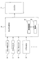
- FIG. 2 is a block diagram schematically showing functions of the engine ECU.
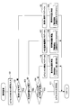
- FIG. 3 is a flowchart showing a flow of processing of the abnormality diagnosis routine.
- An air cleaner 13 is provided at the most upstream portion of an intake pipe 12 of an engine 11 (internal combustion engine) mounted on the vehicle, and an air flow meter 14 for detecting an intake air amount is provided downstream of the air cleaner 13. .
- a throttle valve 16 whose opening is adjusted by a motor 15 and a throttle opening sensor 17 for detecting the opening (throttle opening) of the throttle valve 16 are provided on the downstream side of the air flow meter 14.
- a surge tank 18 is provided on the downstream side of the throttle valve 16, and an intake pipe pressure sensor 19 for detecting the intake pipe pressure is provided in the surge tank 18.
- the surge tank 18 is provided with an intake manifold 20 for introducing air into each cylinder of the engine 11, and fuel is injected into the intake port at or near the intake port connected to the intake manifold 20 of each cylinder.
- a fuel injection valve 21 is attached.
- each cylinder of the engine 11 may be provided with a fuel injection valve that directly injects fuel into the cylinder.
- An ignition plug 22 is attached to the cylinder head of the engine 11 for each cylinder, and the air-fuel mixture in each cylinder is ignited by spark discharge of the ignition plug 22 of each cylinder.
- the exhaust pipe 23 of the engine 11 is provided with an exhaust gas sensor 24 (such as an air-fuel ratio sensor or an oxygen sensor) that detects the air-fuel ratio or rich / lean of the exhaust gas.
- an exhaust gas sensor 24 such as an air-fuel ratio sensor or an oxygen sensor
- a catalyst 25 such as a three-way catalyst for purifying gas is provided.
- a cooling water temperature sensor 26 for detecting the cooling water temperature and a knock sensor 27 for detecting knocking are attached to the cylinder block of the engine 11.
- a crank angle sensor 29 that outputs a pulse signal every time the crankshaft 28 rotates by a predetermined crank angle is attached to the outer peripheral side of the crankshaft 28, and the crank angle and the engine are determined based on the output signal of the crank angle sensor 29. The rotation speed is detected.
- the accelerator opening is detected by the accelerator sensor 31 (see FIG. 2)
- the brake operation or brake operation amount by the brake sensor
- the engine ECU 30 is mainly composed of a microcomputer, and executes various engine control programs stored in a built-in ROM (storage medium), thereby depending on the engine operating state, fuel injection amount, ignition Time, throttle opening (intake air amount), etc. are controlled.
- the engine ECU 30 transmits and receives information (for example, control signals and data signals) to and from the air conditioner ECU 33 that controls an air conditioner (air conditioner) mounted on the vehicle. .
- the engine ECU 30 also transmits / receives information to / from other ECUs (for example, an AT-ECU that controls the transmission, a brake ECU that controls the brake, etc.) mounted on the vehicle by CAN communication or the like.
- the air conditioner ECU 33 calculates a torque increase request value based on the operating state of the air conditioner and outputs a signal such as the torque increase request value.
- An output signal (such as a torque increase request value) of the air conditioner ECU 33 is input to the engine ECU 30.
- the air conditioner ECU 33 corresponds to the first arithmetic unit
- the engine ECU 30 corresponds to the second arithmetic unit.
- the engine ECU 30 calculates a required torque based on the output signals of sensors such as the crank angle sensor 29, the accelerator sensor 31, and the brake switch 32, the output signals of other ECUs such as the air conditioner ECU 33, and the like. Further, based on the required torque, engine control parameters (target throttle opening, fuel injection amount, ignition timing, etc.) are calculated to control the engine 11 (throttle valve 16, fuel injection valve 21, spark plug 22, etc.). To do.
- the engine ECU 30 is provided with an abnormality diagnosis unit 34 that performs abnormality diagnosis of the air conditioner ECU 33, and a monitoring IC 35 (monitoring unit) that monitors the abnormality diagnosis unit 34 is a circuit different from the abnormality diagnosis unit 34. Is provided.
- the abnormality diagnosis unit 34 performs abnormality diagnosis of the air conditioner ECU 33 by determining whether or not the output signal of the air conditioner ECU 33 is normal using a predetermined determination reference value. At that time, the monitoring IC 35 determines whether or not the determination reference value used in the abnormality diagnosis of the air conditioner ECU 33 is normal. Further, the abnormality diagnosis unit 34 determines whether or not the monitoring IC 35 is normal.
- the monitoring IC 35 determines that the determination reference value is abnormal, if the abnormality diagnosis of the air conditioner ECU 33 is performed using the abnormal determination reference value, there is a high possibility that the presence or absence of the abnormality of the air conditioner ECU 33 is erroneously determined. Become. Therefore, when the determination reference value is determined to be abnormal by the monitoring IC 35, the engine ECU 30 prohibits the abnormality diagnosis of the air conditioner ECU 33 and performs a predetermined abnormality treatment.
- the abnormality diagnosing unit 34 determines that the monitoring IC 35 is abnormal, the monitoring IC 35 may erroneously determine that the determination reference value is normal although the determination reference value is abnormal. In this case, if the abnormality diagnosis of the air conditioner ECU 33 is performed, there is a high possibility that the presence or absence of the abnormality of the air conditioner ECU 33 is erroneously determined. Therefore, when the abnormality diagnosis unit 34 determines that the monitoring IC 35 is abnormal, the engine ECU 30 prohibits the abnormality diagnosis of the air conditioner ECU 33 and performs a predetermined abnormality treatment.
- the abnormality diagnosis unit 34 compares the output signal of the air conditioner ECU 33 with the determination reference value to determine whether the output signal of the air conditioner ECU 33 is normal.
- the determination reference value for example, an upper limit determination value, a lower limit determination value, a change amount determination value of the output signal of the air conditioner ECU 33, a calculated value simulating the output signal of the air conditioner ECU 33 (the same as the air conditioner ECU 33 in the abnormality diagnosis unit 34) At least one of the values obtained by the calculation).
- the air conditioner ECU 33 determines to be normal.
- the air conditioner ECU 33 determines that the output signal is abnormal and performs a predetermined abnormality process.
- the abnormality diagnosis of the air conditioner ECU 33 described above is executed by the engine ECU 30 according to the abnormality diagnosis routine of FIG. The processing contents of this routine will be described below.
- the abnormality diagnosis routine shown in FIG. 3 is repeatedly executed at a predetermined cycle during the power-on period of the engine ECU 30.
- step 101 an output signal of the air conditioner ECU 33 is input.
- step 102 determine whether or not the monitoring IC 35 is normal.
- the abnormality diagnosis unit 34 outputs test data to the monitoring IC 35, and the monitoring IC 35 outputs a calculation result for the test data to the abnormality diagnosis unit 34.
- the abnormality diagnosis unit 34 checks the calculation result of the monitoring IC 35 with respect to the test data, and determines whether the monitoring IC 35 is abnormal.
- step 102 If it is determined in step 102 that the monitoring IC 35 is abnormal, if the abnormality diagnosis of the air conditioner ECU 33 is performed, it is determined that the possibility of erroneous determination of the presence or absence of the abnormality of the air conditioner ECU 33 is increased. Is prohibited.
- step 105 the abnormality flag of the monitoring IC 35 is set to ON, and the abnormality information (abnormality code, etc.) is stored in a rewritable nonvolatile memory (not shown) such as a backup RAM (not shown) of the engine ECU 30. It is stored in a rewritable memory that holds stored data even when the power is off.
- a rewritable nonvolatile memory not shown
- a backup RAM not shown
- step 106 an abnormality treatment is performed and this routine is terminated.
- a measure for notifying the driver of the abnormality is performed. Specifically, a warning lamp (not shown) provided on the instrument panel of the driver's seat is turned on or blinked, or a warning is displayed on a warning display section (not shown) of the instrument panel. Furthermore, as a measure at the time of abnormality, a measure to shift to a retreat travel mode (for example, a mode in which the vehicle speed or engine output is limited) or a measure to reset (restart) the engine ECU 30 is performed.
- a measure to shift to a retreat travel mode for example, a mode in which the vehicle speed or engine output is limited
- a measure to reset (restart) the engine ECU 30 is performed.
- step 102 determines whether or not the monitoring IC 35 is normal. If it is determined in step 102 that the monitoring IC 35 is normal, the process proceeds to step 103 to determine whether or not the determination reference value used in the abnormality diagnosis of the air conditioner ECU 33 is normal.
- the ROM or RAM check of the abnormality diagnosis unit 34 is performed by the monitoring IC 35 to store the ROM or RAM. By determining whether or not the data is normal, it is determined whether or not the determination reference value is normal.
- the monitoring IC 35 when calculating the determination reference value by calculating in the abnormality diagnosis unit 34, the monitoring IC 35 performs a FLOW check or the like of the abnormality diagnosis unit 34 to check whether the calculation function of the abnormality diagnosis unit 34 is operating normally. By determining whether or not, it is determined whether or not the determination reference value is normal.
- step 103 If it is determined in step 103 that the determination reference value is abnormal, it is determined that if the abnormality diagnosis of the air conditioner ECU 33 is performed, the possibility of misjudgment of the presence or absence of the abnormality of the air conditioner ECU 33 is increased. Prohibit diagnosis.
- step 107 the abnormality flag of the determination reference value is set to ON, and the abnormality information (abnormal code or the like) is stored in a rewritable nonvolatile memory such as a backup RAM of the engine ECU 30.
- Step 108 an abnormality treatment is performed and this routine is terminated.
- an abnormal measure a measure for notifying the driver of the abnormality is performed. Further, a process for shifting to the retreat traveling mode or a process for resetting the engine ECU 30 is performed.
- step 102 if the monitoring IC 35 is determined to be normal in step 102 and the determination reference value is determined to be normal in step 103, abnormality diagnosis of the air conditioner ECU 33 is permitted.
- step 104 the output signal of the air conditioner ECU 33 is compared with the determination reference value to determine whether the output signal of the air conditioner ECU 33 is normal.
- the output signal of the air conditioner ECU 33 is within a normal range (not less than the lower limit determination value and not more than the upper limit determination value). It is determined whether or not the output signal of the air conditioner ECU 33 is normal.
- the change amount determination value of the output signal of the air conditioner ECU 33 is used as the determination reference value, it is determined whether or not the change amount of the output signal of the air conditioner ECU 33 is equal to or less than the change amount determination value. It is determined whether the output signal of the ECU 33 is normal.
- the output signal and the calculation value of the air conditioner ECU 33 are used. It is determined whether or not the output signal of the air conditioner ECU 33 is normal.
- the method for determining whether or not the output signal of the ECU 33 is normal is not limited to the method described above, and may be changed as appropriate. For example, (1) the output signal of the air conditioner ECU 33 is within the normal range, (2) the change amount of the output signal of the ECU air conditioner ECU 33 is equal to or less than the change amount determination value, (3) the output signal and the calculated value of the air conditioner ECU 33 When two or three of the deviations are less than or equal to a predetermined value, the output signal of the ECU 33 may be determined to be normal.
- step 104 If it is determined in step 104 that the output signal of the air conditioner ECU 33 is abnormal, the process proceeds to step 109, where it is determined that the air conditioner ECU 33 is abnormal, and the abnormality flag of the air conditioner ECU 33 is set to ON. Code or the like) is stored in a rewritable nonvolatile memory such as a backup RAM of the engine ECU 30.
- step 110 an abnormality treatment is performed and this routine is terminated.
- this abnormal measure a measure for notifying the driver of the abnormality is performed. Further, a process of replacing the output signal of the air conditioner ECU 33 with a fail safe value is performed.
- step 104 determines whether the output signal of the air conditioner ECU 33 is normal. If it is determined in step 104 that the output signal of the air conditioner ECU 33 is normal, the process proceeds to step 111, where it is determined that the air conditioner ECU 33 is normal, and this routine is terminated.
- the abnormality diagnosis unit 34 is provided in the engine ECU 30, and the abnormality diagnosis unit 34 compares the output signal of the air conditioner ECU 33 with the determination reference value to determine whether the output signal of the air conditioner ECU 33 is normal. By determining whether or not, the abnormality diagnosis of the air conditioner ECU 33 is performed. Further, the engine ECU 30 is provided with a monitoring IC 35 by a circuit different from the abnormality diagnosis unit 34, and the monitoring IC 35 determines whether or not the determination reference value used for abnormality diagnosis of the air conditioner ECU 33 is normal. Thus, the monitoring IC 35 can monitor the determination reference value to determine whether or not the determination reference value is normal. Therefore, even if the determination reference value becomes an abnormal value, Abnormalities can be detected. Thereby, it is possible to prevent erroneous determination of abnormality diagnosis due to abnormality of the determination reference value, and the abnormality diagnosis accuracy of the air conditioner ECU 33 can be improved.
- the abnormality diagnosis unit 34 determines whether or not the monitoring IC 35 is normal. In this way, the abnormality diagnosing unit 34 can monitor the monitoring IC 35 to ensure the operation of the monitoring IC 35.
- the monitoring IC 35 determines that the determination reference value is abnormal, if the abnormality diagnosis of the air conditioner ECU 33 is performed using the abnormal determination reference value, there is a high possibility that the presence or absence of the abnormality of the air conditioner ECU 33 is erroneously determined. Become. Therefore, in this embodiment, when the monitoring IC 35 determines that the determination reference value is abnormal, abnormality diagnosis of the air conditioner ECU 33 is prohibited. By doing so, it is possible to prevent erroneous determination of abnormality diagnosis due to abnormality of the determination reference value.
- the abnormality diagnosis unit 34 determines that the monitoring IC 35 is abnormal, the monitoring IC 35 may erroneously determine that the determination reference value is normal although the determination reference value is abnormal. In this case, if the abnormality diagnosis of the air conditioner ECU 33 is performed, there is a high possibility that the presence or absence of the abnormality of the air conditioner ECU 33 is erroneously determined. Thus, in this embodiment, when the abnormality diagnosis unit 34 determines that the monitoring IC 35 is abnormal, abnormality diagnosis of the air conditioner ECU 33 is prohibited. In this way, it is possible to prevent erroneous determination of abnormality diagnosis due to abnormality of the monitoring IC 35.
- a measure for an abnormality a measure for shifting to the retreat travel mode or a measure for resetting the engine ECU 30 is performed.
- the vehicle can travel safely to a maintenance shop or the like. If the engine ECU 30 is reset, there is a possibility that the abnormality of the judgment reference value and the abnormality of the monitoring IC 35 can be solved and the normal operation can be restored.
- the determination reference value used for the abnormality diagnosis of the air conditioner ECU 33 includes an upper limit determination value, a lower limit determination value, a change amount determination value of the output signal of the air conditioner ECU 33, and a calculated value simulating the output signal of the air conditioner ECU 33. At least one of these is used. In this way, it is possible to easily determine whether or not the output signal of the air conditioner ECU 33 is normal by comparing the output signal of the air conditioner ECU 33 with the determination reference value.
- the air conditioner ECU 33 determines that the abnormality is present, and performs an abnormality treatment. In this way, when the output signal of the air conditioner ECU 33 is determined to be abnormal, it is possible to perform an appropriate abnormality measure.
- a measure for an abnormality a measure is performed to replace the output signal of the air conditioner ECU 33 with a fail-safe value. Thereby, the output signal of the air conditioner ECU 33 can be replaced with a fail-safe value, and the control of the vehicle can be continued.
- the monitoring IC 35 is provided in the engine ECU 30, but the present invention is not limited to this.
- the monitoring IC 35 may be provided outside the engine ECU 30.
- the present disclosure is applied to a system in which the abnormality diagnosis unit of the engine ECU determines whether the output signal of the air conditioner ECU is normal.
- the present invention is not limited to this.
- a system for determining whether an output signal of a vehicle-mounted ECU (for example, an AT-ECU or a brake ECU) other than an air conditioner ECU is normal.
- the present disclosure may be applied.
- the present disclosure may be applied to a system in which an abnormality diagnosis unit of a vehicle-mounted ECU other than the engine ECU determines whether output signals of other vehicle-mounted ECUs are normal.
Landscapes
- Engineering & Computer Science (AREA)
- General Engineering & Computer Science (AREA)
- Chemical & Material Sciences (AREA)
- Combustion & Propulsion (AREA)
- Mechanical Engineering (AREA)
- Computer Hardware Design (AREA)
- Physics & Mathematics (AREA)
- General Physics & Mathematics (AREA)
- Microelectronics & Electronic Packaging (AREA)
- Combined Controls Of Internal Combustion Engines (AREA)
Abstract
エンジンECU(30)に、エアコンECU(33)の異常診断を行う異常診断部(34)と、この異常診断部(34)を監視する監視IC(35)を設ける。異常診断部(34)は、エアコンECU(33)の出力信号が正常であるか否かを所定の判定基準値を用いて判定することでエアコンECU(33)の異常診断を行う。その際、監視IC(35)は、エアコンECU(33)の異常診断で用いる判定基準値が正常であるか否かを判定し、異常診断部(34)は、監視IC(35)が正常であるか否かを判定する。そして、監視IC(35)により判定基準値が異常と判定された場合や、異常診断部(34)により監視IC(35)が異常と判定された場合には、エアコンECU(33)の異常診断を禁止して、所定の異常時処置を実施する。
Description
本出願は、2015年2月11日に出願された日本特許出願番号2015-24842号に基づくもので、ここにその記載内容を援用する。
本開示は、複数の演算装置を備えた車両の制御装置に関する。
近年の電子制御化された車両においては、制御システムの信頼性や安全性を確保する技術として、例えば、特許文献1(特開平6-50851号公報)に記載されたものがある。このものは、車載データ記憶装置と故障診断装置本体とを備え、車載データ記憶装置は、車載電子制御装置の入出力データを取り込んで記憶し、故障診断装置本体は、車載データ記憶装置に記憶されたデータを取り込み、それを予め記憶された所定の判定基準値と比較して故障の有無を診断するようにしている。
車両の制御システムにおいては、エンジンを制御する演算装置(電子制御ユニット)、変速機を制御する演算装置、エアコン(空調装置)を制御する演算装置等の複数の演算装置を備えたものがある。このように複数の演算装置を備えた車両の制御システムでは、各演算装置に、それぞれ演算装置の異常診断回路を設けると、近年の重要な技術的課題である低コスト化の要求を満たすことができなくなる可能性がある。
本出願人は、第1の演算装置の出力信号を第2の演算装置に入力する車両の制御システムにおいて、第2の演算装置(入力側の演算装置)で、第1の演算装置の出力信号が正常であるか否かを判定することで第1の演算装置(出力側の演算装置)の異常診断を行うシステムを研究しているが、その研究過程で次のような新たな課題が判明した。
何らかの原因(例えばROMのデータ化け等)により、第1の演算装置の異常診断で用いる判定基準値が異常値になる可能性もあり、その異常な判定基準値を用いて第1の演算装置の異常診断を行うと、第1の演算装置の異常の有無を誤判定する可能性が高くなる。しかし、判定基準値を監視する機能が無いと、判定基準値の異常を検出できないため、判定基準値の異常による異常診断の誤判定を防止することができず、第1の演算装置の異常診断精度が低下する可能性がある。上記特許文献1においても、判定基準値を監視する技術は開示されていない。
本開示は、第2の演算装置で第1の演算装置の異常診断を行うシステムにおいて、第1の演算装置の異常診断精度を向上させることができる車両の制御装置を提供することを目的とする。
本開示の一態様によれば、第1の演算装置の出力信号を第2の演算装置に入力する車両の制御装置において、第2の演算装置に設けられて第1の演算装置の出力信号が正常であるか否かを所定の判定基準値を用いて判定することで第1の演算装置の異常診断を行う異常診断部と、この異常診断部とは別に設けられて判定基準値が正常であるか否かを判定する監視部とを備える。
この構成では、監視部で判定基準値を監視して判定基準値が正常であるか否かを判定することができるため、もし、判定基準値が異常値になった場合でも、その判定基準値の異常を検出することができる。これにより、判定基準値の異常による異常診断の誤判定を防止することが可能となり、第1の演算装置の異常診断精度を向上させることができる。
本開示についての上記目的およびその他の目的、特徴や利点は、添付の図面を参照しながら下記の詳細な記述により、より明確になる。
図1は本開示の一実施例におけるエンジン制御システムの概略構成を示す図である。
図2はエンジンECUの機能を概略的に示すブロック図である。
図3は異常診断ルーチンの処理の流れを示すフローチャートである。
以下、本開示を実施するための形態を具体化した一実施例を説明する。
図1に基づいてエンジン制御システムの概略構成を説明する。
車両に搭載されたエンジン11(内燃機関)の吸気管12の最上流部には、エアクリーナ13が設けられ、このエアクリーナ13の下流側に、吸入空気量を検出するエアフローメータ14が設けられている。このエアフローメータ14の下流側には、モータ15によって開度調節されるスロットルバルブ16と、このスロットルバルブ16の開度(スロットル開度)を検出するスロットル開度センサ17とが設けられている。
更に、スロットルバルブ16の下流側には、サージタンク18が設けられ、このサージタンク18に、吸気管圧力を検出する吸気管圧力センサ19が設けられている。また、サージタンク18には、エンジン11の各気筒に空気を導入する吸気マニホールド20が設けられ、各気筒の吸気マニホールド20に接続された吸気ポート又はその近傍に、それぞれ吸気ポートに燃料を噴射する燃料噴射弁21が取り付けられている。或は、エンジン11の各気筒に、それぞれ筒内に燃料を直接噴射する燃料噴射弁が取り付けられているようにしても良い。また、エンジン11のシリンダヘッドには、各気筒毎に点火プラグ22が取り付けられ、各気筒の点火プラグ22の火花放電によって各気筒内の混合気に着火される。
一方、エンジン11の排気管23には、排出ガスの空燃比又はリッチ/リーン等を検出する排出ガスセンサ24(空燃比センサ又は酸素センサ等)が設けられ、この排出ガスセンサ24の下流側に、排出ガスを浄化する三元触媒等の触媒25が設けられている。
また、エンジン11のシリンダブロックには、冷却水温を検出する冷却水温センサ26や、ノッキングを検出するノックセンサ27が取り付けられている。また、クランク軸28の外周側には、クランク軸28が所定クランク角回転する毎にパルス信号を出力するクランク角センサ29が取り付けられ、このクランク角センサ29の出力信号に基づいてクランク角やエンジン回転速度が検出される。更に、アクセルセンサ31(図2参照)によってアクセル開度(アクセルペダルの操作量)が検出され、ブレーキスイッチ32(図2参照)によってブレーキ操作(又はブレーキセンサによってブレーキ操作量)が検出される。
これら各種センサやスイッチの出力は、エンジンECU30に入力される。このエンジンECU30は、マイクロコンピュータを主体として構成され、内蔵されたROM(記憶媒体)に記憶された各種のエンジン制御用のプログラムを実行することで、エンジン運転状態に応じて、燃料噴射量、点火時期、スロットル開度(吸入空気量)等を制御する。
図2に示すように、エンジンECU30は、車両に搭載されたエアコン(空調装置)を制御するエアコンECU33との間で、CAN通信等により情報(例えば制御信号やデータ信号等)を相互に送受信する。また、エンジンECU30は、車両に搭載された他のECU(例えば、変速機を制御するAT-ECU、ブレーキを制御するブレーキECU等)との間でも、CAN通信等により情報を相互に送受信する。
エアコンECU33は、エアコンの運転状態等に基づいてトルクアップ要求値等を演算し、そのトルクアップ要求値等の信号を出力する。このエアコンECU33の出力信号(トルクアップ要求値等)は、エンジンECU30に入力される。本実施例では、エアコンECU33が第1の演算装置に相当し、エンジンECU30が第2の演算装置に相当する。
エンジンECU30は、クランク角センサ29、アクセルセンサ31、ブレーキスイッチ32等のセンサやスイッチの出力信号や、エアコンECU33等の他のECUの出力信号等に基づいて、要求トルクを演算する。更に、この要求トルクに基づいて、エンジン制御パラメータ(目標スロットル開度、燃料噴射量、点火時期等)を演算して、エンジン11(スロットルバルブ16、燃料噴射弁21、点火プラグ22等)を制御する。
また、エンジンECU30には、エアコンECU33の異常診断を行う異常診断部34が設けられていると共に、この異常診断部34を監視する監視IC35(監視部)が異常診断部34とは別の回路で設けられている。
異常診断部34は、エアコンECU33の出力信号が正常であるか否かを所定の判定基準値を用いて判定することでエアコンECU33の異常診断を行う。その際、監視IC35は、エアコンECU33の異常診断で用いる判定基準値が正常であるか否かを判定する。また、異常診断部34は、監視IC35が正常であるか否かを判定する。
そして、監視IC35により判定基準値が異常と判定された場合には、その異常な判定基準値を用いてエアコンECU33の異常診断を行うと、エアコンECU33の異常の有無を誤判定する可能性が高くなる。そこで、エンジンECU30は、監視IC35により判定基準値が異常と判定された場合には、エアコンECU33の異常診断を禁止して、所定の異常時処置を実施する。
また、異常診断部34により監視IC35が異常と判定された場合には、判定基準値が異常であるにも拘らず監視IC35で判定基準値が正常と誤判定する可能性があり、このような場合に、エアコンECU33の異常診断を行うと、エアコンECU33の異常の有無を誤判定する可能性が高くなる。そこで、エンジンECU30は、異常診断部34により監視IC35が異常と判定された場合には、エアコンECU33の異常診断を禁止して、所定の異常時処置を実施する。
一方、監視IC35により判定基準値が正常と判定され、且つ、異常診断部34により監視IC35が正常と判定された場合には、エアコンECU33の異常診断を許可する。この場合、異常診断部34で、エアコンECU33の出力信号を判定基準値と比較してエアコンECU33の出力信号が正常であるか否かを判定する。この際、判定基準値として、例えば、エアコンECU33の出力信号の上限判定値、下限判定値、変化量判定値、エアコンECU33の出力信号を模擬した演算値(異常診断部34でエアコンECU33と同様の演算を行って求めた値)のうちの少なくとも一つを用いる。
その結果、エアコンECU33の出力信号が正常と判定された場合には、エアコンECU33が正常と判定する。これに対して、エアコンECU33の出力信号が異常と判定された場合には、エアコンECU33が異常と判定して、所定の異常時処置を実施する。
以上説明したエアコンECU33の異常診断は、エンジンECU30によって図3の異常診断ルーチンに従って実行される。以下、このルーチンの処理内容を説明する。
図3に示す異常診断ルーチンは、エンジンECU30の電源オン期間中に所定周期で繰り返し実行される。ステップ101で、エアコンECU33の出力信号を入力する。
この後、ステップ102に進み、監視IC35が正常であるか否かを判定する。この場合、例えば、異常診断部34が監視IC35にテストデータ出力し、監視IC35がテストデータに対する演算結果を異常診断部34に出力する。異常診断部34は、テストデータに対する監視IC35の演算結果をチェックして、監視IC35の異常の有無を判定する。
このステップ102で、監視IC35が異常と判定された場合には、エアコンECU33の異常診断を行うと、エアコンECU33の異常の有無を誤判定する可能性が高くなると判断して、エアコンECU33の異常診断を禁止する。
この場合、ステップ105に進み、監視IC35の異常フラグをONにセットし、その異常情報(異常コード等)をエンジンECU30のバックアップRAM(図示せず)等の書き換え可能な不揮発性メモリ(エンジンECU30の電源オフ中でも記憶データを保持する書き換え可能なメモリ)に記憶する。
この後、ステップ106に進み、異常時処置を実施して、本ルーチンを終了する。この異常時処置としては、運転者に異常を報知する処置を実施する。具体的には、運転席のインストルメントパネルに設けられた警告ランプ(図示せず)を点灯又は点滅したり、或は、インストルメントパネルの警告表示部(図示せず)に警告表示する。更に、異常時処置として、退避走行モード(例えば車速やエンジン出力等を制限したモード)へ移行する処置又はエンジンECU30をリセット(再起動)する処置を実施する。
一方、上記ステップ102で、監視IC35が正常と判定された場合には、ステップ103に進み、エアコンECU33の異常診断で用いる判定基準値が正常であるか否かを判定する。
この際、例えば、異常診断部34のROMやRAMに判定基準値を記憶している場合には、監視IC35で、異常診断部34のROMチェックやRAMチェック等を行って、ROMやRAMの記憶データが正常であるか否かを判定することで、判定基準値が正常であるか否かを判定する。
或は、異常診断部34で演算して判定基準値を求める場合には、監視IC35で、異常診断部34のFLOWチェック等を行って、異常診断部34の演算機能が正常に動作しているか否かを判定することで、判定基準値が正常であるか否かを判定する。
このステップ103で、判定基準値が異常と判定された場合には、エアコンECU33の異常診断を行うと、エアコンECU33の異常の有無を誤判定する可能性が高くなると判断して、エアコンECU33の異常診断を禁止する。
この場合、ステップ107に進み、判定基準値の異常フラグをONにセットし、その異常情報(異常コード等)をエンジンECU30のバックアップRAM等の書き換え可能な不揮発性メモリに記憶する。
この後、ステップ108に進み、異常時処置を実施して、本ルーチンを終了する。この異常時処置としては、運転者に異常を報知する処置を実施する。更に、退避走行モードへ移行する処置又はエンジンECU30をリセットする処置を実施する。
一方、上記ステップ102で監視IC35が正常と判定され、且つ、上記ステップ103で判定基準値が正常と判定された場合には、エアコンECU33の異常診断を許可する。
この場合、ステップ104に進み、エアコンECU33の出力信号を判定基準値と比較してエアコンECU33の出力信号が正常であるか否かを判定する。
この際、例えば、判定基準値として、エアコンECU33の出力信号の上限判定値及び下限判定値を用いる場合には、エアコンECU33の出力信号が正常範囲内(下限判定値以上で且つ上限判定値以下の範囲内)であるか否かを判定することで、エアコンECU33の出力信号が正常であるか否かを判定する。
或は、判定基準値として、エアコンECU33の出力信号の変化量判定値を用いる場合には、エアコンECU33の出力信号の変化量が変化量判定値以下であるか否かを判定することで、エアコンECU33の出力信号が正常であるか否かを判定する。
また、判定基準値として、エアコンECU33の出力信号を模擬した演算値(異常診断部34でエアコンECU33と同様の演算を行って求めた値)を用いる場合には、エアコンECU33の出力信号と演算値との偏差が所定値以下であるか否かを判定することで、エアコンECU33の出力信号が正常であるか否かを判定する。
尚、ECU33の出力信号が正常であるか否かを判定する方法は、上述した方法に限定されず、適宜変更しても良い。例えば、(1) エアコンECU33の出力信号が正常範囲内であること、(2) エアコンECU33の出力信号の変化量が変化量判定値以下であること、(3) エアコンECU33の出力信号と演算値との偏差が所定値以下であること、のうちの二つ又は三つが成立したときに、ECU33の出力信号が正常と判定するようにしても良い。
このステップ104で、エアコンECU33の出力信号が異常と判定された場合には、ステップ109に進み、エアコンECU33の異常と判定して、エアコンECU33の異常フラグをONにセットし、その異常情報(異常コード等)をエンジンECU30のバックアップRAM等の書き換え可能な不揮発性メモリに記憶する。
この後、ステップ110に進み、異常時処置を実施して、本ルーチンを終了する。この異常時処置としては、運転者に異常を報知する処置を実施する。更に、エアコンECU33の出力信号をフェイルセーフ値に置き換える処置を実施する。
これに対して、上記ステップ104で、エアコンECU33の出力信号が正常と判定された場合には、ステップ111に進み、エアコンECU33の正常と判定して、本ルーチンを終了する。
以上説明した本実施例では、エンジンECU30に、異常診断部34を設け、この異常診断部34で、エアコンECU33の出力信号を判定基準値と比較してエアコンECU33の出力信号が正常であるか否かを判定することでエアコンECU33の異常診断を行う。更に、エンジンECU30に、異常診断部34とは別の回路で監視IC35を設け、この監視IC35で、エアコンECU33の異常診断で用いる判定基準値が正常であるか否かを判定する。これにより、監視IC35で判定基準値を監視して判定基準値が正常であるか否かを判定することができるため、もし、判定基準値が異常値になった場合でも、その判定基準値の異常を検出することができる。これにより、判定基準値の異常による異常診断の誤判定を防止することが可能となり、エアコンECU33の異常診断精度を向上させることができる。
更に、本実施例では、異常診断部34で、監視IC35が正常であるか否かを判定するようにしている。このようにすれば、異常診断部34で監視IC35を監視して、監視IC35の動作を保証することができる。
また、監視IC35により判定基準値が異常と判定された場合には、その異常な判定基準値を用いてエアコンECU33の異常診断を行うと、エアコンECU33の異常の有無を誤判定する可能性が高くなる。そこで、本実施例では、監視IC35により判定基準値が異常と判定された場合には、エアコンECU33の異常診断を禁止するようにしている。このようにすれば、判定基準値の異常による異常診断の誤判定を未然に防止することができる。
一方、異常診断部34により監視IC35が異常と判定された場合には、判定基準値が異常であるにも拘らず監視IC35で判定基準値が正常と誤判定する可能性があり、このような場合に、エアコンECU33の異常診断を行うと、エアコンECU33の異常の有無を誤判定する可能性が高くなる。そこで、本実施例では、異常診断部34により監視IC35が異常と判定された場合には、エアコンECU33の異常診断を禁止するようにしている。このようにすれば、監視IC35の異常による異常診断の誤判定を未然に防止することができる。
また、本実施例では、監視IC35により判定基準値が異常と判定された場合や、異常診断部34により監視IC35が異常と判定された場合には、異常時処置を実施するようにしている。これにより、判定基準値が異常と判定された場合や監視IC35が異常と判定された場合に、適切な異常時処置を実施することができる。
その際、本実施例では、異常時処置として、退避走行モードへ移行する処置又はエンジンECU30をリセットする処置を実施するようにしている。退避走行モードへ移行すれば、車両を整備工場等まで安全に走行させることができる。エンジンECU30をリセットすれば、判定基準値の異常や監視IC35の異常を解消して正常復帰できる可能性がある。
また、本実施例では、エアコンECU33の異常診断で用いる判定基準値として、エアコンECU33の出力信号の上限判定値、下限判定値、変化量判定値、エアコンECU33の出力信号を模擬した演算値のうちの少なくとも一つを用いるようにしている。このようにすれば、エアコンECU33の出力信号を判定基準値と比較して、エアコンECU33の出力信号が正常であるか否かを容易に判定することができる。
更に、本実施例では、異常診断部34によりエアコンECU33の出力信号が異常と判定された場合には、エアコンECU33が異常と判定して、異常時処置を実施するようにしている。このようにすれば、エアコンECU33の出力信号が異常と判定された場合に適切な異常時処置を実施することができる。
その際、本実施例では、異常時処置として、エアコンECU33の出力信号をフェイルセーフ値に置き換える処置を実施するようにしている。これにより、エアコンECU33の出力信号をフェイルセーフ値に置き換えて、車両の制御を継続することができる。
また、本実施例では、判定基準値が異常と判定された場合や監視IC35が異常と判定された場合の異常時処置及びエアコンECU33の出力信号が異常と判定された場合の異常時処置として、運転者に異常を報知する処置を実施するようにしている。これにより、運転者に異常を速やかに報知して、整備工場等での点検・修理を促すことができる。
尚、上記実施例では、エンジンECU30内に監視IC35を設ける構成としたが、これに限定されず、例えば、エンジンECU30の外部に監視IC35を設ける構成としても良い。
また、上記実施例では、エンジンECUの異常診断部で、エアコンECUの出力信号が正常であるか否かを判定するシステムに本開示を適用した。しかし、これに限定されず、例えば、エンジンECUの異常診断部で、エアコンECU以外の車両搭載ECU(例えばAT-ECUやブレーキECU等)の出力信号が正常であるか否かを判定するシステムに本開示を適用しても良い。或は、エンジンECU以外の車両搭載ECUの異常診断部で、その他の車両搭載ECUの出力信号が正常であるか否かを判定するシステムに本開示を適用しても良い。
本開示は、実施例に準拠して記述されたが、本開示は当該実施例や構造に限定されるものではないと理解される。本開示は、様々な変形例や均等範囲内の変形をも包含する。加えて、様々な組み合わせや形態、さらには、それらに一要素のみ、それ以上、あるいはそれ以下、を含む他の組み合わせや形態をも、本開示の範疇や思想範囲に入るものである。
Claims (11)
- 第1の演算装置(33)の出力信号を第2の演算装置(30)に入力する車両の制御装置において、
前記第2の演算装置(30)に設けられて前記第1の演算装置(33)の出力信号が正常であるか否かを所定の判定基準値を用いて判定することで前記第1の演算装置(33)の異常診断を行う異常診断部(34)と、
前記異常診断部(34)とは別に設けられて前記判定基準値が正常であるか否かを判定する監視部(35)と
を備えている車両の制御装置。 - 前記第2の演算装置(30)は、前記監視部(35)により前記判定基準値が異常と判定された場合に、前記第1の演算装置(33)の異常診断を禁止する請求項1に記載の車両の制御装置。
- 前記第2の演算装置(30)は、前記監視部(35)により前記判定基準値が異常と判定された場合に、所定の異常時処置を実施する請求項1又は2に記載の車両の制御装置。
- 前記異常診断部(34)は、前記監視部(35)が正常であるか否かを判定する機能を有する請求項1乃至3のいずれかに記載の車両の制御装置。
- 前記第2の演算装置(30)は、前記異常診断部(34)により前記監視部(35)が異常と判定された場合に、前記第1の演算装置(33)の異常診断を禁止する請求項4に記載の車両の制御装置。
- 前記第2の演算装置(30)は、前記異常診断部(34)により前記監視部(35)が異常と判定された場合に、所定の異常時処置を実施する請求項4又は5に記載の車両の制御装置。
- 前記第2の演算装置(30)は、前記異常時処置として、該第2の演算装置(30)をリセットする処置又は退避走行モードへ移行する処置を実施する請求項3又は6に記載の車両の制御装置。
- 前記異常診断部(34)は、前記判定基準値として、前記第1の演算装置(33)の出力信号の上限判定値、下限判定値、変化量判定値、該出力信号を模擬した演算値のうちの少なくとも一つを用いる請求項1乃至7のいずれかに記載の車両の制御装置。
- 前記第2の演算装置(30)は、前記異常診断部(34)により前記第1の演算装置(33)の出力信号が異常と判定された場合に、前記第1の演算装置(33)が異常と判定して所定の異常時処置を実施する請求項1乃至8のいずれかに記載の車両の制御装置。
- 前記第2の演算装置(30)は、前記異常時処置として、前記第1の演算装置(33)の出力信号をフェイルセーフ値に置き換える処置を実施する請求項9に記載の車両の制御装置。
- 前記第2の演算装置(30)は、前記異常時処置として、運転者に異常を報知する処置を実施する請求項3、6、9のいずれかに記載の車両の制御装置。
Priority Applications (1)
| Application Number | Priority Date | Filing Date | Title |
|---|---|---|---|
| US15/525,628 US10378473B2 (en) | 2015-02-11 | 2016-02-02 | Vehicle control device |
Applications Claiming Priority (2)
| Application Number | Priority Date | Filing Date | Title |
|---|---|---|---|
| JP2015-024842 | 2015-02-11 | ||
| JP2015024842A JP6358120B2 (ja) | 2015-02-11 | 2015-02-11 | 車両の制御装置 |
Publications (1)
| Publication Number | Publication Date |
|---|---|
| WO2016129243A1 true WO2016129243A1 (ja) | 2016-08-18 |
Family
ID=56614570
Family Applications (1)
| Application Number | Title | Priority Date | Filing Date |
|---|---|---|---|
| PCT/JP2016/000525 Ceased WO2016129243A1 (ja) | 2015-02-11 | 2016-02-02 | 車両の制御装置 |
Country Status (3)
| Country | Link |
|---|---|
| US (1) | US10378473B2 (ja) |
| JP (1) | JP6358120B2 (ja) |
| WO (1) | WO2016129243A1 (ja) |
Families Citing this family (3)
| Publication number | Priority date | Publication date | Assignee | Title |
|---|---|---|---|---|
| KR101846722B1 (ko) * | 2016-10-20 | 2018-04-09 | 현대자동차주식회사 | 차량의 냉각시스템 및 그 제어방법 |
| JP6984512B2 (ja) * | 2018-03-22 | 2021-12-22 | 株式会社デンソー | 電子制御装置 |
| JP7747447B2 (ja) * | 2021-05-26 | 2025-10-01 | ナブテスコ株式会社 | 自動ドア装置及び自動ドア診断システム |
Citations (5)
| Publication number | Priority date | Publication date | Assignee | Title |
|---|---|---|---|---|
| JP2000274300A (ja) * | 1999-03-24 | 2000-10-03 | Denso Corp | 車両用電子制御装置 |
| JP2003254094A (ja) * | 2002-02-28 | 2003-09-10 | Denso Corp | 車両用電子制御装置 |
| JP2011032903A (ja) * | 2009-07-30 | 2011-02-17 | Denso Corp | 車両の制御装置 |
| JP2012096763A (ja) * | 2010-11-05 | 2012-05-24 | Hitachi Automotive Systems Ltd | 車両の故障診断制御装置及びその故障診断制御方法 |
| JP2013169917A (ja) * | 2012-02-22 | 2013-09-02 | Toyota Motor Corp | 車両および車両の制御方法 |
Family Cites Families (4)
| Publication number | Priority date | Publication date | Assignee | Title |
|---|---|---|---|---|
| JPH0650851A (ja) | 1991-12-26 | 1994-02-25 | Suzuki Motor Corp | 車両用故障診断方法及びその装置 |
| JPH05240118A (ja) * | 1992-03-02 | 1993-09-17 | Honda Motor Co Ltd | 内燃エンジンの蒸発燃料処理系の異常診断装置 |
| JP3204108B2 (ja) * | 1996-08-23 | 2001-09-04 | トヨタ自動車株式会社 | 空気温センサの異常検出装置 |
| JP2013092397A (ja) * | 2011-10-24 | 2013-05-16 | Denso Corp | 電池監視装置 |
-
2015
- 2015-02-11 JP JP2015024842A patent/JP6358120B2/ja active Active
-
2016
- 2016-02-02 WO PCT/JP2016/000525 patent/WO2016129243A1/ja not_active Ceased
- 2016-02-02 US US15/525,628 patent/US10378473B2/en active Active
Patent Citations (5)
| Publication number | Priority date | Publication date | Assignee | Title |
|---|---|---|---|---|
| JP2000274300A (ja) * | 1999-03-24 | 2000-10-03 | Denso Corp | 車両用電子制御装置 |
| JP2003254094A (ja) * | 2002-02-28 | 2003-09-10 | Denso Corp | 車両用電子制御装置 |
| JP2011032903A (ja) * | 2009-07-30 | 2011-02-17 | Denso Corp | 車両の制御装置 |
| JP2012096763A (ja) * | 2010-11-05 | 2012-05-24 | Hitachi Automotive Systems Ltd | 車両の故障診断制御装置及びその故障診断制御方法 |
| JP2013169917A (ja) * | 2012-02-22 | 2013-09-02 | Toyota Motor Corp | 車両および車両の制御方法 |
Also Published As
| Publication number | Publication date |
|---|---|
| US20170335785A1 (en) | 2017-11-23 |
| US10378473B2 (en) | 2019-08-13 |
| JP6358120B2 (ja) | 2018-07-18 |
| JP2016148562A (ja) | 2016-08-18 |
Similar Documents
| Publication | Publication Date | Title |
|---|---|---|
| JP4831015B2 (ja) | 内燃機関の異常診断装置 | |
| JP4924905B2 (ja) | 車両の制御装置 | |
| JP4618220B2 (ja) | ガスセンサの組み付け状態検出方法及びガスセンサの組み付け状態検出装置 | |
| JP4915526B2 (ja) | 内燃機関の空燃比制御装置 | |
| US8459005B2 (en) | Method and device for diagnosing a particle filter | |
| CN102884301B (zh) | 空气流量计的故障诊断装置 | |
| JP4873378B2 (ja) | 吸入空気量センサの異常診断装置 | |
| JP2010106785A (ja) | 排出ガス還流システムの異常診断装置 | |
| JP6358120B2 (ja) | 車両の制御装置 | |
| KR20150073238A (ko) | 차량의 전자제어장치 진단기의 시뮬레이션장치 | |
| US7131321B2 (en) | Throttle system abnormality determination apparatus | |
| JP4753085B2 (ja) | 内燃機関の制御装置 | |
| JP2009062998A (ja) | 車両制御システム | |
| WO2013065400A1 (ja) | ノックセンサの故障診断装置及び故障診断方法 | |
| JP2010127162A (ja) | スロットル制御システムのフェールセーフ装置 | |
| JP2007085176A (ja) | 気筒別燃料噴射弁故障診断 | |
| JP2010163932A (ja) | 内燃機関の触媒劣化診断装置 | |
| JP6446341B2 (ja) | 内燃機関の制御装置 | |
| JP5603825B2 (ja) | 空燃比センサの診断装置 | |
| JP2016223415A (ja) | 内燃機関の制御装置 | |
| JP4210940B2 (ja) | 吸気系センサの異常診断装置 | |
| JP3754212B2 (ja) | 内燃機関の警告灯故障診断装置、方法及び故障時制御方法 | |
| JP2010001872A (ja) | 内燃機関制御装置 | |
| JP5157924B2 (ja) | エンジンの診断装置 | |
| JPH11280515A (ja) | 車両制御装置 |
Legal Events
| Date | Code | Title | Description |
|---|---|---|---|
| 121 | Ep: the epo has been informed by wipo that ep was designated in this application |
Ref document number: 16748890 Country of ref document: EP Kind code of ref document: A1 |
|
| NENP | Non-entry into the national phase |
Ref country code: DE |
|
| 122 | Ep: pct application non-entry in european phase |
Ref document number: 16748890 Country of ref document: EP Kind code of ref document: A1 |