WO2016125289A1 - X線発生装置 - Google Patents
X線発生装置 Download PDFInfo
- Publication number
- WO2016125289A1 WO2016125289A1 PCT/JP2015/053256 JP2015053256W WO2016125289A1 WO 2016125289 A1 WO2016125289 A1 WO 2016125289A1 JP 2015053256 W JP2015053256 W JP 2015053256W WO 2016125289 A1 WO2016125289 A1 WO 2016125289A1
- Authority
- WO
- WIPO (PCT)
- Prior art keywords
- ray
- target
- electron beam
- absorption rate
- irradiation
- Prior art date
- Legal status (The legal status is an assumption and is not a legal conclusion. Google has not performed a legal analysis and makes no representation as to the accuracy of the status listed.)
- Ceased
Links
Images




Classifications
-
- H—ELECTRICITY
- H01—ELECTRIC ELEMENTS
- H01J—ELECTRIC DISCHARGE TUBES OR DISCHARGE LAMPS
- H01J35/00—X-ray tubes
- H01J35/02—Details
- H01J35/04—Electrodes ; Mutual position thereof; Constructional adaptations therefor
- H01J35/08—Anodes; Anti cathodes
- H01J35/112—Non-rotating anodes
- H01J35/116—Transmissive anodes
-
- G—PHYSICS
- G21—NUCLEAR PHYSICS; NUCLEAR ENGINEERING
- G21K—HANDLING OF PARTICLES OR IONISING RADIATION NOT OTHERWISE PROVIDED FOR; IRRADIATION DEVICES; GAMMA RAY OR X-RAY MICROSCOPES
- G21K5/00—Irradiation devices
- G21K5/04—Irradiation devices with beam-forming means
-
- G—PHYSICS
- G21—NUCLEAR PHYSICS; NUCLEAR ENGINEERING
- G21K—HANDLING OF PARTICLES OR IONISING RADIATION NOT OTHERWISE PROVIDED FOR; IRRADIATION DEVICES; GAMMA RAY OR X-RAY MICROSCOPES
- G21K5/00—Irradiation devices
- G21K5/08—Holders for targets or for other objects to be irradiated
-
- H—ELECTRICITY
- H01—ELECTRIC ELEMENTS
- H01J—ELECTRIC DISCHARGE TUBES OR DISCHARGE LAMPS
- H01J35/00—X-ray tubes
- H01J35/02—Details
- H01J35/16—Vessels; Containers; Shields associated therewith
- H01J35/18—Windows
-
- H—ELECTRICITY
- H01—ELECTRIC ELEMENTS
- H01J—ELECTRIC DISCHARGE TUBES OR DISCHARGE LAMPS
- H01J2235/00—X-ray tubes
- H01J2235/08—Targets (anodes) and X-ray converters
-
- H—ELECTRICITY
- H01—ELECTRIC ELEMENTS
- H01J—ELECTRIC DISCHARGE TUBES OR DISCHARGE LAMPS
- H01J2235/00—X-ray tubes
- H01J2235/18—Windows, e.g. for X-ray transmission
- H01J2235/183—Multi-layer structures
-
- H—ELECTRICITY
- H01—ELECTRIC ELEMENTS
- H01J—ELECTRIC DISCHARGE TUBES OR DISCHARGE LAMPS
- H01J35/00—X-ray tubes
- H01J35/02—Details
- H01J35/16—Vessels; Containers; Shields associated therewith
- H01J35/18—Windows
- H01J35/186—Windows used as targets or X-ray converters
Definitions
- the present invention relates to an X-ray generator for use in an industrial X-ray inspection apparatus, a medical X-ray inspection apparatus, or various X-ray analyzers or measuring apparatuses using X-ray diffraction or refraction, and more particularly, a vacuum.
- the present invention relates to a transmission type X-ray generator that takes out X-rays generated by colliding electrons with a target in a container and out of the vacuum container around a direction along the traveling direction of the electrons.
- the type of X-ray generator that generates X-rays by irradiating a target with an electron beam in a vacuum vessel uses a reflective target that extracts X-rays in a direction different from the direction of electron travel, and the direction of electron travel And using a transmission target that extracts X-rays in approximately the same direction.
- the X-ray focal diameter (the diameter of the region where X-rays are generated) is the focal diameter of the electron beam irradiating the target (the irradiation spot diameter of the electron beam on the target surface) and the target for the electron beam.
- the X-ray focal spot diameter in the case of using a transmission type target is determined only by the focal spot diameter of the electron beam irradiated to the target.
- FIG. 8 is a schematic cross-sectional view showing a configuration example of an X-ray generation apparatus using a transmission target.
- An X-ray irradiation window 101 is fixed to one end of the vacuum vessel 100, and an X-ray generation target 102 is laminated on the lower surface side (the container inner surface side) of the X-ray irradiation window 101.
- the X-ray irradiation window 101 and the target 102 are integrated and inseparable members, and constitute a target laminated structure 103.
- An electron gun 104 including an electron source and an electrode group is accommodated in the vacuum container 100, and X-rays generated by irradiating the target 102 with an accelerated and focused electron beam from the electron gun 104 are received.
- the light is taken out through the X-ray irradiation window 101 in approximately the same direction as the irradiation direction of the electron beam B.
- the term X-ray irradiation window is used to emit X-rays from the X-ray generator through the member, but from the viewpoint of the function as a member for holding the target, the target substrate, Alternatively, it is also simply called a substrate. In the present specification, among these terms, an X-ray irradiation window is exclusively used.
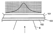
- FIG. 9 shows an enlarged view of the vicinity of the irradiation region of the electron beam B onto the target 102 in FIG. 8 and a graph showing an X-ray profile emitted to the outside by this configuration.
- the X-ray profile is represented by a graph with the position on the horizontal axis and the X-ray intensity on the vertical axis.
- the focal diameter of the electron beam B with respect to the target 102 that is, the irradiation spot diameter of the electron beam B irradiated on the surface of the target 102 becomes the focal diameter of the X-ray in the X-ray generator.
- the X-ray focal spot diameter for example, the spatial resolution of a fluoroscopic image obtained by an X-ray fluoroscopic device is improved and a clearer image is obtained.
- a target such as tungsten laminated in a thin film on one side of the X-ray irradiation window is structured as a fine columnar metal wire embedded in the light metal X-ray irradiation window (for example, Patent Documents). 1), or by forming a minute columnar hole in the X-ray irradiation window and depositing a metal as a target material in the hole (see, for example, Patent Document 2), an electron beam irradiated toward the target
- Patent Document 2 There has been proposed a technique for reducing the X-ray focal point without reducing the focal point diameter.
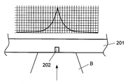
- FIG. 10 together with a schematic cross-sectional view and a graph of an X-ray profile emitted to the outside by this target structure, a structure in which a fine columnar target 202 is held in an X-ray irradiation window 201, A technique has been proposed in which the X-ray generation area is reduced and the influence of electron diffusion in the target 202 is reduced, and the X-ray focal diameter is reduced without reducing the focal diameter of the electron beam B irradiated toward the target 202. ing.
- the X-ray profile has a high intensity near the center thereof, and the X-ray focal spot diameter with respect to the focal spot diameter of the irradiating electron beam is improved.
- X-rays are also generated by irradiation of an electron beam from an X-ray irradiation window using a light element member that hardly generates X-rays, and electron diffusion covers a wider area.
- an intended X-ray focal spot diameter cannot be obtained unless the electron beam is reduced to a certain size in accordance with the size of the columnar target.
- the proposed technique requires that the location where the electron beam is applied includes a fine columnar target, and the irradiation position of the electron beam is limited. It is necessary to adjust the irradiation position of the beam.
- the target size In order to reduce the X-ray focal spot diameter, it is necessary to set the target size to, for example, the micron order or the submicron order, and the electron beam irradiation range for efficiently generating X-rays using such a fine target is extremely small. There is also a problem that the irradiation position adjustment until the target is narrowed is difficult and extremely complicated.
- the present invention has been made in view of such circumstances, and it is an object of the present invention to provide an X-ray generator capable of reliably reducing the X-ray focal diameter without depending on the focal diameter of the electron beam with respect to the target. It is said.
- the present invention has another object to simplify the adjustment of the irradiation position of the electron beam on the target.
- the X-ray generator of the present invention is formed by integrally laminating X-rays generated by irradiating a target placed in a vacuum vessel with an electron beam.
- the electron beam irradiation region of the target laminated structure including the target and the X-ray irradiation window The X-ray absorption rate in the electron beam irradiation direction is locally characterized by the formation of a low X-ray absorption rate region (Claim 1).
- the X-ray absorptance in the electron beam irradiation direction of the target laminated structure is at least in a predetermined region centered on the X-ray low absorptivity site. It is desirable to adopt a configuration (Claim 2) that becomes lower continuously or stepwise as it approaches the site.
- the target thickness in the X-ray low absorption spot is larger than the electron diffusion distance in the target (Claim 3).
- the present invention it is possible to adopt a configuration in which the difference due to the position of the X-ray absorption rate in the irradiation direction of the electron beam in the target laminated structure is due to the difference in the thickness of the target (Claim 4). it can.
- the difference in the X-ray absorption rate in the irradiation direction of the electron beam in the target laminated structure is due to the difference in the thickness of the X-ray irradiation window. ) Can also be adopted.
- the X-ray absorption layer for making the X-ray absorption rate different from the difference in the X-ray absorption rate in the irradiation direction of the electron beam in the target stack structure is the target stack structure.
- a configuration (Claim 6) obtained by stacking the layers may be employed.
- the X-ray generated in the electron beam irradiation region is localized in the irradiation region due to the difference in the X-ray absorption rate of the target laminated structure itself in which the target is stacked on the X-ray irradiation window.
- the problem is to be solved by taking out only the X-rays from various parts to the outside.
- an X-ray absorption window is formed by providing an X-ray low-absorption rate region where the X-ray absorption rate of the target laminated structure is locally low in the irradiation region of the electron beam on the target and increasing the difference from the others.
- the X-rays extracted to the outside are dominant from the X-ray low absorptivity site, and as a result, the X-ray low absorptivity site becomes a substantial X-ray focal point. Therefore, the X-ray focal spot diameter can be reliably reduced regardless of the focal spot diameter of the electron beam.
- the X-ray low absorptivity site is located in the electron beam irradiation region, and for that purpose, the X-ray low absorptivity region and the electron beam irradiation region are required.
- an electron beam other than the portion irradiated on the target is directly applied to the X-ray irradiation window. Since the focal diameter of the electron beam can be increased to the extent that it is not necessary to narrow down the electron beam so that it does not act to generate X-rays, the position adjustment becomes easier.
- the invention according to claim 2 employs a configuration in which the X-ray absorption rate of the target laminated structure is lowered as the X-ray low absorption rate portion is at the center, and the region near the X-ray low absorption rate portion approaches the portion.
- the generated X-ray intensity is monitored, and the relative position may be changed in the direction in which stronger X-rays are generated.
- the target thickness in the X-ray low absorption site of the target multilayer structure in the present invention is thicker than the electron diffusion distance in the target, Even in the X-ray low absorption rate region, the irradiated electrons do not reach the X-ray irradiation window, electron diffusion and X-ray generation do not occur in the X-ray irradiation window, and the X-ray focal spot diameter is more reliably reduced. It becomes possible to do.
- an X-ray absorptivity site where the X-ray absorption rate is locally low is provided in the electron beam irradiation region of the target laminated structure in which the target and the X-ray irradiation window are integrally laminated, Of the X-rays generated by the electron beam irradiation, only the X-rays with a low X-ray absorption rate are taken out to the outside. An X-ray focal spot diameter depending on the size of the low absorptivity site is obtained.
- FIG. 4 is a diagram illustrating a schematic cross-sectional view in the vicinity of an electron beam irradiation region of a target laminated structure according to an embodiment of the present invention and a graph showing an X-ray profile emitted to the outside by this configuration.
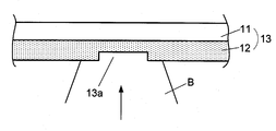
- FIG. 4 is a diagram illustrating a schematic cross-sectional view in the vicinity of an electron beam irradiation region of a target laminated structure according to an embodiment of the present invention and a graph showing an X-ray profile emitted to the outside by this configuration.
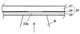
- FIG. 3 is a schematic cross-sectional view of the vicinity of an electron beam irradiation region of a target laminated structure according to an embodiment of the present invention having a function that facilitates alignment of electron beam irradiation positions.
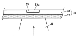
- FIG. 6 is a schematic cross-sectional view of the vicinity of an electron beam irradiation region of a target laminated structure according to another embodiment of the present invention having a function that facilitates alignment of electron beam irradiation positions.
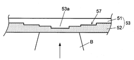
- FIG. 9 is a schematic cross-sectional view in the vicinity of an electron beam irradiation region of a target laminated structure according to still another embodiment of the present invention having a function that facilitates alignment of electron beam irradiation positions.
- FIG. 9 is a diagram illustrating an enlarged view of the vicinity of an irradiation region of an electron beam on a target in FIG. 8 and a graph showing an X-ray profile emitted to the outside by this configuration.
- a schematic cross-sectional view in the vicinity of an irradiation region of an electron beam to a target in a conventional X-ray generator having a structure in which a fine columnar target is held in an X-ray irradiation window, and an X-ray profile emitted to the outside by this configuration The figure shown together with the graph to represent.
- FIG. 1 is a diagram showing a schematic cross-sectional view of a main part of an embodiment of the present invention and a graph showing an X-ray profile emitted to the outside by this configuration.
- the basic configuration as an X-ray generator is the same as that shown in FIG. 8, and the target laminated structure is changed from that shown in FIG. 9 to that shown in FIG. It is the biggest feature.
- a target laminated structure 3 fixed so as to close one end of the vacuum vessel is constituted by an X-ray irradiation window 1 and a target 2 laminated on the inner surface of the vessel, as in FIG. 2 is irradiated with an accelerated and focused electron beam B from an electron gun in a vacuum vessel, and X-rays are generated.
- the material of the target W, Mo, Cu or the like is generally used, and as the X-ray irradiation window 1, Al, Be, diamond or the like is generally used.
- the arrow written in the electron beam B indicates the direction of irradiation of the electron beam.
- the target laminated structure 3 has an X-ray low-absorption rate region where the X-ray absorption rate in the irradiation direction (X-ray extraction direction) of the electron beam B is locally low in the irradiation region of the electron beam B to the target 2. 3a is formed.
- the X-ray low absorption rate portion 3a in this example is formed by reducing the thickness of the target 2.
- the element constituting the X-ray irradiation window 1 is a light element as compared with the element constituting the target 2, and other elements than the X-ray passing through the arrow a in the figure in the X-ray low absorptivity region 3a.
- X-rays passing through the arrow b of the site are attenuated by receiving more absorption.
- the profile of the X-rays emitted to the outside through the X-ray irradiation window 1 has a relatively strong intensity near the center corresponding to the formation position of the X-ray low absorption rate portion 3a as shown in FIG. .
- the X-ray focal spot diameter becomes smaller as compared with the case where the target having a uniform thickness shown in FIG. 9 is used.
- electrons incident on the X-ray low-absorption site 3a are diffused to attenuate X-rays generated up to the target 2 other than that site, so that an X-ray focal spot diameter of 1 ⁇ m or less is obtained.
- X-rays obliquely emitted from the electron beam B incident on the X-ray low absorption rate portion 3a are similarly attenuated for X-rays passing through portions other than the X-ray low absorption rate portion 3a. Therefore, it is also suitable for reducing the X-ray irradiation angle.
- the X-ray low-absorption rate portion 3a is recessed on the surface of the target 2 on the side in contact with the X-ray irradiation window 1 more specifically by locally reducing the thickness of the target 2.
- the X-ray low absorption rate region can also be formed by the structures shown in FIGS. 2 to 4 below.
- the surface of the target 12 opposite to the surface in contact with the X-ray irradiation window 11, that is, the surface of the target 12 on the irradiation side of the electron beam B is provided with a recess. Absorptivity site 13a is formed.
- the influence of electron diffusion on the other part of the electron beam B incident on the X-ray low absorption rate part 13a cannot be reduced, but it is suitable for increasing the X-ray irradiation angle. .
- an X-ray absorption rate is relatively obtained by laminating an X-ray absorber 24 between the X-ray irradiation window 21 and the target 22 and providing a hole in the X-ray absorber 24.
- Low X-ray low-absorption rate region 23a is formed.
- the material of the X-ray absorber 24 is preferably a metal having a higher X-ray absorption rate than the target 22.
- Pb can be used when W is used for the target 22, and W can be used when Cu is used for the target 22. . According to the structure illustrated in FIG. 3, it is possible to obtain the same effect as the example illustrated in FIG.
- the target 32 has a uniform thickness, and the X-ray irradiation window 31 has an X-ray absorption rate lower than that of the X-ray irradiation window 31.
- the X-ray low absorption rate portion 33 a in the target laminated structure 33 is formed.
- the material of the X-ray transmitting member 35 for example, Be or the like can be used when Al or diamond is used for the X-ray irradiation window 31. With this configuration, the same effect as that of the example shown in FIG. 1 can be obtained.
- the X-ray low-absorption rate site needs to be located inside the irradiation region of the electron beam B on the target.
- the electron beam is narrowed down. Therefore, it is possible to reduce the X-ray focal spot diameter. Therefore, by setting the irradiation region of the electron beam wide, it is not particularly necessary to adjust the positions of both.
- the X-ray low absorptivity region 53a is formed on the surface of the target 52 around the X-ray low absorptivity region 53a formed in the same manner as described above.
- a stepped surface 57 is formed so that the target thickness decreases stepwise as it gets closer. Also with this configuration, the same effects as described above can be obtained.
- the configuration in which the X-ray absorption rate decreases as it approaches the X-ray low absorption rate region as described above can also be applied to the target stacked structure having the structure shown in FIGS. 2 to 4.
- the surface of the target 12 on the side irradiated with the electron beam B may be formed with an inclined surface or stepped surface equivalent to that in FIG. 5, and in the structure of FIG. 4, the thickness of the X-ray irradiation window 31 increases toward the outside.
- the upper surface may be inclined or stepped in the direction. Further, in the structure of FIG. 3, as shown in FIG.
- the thickness of the X-ray absorber 64 is changed.
- the X-ray low absorption rate portion 63a may be made thinner as it approaches.
- the shape of the contour of the X-ray low-absorption rate portion viewed from the irradiation direction of the electron beam B is not particularly limited, and may be any shape such as a circle, a rectangle, or a polygon.
- the inclined surface and the stepped surface can be arbitrarily selected, such as a cone, a circular stepped shape, a pyramid or a square stepped shape.
- the thickness of the target in the X-ray low absorption rate region be larger than the electron diffusion distance.
- the electrons that have entered the X-ray low-absorption rate region do not reach the X-ray irradiation window beyond the target, and therefore the electrons diffuse widely in the X-ray irradiation window and are weak. This prevents the problem that X-rays are generated from a relatively wide area that does not occur, and makes the effects of the present invention more reliable. Since the electron diffusion distance in the target differs depending on the material and acceleration energy of the electron beam, an appropriate form and size may be adopted according to the specifications of the apparatus.
- the present invention improves the X-ray focal point by the target laminated structure itself composed of the target of the transmission type X-ray generator and the X-ray irradiation window, and X-rays in an unnecessary direction outside the X-ray irradiation window. Unlike the technique of disposing a collimator that shields the screen, the present invention does not require any structure on the outside of the vacuum vessel, so that the desired operational effect can be achieved while the structure is simple and compact. .
Landscapes
- Physics & Mathematics (AREA)
- Engineering & Computer Science (AREA)
- General Engineering & Computer Science (AREA)
- High Energy & Nuclear Physics (AREA)
- X-Ray Techniques (AREA)
Abstract
Description
図1は本発明の実施の形態の要部の模式的断面図と、この構成によって外部に放出されるX線のプロファイルを表すグラフとを併記して示す図である。この実施の形態は、X線発生装置としての基本構成は図8に示したものと同等であり、ターゲット積層構造体が図9に示したものから図1に示すものに変更されている点が最大の特徴である。
2,12,22,32,42,52,62 ターゲット
3,13,23,33,43,53,63 ターゲット積層構造体
3a,13a,23a,33a,43a,53a,63a X線低吸収率部位
24,64 X線吸収材
35 X線透過部材
46 斜面
57 階段状面
100 真空容器
101 X線照射窓
102 ターゲット
103 ターゲット積層構造体
104 電子銃
B 電子ビーム
Claims (6)
- 真空容器内に配置されたターゲットに対して電子ビームを照射することによって発生したX線を、上記ターゲットが一体に積層形成されたX線照射窓を介して電子ビームの照射方向に沿う方向に外部に取り出すX線発生装置において、
上記ターゲットと上記X線照射窓からなるターゲット積層構造体の上記電子ビームの照射領域内に、当該電子ビームの照射方向へのX線吸収率が局所的に低いX線低吸収率部位が形成されていることを特徴とするX線発生装置。 - 上記ターゲット積層構造体の上記電子ビームの照射方向へのX線吸収率が、上記X線低吸収率スポットを中心とする少なくとも所定領域において、当該X線低吸収率スポットに近づくほど連続的もしくは段階的に低くなっていることを特徴とする請求項1に記載のX線発生装置。
- 上記X線低吸収率部位におけるターゲット厚さが、当該ターゲット内での電子拡散距離よりも大きいことを特徴とする請求項1または2に記載のX線発生装置。
- 上記ターゲット積層構造体における上記電子ビームの照射方向へのX線吸収率の位置による相違が、上記ターゲットの厚さの相違によるものであることを特徴とする請求項1から3のいずれか1項に記載のX線発生装置。
- 上記ターゲット積層構造体における上記電子ビームの照射方向へのX線吸収率の位置による相違が、上記X線照射窓の厚さの相違によるものであることを特徴とする請求項1から3のいずれか1項に記載のX線発生装置。
- 上記ターゲット積層構造体における上記電子ビームの照射方向へのX線吸収率の位置による相違が、X線吸収率を相違させるためのX線吸収層を当該ターゲット積層構造体に積層したことによるものであることを特徴とする請求項1から3のいずれか1項に記載のX線発生装置。
Priority Applications (4)
| Application Number | Priority Date | Filing Date | Title |
|---|---|---|---|
| PCT/JP2015/053256 WO2016125289A1 (ja) | 2015-02-05 | 2015-02-05 | X線発生装置 |
| JP2016573013A JP6493420B2 (ja) | 2015-02-05 | 2015-02-05 | X線発生装置 |
| US15/548,489 US10453579B2 (en) | 2015-02-05 | 2015-02-05 | X-ray generator |
| CN201580075523.5A CN107210079B (zh) | 2015-02-05 | 2015-02-05 | X射线发生装置 |
Applications Claiming Priority (1)
| Application Number | Priority Date | Filing Date | Title |
|---|---|---|---|
| PCT/JP2015/053256 WO2016125289A1 (ja) | 2015-02-05 | 2015-02-05 | X線発生装置 |
Publications (1)
| Publication Number | Publication Date |
|---|---|
| WO2016125289A1 true WO2016125289A1 (ja) | 2016-08-11 |
Family
ID=56563653
Family Applications (1)
| Application Number | Title | Priority Date | Filing Date |
|---|---|---|---|
| PCT/JP2015/053256 Ceased WO2016125289A1 (ja) | 2015-02-05 | 2015-02-05 | X線発生装置 |
Country Status (4)
| Country | Link |
|---|---|
| US (1) | US10453579B2 (ja) |
| JP (1) | JP6493420B2 (ja) |
| CN (1) | CN107210079B (ja) |
| WO (1) | WO2016125289A1 (ja) |
Cited By (3)
| Publication number | Priority date | Publication date | Assignee | Title |
|---|---|---|---|---|
| WO2020084664A1 (ja) | 2018-10-22 | 2020-04-30 | キヤノンアネルバ株式会社 | X線発生装置及びx線撮影システム |
| US10825639B2 (en) | 2017-04-11 | 2020-11-03 | Siemens Healthcare Gmbh | X ray device for creation of high-energy x ray radiation |
| US12597581B2 (en) | 2021-06-30 | 2026-04-07 | Hamamatsu Photonics K.K. | X-ray generation device |
Families Citing this family (1)
| Publication number | Priority date | Publication date | Assignee | Title |
|---|---|---|---|---|
| US20210289610A1 (en) * | 2020-03-10 | 2021-09-16 | Globalfoundries U.S. Inc. | Failure analysis apparatus using x-rays |
Citations (2)
| Publication number | Priority date | Publication date | Assignee | Title |
|---|---|---|---|---|
| JPH11258400A (ja) * | 1998-03-09 | 1999-09-24 | Nippon Telegr & Teleph Corp <Ntt> | 遷移放射型x線発生装置用標的 |
| JP2011077027A (ja) * | 2009-09-04 | 2011-04-14 | Tokyo Electron Ltd | X線発生用ターゲット、x線発生装置、及びx線発生用ターゲットの製造方法 |
Family Cites Families (11)
| Publication number | Priority date | Publication date | Assignee | Title |
|---|---|---|---|---|
| IL109143A (en) * | 1993-04-05 | 1999-03-12 | Cardiac Mariners Inc | X-rays as a low-dose scanning detector by a digital X-ray imaging system |
| JP2004028845A (ja) | 2002-06-27 | 2004-01-29 | Japan Science & Technology Corp | 高輝度・高出力微小x線発生源とそれを用いた非破壊検査装置 |
| JP4601994B2 (ja) * | 2004-05-18 | 2010-12-22 | 株式会社東芝 | X線源及びその陽極 |
| NL1028481C2 (nl) * | 2005-03-08 | 2006-09-11 | Univ Delft Tech | Microröntgenbron. |
| JP2007123022A (ja) | 2005-10-27 | 2007-05-17 | Shimadzu Corp | X線源およびそれに用いられるターゲット |
| JP2008224606A (ja) * | 2007-03-15 | 2008-09-25 | Omron Corp | X線検査装置およびx線検査装置を用いたx線検査方法 |
| JP4956701B2 (ja) * | 2007-07-28 | 2012-06-20 | エスアイアイ・ナノテクノロジー株式会社 | X線管及びx線分析装置 |
| JP2015515091A (ja) * | 2012-03-16 | 2015-05-21 | ナノックス イメージング ピーエルシー | 電子放出構造を有する装置 |
| JP2014067513A (ja) * | 2012-09-25 | 2014-04-17 | Canon Inc | 放射線発生ターゲット、放射線発生ユニット及び放射線撮影システム |
| JP6140983B2 (ja) * | 2012-11-15 | 2017-06-07 | キヤノン株式会社 | 透過型ターゲット、x線発生ターゲット、x線発生管、x線x線発生装置、並びに、x線x線撮影装置 |
| CN204029760U (zh) * | 2014-08-06 | 2014-12-17 | 上海联影医疗科技有限公司 | X射线靶组件 |
-
2015
- 2015-02-05 US US15/548,489 patent/US10453579B2/en not_active Expired - Fee Related
- 2015-02-05 CN CN201580075523.5A patent/CN107210079B/zh not_active Expired - Fee Related
- 2015-02-05 JP JP2016573013A patent/JP6493420B2/ja not_active Expired - Fee Related
- 2015-02-05 WO PCT/JP2015/053256 patent/WO2016125289A1/ja not_active Ceased
Patent Citations (2)
| Publication number | Priority date | Publication date | Assignee | Title |
|---|---|---|---|---|
| JPH11258400A (ja) * | 1998-03-09 | 1999-09-24 | Nippon Telegr & Teleph Corp <Ntt> | 遷移放射型x線発生装置用標的 |
| JP2011077027A (ja) * | 2009-09-04 | 2011-04-14 | Tokyo Electron Ltd | X線発生用ターゲット、x線発生装置、及びx線発生用ターゲットの製造方法 |
Cited By (6)
| Publication number | Priority date | Publication date | Assignee | Title |
|---|---|---|---|---|
| US10825639B2 (en) | 2017-04-11 | 2020-11-03 | Siemens Healthcare Gmbh | X ray device for creation of high-energy x ray radiation |
| WO2020084664A1 (ja) | 2018-10-22 | 2020-04-30 | キヤノンアネルバ株式会社 | X線発生装置及びx線撮影システム |
| KR20210057788A (ko) | 2018-10-22 | 2021-05-21 | 캐논 아네르바 가부시키가이샤 | X선 발생 장치 및 x선 촬영 시스템 |
| TWI732319B (zh) * | 2018-10-22 | 2021-07-01 | 日商佳能安內華股份有限公司 | X射線產生裝置、x射線攝影系統及x射線焦點徑之調整方法 |
| US11244801B2 (en) | 2018-10-22 | 2022-02-08 | Canon Anelva Corporation | X-ray generation device and X-ray image capture system |
| US12597581B2 (en) | 2021-06-30 | 2026-04-07 | Hamamatsu Photonics K.K. | X-ray generation device |
Also Published As
| Publication number | Publication date |
|---|---|
| US10453579B2 (en) | 2019-10-22 |
| CN107210079B (zh) | 2020-03-20 |
| US20180005721A1 (en) | 2018-01-04 |
| CN107210079A (zh) | 2017-09-26 |
| JPWO2016125289A1 (ja) | 2018-01-11 |
| JP6493420B2 (ja) | 2019-04-03 |
Similar Documents
| Publication | Publication Date | Title |
|---|---|---|
| US20170003234A1 (en) | Illumination and imaging device for high-resolution x-ray microscopy with high photon energy | |
| KR101968377B1 (ko) | X선 발생 장치 및 x선 발생 방법 | |
| KR102391598B1 (ko) | X선 콜리메이터 | |
| JP6493420B2 (ja) | X線発生装置 | |
| JP4750938B2 (ja) | 微細加工されたx線画像コントラストグリッドおよびその製造方法 | |
| JP2013051164A (ja) | 透過型x線発生装置 | |
| US20170018392A1 (en) | Composite target and x-ray tube with the composite target | |
| US20140362972A1 (en) | X-ray generator and x-ray imaging apparatus | |
| JP2012505399A (ja) | グリッド、及び特にマンモグラフィ用x線である電磁放射線の選択透過のためのグリッドの製造方法 | |
| US6177237B1 (en) | High resolution anti-scatter x-ray grid and laser fabrication method | |
| JP2016509231A (ja) | 光学ミラー、x線蛍光分析デバイス及びx線蛍光分析のための方法 | |
| Ivanov et al. | Nanostructured plasmas for enhanced gamma emission at relativistic laser interaction with solids | |
| JP2020530107A (ja) | 収束x線イメージング形成装置及び方法 | |
| US8761346B2 (en) | Multilayer total internal reflection optic devices and methods of making and using the same | |
| US20170229204A1 (en) | X-ray beam collimator | |
| US20140112449A1 (en) | System and method for collimating x-rays in an x-ray tube | |
| JP6422050B2 (ja) | X線光学系基材、及びその製造方法 | |
| JPH05119199A (ja) | レーザプラズマx線源用ターゲツト | |
| CN108696977B (zh) | 用于产生高能量x射线辐射的x射线设备 | |
| JP6110209B2 (ja) | X線発生用ターゲット及びx線発生装置 | |
| KR20260004398A (ko) | 이차 방사선 완화 기술 | |
| JP2014130036A (ja) | 光学装置 | |
| JPH01185498A (ja) | X線ガイドチューブ | |
| KR101623058B1 (ko) | 레이저 플라즈마 X-ray 광원의 팽창 방지를 위한 구조를 갖는 표적 | |
| KR20140140145A (ko) | 경사진 다층 박막 거울 및 그 제조 방법 |
Legal Events
| Date | Code | Title | Description |
|---|---|---|---|
| 121 | Ep: the epo has been informed by wipo that ep was designated in this application |
Ref document number: 15881106 Country of ref document: EP Kind code of ref document: A1 |
|
| ENP | Entry into the national phase |
Ref document number: 2016573013 Country of ref document: JP Kind code of ref document: A |
|
| WWE | Wipo information: entry into national phase |
Ref document number: 15548489 Country of ref document: US |
|
| NENP | Non-entry into the national phase |
Ref country code: DE |
|
| 122 | Ep: pct application non-entry in european phase |
Ref document number: 15881106 Country of ref document: EP Kind code of ref document: A1 |