WO2016121946A1 - 多焦点分光計測装置、及び多焦点分光計測装置用光学系 - Google Patents
多焦点分光計測装置、及び多焦点分光計測装置用光学系 Download PDFInfo
- Publication number
- WO2016121946A1 WO2016121946A1 PCT/JP2016/052707 JP2016052707W WO2016121946A1 WO 2016121946 A1 WO2016121946 A1 WO 2016121946A1 JP 2016052707 W JP2016052707 W JP 2016052707W WO 2016121946 A1 WO2016121946 A1 WO 2016121946A1
- Authority
- WO
- WIPO (PCT)
- Prior art keywords
- multifocal
- objective
- light
- sample
- spectroscopic measurement
- Prior art date
Links
- 238000005259 measurement Methods 0.000 title claims abstract description 132
- 230000003287 optical effect Effects 0.000 title claims abstract description 39
- 239000011159 matrix material Substances 0.000 claims description 26
- 238000006243 chemical reaction Methods 0.000 claims description 22
- 238000004611 spectroscopical analysis Methods 0.000 claims description 10
- 230000001678 irradiating effect Effects 0.000 claims description 9
- 239000006185 dispersion Substances 0.000 claims description 4
- 230000035945 sensitivity Effects 0.000 abstract description 12
- 238000001069 Raman spectroscopy Methods 0.000 description 23
- 238000010586 diagram Methods 0.000 description 12
- 239000013307 optical fiber Substances 0.000 description 12
- 238000001228 spectrum Methods 0.000 description 8
- 239000000835 fiber Substances 0.000 description 7
- 239000000463 material Substances 0.000 description 5
- 238000000691 measurement method Methods 0.000 description 5
- 238000012986 modification Methods 0.000 description 4
- 230000004048 modification Effects 0.000 description 4
- 238000002474 experimental method Methods 0.000 description 3
- 238000002189 fluorescence spectrum Methods 0.000 description 3
- 230000004907 flux Effects 0.000 description 3
- 238000004519 manufacturing process Methods 0.000 description 3
- LFQSCWFLJHTTHZ-UHFFFAOYSA-N Ethanol Chemical compound CCO LFQSCWFLJHTTHZ-UHFFFAOYSA-N 0.000 description 2
- 238000004458 analytical method Methods 0.000 description 2
- 238000000701 chemical imaging Methods 0.000 description 2
- 238000013537 high throughput screening Methods 0.000 description 2
- 238000003384 imaging method Methods 0.000 description 2
- 238000001237 Raman spectrum Methods 0.000 description 1
- VYXSBFYARXAAKO-WTKGSRSZSA-N chembl402140 Chemical compound Cl.C1=2C=C(C)C(NCC)=CC=2OC2=C\C(=N/CC)C(C)=CC2=C1C1=CC=CC=C1C(=O)OCC VYXSBFYARXAAKO-WTKGSRSZSA-N 0.000 description 1
- 230000007423 decrease Effects 0.000 description 1
- 238000011161 development Methods 0.000 description 1
- 239000011521 glass Substances 0.000 description 1
- 239000000203 mixture Substances 0.000 description 1
- 238000012545 processing Methods 0.000 description 1
- 239000007787 solid Substances 0.000 description 1
- 230000003595 spectral effect Effects 0.000 description 1
- 239000002699 waste material Substances 0.000 description 1
Images


Classifications
-
- G—PHYSICS
- G01—MEASURING; TESTING
- G01J—MEASUREMENT OF INTENSITY, VELOCITY, SPECTRAL CONTENT, POLARISATION, PHASE OR PULSE CHARACTERISTICS OF INFRARED, VISIBLE OR ULTRAVIOLET LIGHT; COLORIMETRY; RADIATION PYROMETRY
- G01J3/00—Spectrometry; Spectrophotometry; Monochromators; Measuring colours
- G01J3/02—Details
- G01J3/0205—Optical elements not provided otherwise, e.g. optical manifolds, diffusers, windows
- G01J3/0216—Optical elements not provided otherwise, e.g. optical manifolds, diffusers, windows using light concentrators or collectors or condensers
-
- G—PHYSICS
- G01—MEASURING; TESTING
- G01J—MEASUREMENT OF INTENSITY, VELOCITY, SPECTRAL CONTENT, POLARISATION, PHASE OR PULSE CHARACTERISTICS OF INFRARED, VISIBLE OR ULTRAVIOLET LIGHT; COLORIMETRY; RADIATION PYROMETRY
- G01J3/00—Spectrometry; Spectrophotometry; Monochromators; Measuring colours
- G01J3/02—Details
- G01J3/0205—Optical elements not provided otherwise, e.g. optical manifolds, diffusers, windows
- G01J3/0208—Optical elements not provided otherwise, e.g. optical manifolds, diffusers, windows using focussing or collimating elements, e.g. lenses or mirrors; performing aberration correction
-
- G—PHYSICS
- G01—MEASURING; TESTING
- G01J—MEASUREMENT OF INTENSITY, VELOCITY, SPECTRAL CONTENT, POLARISATION, PHASE OR PULSE CHARACTERISTICS OF INFRARED, VISIBLE OR ULTRAVIOLET LIGHT; COLORIMETRY; RADIATION PYROMETRY
- G01J3/00—Spectrometry; Spectrophotometry; Monochromators; Measuring colours
- G01J3/02—Details
- G01J3/0205—Optical elements not provided otherwise, e.g. optical manifolds, diffusers, windows
- G01J3/0218—Optical elements not provided otherwise, e.g. optical manifolds, diffusers, windows using optical fibers
- G01J3/0221—Optical elements not provided otherwise, e.g. optical manifolds, diffusers, windows using optical fibers the fibers defining an entry slit
-
- G—PHYSICS
- G01—MEASURING; TESTING
- G01J—MEASUREMENT OF INTENSITY, VELOCITY, SPECTRAL CONTENT, POLARISATION, PHASE OR PULSE CHARACTERISTICS OF INFRARED, VISIBLE OR ULTRAVIOLET LIGHT; COLORIMETRY; RADIATION PYROMETRY
- G01J3/00—Spectrometry; Spectrophotometry; Monochromators; Measuring colours
- G01J3/02—Details
- G01J3/0205—Optical elements not provided otherwise, e.g. optical manifolds, diffusers, windows
- G01J3/0229—Optical elements not provided otherwise, e.g. optical manifolds, diffusers, windows using masks, aperture plates, spatial light modulators or spatial filters, e.g. reflective filters
-
- G—PHYSICS
- G01—MEASURING; TESTING
- G01J—MEASUREMENT OF INTENSITY, VELOCITY, SPECTRAL CONTENT, POLARISATION, PHASE OR PULSE CHARACTERISTICS OF INFRARED, VISIBLE OR ULTRAVIOLET LIGHT; COLORIMETRY; RADIATION PYROMETRY
- G01J3/00—Spectrometry; Spectrophotometry; Monochromators; Measuring colours
- G01J3/02—Details
- G01J3/0289—Field-of-view determination; Aiming or pointing of a spectrometer; Adjusting alignment; Encoding angular position; Size of measurement area; Position tracking
-
- G—PHYSICS
- G01—MEASURING; TESTING
- G01J—MEASUREMENT OF INTENSITY, VELOCITY, SPECTRAL CONTENT, POLARISATION, PHASE OR PULSE CHARACTERISTICS OF INFRARED, VISIBLE OR ULTRAVIOLET LIGHT; COLORIMETRY; RADIATION PYROMETRY
- G01J3/00—Spectrometry; Spectrophotometry; Monochromators; Measuring colours
- G01J3/02—Details
- G01J3/0294—Multi-channel spectroscopy
-
- G—PHYSICS
- G01—MEASURING; TESTING
- G01J—MEASUREMENT OF INTENSITY, VELOCITY, SPECTRAL CONTENT, POLARISATION, PHASE OR PULSE CHARACTERISTICS OF INFRARED, VISIBLE OR ULTRAVIOLET LIGHT; COLORIMETRY; RADIATION PYROMETRY
- G01J3/00—Spectrometry; Spectrophotometry; Monochromators; Measuring colours
- G01J3/12—Generating the spectrum; Monochromators
- G01J3/18—Generating the spectrum; Monochromators using diffraction elements, e.g. grating
-
- G—PHYSICS
- G01—MEASURING; TESTING
- G01J—MEASUREMENT OF INTENSITY, VELOCITY, SPECTRAL CONTENT, POLARISATION, PHASE OR PULSE CHARACTERISTICS OF INFRARED, VISIBLE OR ULTRAVIOLET LIGHT; COLORIMETRY; RADIATION PYROMETRY
- G01J3/00—Spectrometry; Spectrophotometry; Monochromators; Measuring colours
- G01J3/28—Investigating the spectrum
- G01J3/30—Measuring the intensity of spectral lines directly on the spectrum itself
- G01J3/36—Investigating two or more bands of a spectrum by separate detectors
-
- G—PHYSICS
- G01—MEASURING; TESTING
- G01J—MEASUREMENT OF INTENSITY, VELOCITY, SPECTRAL CONTENT, POLARISATION, PHASE OR PULSE CHARACTERISTICS OF INFRARED, VISIBLE OR ULTRAVIOLET LIGHT; COLORIMETRY; RADIATION PYROMETRY
- G01J3/00—Spectrometry; Spectrophotometry; Monochromators; Measuring colours
- G01J3/28—Investigating the spectrum
- G01J3/44—Raman spectrometry; Scattering spectrometry ; Fluorescence spectrometry
- G01J3/4406—Fluorescence spectrometry
-
- G—PHYSICS
- G01—MEASURING; TESTING
- G01N—INVESTIGATING OR ANALYSING MATERIALS BY DETERMINING THEIR CHEMICAL OR PHYSICAL PROPERTIES
- G01N21/00—Investigating or analysing materials by the use of optical means, i.e. using sub-millimetre waves, infrared, visible or ultraviolet light
- G01N21/01—Arrangements or apparatus for facilitating the optical investigation
- G01N21/03—Cuvette constructions
-
- G—PHYSICS
- G01—MEASURING; TESTING
- G01N—INVESTIGATING OR ANALYSING MATERIALS BY DETERMINING THEIR CHEMICAL OR PHYSICAL PROPERTIES
- G01N21/00—Investigating or analysing materials by the use of optical means, i.e. using sub-millimetre waves, infrared, visible or ultraviolet light
- G01N21/62—Systems in which the material investigated is excited whereby it emits light or causes a change in wavelength of the incident light
- G01N21/63—Systems in which the material investigated is excited whereby it emits light or causes a change in wavelength of the incident light optically excited
- G01N21/64—Fluorescence; Phosphorescence
- G01N21/645—Specially adapted constructive features of fluorimeters
- G01N21/6456—Spatial resolved fluorescence measurements; Imaging
- G01N21/6458—Fluorescence microscopy
-
- G—PHYSICS
- G01—MEASURING; TESTING
- G01N—INVESTIGATING OR ANALYSING MATERIALS BY DETERMINING THEIR CHEMICAL OR PHYSICAL PROPERTIES
- G01N21/00—Investigating or analysing materials by the use of optical means, i.e. using sub-millimetre waves, infrared, visible or ultraviolet light
- G01N21/62—Systems in which the material investigated is excited whereby it emits light or causes a change in wavelength of the incident light
- G01N21/63—Systems in which the material investigated is excited whereby it emits light or causes a change in wavelength of the incident light optically excited
- G01N21/65—Raman scattering
Definitions
- the present invention relates to a multifocal spectroscopic measurement apparatus that simultaneously measures signal light such as fluorescence and Raman light from a plurality of points, and an optical system for the multifocal spectroscopic measurement apparatus.
- HTS high-throughput screening
- spectroscopic measurement in which the spectrum of each sample is acquired by spectrally separating the signal light emitted from each sample, and the composition and molecular structure of each sample are analyzed from the spectrum.
- the signal light includes fluorescence and Raman light emitted from each sample by irradiating the sample with irradiation light, chemiluminescence emitted from the sample without irradiating the sample with irradiation light, and the like.
- Patent Document 1 and Non-Patent Document 1 describe a multifocal spectroscopic measurement apparatus that has no possibility of being applied to the multisample simultaneous measurement method, although it does not describe the multisample simultaneous measurement method.
- This device is a kind of so-called "Raman spectroscopic microscope", which is a position obtained by dividing the irradiation light into multiple parts by a microlens array, which will be described later, and irradiating each irradiation light to different positions on one sample
- Each Raman light is dispersed and the intensity of the Raman light having a predetermined Raman shift is mapped, whereby the distribution of sample components corresponding to the Raman shift is acquired as an image.
- each irradiation light is irradiated to each different sample one by one and applied to simultaneous measurement of multiple samples. .
- the laser light generated by the laser light source 91 is divided into a plurality of light beams by a microlens array 92 in which eight microlenses 921 are arranged in a matrix form vertically and horizontally.
- a microlens array 92 in which eight microlenses 921 are arranged in a matrix form vertically and horizontally.
- Each of the luminous fluxes is reflected by the edge filter 93, passes through a pinhole array 94 provided with a hole corresponding to each luminous flux, and a relay lens 95 and an objective lens 96 common to each luminous flux,
- the sample S is irradiated.
- the sample S emits signal light of the number of light beams corresponding to the plurality of light beams obtained by dividing the irradiation light. Reflected light having the same wavelength as the irradiation light and Raman light having a wavelength different from that of the irradiation light are superimposed on the signal light.
- the signal light passes through the holes of the objective lens 96, the relay lens 95, and the pinhole array 94 and reaches the edge filter 93. In the edge filter 93, the reflected light is reflected without passing due to the difference in wavelength, and only the Raman light passes.
- the Raman light beam that has passed through the edge filter 93 passes through a lens optical system 97 including a pair of two lenses, and then a fiber bundle 98 in which the same number of optical fibers as the microlenses 921 are bundled in phase with the microlens array 92. Is incident on.
- the input ends of the plurality of optical fibers in the fiber bundle 98 are arranged in a matrix, and Raman light is incident on each input end one by one.
- the output ends of the fiber bundle 98 are arranged in a line, and the light emitted from each output end is split by the spectroscope 99.
- Patent Document 2 a sample S is irradiated with irradiation light from one objective lens, signal light (Raman light) emitted from the sample S is received by a plurality of optical fibers in a fiber bundle, and an output end of each optical fiber is received.
- a multi-point simultaneous spectroscopic measurement device that splits light emitted from a spectroscope with a spectroscope is described.
- This apparatus is different from the apparatuses described in Patent Document 1 and Non-Patent Document 1 in that the irradiation light is not divided and the signal light is not divided until it reaches the fiber bundle.
- Patent Document 2 does not describe a multi-sample simultaneous measurement method.
- the signal light generated from the sample is isotropically emitted in a spherical shape, only a part of the signal light can be collected by the objective lens, but in order to perform measurement with high sensitivity, the signal light A higher collection rate is desirable.
- the objective is to obtain Raman light from a plurality of different positions in one sample, and therefore the observation target region is relatively small. Since the size of the observation target region in this apparatus is about a few tens of ⁇ m square, there is no problem in measurement sensitivity for that purpose. However, in order to apply to simultaneously measuring a plurality of samples, observation must be performed in a wider area. Specifically, in a sample holder called “multiwell” that is commercially available for simultaneous measurement of multiple samples, several tens to several hundreds of wells for holding individual samples are arranged in a matrix form vertically and horizontally.
- the overall size is several centimeters to several tens of centimeters per side.
- the magnification of the objective lens must be lowered, and the measurement sensitivity is lowered. End up. Therefore, this apparatus is not suitable for application to multi-sample simultaneous measurement.
- the problem to be solved by the present invention is to provide a multifocal spectroscopic measurement apparatus and an optical system for a multifocal spectroscopic measurement apparatus that can perform multisample simultaneous measurement with high sensitivity without being limited by magnification. is there.
- the multifocal spectroscopic measurement device which has been made to solve the above-mentioned problems, introduces signal light emitted from a plurality of predetermined observation regions in a sample placed in a sample placement portion into a spectroscope.
- a device that performs A plurality of objective condensing units provided one by one at a position optically opposed to each of the plurality of observation regions;
- One spectroscopic input unit provided for each of the plurality of objective condensing units, and a spectroscope input unit for inputting the signal light that has passed through the corresponding objective condensing unit to the spectroscope.
- the “position optically opposed to the observation area” refers to the position where the signal light from the observation area arrives.
- the position is (literally) a position relative to the observation region.
- an optical element for example, a magnification conversion unit described later
- each of the plurality of objective condensing units is provided optically relative to one observation region in the sample.
- the plurality of observation regions may be all in one sample, may be dispersed in the plurality of samples, or may be only one for one sample.
- one objective condenser unit corresponds to one observation region, and each objective condenser unit collects signal light from the optically opposed observation regions.
- the signal light collected by each objective condensing unit is input to the corresponding spectrometer input unit. Thereby, the spectral measurement of the signal light is performed for each observation region.
- Each spectroscope input unit may be arranged (literally) relative to the corresponding objective condensing unit.
- the objective condensing unit and the spectroscope input are similar to those between the observation region and the objective condensing unit. You may arrange
- NA n ⁇ sin ⁇
- NA NA ⁇ sin ⁇ ′
- each objective condensing unit only needs to observe only one observation region, so that many samples and large samples can be observed simultaneously.
- the magnification can be lowered, that is, the observable area can be increased, and the numerical aperture NA of each objective focusing section can be increased, that is, the measurement sensitivity can be increased.
- the multifocal spectroscopic measurement device includes a spectroscope-side condensing unit between a part or all of the plurality of objective condensing units and the corresponding spectroscope input unit.
- a point in the observation region that is optically opposed to the objective condensing unit exists at a position where the signal light between the optical unit and the spectroscopic-side condensing unit passes through the objective condensing unit to be focused. It is desirable that the spectroscope input unit corresponding to the objective condensing unit is present at a position where the signal light passes through the spectroscope-side condensing unit to be focused.
- the measurement sensitivity can be optimized. That is, since the numerical aperture NA of the objective condensing unit can be increased regardless of the magnification, the signal light collection efficiency can be increased, and the numerical aperture NA of the spectroscope-side condensing unit can be increased regardless of the magnification. Since it can be set, the signal light can be incident on the spectroscope with an optimum numerical aperture NA with high utilization efficiency.
- the signal light from the observation region can be efficiently introduced into the spectrometer input section. Furthermore, by eliminating the trade-off between numerical aperture NA and magnification, the size and interval of signal light incident on the spectrometer can be determined according to the configuration of the spectrometer. However, the number of measurement points can be increased arbitrarily. These cannot be realized by the conventional imaging optical system as shown in FIG.
- a light source for irradiating the sample with the irradiation light is provided in the multifocal spectrometer according to the present invention.
- the light source may be disposed at a position where the sample is irradiated with irradiation light through the objective condensing unit, or may be disposed at a position where the sample is irradiated with irradiation light without passing through the objective condensing unit. .
- the arrangement of the plurality of observation regions and the objective condensing unit optically opposed to each observation region may be one-dimensional or two-dimensional. Further, the observation region and the objective light converging unit may be arranged at regular intervals or non-equal intervals. In the case where the observation regions and the objective condensing units are arranged two-dimensionally, the arrangement may be random (random), square lattice (matrix), triangular lattice, radial, etc. May be arranged in order.
- the multifocal spectroscopic measurement device includes the plurality of objective condensing units in the vertical and horizontal directions.
- each of the plurality of spectrometer-side condensers is optically opposed to the objective condenser in a matrix form vertically and horizontally. It is desirable to provide a spectroscope-side condensing unit array that is arranged.
- the multifocal spectroscopic measurement apparatus not only the signal light but also the irradiation light reflected by the sample can enter the spectroscope input section only with the above-described configuration.
- Irradiation light incident on the spectroscope may be excluded by analysis processing.
- the signal light is Raman light
- the wavelength is different from that of the irradiation light. Therefore, if the filter is used, only the irradiation light is removed. can do. The same applies to fluorescence having a wavelength different from the irradiation light.
- the multifocal spectroscopic measurement device along with the light source that irradiates the sample with irradiation light, the light having the wavelength of the signal light provided between the sample placement unit and the spectrometer input unit is transmitted.
- a filter that reflects light having the wavelength of the irradiation light can be provided.
- the number of irradiation lights incident on the filter may be one, but a plurality of irradiation lights are irradiated on the filter, and the plurality of irradiation lights after being reflected by the filter are irradiated on different objective condensing units. It is desirable that the filter is arranged as described above.
- the plurality of irradiation lights may be generated based on a plurality of different light sources, or may be generated by branching a single light source into a plurality. Since the size of the filter can be reduced by using a plurality of irradiation lights, the surface accuracy of the filter can be increased and the manufacturing cost can be reduced compared to the case of using a large area filter with a single irradiation light. it can.
- the intensity of the irradiation light on each sample can be increased, and the sensitivity of spectroscopic measurement is also increased.
- the filter is disposed between the objective condensing unit and the spectroscope input unit.
- the irradiation light emitted from the light source is arranged so as to be reflected in the direction of the optical axis of the objective condensing unit. Thereby, irradiation light is condensed on the observation region through the objective condensing unit, and the irradiation light can be used without omission.
- a magnification conversion unit for enlarging or reducing an image of the signal light from each of the plurality of observation regions is provided between the plurality of observation regions and the plurality of objective condensing units. Can be provided. By using the magnification conversion unit, a large number of narrow observation areas can be measured simultaneously.
- the multifocal spectroscopic measurement device according to the present invention enlarges or reduces the image of the signal light from each of the plurality of objective condensers between the plurality of objective condensers and the spectrometer input unit. You may have a spectroscope input part magnification conversion part.
- magnification conversion unit and the spectroscope input unit side magnification conversion unit use a condensing unit consisting of one lens or the like, or a condensing unit consisting of a set of lenses arranged in the traveling direction of the signal light. Can do.
- the multifocal spectroscopic measurement device is:
- the spectroscope input unit is arranged at one point of the matrix corresponding to each of the plurality of objective condensing units,
- a configuration in which the rows and columns of the matrix are non-parallel to the wavelength dispersion direction of the spectroscopic element included in the spectroscope may be employed.
- a diffraction grating, a prism, or the like can be used as the spectroscopic element. With this configuration, it is possible to obtain diffracted light from each signal light without overlapping each other using only one spectroscopic element.
- This spectroscopic optical system can be used not only in the optical system for a multifocal spectroscopic measurement apparatus according to the present invention but also in the apparatuses described in Patent Document 1 and Patent Document 2, for example.
- the multifocal spectroscopic measurement apparatus includes a moving unit that moves a relative position of the sample and the plurality of objective light collecting units along a plane including the sample arranged in the sample arranging unit. it can. Thereby, it is possible to observe the sample over a wider area than in the case where the moving means is not used, and it is possible to perform spectroscopic imaging for imaging spectroscopic data.
- the relative position of the sample and the plurality of objective condensing units may be linear (one-dimensional), planar (two-dimensional), or three-dimensional (three-dimensional).
- An optical system for a multifocal spectroscopic measurement apparatus is an optical system used in an apparatus for spectroscopic analysis by introducing signal light emitted from a plurality of predetermined observation regions in a sample arranged in a sample arrangement unit into a spectrometer. Because A plurality of objective condensing units provided so as to be arranged one by one at positions optically opposed to each of the plurality of observation regions in a state of being mounted on the apparatus.
- the present invention it is possible to obtain a multifocal spectroscopic measurement apparatus that can simultaneously measure a large number of samples or a large sample with high sensitivity without being limited by magnification.
- FIG. 1 is a schematic configuration diagram showing a first embodiment of a multifocal spectroscopic measurement apparatus according to the present invention.
- the schematic block diagram which shows the light source and beam diameter expansion optical system which are used in 1st Example.
- the longitudinal cross-sectional view which shows another example of a lens array.
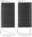
- the CCD image and graph which show the result of having measured (a) fluorescence spectrum and (b) Raman spectrum using the multifocal spectroscopic measurement apparatus of 1st Example.
- the schematic block diagram which shows 2nd Example of the multifocal spectroscopy measuring device which concerns on this invention.
- the schematic block diagram which shows 3rd Example of the multifocal spectroscopy measuring device which concerns on this invention.
- Schematic configuration diagram (a) showing an example of a spectroscope used in the multifocal spectroscopic measurement apparatus of each embodiment and other multifocal spectroscopic measurement apparatuses, and signal light emitted from the pinhole array and diffracted light incident on the light receiver Figure (b) shown.
- a CCD image (a) showing a result of simultaneous spectroscopy of a plurality of signal lights using the spectrometer of FIG. 13, a partially enlarged image (b), and an extracted spectrum (c).
- the schematic block diagram which shows an example of the conventional multifocal spectroscopic measurement apparatus.
- the multifocal spectroscopic measurement apparatus 10 of the first embodiment has wells for storing the sample S arranged vertically and horizontally in a matrix.
- the bottom surface of the multiwell MW and the sample holder 13 are made of glass that is transparent to irradiation light and signal light.
- an objective lens array (object condenser part array) 11 in which a plurality of objective lenses (object condenser parts) 111 are arranged vertically and horizontally in a matrix.
- the plurality of objective lenses 111 are provided so as to face each well in a state where the multi-well MW is held in the sample holder 13. Each of these wells serves as an observation region for one sample S. Each objective lens 111 is disposed at a position where the objective lens 111 is focused in the opposite well in the multiwell MW held by the sample holder 13 when parallel light as signal light is incident from the opposite side of the sample holder 13. Yes.
- the multifocal spectroscopic measurement apparatus 10 includes a second lens array (a spectroscope side lens array, a spectroscope side condensing part array) 12 facing the objective lens array 11.
- a second lens (a spectroscope side lens, a spectroscope side condensing unit) 121 provided one by one relative to each of the plurality of objective lenses 111 is arranged in a matrix form vertically and horizontally. It is what.
- the multifocal spectroscopic measurement apparatus 10 has a spectroscope input unit 151 provided one by one for each of the plurality of second lenses 121.
- Each spectroscope input unit 151 is an input end of one optical fiber.
- Each spectroscope input unit 151 is arranged at a position where signal light (parallel light) incident on the second lens 121 facing from the opposite side of the spectroscope input unit 151 is focused on the spectroscope input unit 151.
- the spectroscope input section aggregate 15 is formed by arranging the spectroscope input sections 151 in a matrix in the vertical and horizontal directions relative to the second lens 121.
- the output ends of all the optical fibers are arranged in a line, and are arranged so that light from each output end is irradiated to different positions on the surface of the diffraction grating in the spectrometer 17.
- a filter 14 that transmits light having a wavelength within a predetermined wavelength band and reflects light having a wavelength within the other wavelength band.
- the predetermined wavelength band does not include the wavelength of the irradiation light but includes the wavelength of the signal light. Therefore, the filter 14 reflects the irradiation light and transmits the signal light.
- the filter 14 is composed of two rectangular plate-like members. One plate-like member covers half of the rows of the objective lenses 111 (four rows on the left side in FIG. 1), and the end of the row of the objective lenses 111 is farther from the objective lens array 11 than the center of the objective lens array 11. As described above, the optical axis of the objective lens 111 is inclined by 45 °.
- the other plate-like member covers the other half of the rows of the objective lenses 111 (four rows on the right side in FIG. 1) and is 90 ° with respect to the one plate-like member (45 with respect to the optical axis of the objective lens 111). °) Inclined.
- the multifocal spectroscopic measurement apparatus 10 of this embodiment has two light sources (laser light sources) 19 for irradiation light.
- a diameter expanding lens 1911 for expanding the diameter of the laser light from the light source 19 and a laser beam whose diameter is expanded by the diameter expanding lens 1911 are converted into parallel beams.
- a diameter expanding optical system 191 including a beam forming lens 1912 is provided.
- One of the two light sources 19 irradiates one plate-like member of the filter 14 with laser light from a direction (left side in FIG.
- the other plate-like member of the filter 14 is arranged so as to irradiate laser light from a direction (right side in FIG. 1) of 90 ° with respect to the optical axis of the objective lens 111.
- FIG. 1 eight objective lenses 111 are illustrated vertically and horizontally, but the number of objective lenses 111 is not limited to the illustrated example.
- a commercially available multiwell there are 16 wells arranged vertically and 24 horizontally, for a total of 384 (24 x 16). In this case, 16 objective lenses 111 may be arranged vertically and 24 horizontally.
- the second lens 121 and the spectroscope input unit 151 are similarly arranged.
- the overall size of this commercially available multiwell is 72 mm long and 108 mm wide, and its area is much larger, about 10 7 times the area of the entire observation region, which is a dozen ⁇ m square in Patent Document 1. .
- FIG. 1 shows a configuration in which each objective lens 111 is provided independently in the objective lens array 11.
- a plurality of objective lenses 111 are provided on the surface of a plate 112 that is transparent to irradiation light and signal light.
- a plurality of convex portions 111C may be provided. Thereby, each convex part 111C can be used as an objective lens, and the plate material 112 and the plurality of convex parts 111C can be combined and handled as an integrated objective lens array 11P. The same applies to the second lens array 12.
- the sample S absorbs the energy of the irradiation light or scatters the irradiation light, and emits signal light such as fluorescence or Raman light having a wavelength different from that of the irradiation light.
- the signal light is indicated by a solid arrow on the optical path in the figure.
- the signal light emitted from each sample S is collected by the objective lens 111 facing the well (observation region) in which the sample is accommodated.
- the signal light collected by each objective lens 111 passes through the filter 14 as parallel light and enters the second lens 121.
- the objective lens 111 collects not only the signal light but also the irradiation light (reflected light) reflected by the sample S. However, since the reflected light is removed by the filter 14, it is incident on the second lens 121. do not do.
- each second lens 121 The signal light incident on each second lens 121 is collected at the opposite spectrometer input unit 151, that is, the input end of the optical fiber, and irradiated to the spectrometer 17 from the output end of the optical fiber. Each signal light is diffracted on the surface of the diffraction grating of the spectroscope 17 and dispersed at different positions on the light receiving surface of the detector for each wavelength.
- each objective lens 111 observes only one well (observation region). Therefore, since the observation area of each objective lens 111 can be made smaller than when observing all observation areas with a single objective lens, the magnification can be increased, and The numerical aperture NA can be increased. This increases the collection rate, which is the ratio of the amount of light collected by the objective lens, out of the total amount of signal light emitted by the sample in each observation region, and increases the measurement sensitivity.
- the filter 14 composed of a plurality of plate-like members
- the area of the plate-like members per sheet can be made smaller than a filter using only one plate-like member. For this reason, the surface accuracy of the plate-like member can be easily increased, thereby reducing the cost.
- each of the two laser light sources irradiates irradiation light to half of the plurality of objective lenses 111, irradiation is performed more than the case where all the objective lenses 111 are irradiated with irradiation light from one laser light source.
- the intensity of light increases. As a result, the intensity of the signal light is increased and the measurement sensitivity is increased.
- two irradiation lights are used, but three or more irradiation lights may be used.
- the well containing the sample is only a part of the entire multi-well MW, but the total observation area including the 96 observation areas is still 36.0 mm in length and 54.0 mm in width. It has an area approximately 10 7 times the total observation area in Document 1.
- Fig. 4 shows the experimental results.
- (a) is a result of fluorescence measurement
- (b) is a result of Raman light measurement.
- the upper photo is a diffracted light from the diffraction grating taken by the spectroscope 17 with a CCD camera.
- 96 lines extending in the horizontal direction with brightness and darkness are arranged in the vertical direction. The 96 lines show the (a) fluorescence spectrum and (b) scattering spectrum of signal light from different wells, the horizontal position corresponds to the wavelength of the diffracted light, and the brightness of the line is the intensity of the spectrum. Is shown.
- the graphs shown on the lower side of (a) and (b) show the fluorescence spectrum or the scattering spectrum shown on the 14th from the top in the upper photograph. As shown in these photographs and graphs, clear spectra of fluorescence and Raman light were obtained by the multifocal spectrometer 10 of the first example.
- Multifocal spectroscopic measurement apparatus 10A A multifocal spectroscopic measurement apparatus 10A according to the second embodiment will be described with reference to FIG.
- a filter 14A made of one rectangular plate-shaped member covers all the objective lenses 111. , And inclined by 45 ° with respect to the optical axis of the objective lens 111. Only one light source 19 is used. The laser light from the light source 19 is irradiated on the entire surface of the filter 14A facing the objective lens array 11, is reflected by the filter 14A, and enters each objective lens 111.
- the configuration and operation of the multifocal spectroscopic measurement apparatus 10A of the second embodiment are the same as the configuration and operation of the multifocal spectroscopic measurement apparatus 10 of the first embodiment.
- the cost of manufacturing the filter can be reduced by increasing the surface accuracy by using a filter made of a plate-like member having a small area.
- the former is preferable in terms of suppressing and increasing the intensity of the signal light by increasing the intensity of irradiation light, and the latter is preferable in terms of simplifying the configuration.
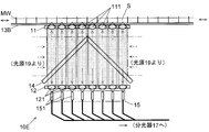
- the multifocal spectroscopic measurement apparatus 10B of the present embodiment irradiates the sample S with irradiation light from the back surface (opposite side of the objective lens array 11) of the multiwell NW using a multiwell NW made of a material transparent with respect to irradiation light.
- the multifocal spectroscopic measurement apparatus 10B has irradiation light output ends 131A arranged in a matrix at the same intervals as the wells in the multiwell NW.
- Each irradiation light output end 131 ⁇ / b> A is an output end of an optical fiber different from that provided in the spectrometer input unit 151, and a light source (not shown) is used so that irradiation light is incident on the input end side of the optical fiber. ) Is provided.
- Each irradiation light output end 131A is embedded in the sample holder 13 so as to be exposed on the upper surface of the sample holder 13A.
- a filter 14B made of a plate-like member arranged perpendicular to the optical axis of the objective lens 111 is provided.
- the filter 14B in this embodiment is not directly irradiated with irradiation light from the light source, but reaches the filter 14B through the well from the irradiation light output end 131A. While removing the irradiation light, the signal light is transmitted.
- the configuration of the multifocal spectroscopic measurement apparatus 10B other than the light source, the irradiation light output end 131A, the sample holder 13A, and the filter 14B described so far is the same as the configuration of the multifocal spectroscopic measurement apparatus 10 of the first embodiment.
- the irradiation light is irradiated to the sample S in the well from the irradiation light output end 131A without passing through the objective lens 111.
- the sample S is irradiated from the irradiation light output end 131A without condensing the irradiation light, but a lens (separate from the objective lens 111) is provided between the irradiation light output end 131A and the well.
- the sample S may be irradiated with irradiation light.
- the signal light generated from each sample S by the irradiation light is collected by the opposing objective lens 111, passes through the filter 14B, and reaches the second lens 121. Thereafter, the operation from the second lens 121 through the spectroscope input unit 151 until the signal light is split by the spectroscope 17 is the same as that of the multifocal spectroscopic measurement apparatus 10 of the first embodiment.
- the multifocal spectroscopic measurement apparatus 10B of the present embodiment directly irradiates irradiation light from the irradiation light output end 131A to the well adjacent thereto using an optical fiber, the irradiation light can be used without waste.
- the filter 14B is provided between the second lens array 12 and the spectroscope input unit 151 instead of being provided between the objective lens array 11 and the second lens array 12. (FIG. 7 (a)).
- the irradiation light from the light source is removed by the filter 14B and is not input to the spectroscope input unit 151.
- the filter 14B is provided between the second lens array 12 and the spectrometer input unit 151, as shown in FIG. 7B, a double-sided lens array 1112 in which the objective lens array and the second lens array are integrated is used. be able to.
- the double-sided lens array 1112 is provided with a plurality of convex portions 1112C on the front and back surfaces of a plate material 1112P transparent to signal light so as to face each other on both sides.
- a plurality of double-sided lenses 1112A obtained by integrating one objective lens 111 and one second lens 121 can be used.
- Multifocal spectroscopic measurement apparatus 10C A multifocal spectroscopic measurement apparatus 10C according to the fourth embodiment will be described with reference to FIG.
- an objective lens array 11A described below is used instead of the objective lens array 11 in the multifocal spectroscopic measurement apparatus 10B of the third embodiment.
- the objective lens array 11A has a plurality of objective lenses 111A arranged in the same manner as the objective lens 111 of the objective lens array 11 in the third embodiment.
- Each objective lens 111A is a lens that collects the signal light from the sample S in the opposite well (observation region) and condenses the signal light on the opposite side of the well.
- a corresponding spectrometer input unit 151 is provided at the position of the focal point. Between the objective lens 111A and the spectroscope input unit 151, a filter 14C that blocks the irradiation light and transmits the signal light is provided, but the second lens is not provided. Except for the points described so far, the multifocal spectroscopic measurement apparatus 10C of the fourth embodiment has the same configuration as the multifocal spectroscopic measurement apparatus 10B of the third embodiment.
- the operation of the multifocal spectroscopic measurement apparatus 10C of the present embodiment is the same as the operation of the multifocal spectroscopic measurement apparatus 10B of the third embodiment, except that the operation of the objective lens 111A and the second lens are not used. is there. According to the multifocal spectroscopic measurement apparatus 10C, the structure can be simplified by not using the second lens.
- the multifocal spectroscopic measurement apparatus 10D of the present embodiment includes a magnification conversion unit 21 including a pair of lenses (condensing units) 211 and 212 between the objective lens array 11 and the sample holder 13A.
- the magnification conversion unit 21 enlarges the image of the signal light from the sample held by the sample holder 13 ⁇ / b> A and introduces it into the objective lens array 11. As a result, a sample having a narrow observation area can be observed.
- the multifocal spectroscopic measurement device 10 ⁇ / b> D includes a pair of lenses (condenser) 221 that reduces the image of the signal light from the objective lens between the second lens array 12 and the spectroscope input unit aggregate 15.
- 222 includes a spectroscope input unit side magnification conversion unit 22.
- the multifocal spectroscopic measurement apparatus 10D may include only one of the magnification conversion unit 21 and the spectroscope input unit side magnification conversion unit 22.
- magnification conversion unit 21 when a sample having a large observation area is used, a magnification conversion unit that reduces an image of signal light from the sample may be used instead of the magnification conversion unit 21. Further, instead of the spectroscope input unit side magnification conversion unit 22, a spectroscope input unit side magnification conversion unit for enlarging the image of the signal light from the objective lens may be used.
- the multifocal spectroscopic measurement apparatus 10E includes a moving unit that moves the sample holder 13B in the left-right direction and the direction perpendicular to the paper surface of FIG.
- the multiwell MW placed on the sample holder 13 ⁇ / b> B has wells sufficiently larger than the number of objective lenses 111 in the objective lens array 11.
- the multifocal spectroscopic measurement apparatus 10E can perform analysis on a larger number of samples by including such a moving unit. By automatically controlling this moving means, high-speed automatic measurement of a large number of samples can be performed.
- the sample holder 13B is moved.
- the objective lens array 11, the second lens array 12, the spectroscope input unit assembly 15, and the filter 14 may be moved together.
- the multifocal spectroscopic measurement device is not limited to the above-described embodiments.
- the objective lens 111 (111A) is provided so as to face the sample S accommodated in the well one by one, but for each of a plurality of observation regions in one sample.
- One objective lens may be provided at a time.
- the second lens and the spectroscope input unit may be provided so as to correspond to each objective lens on a one-to-one basis.
- the multi-well MW having a bottom surface made of a material transparent to the irradiation light and the signal light is used to irradiate the sample S with the irradiation light from the bottom surface side, as shown in FIG.
- the sample S may be irradiated with irradiation light from above the multiwell MW.
- a multiwell MW having an opaque bottom surface can be used.
- the sample S can be irradiated with irradiation light from above the multiwell MW.
- a total of two light sources 19 are used, one for each of the two plate-like members in the filter 14, but the light from one light source 19 is divided into two.
- each of the two plate-like members may be irradiated one by one.
- the cost for manufacturing the filter can be suppressed by increasing the surface accuracy using a filter made of a plate-like member having a small area.
- the same number of plate-like members in the filter may be irradiated one by one.
- the objective lens 111 (111A) is arranged in a matrix that is arranged vertically and horizontally, but may be arranged in a matrix other than the matrix corresponding to the observation region of the sample.
- the objective lenses may be arranged in a triangular lattice shape (FIG. 12) or in a radial manner, may be arranged in disordered positions, and the objective lenses may be arranged in a line.
- the objective lens array 11X in which the objective lenses 111X are arranged in a triangular lattice shape can be used for a multiwell in which many regular hexagonal wells are arranged.
- the objective lens array 11X efficiently irradiates the laser beam of the irradiation light from the light source having a circular cross section to the range. be able to.
- the filter 14 (14A, 14B), the second lens 121, the magnification conversion unit 21, and the spectrometer input unit side are provided between each objective lens 111 (111A) and the corresponding spectrometer input unit 151.
- elements other than the magnification converter 22 are not arranged, it is not excluded from the present invention to arrange an optical system such as a reflecting mirror or a lens at the position.
- the second lens 121 is disposed so as to face the objective lens 111 and the spectroscope input unit 151 is opposed to the second lens 121.
- the spectroscope is disposed.
- the input unit 151 is disposed so as to face the objective lens 111, as described above, when there is an optical system such as a reflecting mirror or a lens between the objective lens 111 (111A) and the spectroscope input unit 151, These relations may not be present.
- the light source 19 that irradiates the sample S with the irradiation light is used.
- the signal light can be obtained without irradiating the sample with the irradiation light as in the case where the signal light is chemiluminescence. Need not use the light source 19.
- FIG. 13 shows a schematic configuration diagram of the spectrometer.
- This spectrometer has a diffraction grating 42.
- FIG. 13A is a view as seen from one direction parallel to the surface of the diffraction grating 42.
- the diffraction grating 42 is provided with grating lines extending in a direction perpendicular to the drawing sheet.
- a pinhole array 41 is provided in which pinholes through which signal light emitted from the second lenses 121 of the second lens array 12 passes are arranged in a matrix.
- the pinhole array 41 corresponds to the spectroscope input unit.
- These two pinholes PH 1 and PH 2 are arranged offset from one another in a direction perpendicular to the plane of FIG.
- These two pinhole PH 1 and the line connecting the PH 2 since the corresponding row of the matrix pinholes are arranged, said row is also parallel to the inclined are (the paper surface to the plane of FIG.
- the wavelength dispersion direction in the diffraction grating 42 is perpendicular to the grating lines, that is, the direction parallel to the drawing sheet. Accordingly, the rows of the matrix are non-parallel to the wavelength dispersion direction in the diffraction grating 42. The same applies to the columns of the matrix.
- a lens 441 is provided between the pinhole array 41 and the diffraction grating 42. Each signal light spreads after passing through the pinhole, and is converted into parallel light by the lens 441 and applied to the diffraction grating 42. On the surface of the diffraction grating 42, the signal light is diffracted at different angles depending on the wavelength. Each diffracted light is condensed on the light receiver 43 by the lens 442.
- FIG. 13 (a) the indicated signal light from the pinhole PH 1 in thin broken lines showed signal light from the pinhole PH 2 a thick broken line.
- the pinhole PH 1 shows those three signal light of diffracted light diffracted by the diffraction grating 42, respectively by a thin broken line.
- These diffracted lights having different wavelengths are incident on the light receiver 43 while being shifted in the direction indicated by the dashed arrows in FIG.
- FIG. 13B shows the state of incidence on the light receiver 43 for diffracted light obtained by diffracting signal light from a large number of pinholes.
- the diffracted light obtained by diffracting the signal light from each pinhole is shifted in the vertical direction in the figure. Lined up.
- each diffracted light extending transversely of the figure by the difference in wavelength Detected.
- the diffracted light beams from different pinholes are detected in a manner that they do not overlap each other because they are individually shifted in the vertical direction while extending in the horizontal direction.
- FIG. 14 shows an image obtained by photographing a plurality of signal lights simultaneously using the spectroscope of FIG. 13 with a CCD camera.
- FIG. 14 (a) the diffracted light DL incident on the light receiver 43 is shown.
- the diffracted light DL within the range indicated by the white line frame in FIG. 14A is enlarged and shown in FIG.
- This image shows that the diffracted light DL is irradiated to different positions in the horizontal direction of the image depending on the wavelength, and the diffracted light DL from each sample is irradiated separately from each other in the vertical direction of the image. It is.
- Each diffracted light DL in FIGS. 14A and 14B has an intensity distribution in the horizontal direction of the figure. When this intensity distribution is graphed, a wavelength spectrum is obtained as shown in FIG. 14 (c).
- the spectroscope of FIG. 13 can also be used in a conventional multipoint simultaneous (multifocal) spectroscopic measurement device such as the devices described in Patent Document 1 and Patent Document 2. In that case, what is necessary is just to make what has arrange
- Conventional multifocal spectroscopic measuring device 92 Microlens array 921 ... Microlens 93 ... Edge filter 94 ... Pinhole array 95 ... Relay lens 96 . Conventional multifocal spectroscopic analyzer objective lens 97 ... lens optical system 98 ... fiber bundle 99 in ... spectrometer DL, DL 1, DL 2 ... intersection PH 1 diffracted light NW ... multiwell P ... signal light of the optical axis with the surface of the diffraction grating, PH 2 ... pinhole S ... sample
Landscapes
- Physics & Mathematics (AREA)
- Spectroscopy & Molecular Physics (AREA)
- General Physics & Mathematics (AREA)
- Health & Medical Sciences (AREA)
- Life Sciences & Earth Sciences (AREA)
- Chemical & Material Sciences (AREA)
- Analytical Chemistry (AREA)
- Biochemistry (AREA)
- General Health & Medical Sciences (AREA)
- Immunology (AREA)
- Pathology (AREA)
- Nuclear Medicine, Radiotherapy & Molecular Imaging (AREA)
- Investigating, Analyzing Materials By Fluorescence Or Luminescence (AREA)
- Investigating Or Analysing Materials By Optical Means (AREA)
Abstract
Description
前記複数の観測領域の各々に光学的に相対する位置に1個ずつ設けられた複数の対物集光部と、
前記複数の対物集光部の各々に対応して1個ずつ設けられた、対応する対物集光部を通過した信号光を前記分光器に入力する分光器入力部と
を備えることを特徴とする。
一方、信号光が化学発光である場合のように、試料に照射光を照射しなくとも信号光が得られる場合には、本発明に係る多焦点分光計測装置に照射光の光源を設ける必要はない。
前記分光器入力部が前記複数の対物集光部の各々に対応して1個ずつ、マトリクスの点に配置されており、
前記マトリクスの行及び列が、前記分光器が有する分光素子における波長の分散方向に対して非平行である
という構成を取ることもできる。分光素子には回折格子やプリズム等を用いることができる。この構成により、1個の分光素子のみを用いて、各信号光からの回折光を互いに重なることなく得ることができる。この分光光学系は、本発明に係る多焦点分光計測装置用光学系だけではなく、例えば特許文献1や特許文献2に記載の装置においても用いることができる。
該装置に装着された状態において前記複数の観測領域の各々に光学的に相対する位置に1個ずつ配置されるように設けられた複数の対物集光部を備えることを特徴とする。
(1-1) 第1実施例の多焦点分光計測装置の構成
第1実施例の多焦点分光計測装置10は、図1に示すように、試料Sを収容するウェルが縦横にマトリクス状に配置されたマルチウェルMWを載置する試料ホルダ13を有する。マルチウェルMWの底面及び試料ホルダ13は、照射光及び信号光に対して透明なガラス製である。この試料ホルダ13に相対して、複数の対物レンズ(対物集光部)111が縦横にマトリクス状に配置された対物レンズアレイ(対物集光部アレイ)11が設けられている。これら複数の対物レンズ111は、試料ホルダ13にマルチウェルMWが保持された状態において、各ウェルに1個ずつ相対するように設けられている。これらウェルはそれぞれ、1つの試料Sの観測領域となる。各対物レンズ111は、試料ホルダ13の反対側から、信号光である平行光が入射したときに、試料ホルダ13に保持されたマルチウェルMWにおいて相対するウェル内で焦点を結ぶ位置に配置されている。
第1実施例の多焦点分光計測装置10の動作を説明する。
マルチウェルMWの各ウェルに試料Sを収容し、このマルチウェルMWを試料ホルダ13に保持する。この状態で、2個の光源19よりそれぞれ、径拡大光学系191を通して、対応するフィルタ14の板状部材の全面に照射光(レーザ光)を照射する。照射光は図中の光路上において破線の矢印で示す。照射光はフィルタ14によって、対物レンズ111の光軸に平行な方向に反射され、全ての対物レンズ111に入射する。照射光は、各対物レンズ111において、相対するウェル(観測領域)に集光され、それにより試料Sに照射される。
第1実施例の多焦点分光計測装置10を用いて、蛍光及びラマン光を計測する実験を行った。この実験では、マルチウェルMW内の縦に8個、横に12個並んだ合計96個のウェルを測定領域とした。対物レンズ111、第2レンズ121及び分光器入力部151も同様に縦に8個、横に12個配置した。試料Sは、蛍光計測ではローダミン6G、ラマン光計測ではエタノールであり、各計測においては96個の全ウェルに同種の試料を収容した。このように、この実験において試料を収容したウェルはマルチウェルMW全体の一部のみであるが、それでもなお、96個の観測領域を合わせた全観測領域は縦36.0mm、横54.0mmという、特許文献1における全観測領域の約107倍の面積を有する。
図5を用いて、第2実施例の多焦点分光計測装置10Aについて説明する。この多焦点分光計測装置10Aは、第1実施例の多焦点分光計測装置10におけるフィルタ14の代わりに、1枚の四角形の板状部材から成るフィルタ14Aが、全ての対物レンズ111を覆うように、対物レンズ111の光軸に対して45°傾斜して設けられている。光源19は1個のみ用いられる。光源19からのレーザ光は、フィルタ14Aの、対物レンズアレイ11を向いた面の全面に照射され、フィルタ14Aにより反射されて各対物レンズ111に入射する。このフィルタ14Aを除いて、第2実施例の多焦点分光計測装置10Aの構成及び動作は、第1実施例の多焦点分光計測装置10の構成及び動作と同様である。
図6を用いて、第3実施例の多焦点分光計測装置10Bについて説明する。本実施例の多焦点分光計測装置10Bは、照射光に関して透明な材料から成るマルチウェルNWを用いて、マルチウェルNWの背面(対物レンズアレイ11の反対側)から照射光を試料Sに照射するための構成を有する。多焦点分光計測装置10Bは、マルチウェルNWにおけるウェルと同じ間隔でマトリクス状に配置された照射光出力端131Aを有している。各照射光出力端131Aは、分光器入力部151に設けられたものとは別の光ファイバの出力端であり、当該光ファイバの入力端側に照射光が入射するように光源(図示せず)が設けられている。各照射光出力端131Aは、試料ホルダ13Aの上面に露出するように、試料ホルダ13に埋め込まれている。
図8を用いて、第4実施例の多焦点分光計測装置10Cについて説明する。本実施例の多焦点分光計測装置10Cでは、第3実施例の多焦点分光計測装置10Bにおける対物レンズアレイ11の代わりに、以下に述べる対物レンズアレイ11Aを用いる。対物レンズアレイ11Aは、第3実施例における対物レンズアレイ11の対物レンズ111と同様に配置された複数の対物レンズ111Aを有する。各対物レンズ111Aは、相対するウェル(観測領域)内の試料Sからの信号光を収集し、ウェルの反対側において当該信号光を焦点に集光するレンズである。この焦点の位置に、対応する分光器入力部151が設けられている。対物レンズ111Aと分光器入力部151の間には、照射光を遮断して信号光を透過させるフィルタ14Cが設けられているが、第2レンズは設けられていない。ここまでに述べた点以外は、第4実施例の多焦点分光計測装置10Cは第3実施例の多焦点分光計測装置10Bと同様の構成を有する。
図9を用いて、第5実施例の多焦点分光計測装置を示す。本実施例の多焦点分光計測装置10Dは、対物レンズアレイ11と試料ホルダ13Aの間に、2枚1組のレンズ(集光部)211、212から成る倍率変換部21を有する。倍率変換部21は、試料ホルダ13Aに保持された試料からの信号光の像を拡大して対物レンズアレイ11に導入する。これにより、観測領域が狭い試料を観測することができる。また、多焦点分光計測装置10Dは、第2レンズアレイ12と分光器入力部集合体15の間に、対物レンズからの信号光の像を縮小する2枚1組のレンズ(集光部)221、222から成る分光器入力部側倍率変換部22を有する。これにより、光ファイバの入力端である分光器入力部151よりも対物レンズアレイ及び第2レンズを大きくすることができる。なお、多焦点分光計測装置10Dは、倍率変換部21と分光器入力部側倍率変換部22のいずれか一方のみを有していてもよい。また、観測領域が大きい試料を用いる場合には、前記倍率変換部21の代わりに、試料からの信号光の像を縮小する倍率変換部を用いてもよい。また、前記分光器入力部側倍率変換部22の代わりに、対物レンズからの信号光の像を拡大する分光器入力部側倍率変換部を用いてもよい。
図10を用いて、第6実施例の多焦点分光計測装置を示す。本実施例の多焦点分光計測装置10Eは、試料ホルダ13Bを図10の左右方向及び紙面に垂直な方向に移動する移動手段を有している。試料ホルダ13Bに載置されるマルチウェルMWは、対物レンズアレイ11における対物レンズ111の個数よりも十分に多いウェルを有している。多焦点分光計測装置10Eは、このような移動手段を有することにより、より多くの試料に対する分析を行うことができる。この移動手段を自動制御することにより、多数試料の高速自動測定を行うことができる。また、マルチウェルMWの代わりに、試料ホルダ13Bに大型の試料を保持させることにより、当該試料の分光イメージング測定を行うことができる。なお、多焦点分光計測装置10Eでは試料ホルダ13Bを移動するが、対物レンズアレイ11、第2レンズアレイ12、分光器入力部集合体15及びフィルタ14を一体として移動するようにしてもよい。
本発明に係る多焦点分光計測装置は、上記実施例には限定されない。
例えば、上記実施例ではいずれも、ウェルに収容された試料Sに対して1個ずつ相対するように対物レンズ111(111A)を設けたが、1個の試料における複数の観測領域の各々に対して1個ずつ対物レンズを設けるようにしてもよい。この場合、第2レンズ及び分光器入力部は、各対物レンズに1対1に対応するように設ければよい。
上記各実施例では、分光器は、特許文献1と同様のものを用いるが、以下では、それ以外の分光器の構成の例を示す。図13に、当該分光器の概略構成図を示す。この分光器は回折格子42を有する。図13(a)は回折格子42の表面に平行な1方向から見た図である。回折格子42には、図の紙面に垂直な方向に延びる格子線が設けられている。回折格子42の前段には、第2レンズアレイ12の各第2レンズ121から出射された信号光が通過するピンホールがマトリクス状に配置されたピンホールアレイ41が設けられている。ピンホールアレイ41は前記分光器入力部に相当する。図13(a)には、図13(a)に実線の矢印で示した方向に隣接する2個のピンホールPH1及びPH2を示した。これら2個のピンホールPH1及びPH2は、図の紙面に垂直な方向に互いにずれて配置されている。これら2個のピンホールPH1とPH2を結ぶ線は、ピンホールが配置されるマトリクスの行に相当することから、該行は図の紙面に対して傾斜している(該紙面に平行でも垂直でもない)。それに対して、回折格子42における波長の分散方向は格子線に垂直、すなわち図の紙面に平行な方向である。従って、マトリクスの行は、回折格子42における波長の分散方向に対して非平行である。マトリクスの列も同様である。ピンホールアレイ41と回折格子42の間にはレンズ441が設けられている。各信号光はピンホールを通過した後に拡がってゆき、レンズ441により平行光となって回折格子42に照射される。回折格子42の表面では、信号光は波長により異なる角度で回折される。各回折光は、レンズ442により受光器43に集光される。
11、11A、11P、11X…対物レンズアレイ(対物集光部アレイ)
111、111A、111X…対物レンズ(対物集光部)
111C、1112C…レンズアレイの凸部
1112P、112…レンズアレイの板材
1112…両面レンズアレイ
1112A…両面レンズ
12…第2レンズアレイ(分光器側レンズアレイ、分光器側集光部アレイ)
121…第2レンズ(分光器側レンズ、分光器側集光部)
13、13A、13B…試料ホルダ(試料配置部)
131A…照射光出力端
14、14A、14B、14C…フィルタ
15…分光器入力部集合体
151…分光器入力部
17…分光器
19、91…レーザ光源
191…径拡大光学系
1911…径拡大レンズ
1912…平行ビーム形成レンズ
21…倍率変換部
211…倍率変換部のレンズ(集光部)
22…分光器入力部側倍率変換部
221…分光器入力部側倍率変換部のレンズ(集光部)
41…ピンホールアレイ(分光器入力部)
42…回折格子
43…受光器
441、442…レンズ
90…従来の多焦点分光計測装置
92…マイクロレンズアレイ
921…マイクロレンズ
93…エッジフィルタ
94…ピンホールアレイ
95…リレーレンズ
96…従来の多焦点分光計測装置における対物レンズ
97…レンズ光学系
98…ファイババンドル
99…分光器
DL、DL1、DL2…回折光
NW…マルチウェル
P…信号光の光軸と回折格子の表面の交点
PH1、PH2…ピンホール
S…試料
Claims (16)
- 試料配置部に配置された試料における所定の複数の観測領域から発せられる信号光を分光器に導入することにより分光する装置であって、
前記複数の観測領域の各々に光学的に相対する位置に1個ずつ設けられた複数の対物集光部と、
前記複数の対物集光部の各々に対応して1個ずつ設けられた、対応する対物集光部を通過した信号光を前記分光器に入力する分光器入力部と
を備えることを特徴とする多焦点分光計測装置。 - 前記複数の対物集光部のうちの一部又は全部において、対応する前記分光器入力部との間に分光器側集光部を備え、該対物集光部と該分光器側集光部の間の信号光が該対物集光部を通過して焦点を結ぶ位置に、該対物集光部と光学的に相対する前記観測領域内の点が存在し、該信号光が該分光器側集光部を通過して焦点を結ぶ位置に、該対物集光部に対応する分光器入力部が存在することを特徴とする請求項1に記載の多焦点分光計測装置。
- 前記試料に照射することによって前記試料から前記信号光が発せられる光である照射光を該試料に照射する光源を備えることを特徴とする請求項1又は2に記載の多焦点分光計測装置。
- 前記光源が、前記対物集光部を通して前記照射光を前記試料に照射する位置に配置されていることを特徴とする請求項3に記載の多焦点分光計測装置。
- 前記試料配置部と前記分光器入力部の間に設けられた、前記信号光の波長の光を透過して前記照射光の波長の光を反射するフィルタを備えることを特徴とする請求項4に記載の多焦点分光計測装置。
- 前記フィルタに複数の照射光が照射され、該フィルタに反射された後の複数の照射光が互いに異なる対物集光部に照射されるように該フィルタが配置されていることを特徴とする請求項5に記載の多焦点分光計測装置。
- 前記フィルタが前記対物集光部と前記分光器入力部の間に、前記光源から照射される照射光が前記対物集光部の光軸の方向に反射するように配置されていることを特徴とする請求項5又は6に記載の多焦点分光計測装置。
- 前記光源が、前記対物集光部を通すことなく前記照射光を前記試料に照射する位置に配置されていることを特徴とする請求項3に記載の多焦点分光計測装置。
- 前記試料配置部と前記分光器入力部の間に設けられた、前記信号光の波長の光を透過して前記照射光の波長の光を除去するフィルタを備えることを特徴とする請求項8に記載の多焦点分光計測装置。
- 前記複数の対物集光部が縦横にマトリクス状に配置されている対物集光部アレイを備えることを特徴とする請求項1~8のいずれかに記載の多焦点分光計測装置。
- 前記対物集光部アレイと前記分光器入力部の間に、前記複数の対物集光部の各々に光学的に相対して分光器側集光部が1個ずつ設けられた分光器側集光部アレイを備え、各々の前記対物集光部と該対物集光部に光学的に相対する前記分光器側集光部の間の信号光が該対物集光部を通過して焦点を結ぶ位置に、該対物集光部と光学的に相対する前記観測領域内の点が存在し、該信号光が該分光器側集光部を通過して焦点を結ぶ位置に、該対物集光部に対応する分光器入力部が存在することを特徴とする請求項10に記載の多焦点分光計測装置。
- 前記複数の観測領域と前記複数の対物集光部の間に、該複数の観測領域の各々からの信号光の像を拡大又は縮小する倍率変換部を備えることを特徴とする請求項1~11のいずれかに記載の多焦点分光計測装置。
- 前記複数の対物集光部と前記分光器入力部の間に、該複数の対物集光部の各々からの信号光の像を拡大又は縮小する分光器入力部側倍率変換部を備えることを特徴とする請求項1~12のいずれかに記載の多焦点分光計測装置。
- 前記分光器入力部が前記複数の対物集光部の各々に対応して1個ずつ、マトリクスの点に配置されており、
前記マトリクスの行及び列が、前記分光器が有する分光素子における波長の分散方向に対して非平行である
ことを特徴とする請求項1~13のいずれかに記載の多焦点分光計測装置。 - 前記試料配置部に配置された試料を含む平面に沿って該試料と前記複数の対物集光部の相対的な位置を移動させる移動手段を備えることを特徴とする請求項1~14のいずれかに記載の多焦点分光計測装置。
- 試料配置部に配置された試料における所定の複数の観測領域から発せられる信号光を分光器に導入することにより分光する装置で用いられる光学系であって、
該装置に装着された状態において前記複数の観測領域の各々に光学的に相対する位置に1個ずつ配置されるように設けられた複数の対物集光部を備えることを特徴とする多焦点分光計測装置用光学系。
Priority Applications (4)
| Application Number | Priority Date | Filing Date | Title |
|---|---|---|---|
| JP2016572194A JP6622723B2 (ja) | 2015-01-30 | 2016-01-29 | 多焦点分光計測装置、及び多焦点分光計測装置用光学系 |
| CA2988822A CA2988822C (en) | 2015-01-30 | 2016-01-29 | Multifocal spectrometric measurement device and optical system for multifocal spectrometric measurement device |
| EP16743549.4A EP3273225B1 (en) | 2015-01-30 | 2016-01-29 | Multifocal spectroscopic measurement device, and optical system for multifocal spectroscopic measurement device |
| US15/547,652 US10823612B2 (en) | 2015-01-30 | 2016-01-29 | Multifocal spectrometric measurement device, and optical system for multifocal spectrometric measurement device |
Applications Claiming Priority (2)
| Application Number | Priority Date | Filing Date | Title |
|---|---|---|---|
| JP2015017431 | 2015-01-30 | ||
| JP2015-017431 | 2015-01-30 |
Publications (1)
| Publication Number | Publication Date |
|---|---|
| WO2016121946A1 true WO2016121946A1 (ja) | 2016-08-04 |
Family
ID=56543548
Family Applications (1)
| Application Number | Title | Priority Date | Filing Date |
|---|---|---|---|
| PCT/JP2016/052707 WO2016121946A1 (ja) | 2015-01-30 | 2016-01-29 | 多焦点分光計測装置、及び多焦点分光計測装置用光学系 |
Country Status (5)
| Country | Link |
|---|---|
| US (1) | US10823612B2 (ja) |
| EP (1) | EP3273225B1 (ja) |
| JP (1) | JP6622723B2 (ja) |
| CA (1) | CA2988822C (ja) |
| WO (1) | WO2016121946A1 (ja) |
Cited By (4)
| Publication number | Priority date | Publication date | Assignee | Title |
|---|---|---|---|---|
| CN110192090A (zh) * | 2017-01-19 | 2019-08-30 | 安捷伦科技有限公司 | 用于多光束光学分析的光谱仪模块、系统及方法 |
| JP2021520496A (ja) * | 2018-04-13 | 2021-08-19 | アプライド マテリアルズ インコーポレイテッドApplied Materials,Incorporated | 光ルミネセンス分光法を用いた有機発光ダイオード製造のための計測学 |
| JPWO2021261035A1 (ja) * | 2020-06-24 | 2021-12-30 | ||
| WO2022137959A1 (ja) * | 2020-12-22 | 2022-06-30 | 国立大学法人大阪大学 | 光学モジュール、及び多焦点光学装置 |
Families Citing this family (2)
| Publication number | Priority date | Publication date | Assignee | Title |
|---|---|---|---|---|
| US10852519B2 (en) * | 2016-11-30 | 2020-12-01 | Asm Technology Singapore Pte Ltd | Confocal imaging of an object utilising a pinhole array |
| CN113640257A (zh) * | 2020-04-27 | 2021-11-12 | 中国科学院上海硅酸盐研究所 | 阵列样品光谱测试系统 |
Citations (10)
| Publication number | Priority date | Publication date | Assignee | Title |
|---|---|---|---|---|
| JP2002514739A (ja) * | 1997-10-31 | 2002-05-21 | カール・ツアイス・シュティフテュング・ハンデルンド・アルス・カール・ツアイス | 光学的アレイシステムおよびマイクロタイタープレート用読み取り器 |
| US20050264776A1 (en) * | 1994-07-15 | 2005-12-01 | Baer Stephen C | Superresolution in microlithography and fluorescence microscopy |
| US7170597B1 (en) * | 1999-06-26 | 2007-01-30 | Packard Instrument Company, Inc. | Microplate reader |
| JP2009517662A (ja) * | 2005-11-23 | 2009-04-30 | イルミナ インコーポレイテッド | 共焦点イメージング方法および装置 |
| JP2010151801A (ja) * | 2008-11-18 | 2010-07-08 | St Japan Inc | ラマンイメージング装置 |
| US20100324834A1 (en) * | 2007-08-29 | 2010-12-23 | Eppendorf Ag | Device and Method for Radiometric Measurement of a Plurality of Samples |
| JP2011525629A (ja) * | 2008-06-24 | 2011-09-22 | コーニンクレッカ フィリップス エレクトロニクス エヌ ヴィ | マイクロアレイ評価システム及び方法 |
| JP2012229922A (ja) * | 2011-04-25 | 2012-11-22 | Ricoh Co Ltd | 分光計測装置、画像評価装置、及び画像形成装置 |
| JP2012237647A (ja) * | 2011-05-11 | 2012-12-06 | Univ Of Tokyo | 多焦点共焦点ラマン分光顕微鏡 |
| JP2013522629A (ja) * | 2010-03-15 | 2013-06-13 | バイオ−ラド ラボラトリーズ インコーポレイテッド | 超小型組立てイメージング・フロー・サイトメータ |
Family Cites Families (8)
| Publication number | Priority date | Publication date | Assignee | Title |
|---|---|---|---|---|
| US5866911A (en) | 1994-07-15 | 1999-02-02 | Baer; Stephen C. | Method and apparatus for improving resolution in scanned optical system |
| US6104945A (en) | 1995-08-01 | 2000-08-15 | Medispectra, Inc. | Spectral volume microprobe arrays |
| US6563581B1 (en) | 2000-07-14 | 2003-05-13 | Applera Corporation | Scanning system and method for scanning a plurality of samples |
| WO2004090505A2 (en) | 2003-04-04 | 2004-10-21 | Vp Holding, Llc | Method and apparatus for enhanced nano-spectroscopic scanning |
| KR100527535B1 (ko) | 2003-04-17 | 2005-11-09 | 주식회사 하이닉스반도체 | 입출력 압축 회로 |
| EP2163885A1 (en) | 2008-06-24 | 2010-03-17 | Koninklijke Philips Electronics N.V. | Microarray characterization system and method |
| JP5229201B2 (ja) | 2009-12-07 | 2013-07-03 | 三菱電機株式会社 | プラスチックの識別装置およびその方法 |
| US9229169B2 (en) * | 2011-08-16 | 2016-01-05 | International Business Machines Corporation | Lens array optical coupling to photonic chip |
-
2016
- 2016-01-29 US US15/547,652 patent/US10823612B2/en active Active
- 2016-01-29 JP JP2016572194A patent/JP6622723B2/ja active Active
- 2016-01-29 WO PCT/JP2016/052707 patent/WO2016121946A1/ja active Application Filing
- 2016-01-29 CA CA2988822A patent/CA2988822C/en active Active
- 2016-01-29 EP EP16743549.4A patent/EP3273225B1/en active Active
Patent Citations (10)
| Publication number | Priority date | Publication date | Assignee | Title |
|---|---|---|---|---|
| US20050264776A1 (en) * | 1994-07-15 | 2005-12-01 | Baer Stephen C | Superresolution in microlithography and fluorescence microscopy |
| JP2002514739A (ja) * | 1997-10-31 | 2002-05-21 | カール・ツアイス・シュティフテュング・ハンデルンド・アルス・カール・ツアイス | 光学的アレイシステムおよびマイクロタイタープレート用読み取り器 |
| US7170597B1 (en) * | 1999-06-26 | 2007-01-30 | Packard Instrument Company, Inc. | Microplate reader |
| JP2009517662A (ja) * | 2005-11-23 | 2009-04-30 | イルミナ インコーポレイテッド | 共焦点イメージング方法および装置 |
| US20100324834A1 (en) * | 2007-08-29 | 2010-12-23 | Eppendorf Ag | Device and Method for Radiometric Measurement of a Plurality of Samples |
| JP2011525629A (ja) * | 2008-06-24 | 2011-09-22 | コーニンクレッカ フィリップス エレクトロニクス エヌ ヴィ | マイクロアレイ評価システム及び方法 |
| JP2010151801A (ja) * | 2008-11-18 | 2010-07-08 | St Japan Inc | ラマンイメージング装置 |
| JP2013522629A (ja) * | 2010-03-15 | 2013-06-13 | バイオ−ラド ラボラトリーズ インコーポレイテッド | 超小型組立てイメージング・フロー・サイトメータ |
| JP2012229922A (ja) * | 2011-04-25 | 2012-11-22 | Ricoh Co Ltd | 分光計測装置、画像評価装置、及び画像形成装置 |
| JP2012237647A (ja) * | 2011-05-11 | 2012-12-06 | Univ Of Tokyo | 多焦点共焦点ラマン分光顕微鏡 |
Non-Patent Citations (1)
| Title |
|---|
| See also references of EP3273225A4 * |
Cited By (16)
| Publication number | Priority date | Publication date | Assignee | Title |
|---|---|---|---|---|
| JP2020505595A (ja) * | 2017-01-19 | 2020-02-20 | アジレント・テクノロジーズ・インクAgilent Technologies, Inc. | 複数の光ビームを用いた光学分析のための光学分光計モジュール、システム、及び方法 |
| CN110192090A (zh) * | 2017-01-19 | 2019-08-30 | 安捷伦科技有限公司 | 用于多光束光学分析的光谱仪模块、系统及方法 |
| US11703388B2 (en) | 2017-01-19 | 2023-07-18 | Agilent Technologies, Inc. | Optical spectrometer modules, systems and methods for optical analysis with multiple light beams |
| JP7142013B2 (ja) | 2017-01-19 | 2022-09-26 | アジレント・テクノロジーズ・インク | 複数の光ビームを用いた光学分析のための光学分光計モジュール、システム、及び方法 |
| US11662317B2 (en) | 2018-04-13 | 2023-05-30 | Applied Materials, Inc. | Metrology for OLED manufacturing using photoluminescence spectroscopy |
| JP2021520496A (ja) * | 2018-04-13 | 2021-08-19 | アプライド マテリアルズ インコーポレイテッドApplied Materials,Incorporated | 光ルミネセンス分光法を用いた有機発光ダイオード製造のための計測学 |
| JP7556006B2 (ja) | 2018-04-13 | 2024-09-25 | アプライド マテリアルズ インコーポレイテッド | 光ルミネセンス分光法を用いた有機発光ダイオード製造のための計測学 |
| US11927535B2 (en) | 2018-04-13 | 2024-03-12 | Applied Materials, Inc. | Metrology for OLED manufacturing using photoluminescence spectroscopy |
| JP7158494B2 (ja) | 2018-04-13 | 2022-10-21 | アプライド マテリアルズ インコーポレイテッド | 光ルミネセンス分光法を用いた有機発光ダイオード製造のための計測学 |
| JP2023015045A (ja) * | 2018-04-13 | 2023-01-31 | アプライド マテリアルズ インコーポレイテッド | 光ルミネセンス分光法を用いた有機発光ダイオード製造のための計測学 |
| WO2021261035A1 (ja) * | 2020-06-24 | 2021-12-30 | 株式会社島津製作所 | 顕微ラマン分光測定装置、及び顕微ラマン分光測定装置の調整方法 |
| JP7392856B2 (ja) | 2020-06-24 | 2023-12-06 | 株式会社島津製作所 | 顕微ラマン分光測定装置、及び顕微ラマン分光測定装置の調整方法 |
| JPWO2021261035A1 (ja) * | 2020-06-24 | 2021-12-30 | ||
| JPWO2022137959A1 (ja) * | 2020-12-22 | 2022-06-30 | ||
| WO2022137959A1 (ja) * | 2020-12-22 | 2022-06-30 | 国立大学法人大阪大学 | 光学モジュール、及び多焦点光学装置 |
| JP7455434B2 (ja) | 2020-12-22 | 2024-03-26 | 国立大学法人大阪大学 | 光学モジュール、及び多焦点光学装置 |
Also Published As
| Publication number | Publication date |
|---|---|
| JPWO2016121946A1 (ja) | 2017-11-24 |
| JP6622723B2 (ja) | 2019-12-18 |
| US10823612B2 (en) | 2020-11-03 |
| EP3273225B1 (en) | 2022-11-23 |
| CA2988822A1 (en) | 2016-08-04 |
| EP3273225A1 (en) | 2018-01-24 |
| CA2988822C (en) | 2022-06-28 |
| EP3273225A4 (en) | 2019-01-09 |
| US20180136040A1 (en) | 2018-05-17 |
Similar Documents
| Publication | Publication Date | Title |
|---|---|---|
| JP6622723B2 (ja) | 多焦点分光計測装置、及び多焦点分光計測装置用光学系 | |
| JP4887989B2 (ja) | 光学顕微鏡及びスペクトル測定方法 | |
| JP6091100B2 (ja) | 共焦点顕微装置 | |
| JP2012237647A (ja) | 多焦点共焦点ラマン分光顕微鏡 | |
| JP2014010216A (ja) | 多焦点共焦点顕微鏡 | |
| JP4817356B2 (ja) | 光学顕微鏡 | |
| EP2685303B1 (en) | Optical microscope, and spectroscopic measurement method | |
| US8633432B2 (en) | Reflective focusing and transmissive projection device | |
| KR20160132936A (ko) | 광학 간섭 장치 | |
| US10156522B2 (en) | Parallel acquisition of spectral signals from a 2-D laser beam array | |
| US20160054225A1 (en) | Ultra dark field microscope | |
| US20130250088A1 (en) | Multi-color confocal microscope and imaging methods | |
| US20110147613A1 (en) | Device and method for enhanced analysis of particle sample | |
| KR101632672B1 (ko) | 공초점 분광 현미경 | |
| JP7325736B2 (ja) | 光学測定装置 | |
| Balsam et al. | Modeling and design of micromachined optical Söller collimators for lensless CCD-based fluorometry | |
| KR20150146074A (ko) | 멀티모달 현미경 | |
| EP3236303A1 (en) | Confocal microscope with improved resolution | |
| CN216208595U (zh) | 双波长光源拉曼光谱仪系统 | |
| KR101861919B1 (ko) | 반도체의 고속 광학 검사방법 | |
| JP2009230021A (ja) | 光学顕微鏡、及びスペクトル測定方法 | |
| CN210571973U (zh) | 一种带有光镊的显微拉曼系统 | |
| CN113899728A (zh) | 双波长光源拉曼光谱仪系统 | |
| JP5787151B2 (ja) | 分光ユニット及び走査型顕微鏡 | |
| US7817275B2 (en) | Scanning optical microscope with long working distance objective |
Legal Events
| Date | Code | Title | Description |
|---|---|---|---|
| 121 | Ep: the epo has been informed by wipo that ep was designated in this application |
Ref document number: 16743549 Country of ref document: EP Kind code of ref document: A1 |
|
| DPE1 | Request for preliminary examination filed after expiration of 19th month from priority date (pct application filed from 20040101) | ||
| ENP | Entry into the national phase |
Ref document number: 2016572194 Country of ref document: JP Kind code of ref document: A |
|
| NENP | Non-entry into the national phase |
Ref country code: DE |
|
| REEP | Request for entry into the european phase |
Ref document number: 2016743549 Country of ref document: EP |
|
| ENP | Entry into the national phase |
Ref document number: 2988822 Country of ref document: CA |
|
| WWE | Wipo information: entry into national phase |
Ref document number: 15547652 Country of ref document: US |