WO2016121325A1 - 非水電解質二次電池用負極活物質及び非水電解質二次電池 - Google Patents
非水電解質二次電池用負極活物質及び非水電解質二次電池 Download PDFInfo
- Publication number
- WO2016121325A1 WO2016121325A1 PCT/JP2016/000221 JP2016000221W WO2016121325A1 WO 2016121325 A1 WO2016121325 A1 WO 2016121325A1 JP 2016000221 W JP2016000221 W JP 2016000221W WO 2016121325 A1 WO2016121325 A1 WO 2016121325A1
- Authority
- WO
- WIPO (PCT)
- Prior art keywords
- negative electrode
- active material
- electrode active
- electrolyte secondary
- sio
- Prior art date
- Legal status (The legal status is an assumption and is not a legal conclusion. Google has not performed a legal analysis and makes no representation as to the accuracy of the status listed.)
- Ceased
Links
Images


Classifications
-
- H—ELECTRICITY
- H01—ELECTRIC ELEMENTS
- H01M—PROCESSES OR MEANS, e.g. BATTERIES, FOR THE DIRECT CONVERSION OF CHEMICAL ENERGY INTO ELECTRICAL ENERGY
- H01M4/00—Electrodes
- H01M4/02—Electrodes composed of, or comprising, active material
- H01M4/36—Selection of substances as active materials, active masses, active liquids
- H01M4/362—Composites
- H01M4/364—Composites as mixtures
-
- H—ELECTRICITY
- H01—ELECTRIC ELEMENTS
- H01M—PROCESSES OR MEANS, e.g. BATTERIES, FOR THE DIRECT CONVERSION OF CHEMICAL ENERGY INTO ELECTRICAL ENERGY
- H01M4/00—Electrodes
- H01M4/02—Electrodes composed of, or comprising, active material
- H01M4/13—Electrodes for accumulators with non-aqueous electrolyte, e.g. for lithium-accumulators; Processes of manufacture thereof
-
- H—ELECTRICITY
- H01—ELECTRIC ELEMENTS
- H01M—PROCESSES OR MEANS, e.g. BATTERIES, FOR THE DIRECT CONVERSION OF CHEMICAL ENERGY INTO ELECTRICAL ENERGY
- H01M4/00—Electrodes
- H01M4/02—Electrodes composed of, or comprising, active material
- H01M4/36—Selection of substances as active materials, active masses, active liquids
- H01M4/362—Composites
- H01M4/366—Composites as layered products
-
- H—ELECTRICITY
- H01—ELECTRIC ELEMENTS
- H01M—PROCESSES OR MEANS, e.g. BATTERIES, FOR THE DIRECT CONVERSION OF CHEMICAL ENERGY INTO ELECTRICAL ENERGY
- H01M4/00—Electrodes
- H01M4/02—Electrodes composed of, or comprising, active material
- H01M4/36—Selection of substances as active materials, active masses, active liquids
- H01M4/38—Selection of substances as active materials, active masses, active liquids of elements or alloys
- H01M4/386—Silicon or alloys based on silicon
-
- H—ELECTRICITY
- H01—ELECTRIC ELEMENTS
- H01M—PROCESSES OR MEANS, e.g. BATTERIES, FOR THE DIRECT CONVERSION OF CHEMICAL ENERGY INTO ELECTRICAL ENERGY
- H01M4/00—Electrodes
- H01M4/02—Electrodes composed of, or comprising, active material
- H01M4/36—Selection of substances as active materials, active masses, active liquids
- H01M4/58—Selection of substances as active materials, active masses, active liquids of inorganic compounds other than oxides or hydroxides, e.g. sulfides, selenides, tellurides, halogenides or LiCoFy; of polyanionic structures, e.g. phosphates, silicates or borates
- H01M4/5825—Oxygenated metallic salts or polyanionic structures, e.g. borates, phosphates, silicates, olivines
-
- H—ELECTRICITY
- H01—ELECTRIC ELEMENTS
- H01M—PROCESSES OR MEANS, e.g. BATTERIES, FOR THE DIRECT CONVERSION OF CHEMICAL ENERGY INTO ELECTRICAL ENERGY
- H01M4/00—Electrodes
- H01M4/02—Electrodes composed of, or comprising, active material
- H01M4/62—Selection of inactive substances as ingredients for active masses, e.g. binders, fillers
- H01M4/624—Electric conductive fillers
- H01M4/625—Carbon or graphite
-
- H—ELECTRICITY
- H01—ELECTRIC ELEMENTS
- H01M—PROCESSES OR MEANS, e.g. BATTERIES, FOR THE DIRECT CONVERSION OF CHEMICAL ENERGY INTO ELECTRICAL ENERGY
- H01M4/00—Electrodes
- H01M4/02—Electrodes composed of, or comprising, active material
- H01M2004/026—Electrodes composed of, or comprising, active material characterised by the polarity
- H01M2004/027—Negative electrodes
-
- Y—GENERAL TAGGING OF NEW TECHNOLOGICAL DEVELOPMENTS; GENERAL TAGGING OF CROSS-SECTIONAL TECHNOLOGIES SPANNING OVER SEVERAL SECTIONS OF THE IPC; TECHNICAL SUBJECTS COVERED BY FORMER USPC CROSS-REFERENCE ART COLLECTIONS [XRACs] AND DIGESTS
- Y02—TECHNOLOGIES OR APPLICATIONS FOR MITIGATION OR ADAPTATION AGAINST CLIMATE CHANGE
- Y02E—REDUCTION OF GREENHOUSE GAS [GHG] EMISSIONS, RELATED TO ENERGY GENERATION, TRANSMISSION OR DISTRIBUTION
- Y02E60/00—Enabling technologies; Technologies with a potential or indirect contribution to GHG emissions mitigation
- Y02E60/10—Energy storage using batteries
Definitions
- the present disclosure relates to a negative electrode active material for a non-aqueous electrolyte secondary battery and a non-aqueous electrolyte secondary battery.
- Patent Document 1 discloses a nonaqueous electrolyte secondary battery in which SiO x is mixed with graphite to form a negative electrode active material.
- the non-aqueous electrolyte secondary battery using SiO x as the negative electrode active material has a problem that the initial charge / discharge efficiency is lower than when graphite is used as the negative electrode active material. This is mainly due to the change of SiO x to Li 4 SiO 4 (irreversible reactant) due to the irreversible reaction during charging and discharging. Accordingly, a negative electrode active material represented by SiLi x O y (0 ⁇ x ⁇ 1.0, 0 ⁇ y ⁇ 1.5) has been proposed in order to suppress the irreversible reaction and improve the initial charge / discharge efficiency. (See Patent Document 2).
- Patent Document 3 discloses a negative electrode active material in which a lithium silicate phase mainly composed of Li 4 SiO 4 is contained in silicon oxide.
- initial charge / discharge is performed by heat-treating a mixture of SiO x and a lithium compound at a high temperature to convert SiO 2 into Li 4 SiO 4 which is an irreversible reactant. Improving efficiency.
- SiO 2 remains inside the particle, and Li 4 SiO 4 is generated only on the particle surface.
- the crystal grain size in this case Si and Li 4 SiO 4 is assumed to be increased. The increase in the crystal grain size increases the volume change of the active material particles due to charge / discharge, for example, and decreases the lithium ion conductivity.
- non-aqueous electrolyte secondary batteries are required not only to have high initial charge / discharge efficiency, but also to suppress a decrease in capacity due to charge / discharge cycles.
- An object of the present disclosure is a negative electrode active material for a non-aqueous electrolyte secondary battery including a silicon material, which has a high initial charge / discharge efficiency and is capable of constructing a non-aqueous electrolyte secondary battery excellent in cycle characteristics. It is to provide an active material.
- a negative electrode active material for a nonaqueous electrolyte secondary battery which is one embodiment of the present disclosure, is dispersed in a lithium silicate phase represented by Li 2z SiO (2 + z) ⁇ 0 ⁇ z ⁇ 2 ⁇ and a lithium silicate phase.
- the symmetry obtained by image analysis of the reflected electron image of the cross section of the mother particle is 1.5 or less, where symmetry is the 256th floor for each pixel of the reflected electron image. This is a value (b / a) obtained by dividing the high-tone half-value half width b of the peak of the histogram as a result of color determination at the gray level of the tone by the low-tone half value half-width a of the peak.
- initial charge / discharge efficiency and cycle characteristics can be improved in a nonaqueous electrolyte secondary battery using a silicon material as a negative electrode active material.
- FIG. 10 is a histogram of color determination results of Example 2.
- 10 is a histogram of color determination results of Example 3.
- 6 is a histogram of color determination results of Comparative Example 1.
- 10 is a histogram of the color determination result of Comparative Example 2.
- It is a XRD pattern of the negative electrode active material (negative electrode active material A3 of Example 3) which is an example of embodiment.
- 3 is a Si-NMR spectrum of a negative electrode active material (negative electrode active material A3 of Example 3) which is an example of an embodiment.
- 4 is a Si-NMR spectrum of a negative electrode active material B3 of Comparative Example 3.
- a negative electrode active material that is one embodiment of the present disclosure includes a lithium silicate phase represented by Li 2z SiO (2 + z) (0 ⁇ z ⁇ 2) and silicon particles dispersed in the lithium silicate phase.
- the surface of the silicon particles may be formed with SiO 2 that is about the same as a natural oxide film
- the nature of SiO 2 of natural oxide film and SiO 2 of conventional SiO x particles are greatly different. This is considered to be because the natural oxide film is extremely thin and the X-rays are not diffracted.
- SiO x is obtained by dispersing minute Si particles in a SiO 2 matrix, and the following reaction occurs during charge and discharge.
- Formula 1 is decomposed for Si and 2SiO 2 , the following formula is obtained.
- Equation 3 is an irreversible reaction, and the generation of Li 4 SiO 4 is the main factor for reducing the initial charge / discharge efficiency.
- Negative electrode active material which is one aspect of the present disclosure are those silicon particles are dispersed in the lithium silicate phase represented by Li 2z SiO (2 + z) (0 ⁇ z ⁇ 2), for example, the conventional SiO x
- the content of SiO 2 is significantly less.
- SiO 2 contained in the anode active material is a natural oxide film, SiO 2 and the properties of the conventional SiO x particles differ greatly. Therefore, in the nonaqueous electrolyte secondary battery using the negative electrode active material, the reaction of Formula 3 hardly occurs, and it is considered that the initial charge / discharge efficiency is improved.
- silicon materials such as silicon oxide represented by SiO x can occlude more lithium ions per unit volume than carbon materials such as graphite, but the volume associated with charge / discharge compared to graphite.
- the change is great.
- silicon particles are present non-uniformly in the lithium silicate phase, the stress on the lithium silicate phase is biased due to the volume change of the silicon particles that accompanies charge and discharge, and the negative electrode active material particles are likely to crack.
- Charge / discharge efficiency and cycle characteristics deteriorate.
- the present inventors have found that when the symmetry is 1.5 or less, such particle cracking can be specifically suppressed, and charge / discharge efficiency and cycle characteristics are greatly improved.
- the negative electrode active material which is one embodiment of the present disclosure, a nonaqueous electrolyte secondary battery excellent in initial charge / discharge efficiency and cycle characteristics can be constructed. Moreover, a high charge capacity can be ensured.
- the lithium silicate phase becomes close to amorphous, and the lithium ion conductivity in the negative electrode active material particles is improved. It is considered that the volume change of the silicon particles accompanying charge / discharge is further relaxed.
- a nonaqueous electrolyte secondary battery as an example of the embodiment includes a negative electrode including the negative electrode active material, a positive electrode, and a nonaqueous electrolyte including a nonaqueous solvent.
- a separator is preferably provided between the positive electrode and the negative electrode.
- As an example of the structure of the nonaqueous electrolyte secondary battery there is a structure in which an electrode body in which a positive electrode and a negative electrode are wound via a separator, and a nonaqueous electrolyte are housed in an exterior body.
- the wound electrode body instead of the wound electrode body, other types of electrode bodies such as a stacked electrode body in which a positive electrode and a negative electrode are stacked via a separator may be applied.
- the nonaqueous electrolyte secondary battery may have any form such as a cylindrical type, a square type, a coin type, a button type, and a laminate type.
- the positive electrode is preferably composed of a positive electrode current collector made of, for example, a metal foil, and a positive electrode mixture layer formed on the current collector.
- a positive electrode current collector a metal foil that is stable in the potential range of the positive electrode such as aluminum, a film in which the metal is disposed on the surface layer, or the like can be used.
- the positive electrode mixture layer preferably includes a conductive material and a binder in addition to the positive electrode active material.
- the particle surface of the positive electrode active material may be covered with fine particles of an oxide such as aluminum oxide (Al 2 O 3 ), an inorganic compound such as a phosphoric acid compound, or a boric acid compound.
- Examples of the positive electrode active material include lithium transition metal oxides containing transition metal elements such as Co, Mn, and Ni.
- Examples of the lithium transition metal oxide include Li x CoO 2 , Li x NiO 2 , Li x MnO 2 , Li x Co y Ni 1-y O 2 , Li x Co y M 1-y O z , Li x Ni 1- y M y O z, Li x Mn 2 O 4, Li x Mn 2-y M y O 4, LiMPO 4, Li 2 MPO 4 F (M; Na, Mg, Sc, Y, Mn, Fe, Co, Ni , Cu, Zn, Al, Cr, Pb, Sb, B, 0 ⁇ x ⁇ 1.2, 0 ⁇ y ⁇ 0.9, 2.0 ⁇ z ⁇ 2.3). These may be used individually by 1 type, and may mix and use multiple types.
- the conductive material is used to increase the electrical conductivity of the positive electrode mixture layer.
- Examples of the conductive material include carbon materials such as carbon black, acetylene black, ketjen black, and graphite. These may be used alone or in combination of two or more.
- the binder is used to maintain a good contact state between the positive electrode active material and the conductive material and to enhance the binding property of the positive electrode active material or the like to the surface of the positive electrode current collector.
- the binder include fluorine resins such as polytetrafluoroethylene (PTFE) and polyvinylidene fluoride (PVdF), polyacrylonitrile (PAN), polyimide resins, acrylic resins, and polyolefin resins.
- PTFE polytetrafluoroethylene
- PVdF polyvinylidene fluoride
- PAN polyacrylonitrile
- polyimide resins acrylic resins
- polyolefin resins polyolefin resins.
- the negative electrode is preferably composed of, for example, a negative electrode current collector made of a metal foil or the like, and a negative electrode mixture layer formed on the current collector.
- a negative electrode current collector a metal foil that is stable in the potential range of a negative electrode such as copper, a film in which the metal is disposed on the surface layer, or the like can be used.
- the negative electrode mixture layer preferably includes a binder in addition to the negative electrode active material.
- fluorine resin, PAN, polyimide resin, acrylic resin, polyolefin resin and the like can be used as in the case of the positive electrode.
- CMC or a salt thereof may be a partially neutralized salt
- SBR rubber
- PAA polyacrylic acid
- PAA-Na, PAA-K, etc. or a partially neutralized salt
- PVA polyvinyl alcohol
- FIG. 1 shows a cross-sectional view of negative electrode active material particles 10 as an example of the embodiment.
- the negative electrode active material particle 10 includes a lithium silicate phase 11 and silicon particles 12 dispersed in the phase.
- a conductive layer 14 is preferably formed on the surface of the mother particle 13 composed of the lithium silicate phase 11 and the silicon particles 12.
- the mother particles 13 may contain a third component other than the lithium silicate phase 11 and the silicon particles 12.
- the content is preferably less than 10% by mass, more preferably less than 7% by mass. Note that the smaller the particle size of the silicon particles 12, the larger the surface area, and the more SiO 2 of the natural oxide film.
- the silicon particles 12 of the negative electrode active material particles 10 can occlude more lithium ions than carbon materials such as graphite, the application of the negative electrode active material particles 10 to the negative electrode active material contributes to increasing the capacity of the battery. To do. In the negative electrode mixture layer, only the negative electrode active material particles 10 may be used alone as the negative electrode active material. However, since the volume change due to charge / discharge is larger than that of graphite, a silicon material may be used in combination with another active material having a small volume change in order to maintain good cycle characteristics while increasing the capacity. As the other active material, a carbon material such as graphite is preferable.
- Graphite includes graphite conventionally used as a negative electrode active material, such as natural graphite such as flaky graphite, massive graphite, earthy graphite, massive artificial graphite (MAG), graphitized mesophase carbon microbeads (MCMB), etc. Artificial graphite or the like can be used.
- the ratio of the negative electrode active material particles 10 to graphite is preferably 1:99 to 30:70 in terms of mass ratio.
- the mass ratio of the negative electrode active material particles 10 and graphite is within the range, it is easy to achieve both high capacity and improved cycle characteristics.
- the ratio of the negative electrode active material particles 10 to graphite is lower than 1% by mass, the merit of increasing the capacity by adding the negative electrode active material particles 10 is reduced.
- the content of the main component may be more than 50% by mass with respect to the total mass of the lithium silicate phase 11. Preferably, 80 mass% or more is more preferable.
- the lithium silicate phase 11 is preferably composed of a collection of fine particles.
- the lithium silicate phase 11 is composed of finer particles than the silicon particles 12, for example.
- the intensity of the diffraction peak on the (111) plane of Si is greater than the intensity of the diffraction peak on the (111) plane of lithium silicate. That is, the lithium silicate phase 11 is a phase in which the intensity integrated value of the diffraction peak of the (111) plane is smaller than the intensity integrated value of the diffraction peak of the (111) plane of Si.
- the intensity of the diffraction peak of the Si (111) plane is greater than the intensity of the diffraction peak of the (111) plane of lithium silicate, the amount of crystals decreases and the hardness decreases, so that the silicon particles 12 are charged and discharged. It becomes easy to withstand expansion and contraction of silicon, and cycle characteristics are improved.
- the negative electrode active material particles 10 after charging / discharging do not contain Li 4 SiO 4 . Since the starting material of the negative electrode active material particles 10 contains only SiO 2 of a natural oxide film, the reaction of the above formula (3) hardly occurs in the first charge / discharge, and Li 4 SiO 4 which is an irreversible reactant. Is difficult to generate.
- the silicon particles 12 are preferably dispersed substantially uniformly in the lithium silicate phase 11.
- the negative electrode active material particles 10 (the mother particles 13) have, for example, a sea-island structure in which fine silicon particles 12 are dispersed in a lithium silicate matrix, and the silicon particles 12 are not unevenly distributed in some regions in an arbitrary cross section. It is scattered almost uniformly.
- the content of the silicon particles 12 (Si) in the mother particles 13 is preferably 20% by mass to 95% by mass with respect to the total mass of the mother particles 13 from the viewpoint of increasing capacity and improving cycle characteristics. More preferred is 35% by mass to 75% by mass. If the Si content is too low, for example, the charge / discharge capacity decreases, and load characteristics deteriorate due to poor diffusion of lithium ions. If the Si content is too high, for example, a part of Si is not covered with lithium silicate and exposed to be in contact with the electrolytic solution, resulting in deterioration of cycle characteristics.
- the average particle size of the silicon particles 12 is, for example, 500 nm or less before the first charge, preferably 200 nm or less, and more preferably 50 nm or less. After charging / discharging, 400 nm or less is preferable, and 100 nm or less is more preferable. By miniaturizing the silicon particles 12, the volume change at the time of charging / discharging is reduced, and the collapse of the electrode structure is easily suppressed.
- the average particle diameter of the silicon particles 12 is measured by observing the cross section of the negative electrode active material particles 10 using a scanning electron microscope (SEM) or a transmission electron microscope (TEM), specifically, 100 silicons. It is obtained by averaging the longest diameter of the particles 12.
- the negative electrode active material particle 10 (base particle 13) has a half-value width of the diffraction peak on the (111) plane of lithium silicate of 0.05 ° or more.
- the full width at half maximum to 0.05 ° or more, the crystallinity of the lithium silicate phase is lowered, the lithium ion conductivity in the particles is improved, and the volume of the silicon particles 12 accompanying charge / discharge is increased. It is thought that changes will be eased more.
- the full width at half maximum of the diffraction peak of the (111) plane of suitable lithium silicate varies somewhat depending on the components of the lithium silicate phase 11, but is more preferably 0.09 ° or more, for example, 0.09 ° to 0.55 °. is there.
- the half width of the diffraction peak on the (111) plane of the lithium silicate is measured under the following conditions. When a plurality of lithium silicates are included, the half width of the peak of the (111) plane of all lithium silicates is measured. If the diffraction peak of the (111) plane of lithium silicate overlaps with the diffraction peak of another plane index or the diffraction peak of another substance, the diffraction peak of the (111) plane of lithium silicate is isolated. The half width was measured.
- Measuring device X-ray diffraction measuring device (model RINT-TTRII) manufactured by Rigaku Corporation Counter cathode: Cu Tube voltage: 50 kv Tube current: 300mA
- Optical system parallel beam method [incident side: multilayer mirror (divergence angle 0.05 °, beam width 1 mm), solar slit (5 °), light receiving side: long slit PSA200 (resolution: 0.057 °), solar Slit (5 °)] Scanning step: 0.01 ° or 0.02 °
- Counting time 1-6 seconds
- lithium silicate phase 11 mainly composed of Li 2 Si 2 O 5 the half width of the diffraction peak of the (111) plane of Li 2 Si 2 O 5 in the XRD patterns of the anode active material particles 10 is 0.09 °
- the half width of the diffraction peak of the (111) plane of Li 2 Si 2 O 5 in the XRD patterns of the anode active material particles 10 is 0.09 °
- the half-value width of the diffraction peak of Li 2 SiO 3 in the XRD patterns of the anode active material particles 10 (111) is a 0.10 ° or more It is preferable.
- Li 2 SiO 3 is 80% by mass or more with respect to the total mass of the lithium silicate phase 11
- an example of a preferable half width of the diffraction peak is 0.10 ° to 0.55 °.
- the silicon particles 12 are finely and uniformly dispersed in the lithium silicate phase 11 as described above.
- the symmetry obtained by image analysis of the reflected electron image of the cross section of the base particle 13 is 1.5 or less.
- the symmetry is preferably 1.4 or less, more preferably 1.3 or less, and the closer to 1.0, the more uniformly the silicon particles 12 are dispersed in the lithium silicate phase 11.
- the above-mentioned symmetry is that the half tone width b at the high gradation side of the peak of the histogram as a result of the color determination at 256 gray levels for each pixel of the reflected electron image of the cross section of the mother particle 33 is the half width a at the low gradation side of the peak. (B / a) divided by.
- the specific image analysis method for obtaining the symmetry is as follows. (1) Using a cross session polisher, the sample powder is irradiated with an Ar beam to perform cross-section processing of the sample powder. Thereby, the cross section of the mother particle 13 is formed. (2) A cross section of the mother particle 13 is observed using an SEM, and a reflected electron image of the cross section is obtained.
- Measuring apparatus manufactured by Hitachi, Ltd., scanning electron microscope (model S-4500) Accelerating voltage: 2 kV (when observing at 5 kV or more, the aim is blurred, and 2 kV or less is preferable)
- Accelerating voltage 2 kV (when observing at 5 kV or more, the aim is blurred, and 2 kV or less is preferable)
- Magnification 30000 times
- Storage image pixel 1280 ⁇ 960 pixels (3)
- Image analysis is performed using image analysis software. First, only a sample portion is selected (1280 ⁇ 890 pixels) from the reflected electron image observed in (2). Next, using an image histogram creation program, each pixel is color-determined with 256 gray levels, and a histogram of color determination results is created. That is, each pixel is classified into one of 256 gray levels (colors), and a histogram with the horizontal axis as the gray level is created. Note that the number of pixels used for creating the histogram is preferably 800 ⁇ 600 pixels
- FIG. 2A shows a histogram of color determination results regarding negative electrode active material particles produced in Example 1 described later.
- the peak top (vertical axis) of the heatgram is 100, and the peak width (half width) at half the height of the peak (vertical axis: 50) is lower than the gray scale X corresponding to the peak top.
- the tone-side peak width is the low gradation side half width half width a
- the high gradation side peak width is the high gradation side half value half width b.
- the low gradation side half width a half width a is XY
- the average particle diameter of the negative electrode active material particles 10 is preferably 1 to 15 ⁇ m, more preferably 4 to 10 ⁇ m, from the viewpoint of increasing capacity and improving cycle characteristics.
- the average particle diameter of the negative electrode active material particles 10 is the particle diameter of primary particles, and the volume in the particle size distribution measured by a laser diffraction scattering method (for example, using “LA-750” manufactured by HORIBA). It means the particle size (volume average particle size) at which the integrated value is 50%. If the average particle diameter of the negative electrode active material particles 10 becomes too small, the surface area increases, and therefore the reaction amount with the electrolyte tends to increase and the capacity tends to decrease.
- the average particle size becomes too large, the amount of volume change due to charging / discharging becomes large, so that the cycle characteristics tend to deteriorate.
- the conductive layer 14 since the thickness of the conductive layer 14 is thin, the average particle diameter of the negative electrode active material particle 10 is not affected ( The particle size of the negative electrode active material particles 10 ⁇ the particle size of the mother particles 13).
- the mother particle 13 is produced through the following steps 1 to 3, for example. All of the following steps are performed in an inert atmosphere.
- a mixture is prepared by mixing Si powder and lithium silicate powder pulverized to an average particle size of about several ⁇ m to several tens of ⁇ m in a weight ratio of, for example, 20:80 to 95: 5.
- the mixture is pulverized into fine particles using a ball mill. It is also possible to prepare a mixture after making each raw material powder into fine particles.
- the pulverized mixture is heat-treated at, for example, 600 to 1000 ° C. In the heat treatment, a sintered body of the mixture may be produced by applying pressure as in hot pressing.
- Lithium silicate represented by Li 2z SiO (2 + z) (0 ⁇ z ⁇ 2) is stable in the above temperature range and does not react with Si, so the capacity does not decrease. Moreover, it is also possible to produce the base particles 13 by synthesizing Si nanoparticles and lithium silicate nanoparticles without using a ball mill, mixing them, and performing a heat treatment.
- the negative electrode active material particles 10 preferably have a conductive layer 14 formed of a material having higher conductivity than the lithium silicate phase 11 enclosing the silicon particles 12 on the particle surface.
- the conductive material constituting the conductive layer 14 is preferably electrochemically stable, and is preferably at least one selected from the group consisting of carbon materials, metals, and metal compounds.
- carbon material carbon black, acetylene black, ketjen black, graphite, a mixture of two or more thereof, and the like can be used as in the conductive material of the positive electrode mixture layer.
- the metal copper, nickel, alloys thereof, and the like that are stable in the potential range of the negative electrode can be used.
- the metal compound include a copper compound and a nickel compound (the metal or metal compound layer can be formed on the surface of the mother particle 13 by electroless plating, for example). Among these, it is particularly preferable to use a carbon material.
- Examples of the method of coating the surface of the base particles 13 with carbon include a CVD method using acetylene, methane, etc., a method in which coal pitch, petroleum pitch, phenol resin or the like is mixed with the base particles 13 and heat treatment is performed. Further, the carbon coating layer may be formed by fixing carbon black, ketjen black or the like to the surface of the base particle 13 using a binder.
- the conductive layer 14 is preferably formed so as to cover substantially the entire surface of the mother particle 13.
- the thickness of the conductive layer 14 is preferably 1 to 200 nm and more preferably 5 to 100 nm in consideration of ensuring conductivity and diffusibility of lithium ions into the mother particles 13. If the thickness of the conductive layer 14 becomes too thin, the conductivity is lowered and it becomes difficult to uniformly coat the mother particles 13. On the other hand, if the thickness of the conductive layer 14 becomes too thick, the diffusion of lithium ions into the mother particles 13 is hindered and the capacity tends to decrease.
- the thickness of the conductive layer 14 can be measured by cross-sectional observation of particles using SEM or TEM.
- the non-aqueous electrolyte includes a non-aqueous solvent and an electrolyte salt dissolved in the non-aqueous solvent.
- the nonaqueous electrolyte is not limited to a liquid electrolyte (nonaqueous electrolyte solution), and may be a solid electrolyte using a gel polymer or the like.
- the non-aqueous solvent for example, esters, ethers, nitriles such as acetonitrile, amides such as dimethylformamide, and a mixed solvent of two or more of these can be used.
- the non-aqueous solvent may contain a halogen-substituted product in which at least a part of hydrogen in these solvents is substituted with a halogen atom such as fluorine.
- esters examples include cyclic carbonates such as ethylene carbonate (EC), propylene carbonate (PC) and butylene carbonate, dimethyl carbonate (DMC), methyl ethyl carbonate (EMC), diethyl carbonate (DEC), and methyl propyl carbonate.
- cyclic carbonates such as ethylene carbonate (EC), propylene carbonate (PC) and butylene carbonate, dimethyl carbonate (DMC), methyl ethyl carbonate (EMC), diethyl carbonate (DEC), and methyl propyl carbonate.
- Chain carbonates such as ethyl propyl carbonate and methyl isopropyl carbonate, cyclic carboxylic acid esters such as ⁇ -butyrolactone (GBL) and ⁇ -valerolactone (GVL), methyl acetate, ethyl acetate, propyl acetate, methyl propionate (MP ), Chain carboxylic acid esters such as ethyl propionate and ⁇ -butyrolactone.
- GBL ⁇ -butyrolactone
- VTL ⁇ -valerolactone
- MP methyl propionate
- Chain carboxylic acid esters such as ethyl propionate and ⁇ -butyrolactone.
- ethers examples include 1,3-dioxolane, 4-methyl-1,3-dioxolane, tetrahydrofuran, 2-methyltetrahydrofuran, propylene oxide, 1,2-butylene oxide, 1,3-dioxane, 1,4 -Cyclic ethers such as dioxane, 1,3,5-trioxane, furan, 2-methylfuran, 1,8-cineol, crown ether, 1,2-dimethoxyethane, diethyl ether, dipropyl ether, diisopropyl ether, dibutyl ether , Dihexyl ether, ethyl vinyl ether, butyl vinyl ether, methyl phenyl ether, ethyl phenyl ether, butyl phenyl ether, pentyl phenyl ether, methoxy toluene, benzyl ethyl ether, diphenyl ether, diphen
- a fluorinated cyclic carbonate such as fluoroethylene carbonate (FEC), a fluorinated chain carbonate, a fluorinated chain carboxylate such as methyl fluoropropionate (FMP), or the like.
- FEC fluoroethylene carbonate
- FMP fluorinated chain carboxylate
- FEC fluoroethylene carbonate
- FMP fluorinated chain carboxylate
- the electrolyte salt is preferably a lithium salt.
- the lithium salt LiBF 4, LiClO 4, LiPF 6, LiAsF 6, LiSbF 6, LiAlCl 4, LiSCN, LiCF 3 SO 3, LiCF 3 CO 2, Li (P (C 2 O 4) F 4), LiPF 6-x (C n F 2n + 1 ) x (1 ⁇ x ⁇ 6, n is 1 or 2), LiB 10 Cl 10 , LiCl, LiBr, LiI, chloroborane lithium, lower aliphatic lithium carboxylate, Li Borates such as 2 B 4 O 7 and Li (B (C 2 O 4 ) F 2 ), LiN (SO 2 CF 3 ) 2 , LiN (C 1 F 2l + 1 SO 2 ) (C m F 2m + 1 SO 2 ) and imide salts such as ⁇ 1, m is an integer of 1 or more ⁇ .
- lithium salts may be used alone or in combination of two or more.
- LiPF 6 is preferably used from the viewpoint of ion conductivity, electrochemical stability, and the like.
- concentration of the lithium salt is preferably 0.8 to 1.8 mol per liter of the nonaqueous solvent.
- separator a porous sheet having ion permeability and insulating properties is used. Specific examples of the porous sheet include a microporous thin film, a woven fabric, and a nonwoven fabric.
- olefinic resins such as polyethylene and polypropylene, cellulose and the like are suitable.
- the separator may be a laminate having a cellulose fiber layer and a thermoplastic resin fiber layer such as an olefin resin.
- Example 1 [Production of negative electrode active material]
- Si powder (3N, 10 ⁇ m pulverized product) and Li 2 Si 2 O 5 powder (10 ⁇ m pulverized product) were mixed at a mass ratio of 42:58, and a planetary ball mill (manufactured by Fritsch, P-5).
- a pot made by SUS, volume: 500 mL. 24 SUS balls (diameter 20 mm) were put in the pot, the lid was closed, and the mixture was pulverized at 200 rpm for 100 hours. Thereafter, the powder was taken out in an inert atmosphere, and heat treatment was performed for 4 hours in an inert atmosphere at a temperature of 600 ° C.
- the heat-treated powder (hereinafter referred to as “mother particles”) is pulverized and passed through a 40 ⁇ m mesh, and then mixed with coal pitch (manufactured by JFE Chemical, MCP250), under a temperature of 800 ° C. under an inert atmosphere for 5 hours. Heat treatment was performed to coat the surface of the mother particles with carbon to form a conductive layer. The coating amount of carbon is 5% by mass with respect to the total mass of the particles including the mother particles and the conductive layer. Then, negative electrode active material A1 was obtained by adjusting an average particle diameter to 5 micrometers using a sieve.
- FIG. 2A shows a histogram of the color determination result of the negative electrode active material A1.
- the symmetry which is a value (b / a) obtained by dividing the high gradation half width b of the peak of the histogram by the low gradation half width a of the peak, was 1.0.
- Measuring apparatus Varian, solid nuclear magnetic resonance spectrum measuring apparatus (INOVA-400) Probe: Varian 7mm CPMAS-2 MAS: 4.2 kHz MAS speed: 4 kHz Pulse: DD (45 ° pulse + signal capture time 1H decoupled) Repeat time: 1200 sec Observation width: 100 kHz Observation center: around -100 ppm Signal capture time: 0.05 sec Integration count: 560 Sample amount: 207.6 mg
- LiPF 6 was added to a mixed solvent in which ethylene carbonate (EC) and diethyl carbonate (DEC) were mixed at a volume ratio of 3: 7 so that the concentration would be 1.0 mol / L, and a non-aqueous electrolyte was added.
- EC ethylene carbonate
- DEC diethyl carbonate
- FIG. 2B shows a histogram of the color determination result of the negative electrode active material A2.
- the symmetry (b / a) was 1.2.
- the content of SiO 2 was less than 7% by mass (lower than the lower limit of detection), and no Li 4 SiO 4 peak was detected.
- FIG. 2C shows a histogram of the color determination result of the negative electrode active material A3.
- the symmetry (b / a) was 1.5.
- FIG. 3 shows an XRD pattern of the negative electrode active material A3.
- the content of SiO 2 was less than 7% by mass (lower than the detection lower limit), and no peak of Li 4 SiO 4 was detected.
- FIG. 2D shows a histogram of the color determination result of the negative electrode active material B1.
- the symmetry (b / a) was 2.2.
- the content of SiO 2 was less than 7% by mass (lower than the lower limit of detection), and no Li 4 SiO 4 peak was detected.
- the negative electrode active material B2 was prepared in the same manner as in Example 1 except that the Si powder (3N, 10 ⁇ m pulverized product) and the Li 2 Si 2 O 5 powder (10 ⁇ m pulverized product) were mixed in a mortar without ball mill treatment. And battery R2 was produced.
- FIG. 2E shows a histogram of the color determination result of the negative electrode active material B2.
- the symmetry (b / a) was 2.8.
- Example 4 [Production of positive electrode] Lithium cobaltate, acetylene black (manufactured by Denki Kagaku Kogyo Co., Ltd., HS100), and polyvinylidene fluoride (PVdF) were mixed at a mass ratio of 95: 2.5: 2.5. After adding N-methyl-2-pyrrolidone (NMP) as a dispersion medium to the mixture, the mixture was stirred using a mixer (TK Hibismix, manufactured by Primics) to prepare a positive electrode mixture slurry. Next, the positive electrode mixture slurry was applied on the aluminum foil, dried, and then rolled with a rolling roller to form a positive electrode mixture layer having a density of 3.6 g / cm 3 on both surfaces of the aluminum foil. Was made.
- NMP N-methyl-2-pyrrolidone
- TK Hibismix manufactured by Primics
- Anode active material A5, sodium carboxymethylcellulose (CMC-Na), and styrene-butadiene rubber (SBR) were mixed at a mass ratio of 97.5: 1.0: 1.5, and water was added. This was stirred using a mixer (Primics, TK Hibismix) to prepare a negative electrode mixture slurry.
- the slurry is applied on the copper foil such that the mass per 1 m 2 of the negative electrode mixture layer is 190 g, the coating film is dried at 105 ° C. in the air, rolled, and applied to both sides of the copper foil.
- a negative electrode on which a negative electrode mixture layer having a density of 1.6 g / cm 3 was formed was produced.
- a wound electrode body was manufactured by attaching a tab to each of the electrodes and winding the positive electrode and the negative electrode to which the tab was attached via a separator in a spiral shape so that the tab was positioned on the outermost periphery.
- the electrode body is inserted into an exterior body made of an aluminum laminate sheet and vacuum-dried at 105 ° C. for 2 hours, and then the non-aqueous electrolyte is injected to seal the opening of the exterior body, thereby Produced.
- the design capacity of this battery is 800 mAh.
- Example 5 A negative electrode active material A5 and a battery T5 were produced in the same manner as in Example 4 except that the negative electrode active material A2 was used instead of the negative electrode active material A1.
- Example 6 A negative electrode active material A6 and a battery T6 were produced in the same manner as in Example 4 except that the negative electrode active material A3 was used instead of the negative electrode active material A1.
- a negative electrode active material B4 and a battery R4 were produced in the same manner as in Example 4 except that the negative electrode active material B1 used in Comparative Example 1 was used instead of the negative electrode active material A1.
- Negative electrode active material particles 11 Lithium silicate phase, 12 Silicon particles, 13 Mother particles, 14 Conductive layer
Landscapes
- Chemical & Material Sciences (AREA)
- Chemical Kinetics & Catalysis (AREA)
- Electrochemistry (AREA)
- General Chemical & Material Sciences (AREA)
- Composite Materials (AREA)
- Crystallography & Structural Chemistry (AREA)
- Inorganic Chemistry (AREA)
- Engineering & Computer Science (AREA)
- Materials Engineering (AREA)
- Battery Electrode And Active Subsutance (AREA)
Abstract
Description
実施形態の説明で参照する図面は、模式的に記載されたものであり、図面に描画された構成要素の寸法比率などは、現物と異なる場合がある。具体的な寸法比率等は、以下の説明を参酌して判断されるべきである。
(1)SiOx(2Si+2SiO2)+16Li++16e-
→3Li4Si+Li4SiO4
Si、2SiO2について式1を分解すると下記の式になる。
(2)Si+4Li++4e- → Li4Si
(3)2SiO2+8Li++8e- → Li4Si+Li4SiO4
上記のように、式3が不可逆反応であり、Li4SiO4の生成が初回充放電効率を低下させる主な要因となっている。
正極は、例えば金属箔等からなる正極集電体と、当該集電体上に形成された正極合材層とで構成されることが好適である。正極集電体には、アルミニウムなどの正極の電位範囲で安定な金属の箔、当該金属を表層に配置したフィルム等を用いることができる。正極合材層は、正極活物質の他に、導電材及び結着材を含むことが好適である。また、正極活物質の粒子表面は、酸化アルミニウム(Al2O3)等の酸化物、リン酸化合物、ホウ酸化合物等の無機化合物の微粒子で覆われていてもよい。
負極は、例えば金属箔等からなる負極集電体と、当該集電体上に形成された負極合材層とで構成されることが好適である。負極集電体には、銅などの負極の電位範囲で安定な金属の箔、当該金属を表層に配置したフィルム等を用いることができる。負極合材層は、負極活物質の他に、結着材を含むことが好適である。結着剤としては、正極の場合と同様にフッ素系樹脂、PAN、ポリイミド系樹脂、アクリル系樹脂、ポリオレフィン系樹脂等を用いることができる。水系溶媒を用いて合材スラリーを調製する場合は、CMC又はその塩(CMC-Na、CMC-K、CMC-NH4等、また部分中和型の塩であってもよい)、スチレン-ブタジエンゴム(SBR)、ポリアクリル酸(PAA)又はその塩(PAA-Na、PAA-K等、また部分中和型の塩であってもよい)、ポリビニルアルコール(PVA)等を用いることが好ましい。
図1で例示するように、負極活物質粒子10は、リチウムシリケート相11と、当該相中に分散したシリコン粒子12とを備える。負極活物質粒子10に含まれるSiO2は、自然酸化膜程度であって、負極活物質粒子10のXRD測定により得られるXRDパターンの2θ=25°にSiO2の回析ピークが観察されないことが好適である。リチウムシリケート相11及びシリコン粒子12で構成される母粒子13の表面には、導電層14が形成されていることが好適である。
測定装置:株式会社リガク社製、X線回折測定装置(型式RINT-TTRII)
対陰極:Cu
管電圧:50kv
管電流:300mA
光学系:平行ビーム法
[入射側:多層膜ミラー(発散角0.05°、ビーム幅1mm)、ソーラスリット(5°)、受光側:長尺スリットPSA200(分解能:0.057°)、ソーラスリット(5°)]
走査ステップ:0.01°又は0.02°
計数時間:1~6秒
(1)クロスセッションポリッシャを用いて試料粉末にArビームを照射し、試料粉末の断面加工を行う。これにより、母粒子13の断面を形成する。
(2)SEMを用いて母粒子13の断面を観察し、当該断面の反射電子像を得る。
測定装置:株式会社日立製作所社製、走査電子顕微鏡(型式S‐4500)
加速電圧:2kV(5kV以上で観察した場合、照準がぶれるため、2kV以下が好ましい)
倍率:30000倍
保存画像ピクセル:1280×960ピクセル
(3)画像解析ソフトを使用して画像解析を行う。まず、(2)で観測した反射電子像から試料部分のみを範囲選択(1280×890ピクセル)する。次に、画像ヒストグラム作成プログラムを用いて、各ピクセルを256階調のグレーレベルで色判定し、色判定結果のヒストグラムを作成する。即ち、各ピクセルを256階調のいずれかのグレーレベル(色)に分類し、横軸をグレーレベルとしたヒストグラムを作成する。なお、ヒストグラムの作成に使用されるピクセル数は、800×600ピクセル以上であることが好ましい。
(1)いずれも平均粒径が数μm~数十μm程度に粉砕されたSi粉末及びリチウムシリケート粉末を、例えば20:80~95:5の重量比で混合して混合物を作製する。
(2)次に、ボールミルを用いて上記混合物を粉砕し微粒子化する。なお、それぞれの原料粉末を微粒子化してから、混合物を作製することも可能である。
(3)粉砕された混合物を、例えば600~1000℃で熱処理する。当該熱処理では、ホットプレスのように圧力を印加して上記混合物の燒結体を作製してもよい。Li2zSiO(2+z)(0<z<2)で表されるリチウムシリケートは、上記温度範囲で安定であり、Siと反応しないので容量が低下することはない。また、ボールミルを使用せず、Siナノ粒子及びリチウムシリケートナノ粒子を合成し、これらを混合して熱処理を行うことで母粒子13を作製することも可能である。
非水電解質は、非水溶媒と、非水溶媒に溶解した電解質塩とを含む。非水電解質は、液体電解質(非水電解液)に限定されず、ゲル状ポリマー等を用いた固体電解質であってもよい。非水溶媒には、例えばエステル類、エーテル類、アセトニトリル等のニトリル類、ジメチルホルムアミド等のアミド類、及びこれらの2種以上の混合溶媒等を用いることができる。非水溶媒は、これら溶媒の水素の少なくとも一部をフッ素等のハロゲン原子で置換したハロゲン置換体を含有していてもよい。
セパレータには、イオン透過性及び絶縁性を有する多孔性シートが用いられる。多孔性シートの具体例としては、微多孔薄膜、織布、不織布等が挙げられる。セパレータの材質としては、ポリエチレン、ポリプロピレン等のオレフィン系樹脂、セルロースなどが好適である。セパレータは、セルロース繊維層及びオレフィン系樹脂等の熱可塑性樹脂繊維層を有する積層体であってもよい。
[負極活物質の作製]
不活性雰囲気中で、Si粉末(3N、10μm粉砕品)及びLi2Si2O5粉末(10μm粉砕品)を、42:58の質量比で混合し、遊星ボールミル(フリッチュ製、P-5)のポット(SUS製、容積:500mL)に充填した。当該ポットにSUS製ボール(直径20mm)を24個入れてフタを閉め、200rpmで100時間粉砕処理した。その後、不活性雰囲気中で粉末を取り出し、温度600℃の条件で、不活性雰囲気・4時間の熱処理を行った。熱処理した粉末(以下、母粒子という)を粉砕し、40μmのメッシュに通した後、石炭ピッチ(JFEケミカル製、MCP250)と混合して、温度800℃の条件で、不活性雰囲気・5時間の熱処理を行い、母粒子の表面を炭素で被覆して導電層を形成した。炭素の被覆量は、母粒子、導電層を含む粒子の総質量に対して5質量%である。その後、篩を用いて平均粒径を5μmに調整することにより負極活物質A1を得た。
負極活物質A1の粒子断面をSEMで観察した結果、Si粒子の平均粒径は100nm未満であった。また、Li2Si2O5からなるマトリックス中にSi粒子が略均一に分散していることが確認された。図2Aは、負極活物質A1の上記色判定結果のヒストグラムを示す。当該ヒストグラムのピークの高階調側半値半幅bを当該ピークの低階調側半値半幅aで除した値(b/a)である対称性は1.0であった。負極活物質A1のXRDパターンには、主にSiとLi2Si2O5及びLi2SiO3に由来する回析ピークが確認された。また、Siのピーク強度はリチウムシリケートのピーク強度よりも大きかった。2θ=27°付近に現れるLi2Si2O5の面指数(111)の半値幅は0.451°であった。なお、2θ=25°にSiO2の回析ピークは観察されなかった。負極活物質A1をSi-NMRで以下の条件で測定した結果、SiO2の含有量は7質量%未満(検出下限値以下)であり、また、Li4SiO4のピークは検出されなかった。
測定装置:バリアン社製、固体核磁気共鳴スペクトル測定装置(INOVA‐400)
プローブ:Varian 7mm CPMAS‐2
MAS:4.2kHz
MAS速度:4kHz
パルス:DD(45°パルス+シグナル取込時間1Hデカップル)
繰り返し時間:1200sec
観測幅:100kHz
観測中心:―100ppm付近
シグナル取込時間:0.05sec
積算回数:560
試料量:207.6mg
次に、上記負極活物質及びポリアクリロニトリル(PAN)を、95:5の質量比で混合し、N-メチル-2-ピロリドン(NMP)を添加した後、混合機(シンキー製、あわとり練太郎)を用いて攪拌して、負極合材スラリーを調製した。そして、銅箔の片面に負極合材層の1m2当りの質量が25gとなるように当該スラリーを塗布し、大気中、105℃で塗膜を乾燥した後、圧延することにより負極を作製した。負極合材層の充填密度は、1.50g/cm3とした。
エチレンカーボネート(EC)と、ジエチルカーボネート(DEC)とを、3:7の体積比で混合した混合溶媒に、LiPF6を濃度が1.0mol/Lとなるように添加して非水電解液を調製した。
不活性雰囲気中で、Niタブを取り付けた上記負極及びリチウム金属箔を、ポリエチレン製セパレータを介して対向配置させることにより電極体とした。当該電極体をアルミニウムラミネートフィルムで構成される電池外装体内に入れ、非水電解液を電池外装体内に注入し、電池外装体を封止して電池T1を作製した。
ボールミルの処理時間を75時間に変更したこと以外は、実施例1と同様の方法で負極活物質A2及び電池T2を作製した。図2Bは、負極活物質A2の上記色判定結果のヒストグラムを示す。対称性(b/a)は1.2であった。負極活物質A2のXRDパターンにおいて、2θ=27°付近に現れるLi2Si2O5の(111)面の半値幅は0.446°であった。なお、2θ=25°にSiO2の回析ピークは観察されなかった。負極活物質A2をSi-NMR測定した結果、SiO2の含有量は7質量%未満(検出下限値以下)であり、また、Li4SiO4のピークは検出されなかった。
ボールミルの処理時間を50時間に変更したこと以外は、実施例1と同様の方法で負極活物質A3及び電池T3を作製した。図2Cは、負極活物質A3の上記色判定結果のヒストグラムを示す。対称性(b/a)は1.5であった。図3は、負極活物質A3のXRDパターンを示す。負極活物質A3のXRDパターンにおいては、2θ=27°付近に現れるLi2Si2O5の(111)面の半値幅は0.431°であった。なお、2θ=25°にSiO2の回析ピークは観察されなかった。負極活物質A3をSi-NMR測定した結果、SiO2の含有量は7質量%未満(検出下限値以下)であり、また、Li4SiO4のピークは検出されなかった。
ボールミルの処理時間を1時間に変更したこと以外は、実施例1と同様の方法で負極活物質B1及び電池R1を作製した。図2Dは、負極活物質B1の上記色判定結果のヒストグラムを示す。対称性(b/a)は2.2であった。負極活物質B1のXRDパターンにおいて、2θ=27°付近に現れるLi2Si2O5の(111)面の半値幅は0.039°であった。なお、2θ=25°にSiO2の回析ピークは観察されなかった。負極活物質A2をSi-NMR測定した結果、SiO2の含有量は7質量%未満(検出下限値以下)であり、また、Li4SiO4のピークは検出されなかった。
ボールミルの処理を行わず、Si粉末(3N、10μm粉砕品)及びLi2Si2O5粉末(10μm粉砕品)を乳鉢で混合したこと以外は、実施例1と同様の方法で負極活物質B2及び電池R2を作製した。図2Eは、負極活物質B2の上記色判定結果のヒストグラムを示す。対称性(b/a)は2.8であった。負極活物質B2のXRDパターンにおいて、2θ=27°付近に現れるLi2Si2O5の(111)面の半値幅は0.038°であった。
SiOx(x=0.97、平均粒子径5μm)に石炭ピッチを混合して、不活性雰囲気・800℃で熱処理することにより炭素被覆層を設けたSiOxを作製し負極活物質B3とした。負極活物質としてB3を用いたこと以外は、実施例1と同様の方法で電池R3を作製した。
・充電
0.2Itの電流で電圧が0Vになるまで定電流充電を行い、その後0.05Itの電流で電圧が0Vになるまで定電流充電を行った。
・放電
0.2Itの電流で電圧が1.0Vになるまで定電流放電を行った。
・休止
上記充電と上記放電との間の休止期間は10分とした。
1サイクル目の充電容量に対する放電容量の割合を、初回充放電効率とした。
初回充放電効率(%)
=1サイクル目の放電容量/1サイクル目の充電容量×100
上記1サイクルの充放電を行った電池を不活性雰囲気下で分解した。分解した電池から負極を取り出し、不活性雰囲気下でクロスセクションポリッシャー(日本電子製)を用いて負極活物質断面を露出させ、当該断面をSEMで観察して粒子崩壊の有無を確認した。粒子断面において、元々1つの粒子が2個以上の微粒子に割れている状態を粒子崩壊と定義した。
1サイクル充放電を行った放電後の電池を不活性雰囲気下で解体し、極板から各負極活物質のみを採取しNMR測定用試料とした。1サイクル充放電後の各負極活物質A1~A3,B1~B3について、上記の条件でSi-NMR測定を行った。図4,5は、それぞれ負極活物質A3,B3の初回充放電前及び充放電後のSi-NMR測定結果である。図4に示すように、充放電後の負極活物質A3のNMRスペクトルには、Li4SiO4のピークは検出されなかった(充放電後の負極活物質A1,A2,B1~B2の場合も同様)。一方、図5に示すように、充放電後の負極活物質B3のNMRスペクトルにはLi4SiO4のピークが検出された。

[正極の作製]
コバルト酸リチウムと、アセチレンブラック(電気化学工業社製、HS100)と、ポリフッ化ビニリデン(PVdF)とを、95:2.5:2.5の質量比で混合した。当該混合物に分散媒としてN-メチル-2-ピロリドン(NMP)を添加した後、混合機(プライミクス社製、T.K.ハイビスミックス)を用いて攪拌し、正極合材スラリーを調製した。次に、アルミニウム箔上に正極合材スラリーを塗布し、乾燥させた後、圧延ローラにより圧延して、アルミニウム箔の両面に密度が3.6g/cm3の正極合材層が形成され
た正極を作製した。
実施例1で用いた負極活物質A1と、黒鉛とを、5:95の質量比で混合したものを負極活物質A4(負極活物質A1:5質量%)として用いた。負極活物質A5と、カルボキシメチルセルロースナトリウム(CMC-Na)と、スチレン-ブタジエンゴム(SBR)とを、97.5:1.0:1.5の質量比で混合し、水を添加した。これを混合機(プライミクス製、T.K.ハイビスミックス)を用いて攪拌し、負極合材スラリーを調製した。次に、銅箔上に負極合材層の1m2当りの質量が190gとなるように当該スラリーを塗布し、大気中、105℃で塗膜を乾燥し、圧延して、銅箔の両面に密度が1.6g/cm3の負極合材層が形成された負極を作製した。
上記各電極にタブをそれぞれ取り付け、タブが最外周部に位置するように、セパレータを介してタブが取り付けられた正極及び負極を渦巻き状に巻回することにより巻回電極体を作製した。当該電極体をアルミニウムラミネートシートで構成される外装体に挿入して、105℃で2時間真空乾燥した後、上記非水電解液を注入し、外装体の開口部を封止して電池T4を作製した。この電池の設計容量は800mAhである。
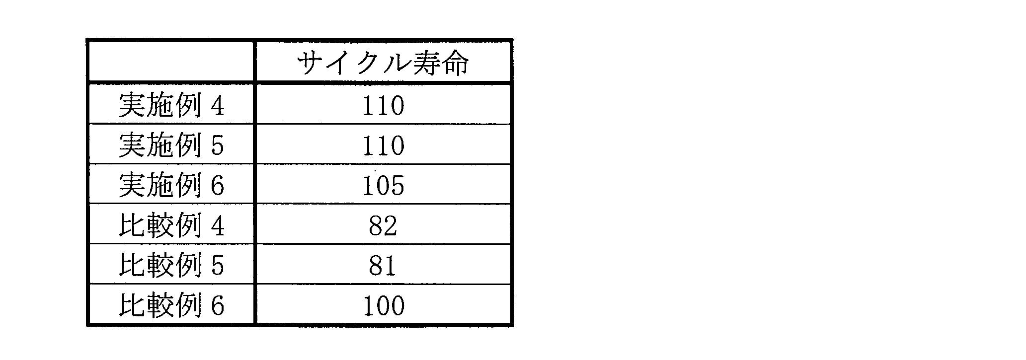
負極活物質A1の代わりに負極活物質A2を用いたこと以外は、実施例4と同様の方法で負極活物質A5及び電池T5を作製した。
負極活物質A1の代わりに負極活物質A3を用いたこと以外は、実施例4と同様の方法で負極活物質A6及び電池T6を作製した。
負極活物質A1の代わりに比較例1で用いた負極活物質B1を用いたこと以外は、実施4と同様の方法で負極活物質B4及び電池R4を作製した。
負極活物質B1の代わりに負極活物質B2を用いたこと以外は、比較例4と同様の方法で負極活物質B5及び電池R5を作製した。
負極活物質B1の代わりに負極活物質B3を用いたこと以外は、比較例4と同様の方法で負極活物質B6及び電池R6を作製した。
・充電
1It(800mA)の電流で電圧が4.2Vになるまで定電流充電を行い、その後4.2Vの定電圧で電流が1/20It(40mA)になるまで定電圧充電した。
・放電
1It(800mA)の電流で電圧が2.75Vになるまで定電流放電を行った。
・休止
上記充電と上記放電との間の休止期間は10分とした。
上記充放電サイクルを繰り返して、1サイクル目の放電容量の80%に達するサイクル数を測定し、これをサイクル寿命とした。なお、各電池のサイクル寿命は、電池R6(比較例6)のサイクル寿命を100とした指数である。
Claims (9)
- Li2zSiO(2+z){0<z<2}で表されるリチウムシリケート相と、
前記リチウムシリケート相中に分散したシリコン粒子と、
を含む母粒子を備え、
前記母粒子断面の反射電子像の画像解析により求められる対称性が1.5以下であり、
ここで、前記対称性とは、前記反射電子像の各ピクセルについて256階調のグレーレベルで色判定した結果のヒストグラムのピークの高階調側半値半幅bを当該ピークの低階調側半値半幅aで除した値(b/a)である、非水電解質二次電池用負極活物質。 - XRD測定により得られるXRDパターンにおいて、リチウムシリケートの(111)面の回析ピークの半値幅が0.05°以上である、請求項1に記載の非水電解質二次電池用負極活物質。
- XRD測定により得られるXRDパターンにおいて、Si(111)面の回析ピークの強度がリチウムシリケートの(111)面の回析ピークの強度よりも大きい、請求項1又は2に記載の非水電解質二次電池用負極活物質。
- 充放電後の前記非水電解質二次電池用負極活物質には、Li4SiO4が含まれない、請求項1~3のいずれか1項に記載の非水電解質二次電池用負極活物質。
- 前記XRDパターンの2θ=25°にSiO2の回析ピークが観察されない、請求項1~4のいずれか1項に記載の非水電解質二次電池用負極活物質。
- 前記リチウムシリケート相は、Li2Si2O5を主成分とし、
前記XRDパターンにおけるLi2Si2O5(111)面の回析ピークの半値幅が0.09°以上である、請求項1~5のいずれか1項に記載の非水電解質二次電池用負極活物質。 - 前記リチウムシリケート相は、Li2SiO3を主成分とし、
前記XRDパターンにおけるLi2SiO3(111)面の回析ピークの半値幅が0.10°以上である、請求項1~5のいずれか1項に記載の非水電解質二次電池用負極活物質。 - 前記リチウムシリケート相と、前記シリコン粒子とで構成される母粒子の表面には、導電層が形成されている、請求項1~7のいずれか1項に記載の非水電解質二次電池用負極活物質。
- 請求項1~8のいずれか1項に記載の非水電解質二次電池用負極活物質を用いた負極と、正極と、非水電解質と、を備えた非水電解質二次電池。
Priority Applications (3)
| Application Number | Priority Date | Filing Date | Title |
|---|---|---|---|
| CN201680005156.6A CN107210435B (zh) | 2015-01-28 | 2016-01-18 | 非水电解质二次电池用负极活性物质和非水电解质二次电池 |
| US15/526,532 US10516158B2 (en) | 2015-01-28 | 2016-01-18 | Negative-electrode active material for non-aqueous electrolyte secondary battery and non-aqueous electrolyte secondary battery |
| JP2016571840A JPWO2016121325A1 (ja) | 2015-01-28 | 2016-01-18 | 非水電解質二次電池用負極活物質及び非水電解質二次電池 |
Applications Claiming Priority (4)
| Application Number | Priority Date | Filing Date | Title |
|---|---|---|---|
| JP2015-014158 | 2015-01-28 | ||
| JP2015014158 | 2015-01-28 | ||
| JP2015245398 | 2015-12-16 | ||
| JP2015-245398 | 2015-12-16 |
Publications (1)
| Publication Number | Publication Date |
|---|---|
| WO2016121325A1 true WO2016121325A1 (ja) | 2016-08-04 |
Family
ID=56542950
Family Applications (1)
| Application Number | Title | Priority Date | Filing Date |
|---|---|---|---|
| PCT/JP2016/000221 Ceased WO2016121325A1 (ja) | 2015-01-28 | 2016-01-18 | 非水電解質二次電池用負極活物質及び非水電解質二次電池 |
Country Status (4)
| Country | Link |
|---|---|
| US (1) | US10516158B2 (ja) |
| JP (2) | JPWO2016121325A1 (ja) |
| CN (1) | CN107210435B (ja) |
| WO (1) | WO2016121325A1 (ja) |
Cited By (4)
| Publication number | Priority date | Publication date | Assignee | Title |
|---|---|---|---|---|
| JPWO2019107033A1 (ja) * | 2017-11-29 | 2020-11-19 | パナソニックIpマネジメント株式会社 | リチウムイオン電池 |
| JPWO2019130787A1 (ja) * | 2017-12-28 | 2021-01-21 | パナソニックIpマネジメント株式会社 | 非水電解質二次電池用負極活物質 |
| JPWO2021153077A1 (ja) * | 2020-01-31 | 2021-08-05 | ||
| US11670772B2 (en) * | 2017-11-30 | 2023-06-06 | Panasonic Intellectual Property Management Co., Ltd. | Negative electrode active material for lithium ion battery, and lithium ion battery |
Families Citing this family (4)
| Publication number | Priority date | Publication date | Assignee | Title |
|---|---|---|---|---|
| KR102285979B1 (ko) * | 2017-09-11 | 2021-08-04 | 주식회사 엘지에너지솔루션 | 음극 활물질, 상기 음극 활물질을 포함하는 음극, 및 상기 음극을 포함하는 이차 전지 |
| CN108321368B (zh) * | 2017-12-28 | 2020-07-17 | 合肥国轩高科动力能源有限公司 | 一种聚合物包覆硅/偏硅酸锂负极材料及其制备方法 |
| CN111326721B (zh) * | 2018-12-17 | 2021-05-07 | 荣盛盟固利新能源科技有限公司 | 一种复合负极预嵌锂材料的制备方法 |
| EP4160738A4 (en) * | 2020-05-29 | 2023-11-29 | Panasonic Intellectual Property Management Co., Ltd. | ACTIVE SUBSTANCE OF NEGATIVE ELECTRODE FOR SECONDARY BATTERY AND SECONDARY BATTERY |
Citations (3)
| Publication number | Priority date | Publication date | Assignee | Title |
|---|---|---|---|---|
| JP2011222151A (ja) * | 2010-04-05 | 2011-11-04 | Shin Etsu Chem Co Ltd | 非水電解質二次電池用負極材及び非水電解質二次電池用負極材の製造方法並びにリチウムイオン二次電池 |
| JP2013161705A (ja) * | 2012-02-07 | 2013-08-19 | Toyota Industries Corp | 二次電池用活物質およびその製造方法 |
| JP2014103019A (ja) * | 2012-11-21 | 2014-06-05 | Shin Etsu Chem Co Ltd | 蓄電デバイス用負極材、蓄電デバイス用電極および蓄電デバイスならびにそれらの製造方法 |
Family Cites Families (13)
| Publication number | Priority date | Publication date | Assignee | Title |
|---|---|---|---|---|
| JP4702510B2 (ja) | 2001-09-05 | 2011-06-15 | 信越化学工業株式会社 | リチウム含有酸化珪素粉末及びその製造方法 |
| WO2005064714A1 (ja) * | 2003-12-26 | 2005-07-14 | Nec Corporation | 二次電池用負極材料、二次電池用負極およびそれを用いた二次電池 |
| JP4533822B2 (ja) | 2005-08-24 | 2010-09-01 | 株式会社東芝 | 非水電解質電池および負極活物質 |
| JP5411781B2 (ja) | 2010-04-05 | 2014-02-12 | 信越化学工業株式会社 | 非水電解質二次電池用負極材及び非水電解質二次電池用負極材の製造方法並びにリチウムイオン二次電池 |
| JP4868556B2 (ja) | 2010-04-23 | 2012-02-01 | 日立マクセルエナジー株式会社 | リチウム二次電池 |
| JP2013235685A (ja) | 2012-05-07 | 2013-11-21 | Furukawa Electric Co Ltd:The | リチウムイオン二次電池用負極材料およびそれを用いたリチウムイオン二次電池用負極、並びにそれを用いたリチウムイオン二次電池 |
| JP5898572B2 (ja) | 2012-06-13 | 2016-04-06 | 信越化学工業株式会社 | 非水電解質二次電池用負極材の製造方法及び非水電解質二次電池の製造方法 |
| CN104981925A (zh) * | 2013-01-29 | 2015-10-14 | 三洋电机株式会社 | 非水电解质二次电池用负极活性物质、使用该负极活性物质的非水电解质二次电池用负极、以及使用该负极的非水电解质二次电池 |
| JP6058704B2 (ja) | 2013-01-30 | 2017-01-11 | 三洋電機株式会社 | 非水電解質二次電池用負極活物質、当該負極活物質を用いた非水電解質二次電池用負極、及び当該負極を用いた非水電解質二次電池 |
| CN103400971B (zh) * | 2013-07-29 | 2016-07-06 | 宁德新能源科技有限公司 | 硅基复合材料及其制备方法以及其应用 |
| JP5870129B2 (ja) | 2014-02-12 | 2016-02-24 | 株式会社大阪チタニウムテクノロジーズ | リチウムイオン二次電池の負極用粉末、およびその製造方法 |
| WO2016121324A1 (ja) * | 2015-01-28 | 2016-08-04 | 三洋電機株式会社 | 非水電解質二次電池用負極活物質及び非水電解質二次電池 |
| WO2016121326A1 (ja) * | 2015-01-28 | 2016-08-04 | 三洋電機株式会社 | 非水電解質二次電池用負極活物質及び非水電解質二次電池 |
-
2016
- 2016-01-18 US US15/526,532 patent/US10516158B2/en active Active
- 2016-01-18 CN CN201680005156.6A patent/CN107210435B/zh active Active
- 2016-01-18 JP JP2016571840A patent/JPWO2016121325A1/ja active Pending
- 2016-01-18 WO PCT/JP2016/000221 patent/WO2016121325A1/ja not_active Ceased
-
2020
- 2020-05-01 JP JP2020081337A patent/JP7004764B2/ja active Active
Patent Citations (3)
| Publication number | Priority date | Publication date | Assignee | Title |
|---|---|---|---|---|
| JP2011222151A (ja) * | 2010-04-05 | 2011-11-04 | Shin Etsu Chem Co Ltd | 非水電解質二次電池用負極材及び非水電解質二次電池用負極材の製造方法並びにリチウムイオン二次電池 |
| JP2013161705A (ja) * | 2012-02-07 | 2013-08-19 | Toyota Industries Corp | 二次電池用活物質およびその製造方法 |
| JP2014103019A (ja) * | 2012-11-21 | 2014-06-05 | Shin Etsu Chem Co Ltd | 蓄電デバイス用負極材、蓄電デバイス用電極および蓄電デバイスならびにそれらの製造方法 |
Cited By (9)
| Publication number | Priority date | Publication date | Assignee | Title |
|---|---|---|---|---|
| JPWO2019107033A1 (ja) * | 2017-11-29 | 2020-11-19 | パナソニックIpマネジメント株式会社 | リチウムイオン電池 |
| JP7209265B2 (ja) | 2017-11-29 | 2023-01-20 | パナソニックIpマネジメント株式会社 | リチウムイオン電池 |
| US11984604B2 (en) * | 2017-11-29 | 2024-05-14 | Panasonic Intellectual Property Management Co., Ltd. | Lithium ion battery |
| US11670772B2 (en) * | 2017-11-30 | 2023-06-06 | Panasonic Intellectual Property Management Co., Ltd. | Negative electrode active material for lithium ion battery, and lithium ion battery |
| JPWO2019130787A1 (ja) * | 2017-12-28 | 2021-01-21 | パナソニックIpマネジメント株式会社 | 非水電解質二次電池用負極活物質 |
| JP7209266B2 (ja) | 2017-12-28 | 2023-01-20 | パナソニックIpマネジメント株式会社 | 非水電解質二次電池用負極活物質 |
| US11990606B2 (en) * | 2017-12-28 | 2024-05-21 | Panasonic Intellectual Property Management Co., Ltd. | Negative electrode active material for non-aqueous electrolyte secondary batteries |
| JPWO2021153077A1 (ja) * | 2020-01-31 | 2021-08-05 | ||
| JP7813998B2 (ja) | 2020-01-31 | 2026-02-16 | パナソニックIpマネジメント株式会社 | 二次電池用負極活物質およびその製造方法、ならびに二次電池 |
Also Published As
| Publication number | Publication date |
|---|---|
| JP7004764B2 (ja) | 2022-01-21 |
| JP2020119908A (ja) | 2020-08-06 |
| CN107210435B (zh) | 2021-03-26 |
| JPWO2016121325A1 (ja) | 2017-11-09 |
| US20170324083A1 (en) | 2017-11-09 |
| CN107210435A (zh) | 2017-09-26 |
| US10516158B2 (en) | 2019-12-24 |
Similar Documents
| Publication | Publication Date | Title |
|---|---|---|
| JP6685938B2 (ja) | 非水電解質二次電池用負極活物質及び非水電解質二次電池 | |
| JP6833511B2 (ja) | 非水電解質二次電池用負極活物質及び非水電解質二次電池 | |
| US10312516B2 (en) | Negative-electrode active material for non-aqueous electrolyte secondary battery, and non-aqueous electrolyte secondary battery | |
| JP6847667B2 (ja) | 非水電解質二次電池用負極活物質及び非水電解質二次電池 | |
| JP7004764B2 (ja) | 非水電解質二次電池用負極活物質及び非水電解質二次電池 | |
| CN107112521B (zh) | 非水电解质二次电池用负极活性物质和非水电解质二次电池 | |
| JP6613250B2 (ja) | 非水電解質二次電池用負極活物質及び非水電解質二次電池 | |
| JPWO2017051500A1 (ja) | 非水電解質二次電池用負極活物質及び負極 | |
| JP6918638B2 (ja) | 非水電解質二次電池 | |
| JP7432882B2 (ja) | 非水電解質二次電池 |
Legal Events
| Date | Code | Title | Description |
|---|---|---|---|
| 121 | Ep: the epo has been informed by wipo that ep was designated in this application |
Ref document number: 16742930 Country of ref document: EP Kind code of ref document: A1 |
|
| WWE | Wipo information: entry into national phase |
Ref document number: 15526532 Country of ref document: US |
|
| ENP | Entry into the national phase |
Ref document number: 2016571840 Country of ref document: JP Kind code of ref document: A |
|
| NENP | Non-entry into the national phase |
Ref country code: DE |
|
| 122 | Ep: pct application non-entry in european phase |
Ref document number: 16742930 Country of ref document: EP Kind code of ref document: A1 |