WO2016117253A1 - 排気ガス処理装置及び基板処理装置 - Google Patents
排気ガス処理装置及び基板処理装置 Download PDFInfo
- Publication number
- WO2016117253A1 WO2016117253A1 PCT/JP2015/085390 JP2015085390W WO2016117253A1 WO 2016117253 A1 WO2016117253 A1 WO 2016117253A1 JP 2015085390 W JP2015085390 W JP 2015085390W WO 2016117253 A1 WO2016117253 A1 WO 2016117253A1
- Authority
- WO
- WIPO (PCT)
- Prior art keywords
- filter
- exhaust gas
- reaction
- container
- processing apparatus
- Prior art date
- Legal status (The legal status is an assumption and is not a legal conclusion. Google has not performed a legal analysis and makes no representation as to the accuracy of the status listed.)
- Ceased
Links
Images



Classifications
-
- B—PERFORMING OPERATIONS; TRANSPORTING
- B01—PHYSICAL OR CHEMICAL PROCESSES OR APPARATUS IN GENERAL
- B01D—SEPARATION
- B01D46/00—Filters or filtering processes specially modified for separating dispersed particles from gases or vapours
- B01D46/66—Regeneration of the filtering material or filter elements inside the filter
- B01D46/68—Regeneration of the filtering material or filter elements inside the filter by means acting on the cake side involving movement with regard to the filter elements
- B01D46/681—Regeneration of the filtering material or filter elements inside the filter by means acting on the cake side involving movement with regard to the filter elements by scrapers, brushes or the like
-
- B—PERFORMING OPERATIONS; TRANSPORTING
- B01—PHYSICAL OR CHEMICAL PROCESSES OR APPARATUS IN GENERAL
- B01D—SEPARATION
- B01D46/00—Filters or filtering processes specially modified for separating dispersed particles from gases or vapours
- B01D46/24—Particle separators, e.g. dust precipitators, using rigid hollow filter bodies
-
- B—PERFORMING OPERATIONS; TRANSPORTING
- B01—PHYSICAL OR CHEMICAL PROCESSES OR APPARATUS IN GENERAL
- B01D—SEPARATION
- B01D46/00—Filters or filtering processes specially modified for separating dispersed particles from gases or vapours
- B01D46/66—Regeneration of the filtering material or filter elements inside the filter
- B01D46/74—Regeneration of the filtering material or filter elements inside the filter by forces created by movement of the filter element
- B01D46/76—Regeneration of the filtering material or filter elements inside the filter by forces created by movement of the filter element involving vibrations
-
- C—CHEMISTRY; METALLURGY
- C23—COATING METALLIC MATERIAL; COATING MATERIAL WITH METALLIC MATERIAL; CHEMICAL SURFACE TREATMENT; DIFFUSION TREATMENT OF METALLIC MATERIAL; COATING BY VACUUM EVAPORATION, BY SPUTTERING, BY ION IMPLANTATION OR BY CHEMICAL VAPOUR DEPOSITION, IN GENERAL; INHIBITING CORROSION OF METALLIC MATERIAL OR INCRUSTATION IN GENERAL
- C23C—COATING METALLIC MATERIAL; COATING MATERIAL WITH METALLIC MATERIAL; SURFACE TREATMENT OF METALLIC MATERIAL BY DIFFUSION INTO THE SURFACE, BY CHEMICAL CONVERSION OR SUBSTITUTION; COATING BY VACUUM EVAPORATION, BY SPUTTERING, BY ION IMPLANTATION OR BY CHEMICAL VAPOUR DEPOSITION, IN GENERAL
- C23C16/00—Chemical coating by decomposition of gaseous compounds, without leaving reaction products of surface material in the coating, i.e. chemical vapour deposition [CVD] processes
- C23C16/22—Chemical coating by decomposition of gaseous compounds, without leaving reaction products of surface material in the coating, i.e. chemical vapour deposition [CVD] processes characterised by the deposition of inorganic material, other than metallic material
- C23C16/30—Deposition of compounds, mixtures or solid solutions, e.g. borides, carbides, nitrides
- C23C16/301—AIII BV compounds, where A is Al, Ga, In or Tl and B is N, P, As, Sb or Bi
-
- C—CHEMISTRY; METALLURGY
- C23—COATING METALLIC MATERIAL; COATING MATERIAL WITH METALLIC MATERIAL; CHEMICAL SURFACE TREATMENT; DIFFUSION TREATMENT OF METALLIC MATERIAL; COATING BY VACUUM EVAPORATION, BY SPUTTERING, BY ION IMPLANTATION OR BY CHEMICAL VAPOUR DEPOSITION, IN GENERAL; INHIBITING CORROSION OF METALLIC MATERIAL OR INCRUSTATION IN GENERAL
- C23C—COATING METALLIC MATERIAL; COATING MATERIAL WITH METALLIC MATERIAL; SURFACE TREATMENT OF METALLIC MATERIAL BY DIFFUSION INTO THE SURFACE, BY CHEMICAL CONVERSION OR SUBSTITUTION; COATING BY VACUUM EVAPORATION, BY SPUTTERING, BY ION IMPLANTATION OR BY CHEMICAL VAPOUR DEPOSITION, IN GENERAL
- C23C16/00—Chemical coating by decomposition of gaseous compounds, without leaving reaction products of surface material in the coating, i.e. chemical vapour deposition [CVD] processes
- C23C16/44—Chemical coating by decomposition of gaseous compounds, without leaving reaction products of surface material in the coating, i.e. chemical vapour deposition [CVD] processes characterised by the method of coating
- C23C16/4412—Details relating to the exhausts, e.g. pumps, filters, scrubbers, particle traps
-
- C—CHEMISTRY; METALLURGY
- C23—COATING METALLIC MATERIAL; COATING MATERIAL WITH METALLIC MATERIAL; CHEMICAL SURFACE TREATMENT; DIFFUSION TREATMENT OF METALLIC MATERIAL; COATING BY VACUUM EVAPORATION, BY SPUTTERING, BY ION IMPLANTATION OR BY CHEMICAL VAPOUR DEPOSITION, IN GENERAL; INHIBITING CORROSION OF METALLIC MATERIAL OR INCRUSTATION IN GENERAL
- C23C—COATING METALLIC MATERIAL; COATING MATERIAL WITH METALLIC MATERIAL; SURFACE TREATMENT OF METALLIC MATERIAL BY DIFFUSION INTO THE SURFACE, BY CHEMICAL CONVERSION OR SUBSTITUTION; COATING BY VACUUM EVAPORATION, BY SPUTTERING, BY ION IMPLANTATION OR BY CHEMICAL VAPOUR DEPOSITION, IN GENERAL
- C23C16/00—Chemical coating by decomposition of gaseous compounds, without leaving reaction products of surface material in the coating, i.e. chemical vapour deposition [CVD] processes
- C23C16/44—Chemical coating by decomposition of gaseous compounds, without leaving reaction products of surface material in the coating, i.e. chemical vapour deposition [CVD] processes characterised by the method of coating
- C23C16/448—Chemical coating by decomposition of gaseous compounds, without leaving reaction products of surface material in the coating, i.e. chemical vapour deposition [CVD] processes characterised by the method of coating characterised by the method used for generating reactive gas streams, e.g. by evaporation or sublimation of precursor materials
- C23C16/4481—Chemical coating by decomposition of gaseous compounds, without leaving reaction products of surface material in the coating, i.e. chemical vapour deposition [CVD] processes characterised by the method of coating characterised by the method used for generating reactive gas streams, e.g. by evaporation or sublimation of precursor materials by evaporation using carrier gas in contact with the source material
-
- C—CHEMISTRY; METALLURGY
- C23—COATING METALLIC MATERIAL; COATING MATERIAL WITH METALLIC MATERIAL; CHEMICAL SURFACE TREATMENT; DIFFUSION TREATMENT OF METALLIC MATERIAL; COATING BY VACUUM EVAPORATION, BY SPUTTERING, BY ION IMPLANTATION OR BY CHEMICAL VAPOUR DEPOSITION, IN GENERAL; INHIBITING CORROSION OF METALLIC MATERIAL OR INCRUSTATION IN GENERAL
- C23C—COATING METALLIC MATERIAL; COATING MATERIAL WITH METALLIC MATERIAL; SURFACE TREATMENT OF METALLIC MATERIAL BY DIFFUSION INTO THE SURFACE, BY CHEMICAL CONVERSION OR SUBSTITUTION; COATING BY VACUUM EVAPORATION, BY SPUTTERING, BY ION IMPLANTATION OR BY CHEMICAL VAPOUR DEPOSITION, IN GENERAL
- C23C16/00—Chemical coating by decomposition of gaseous compounds, without leaving reaction products of surface material in the coating, i.e. chemical vapour deposition [CVD] processes
- C23C16/44—Chemical coating by decomposition of gaseous compounds, without leaving reaction products of surface material in the coating, i.e. chemical vapour deposition [CVD] processes characterised by the method of coating
- C23C16/448—Chemical coating by decomposition of gaseous compounds, without leaving reaction products of surface material in the coating, i.e. chemical vapour deposition [CVD] processes characterised by the method of coating characterised by the method used for generating reactive gas streams, e.g. by evaporation or sublimation of precursor materials
- C23C16/4488—Chemical coating by decomposition of gaseous compounds, without leaving reaction products of surface material in the coating, i.e. chemical vapour deposition [CVD] processes characterised by the method of coating characterised by the method used for generating reactive gas streams, e.g. by evaporation or sublimation of precursor materials by in situ generation of reactive gas by chemical or electrochemical reaction
-
- C—CHEMISTRY; METALLURGY
- C30—CRYSTAL GROWTH
- C30B—SINGLE-CRYSTAL GROWTH; UNIDIRECTIONAL SOLIDIFICATION OF EUTECTIC MATERIAL OR UNIDIRECTIONAL DEMIXING OF EUTECTOID MATERIAL; REFINING BY ZONE-MELTING OF MATERIAL; PRODUCTION OF A HOMOGENEOUS POLYCRYSTALLINE MATERIAL WITH DEFINED STRUCTURE; SINGLE CRYSTALS OR HOMOGENEOUS POLYCRYSTALLINE MATERIAL WITH DEFINED STRUCTURE; AFTER-TREATMENT OF SINGLE CRYSTALS OR A HOMOGENEOUS POLYCRYSTALLINE MATERIAL WITH DEFINED STRUCTURE; APPARATUS THEREFOR
- C30B25/00—Single-crystal growth by chemical reaction of reactive gases, e.g. chemical vapour-deposition growth
- C30B25/02—Epitaxial-layer growth
-
- Y—GENERAL TAGGING OF NEW TECHNOLOGICAL DEVELOPMENTS; GENERAL TAGGING OF CROSS-SECTIONAL TECHNOLOGIES SPANNING OVER SEVERAL SECTIONS OF THE IPC; TECHNICAL SUBJECTS COVERED BY FORMER USPC CROSS-REFERENCE ART COLLECTIONS [XRACs] AND DIGESTS
- Y02—TECHNOLOGIES OR APPLICATIONS FOR MITIGATION OR ADAPTATION AGAINST CLIMATE CHANGE
- Y02C—CAPTURE, STORAGE, SEQUESTRATION OR DISPOSAL OF GREENHOUSE GASES [GHG]
- Y02C20/00—Capture or disposal of greenhouse gases
- Y02C20/30—Capture or disposal of greenhouse gases of perfluorocarbons [PFC], hydrofluorocarbons [HFC] or sulfur hexafluoride [SF6]
Definitions
- the present invention relates to an exhaust gas processing apparatus and a substrate processing apparatus connected to a reaction vessel for processing a substrate.
- the filter when the filter captures a predetermined amount of reaction by-products, the filter may become clogged. Therefore, it is necessary to replace the filter before the filter is completely clogged.
- An object of the present invention is to provide a technique capable of solving the above-described problems and reducing the frequency of filter replacement.
- An exhaust gas processing apparatus connected to a reaction vessel for processing a substrate, A container into which exhaust gas discharged from the reaction container is introduced; A filter provided in the container for capturing reaction by-products contained in the exhaust gas; There is provided an exhaust gas processing apparatus comprising: a collision member that collides with the filter and removes the reaction byproduct captured by the filter from the filter by the impact.
- a substrate processing apparatus comprising an exhaust gas processing apparatus connected to a reaction vessel for processing a substrate,
- the exhaust gas treatment device comprises: A container into which exhaust gas discharged from the reaction container is introduced; A filter provided in the container for capturing reaction by-products contained in the exhaust gas; There is provided a substrate processing apparatus comprising: a collision member that collides with the filter and removes the reaction byproduct captured by the filter from the filter by the impact.
- the frequency of filter replacement can be reduced.
- FIG. 1 is a schematic vertical sectional view of a substrate processing apparatus including an exhaust gas processing apparatus according to an embodiment of the present invention. It is the schematic of the exhaust-gas processing apparatus concerning one Embodiment of this invention, (a) shows a longitudinal cross-sectional view, (b) shows a cross-sectional view.
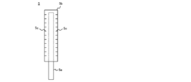
- the schematic plan view of the collision member with which the exhaust-gas processing apparatus concerning one Embodiment of this invention is provided is shown.
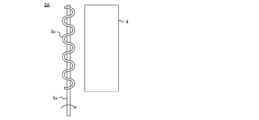
- the schematic of the collision member with which the exhaust-gas processing apparatus concerning other embodiment of this invention is provided is shown.
- the cross-sectional schematic of the exhaust-gas processing apparatus concerning other embodiment of this invention is shown.
- ⁇ One Embodiment of the Present Invention> (1) Configuration of Substrate Processing Apparatus and Exhaust Gas Processing Apparatus
- a substrate processing apparatus according to an embodiment of the present invention and an exhaust gas processing apparatus included in the substrate processing apparatus will be described with reference mainly to FIGS. While explaining.
- the substrate processing apparatus is a hydride vapor phase epitaxy (HVPE) apparatus
- HVPE hydride vapor phase epitaxy
- the HVPE apparatus as the substrate processing apparatus 20 includes a reaction vessel 21 formed of a heat resistant material such as quartz (SiO 2 ).
- a processing chamber 22 is formed in the cylindrical hollow portion in the reaction vessel 21.
- a susceptor 23 is provided as a substrate support unit that supports the substrate 100 in the processing chamber 22.
- the susceptor 23 is provided with a rotating shaft 23a, and the susceptor 23 is configured to be rotatable.
- the 1st heater 24 and the 2nd heater 25 are provided in the outer periphery of the reaction container 21 as a heating part.
- a processing gas generator 26 described later is heated to a predetermined temperature (for example, 600 ° C. to 900 ° C.) mainly by the first heater 24.
- the substrate 100 in the processing chamber 22 is heated to a predetermined temperature (for example, 500 ° C. to 1200 ° C.) mainly by the second heater 25.
- a processing gas generator 26 that generates a processing gas by reacting the metal raw material 27 with a reactive gas.
- the processing gas generator 26 includes a container 28 that stores a metal raw material 27.
- the container 28 is formed in a rectangular shape in plan view.
- the container 28 is formed of a nonmetallic material having heat resistance and corrosion resistance.
- the container 28 may be made of high-purity quartz.
- the metal raw material 27 for example, a raw material that is solid at room temperature is used.
- the metal raw material 27 may be solid or liquid depending on the temperature in the processing gas generator 26 and the metal used.
- the reaction vessel 21 is provided with a first process gas supply pipe 29 and a reaction gas supply pipe 30 in an airtight manner so as to penetrate the side portion of the reaction vessel 21.
- the first processing gas supply pipe 29 and the reaction gas supply pipe 30 are formed of a nonmetallic material (for example, quartz) having heat resistance, corrosion resistance, and the like.
- a valve 29b is provided as a valve for performing the above. From the first processing gas supply pipe 29, for example, ammonia (NH 3 ) gas is supplied as the first processing gas to the substrate 100 in the processing chamber 22.
- NH 3 ammonia
- a reaction gas supply source 30 a and a valve 30 b as a valve for supplying and stopping the reaction gas to the process gas generator 26 are provided in order from the upstream side.
- chlorine (Cl 2 ) gas or hydrogen chloride (HCl) gas is supplied from the reaction gas supply pipe 30 as a reaction gas into the processing gas generator 26 (container 28).
- the processing gas generator 26 includes a second processing gas supply pipe 31 that supplies the processing gas (second processing gas) generated in the processing gas generator 26 to the substrate 100.
- the second processing gas supply pipe 31 is formed of a nonmetallic material (for example, quartz) having heat resistance, corrosion resistance, and the like.
- gallium chloride (GaCl) gas is supplied from the second processing gas supply pipe 31 to the substrate 100 in the processing chamber 22 as the second processing gas.
- the reaction vessel 21 is provided with an exhaust pipe 32 for exhausting the atmosphere in the processing chamber 22.
- the exhaust pipe 32 is provided with a vacuum pump (or blower) 32a as an exhaust device.
- the exhaust gas treatment device 1 is connected to the reaction vessel 21. Specifically, the exhaust gas treatment device 1 is connected to the exhaust pipe 32 on the upstream side of the vacuum pump 32a. The exhaust gas treatment device 1 is configured to remove reaction byproducts contained in the exhaust gas discharged from the reaction vessel 21.
- the exhaust gas treatment device 1 includes a container 2 into which exhaust gas discharged from the reaction container 21 is introduced.
- the container 2 is made of a corrosion-resistant metal material (for example, SUS) or a non-metal material (for example, quartz) having heat resistance and corrosion resistance.
- a partition wall 2c that partitions (divides) the space in the container 2 into two upper and lower spaces is provided.
- the space below the partition wall 2c in the container 2 becomes a chamber 2a (exhaust gas introduction chamber 2a) into which exhaust gas is introduced.
- the space above the partition wall 2c in the container 2 becomes a chamber 2b (filtered gas introduction chamber 2b) into which exhaust gas (filtered gas) from which reaction byproducts have been removed (filtered) by a filter 4 described later is introduced.
- the exhaust gas introduction chamber 2a and the filtered gas introduction chamber 2b are communicated with each other through a filter 4 described later.
- the partition wall 2c is provided with a plurality of (for example, four) filters 4 for capturing (filtering) reaction byproducts contained in the exhaust gas.
- the filter 4 is formed in a cylindrical shape having a cylindrical hollow portion of, for example, a cylindrical shape or a rectangular tube shape.
- the exhaust pipe 32 is hermetically connected to the container 2 (for example, the side wall) constituting the exhaust gas introduction chamber 2a, and an introduction port 3a for introducing the exhaust gas discharged from the reaction container 21 is provided in the container 2. ing.
- a container 2 (for example, a top plate) constituting the filtered gas introduction chamber 2b is provided with a discharge port 3b through which the filtered gas that has passed through the filter 4 is discharged from the container 2.
- the exhaust gas introduced from the introduction port 3a flows through the exhaust gas introduction chamber 2a, passes through the filter 4, is introduced into the filtered gas introduction chamber 2b, and is discharged from the discharge port 3b to the outside of the container 2. It is configured to be discharged. While the exhaust gas passes through the filter 4, reaction byproducts contained in the exhaust gas are captured by the filter 4.
- the exhaust gas treatment device 1 includes a collision member 5 that causes the filter 4 to collide (hit).
- the collision member 5 is preferably disposed between the adjacent filters 4 and 4.
- the collision member 5 is made of, for example, a metal material having corrosion resistance (for example, SUS).
- SUS corrosion resistance
- the collision member 5 is configured to be slidable with respect to at least a part of the outer peripheral surface of the filter 4 after colliding with the filter 4.
- the collision member 5 is configured to be movable along the circumferential direction of the filter 4 so as to rub at least a part of the outer peripheral side surface of the filter 4 after colliding with the filter 4.
- the collision member 5 includes, for example, a rod-shaped member 5a, and is configured to cause the rod-shaped member 5a to collide with the filter 4.
- the rod-like member 5a is provided along the side wall of the filter 4 (that is, extends along the side wall of the container 2).
- the rod-shaped member 5a is made of, for example, a metal material having corrosion resistance (for example, SUS).
- a plate-like member 5 b formed of a flexible member is attached (provided) to a portion of the rod-shaped member 5 a that collides with the filter 4.
- a rubber member such as silicon rubber, natural rubber, or synthetic rubber can be used.
- the plate-like member 5b preferably has a slit 5c on its side, for example, and is configured to reduce impact applied to the filter 4 by being deformed when colliding with the filter 4.
- Each of the slits 5c has a predetermined width and is formed in the plate-like member 5b at a predetermined interval.
- the rod-like member 5a is supported by the support member 6 from below.
- the support member 6 is provided airtight so as to penetrate the side wall of the container 2.
- the support member 6 is made of, for example, a metal material having corrosion resistance (for example, SUS).
- a handle 7 as a drive mechanism for moving the collision member 5 is provided outside the container 2 in the support member 6. Thereby, the collision member 5 can be moved from the outside of the container 2.
- the support member 6 may be included in the drive mechanism.
- the plate-like member 5b is moved in the predetermined direction via the support member 6 and the rod-like member 5a, and the plate-like member 5b is moved against at least a part of the outer peripheral surface of the filter 4. Can be slid.
- the exhaust gas treatment device 1 includes a trapping amount measurement sensor 8 that measures the amount of trapped reaction by-products (capture amount).
- the trapping amount measured by the trapping amount measuring sensor 8 exceeds a predetermined value
- the collision member 5 is moved by the handle 7 to cause the collision member 5 (for example, the plate-like member 5b) to collide with the filter 4.
- a pressure measurement sensor that detects the pressure in the container 2 is used as the trapping amount measurement sensor 8, and when the pressure (internal pressure) in the container 2 (for example, in the exhaust gas introduction chamber 2 a) becomes a predetermined value or more, the handle 7
- the collision member 5 is moved by this to cause the collision member 5 (for example, the plate-like member 5b) to collide with the filter 4.
- a deposition space 10 for depositing reaction byproducts removed from the filter 4 is provided.
- the deposition space 10 is provided in the lower part of the container 2 (exhaust gas introduction chamber 2a) in the vertical direction.
- the introduction port 3a is preferably provided above the deposition space 10 so as not to be blocked even when reaction by-products are deposited in the deposition space 10.
- the deposition space 10 is preferably formed in a region below the introduction port 3 a in the container 2.
- the exhaust gas processing apparatus 1 is configured to introduce exhaust gas into the deposition space 10 from the introduction port 3a, and cause the exhaust gas to collide with the inner wall of the deposition space 10 (the inner wall of the container 2 constituting the deposition space 10).
- the inlet 3a is preferably provided with a rectifying plate 11 that guides exhaust gas that has passed through the inlet 3a into the deposition space 10.
- a nozzle may be connected to the introduction port 3a.
- the temperature of the inner wall of the deposition space 10 is lower than the temperature of the exhaust gas. For this reason, when the exhaust gas collides with the inner wall of the deposition space 10, the exhaust gas is cooled.
- the reaction by-product contained in the exhaust gas is also cooled and liquefied or solidified. Therefore, by causing the exhaust gas to collide with the inner wall of the deposition space 10, at least a part of the reaction byproduct contained in the exhaust gas can be adsorbed on the inner wall of the deposition space 10.
- Substrate loading process First, for example, Ga solid is accommodated (supplemented) in the processing gas generator 26 (container 28). Then, for example, a sapphire substrate as the substrate 100 is carried into the processing chamber 22 and placed on the susceptor 23.
- valve 30b is opened, and supply of the reaction gas (for example, HCl gas) from the reaction gas supply pipe 30 into the processing gas generator 26 is started.
- the reaction gas for example, HCl gas
- the Ga melt and the reaction gas react in the processing gas generator 26 to generate a second processing gas (for example, GaCl gas).
- the second processing gas generated in the processing gas generator 26 is supplied from the second processing gas supply pipe 31 to the substrate 100 in the processing chamber 22. Then, the first processing gas and the second processing gas are reacted to form a GaN film having a predetermined thickness on the substrate 100.
- the exhaust gas is exhausted from the reaction vessel 21 by exhaust gas processing apparatus 1 (exhaust gas) by exhausting (evacuating) the inside of the processing chamber 22 by the vacuum pump 32a. It is introduced into the introduction chamber 2a). Specifically, the exhaust gas is guided into the deposition space 10 from the introduction port 3 a by the rectifying plate 11 so that the exhaust gas collides with the inner wall of the deposition space 10. Then, a part of the reaction by-product contained in the exhaust gas is adsorbed on the inner wall of the deposition space 10. Further, the exhaust gas is passed through the filter 4, and the reaction by-product contained in the exhaust gas is captured by the filter 4.
- the collision member 5 is collided with the filter 4 by moving the collision member 5 in a predetermined direction by the handle 7 as a driving mechanism. Let As a result, reaction by-products captured by the filter 4 fall from the filter 4 and accumulate in the deposition space 10.
- the collision member 5 After colliding the collision member 5 with the filter 4, the collision member 5 is moved in a predetermined direction by the handle 7, and the collision member 5 is slid with respect to at least a part of the outer peripheral surface of the filter 4. As a result, the reaction by-product captured by the filter 4 is wiped off (stripped) from the filter 4 and falls and accumulates in the deposition space 10.
- reaction by-products can be removed from the filter 4 without interrupting or stopping the substrate processing (film formation processing) and without disassembling the exhaust gas processing apparatus 1. . Therefore, the effect (a) can be further obtained.
- the reaction byproducts are removed. May be local.
- the reaction by-product may be removed only at the location where the inert gas is injected and at the location of the filter 4 in the vicinity thereof.
- the nozzle included in the inert gas injection unit swings due to the reaction when the inert gas is injected, at least a part of the nozzle collides with the filter 4, and the reaction by-product is filtered out by the impact. It is considered to drop from.
- the impact applied to the filter 4 when the nozzle collides with the filter 4 due to the reaction when the inert gas is injected is more than the impact when the collision member 5 collides with the filter 4 as in this embodiment. It is a very small impact. Therefore, the impact caused by the nozzle colliding with the filter 4 may not be transmitted to a wide range of the filter 4. As a result, the reaction byproduct may be removed only at the location where the nozzle collides and the location of the filter 4 in the vicinity thereof.
- reaction by-product may not be removed over a wide range of the filter 4.
- the impact applied to the filter 4 when the nozzle collides with the filter 4 is an impact that can give a small vibration to the filter 4 and the reaction by-product captured by the filter 4. In some cases, reaction by-products cannot be reliably removed.
- reaction by-products can be removed over a wider range of the filter 4. Therefore, the effects (a) and (d) can be obtained more.
- the exhaust gas is introduced into the deposition space 10 from the introduction port 3a, and at least a part of the reaction byproducts contained in the exhaust gas is adsorbed on the inner wall of the deposition space 10, and then the exhaust gas passes through the filter 4.
- the period until the filter 4 is clogged can be made longer. That is, at least a part of the reaction gas by-product contained in the exhaust gas is removed in advance in the deposition space 10, and the exhaust gas in which the content of the reaction by-product is reduced passes through the filter 4. It is possible to reduce the amount of reaction by-products trapped by. As a result, the period until the filter 4 is clogged can be made longer. Therefore, the effects (a) to (c) and the like can be further obtained.
- the plate-like member 5b has the slit 5c on the side thereof, and the plate-like member 5b is deformed when it collides with the filter 4, so that the impact applied to the filter 4 is reduced.
- the present invention is not limited to this.
- the plate-like member 5 b has a wavy unevenness (wave structure) on the collision surface that collides with the filter 4, and the irregularity is deformed when colliding with the filter 4.
- the impact applied to the filter 4 may be reduced. That is, the plate-like member 5b may be attached to the rod-like member 5a in a wave shape by alternately passing the rod-like members 5a from the front and back surfaces of the plate-like member 5b.
- a portion of the collision member 5 that collides with the filter 4 (for example, a rod-shaped member 5 a or a plate-shaped member 5 b) is deformed so as to follow the outer peripheral surface of the filter 4 when the collision member 5 collides with the filter 4.
- the brush part provided with hair may be formed. Thereby, the outer peripheral surface of the filter 4 can be rubbed over a wider range, and as a result, more reaction by-products can be removed from the filter 4.
- the collision member 5 is formed so that a contact area with the filter 4 becomes large when the collision member 5 collides with the filter 4.
- the rod-shaped member 5a is formed so that the diameter increases from the upper side to the lower side.
- the plate-like member 5b is formed so that the thickness thereof increases from the upper side to the lower side of the bar-like member 5a.
- the brush portion is formed so that the length of the hair becomes longer as it goes from the upper side to the lower side of the rod-shaped member 5a.
- the slit 5c is formed in the plate-like member 5b
- the present invention is not limited to this. That is, the slit 5c may not be formed in the plate-like member 5b.
- the collision member 5 includes the rod-like member 5a and the plate-like member 5b attached to the rod-like member 5a has been described as an example, but is not limited thereto.
- the collision member 5 is constituted by a rod-like member 5a, and the plate-like member 5b may not be attached.
- the reaction by-product can be dropped from the filter 4 and removed by the impact. Accordingly, the effects (a) to (c) described above can be obtained.
- the filter 4 may be slid in the longitudinal direction (that is, the axial direction) or in the oblique direction of the filter 4.
- the present invention is not limited to this. That is, the number of filters 4, the number of collision members 5, and the location where the collision members 5 are arranged can be adjusted as appropriate. For example, when an even number (for example, six) of filters 4 are provided, three collision members 5 may be arranged in a line between the filters 4 and 4 as shown in FIG. Also by this, when one collision member 5 swings left and right (front and rear), the collision member 5 collides with two adjacent filters 4 respectively, and the reaction by-product can be removed from the filter 4 by the impact. it can. That is, the effect (a) can be obtained.
- the collision members 5 are arranged as shown in FIG. 2 (b).
- the removal efficiency of reaction by-products can be obtained to the same extent as when Moreover, the enlargement of the exhaust gas processing apparatus 1 can be suppressed.
- a pressure sensor that detects the pressure in the container 2 is used as the capture amount measurement sensor 8
- the present invention is not limited thereto.
- a sensor that measures the exhaust amount of the filtered gas discharged from the container 2 is used as the capture amount measuring sensor 8, and when the exhaust amount of the filtered gas discharged from the container 2 reaches a predetermined value, the collision member is driven by the drive mechanism. 5 may collide with the filter 4.
- the amount of traps may be indirectly measured by measuring the pressure in the reaction vessel 21.
- a pressure sensor that measures the pressure in the reaction vessel 21 is used as the trapping amount measurement sensor 8. When the pressure in the reaction vessel 21 reaches a predetermined value, the collision member 5 is caused to collide with the filter 4 by the drive mechanism. Also good.
- the collision member 5 when the capture amount measured by the capture amount measurement sensor 8 reaches a predetermined value, the collision member 5 is moved by the drive mechanism to cause the collision member 5 to collide with the filter 4, but the present invention is not limited to this.
- the collision member 5 may be caused to collide with the filter 4 by moving the collision member 5 by a driving mechanism every predetermined time or whenever the film forming process is completed.
- the collision member 5 may continue to be moved by the drive mechanism, and the collision member 5 may continue to collide with the filter 4. That is, the exhaust gas treatment process and the film forming process may be performed simultaneously.
- the drive mechanism includes a servo (motor), and automatically drives the servo via the electrically connected control unit in accordance with the capture amount measured by the capture amount measurement sensor 8, and the collision member 5. May be moved automatically.
- a filter support member that supports the filter 4 from below in the container 2 may be provided in the container 2.
- the filter support member may be formed in a shape such that reaction by-products falling from the filter 4 do not accumulate on the filter support member.
- the metal raw material 27 a Ga melt obtained by melting solid Ga at a high temperature, for example, is used as the metal raw material 27.
- the present invention is not limited to this.
- a raw material that is liquid at room temperature may be used as the metal raw material 27.
- the deposition space 10 is provided in the container 2 .
- the present invention is not limited to this. That is, the deposition space 10 may not be provided in the container 2.
- the rectifying plate 11 is provided in the container 2
- the current plate 11 may not be provided in the container 2.
- the present invention is not limited to this. That is, the present invention can be applied to various substrate processing apparatuses as long as the raw material gas reacts in the gas phase to generate dusty reaction by-products.
- the processing for forming a GaN film has been described as the substrate processing.
- the present invention is not limited to this.
- a substrate processing apparatus that performs film formation processing, etching processing, and the like for forming various films such as an oxide film and a metal film, and the substrate processing described above are performed to manufacture the substrate 100. It can also be applied to a substrate processing apparatus.
- An exhaust gas processing apparatus connected to a reaction vessel for processing a substrate, A container into which exhaust gas discharged from the reaction container is introduced; A filter provided in the container for capturing reaction by-products contained in the exhaust gas; There is provided an exhaust gas processing apparatus comprising: a collision member that collides with the filter and removes the reaction byproduct captured by the filter from the filter by the impact.
- Appendix 2 The exhaust gas treatment device of appendix 1, preferably, The collision member is configured to be slidable with respect to at least a part of the outer peripheral surface of the filter after colliding with the filter.
- the exhaust gas treatment apparatus according to appendix 1 or 2, preferably, The collision member includes a rod-shaped member, The rod-shaped member is configured to collide with the filter.
- Appendix 4 The exhaust gas treatment device of appendix 3, preferably, A plate-like member formed of a flexible member is attached to a location where the rod-like member collides with the filter.
- the exhaust gas treatment device of appendix 4 preferably, The plate-like member has a slit on its side, and is configured to reduce an impact applied to the filter by being deformed when colliding with the filter.
- the exhaust gas treatment device according to appendix 4 or 5, preferably, The plate-like member has a wavy unevenness on a collision surface that collides with the filter, and is configured to reduce an impact applied to the filter by deforming the unevenness when colliding with the filter. .
- Appendix 7 The exhaust gas treatment apparatus according to any one of appendices 1 to 6, preferably, A brush portion having bristles that deform along the outer peripheral surface of the filter when it collides with the filter is formed at a location where the collision member collides with the filter.
- Appendix 8 The exhaust gas treatment device according to any one of appendices 1 to 7, preferably, The collision member is formed so as to have a large contact area with the filter when it collides with the filter.
- Appendix 10 The exhaust gas treatment device according to any one of appendices 1 to 9, preferably, A capture amount measuring sensor for measuring the amount of reaction by-products captured by the filter; When the trapping amount measured by the trapping amount measurement sensor becomes equal to or greater than a predetermined value, the drive mechanism for causing the collision member to collide with the filter is moved.
- the exhaust gas treatment device of appendix 10 preferably, The captured amount measuring sensor is a pressure sensor that detects a pressure in the container, When the pressure in the container reaches or exceeds a predetermined value, the drive mechanism is moved.
- a substrate processing apparatus comprising an exhaust gas processing apparatus connected to a reaction vessel for processing a substrate,
- the exhaust gas treatment device comprises: A container into which exhaust gas discharged from the reaction container is introduced; A filter provided in the container for capturing reaction by-products contained in the exhaust gas; There is provided a substrate processing apparatus comprising: a collision member that collides with the filter and removes the reaction byproduct captured by the filter from the filter by the impact.
Landscapes
- Chemical & Material Sciences (AREA)
- Chemical Kinetics & Catalysis (AREA)
- General Chemical & Material Sciences (AREA)
- Metallurgy (AREA)
- Materials Engineering (AREA)
- Engineering & Computer Science (AREA)
- Organic Chemistry (AREA)
- Mechanical Engineering (AREA)
- Crystallography & Structural Chemistry (AREA)
- Electrochemistry (AREA)
- Inorganic Chemistry (AREA)
- Chemical Vapour Deposition (AREA)
- Treating Waste Gases (AREA)
- Filtering Of Dispersed Particles In Gases (AREA)
Abstract
フィルタの交換頻度を低減させることができる技術を提供する。反応容器から排出される排気ガスが導入される容器と、容器内に設けられ、排気ガスに含まれる反応副生成物を捕捉するフィルタと、フィルタに衝突し、その衝撃により、フィルタが捕捉した反応副生成物をフィルタから除去する衝突部材と、を備える。
Description
本発明は、基板を処理する反応容器に接続される排気ガス処理装置及び基板処理装置に関する。
従来より、基板を処理する反応容器に接続され、反応容器から排出される排気ガス中に含まれる反応副生成物をフィルタで捕捉する排気ガス処理装置が提案されている(例えば特許文献1参照)。
上述の排気ガス処理装置では、フィルタが所定量の反応副生成物を捕捉すると、フィルタに目詰まりが発生してしまうことがある。そのため、フィルタが完全に目詰まりしてしまう前に、フィルタを交換する必要がある。
本発明は、上記課題を解決し、フィルタの交換頻度を低減させることができる技術を提供することを目的とする。
本発明の一態様によれば、
基板を処理する反応容器に接続される排気ガス処理装置であって、
前記反応容器から排出される排気ガスが導入される容器と、
前記容器内に設けられ、前記排気ガスに含まれる反応副生成物を捕捉するフィルタと、
前記フィルタに衝突し、その衝撃により、前記フィルタが捕捉した前記反応副生成物を前記フィルタから除去する衝突部材と、を備える排気ガス処理装置が提供される。
基板を処理する反応容器に接続される排気ガス処理装置であって、
前記反応容器から排出される排気ガスが導入される容器と、
前記容器内に設けられ、前記排気ガスに含まれる反応副生成物を捕捉するフィルタと、
前記フィルタに衝突し、その衝撃により、前記フィルタが捕捉した前記反応副生成物を前記フィルタから除去する衝突部材と、を備える排気ガス処理装置が提供される。
本発明の他の態様によれば、
基板を処理する反応容器に接続される排気ガス処理装置を備える基板処理装置であって、
前記排気ガス処理装置は、
前記反応容器から排出される排気ガスが導入される容器と、
前記容器内に設けられ、前記排気ガスに含まれる反応副生成物を捕捉するフィルタと、
前記フィルタに衝突し、その衝撃により、前記フィルタが捕捉した前記反応副生成物を前記フィルタから除去する衝突部材と、を備える基板処理装置が提供される。
基板を処理する反応容器に接続される排気ガス処理装置を備える基板処理装置であって、
前記排気ガス処理装置は、
前記反応容器から排出される排気ガスが導入される容器と、
前記容器内に設けられ、前記排気ガスに含まれる反応副生成物を捕捉するフィルタと、
前記フィルタに衝突し、その衝撃により、前記フィルタが捕捉した前記反応副生成物を前記フィルタから除去する衝突部材と、を備える基板処理装置が提供される。
本発明によれば、フィルタの交換頻度を低減させることができる。
(発明者等が得た知見)
まず、本発明の実施形態の説明に先立ち、発明者等が得た知見について説明する。上述の排気ガス処理装置において、不活性ガス噴射部からフィルタに不活性ガスを噴射し、フィルタが捕捉した反応副生成物をフィルタから除去することで、フィルタの交換回数を低減することが考えられている。しかしながら、このような構成では、不活性ガスが噴射される(不活性ガスが当たる)フィルタの箇所及びその近傍でしか反応副生成物を除去することができず、反応副生成物の除去が局所的になることがあることを、本発明者等は見出した。本発明は、発明者が見出した上記知見に基づくものである。
まず、本発明の実施形態の説明に先立ち、発明者等が得た知見について説明する。上述の排気ガス処理装置において、不活性ガス噴射部からフィルタに不活性ガスを噴射し、フィルタが捕捉した反応副生成物をフィルタから除去することで、フィルタの交換回数を低減することが考えられている。しかしながら、このような構成では、不活性ガスが噴射される(不活性ガスが当たる)フィルタの箇所及びその近傍でしか反応副生成物を除去することができず、反応副生成物の除去が局所的になることがあることを、本発明者等は見出した。本発明は、発明者が見出した上記知見に基づくものである。
<本発明の一実施形態>
(1)基板処理装置及び排気ガス処理装置の構成
以下に、本発明の一実施形態にかかる基板処理装置及びこの基板処理装置が備える排気ガス処理装置について、主に図1及び図2を参照しながら説明する。なお、本実施形態では、基板処理装置がハイドライド気相成長装置(Hydride Vapor Phase Epitaxy(HVPE)装置)である場合を例に説明する。
(1)基板処理装置及び排気ガス処理装置の構成
以下に、本発明の一実施形態にかかる基板処理装置及びこの基板処理装置が備える排気ガス処理装置について、主に図1及び図2を参照しながら説明する。なお、本実施形態では、基板処理装置がハイドライド気相成長装置(Hydride Vapor Phase Epitaxy(HVPE)装置)である場合を例に説明する。
図1に示すように、基板処理装置20としてのHVPE装置は、例えば石英(SiO2)等の耐熱性材料により形成される反応容器21を備えている。反応容器21内の筒中空部には、処理室22が形成されている。処理室22内には、処理室22内で基板100を支持する基板支持部としてのサセプタ23が設けられている。サセプタ23には回転軸23aが設けられており、サセプタ23は回転可能に構成されている。
反応容器21の外周には、加熱部として、第1のヒータ24及び第2のヒータ25が設けられている。主に第1のヒータ24によって、後述の処理ガス生成器26内が所定温度(例えば600℃~900℃)に加熱される。主に第2のヒータ25によって、処理室22内の基板100が所定温度(例えば500℃~1200℃)に加熱される。
反応容器21内には、金属原料27と反応ガスとを反応させることで処理ガスを生成する処理ガス生成器26が設けられている。処理ガス生成器26は、金属原料27を収容する容器28を備えている。容器28は、例えば平面形状が矩形状に形成されている。容器28は、耐熱性、耐食性を有する非金属材料により形成されている。例えば、容器28は高純度の石英により形成されているとよい。
金属原料27として、例えば常温で固体の原料が用いられる。例えば、金属原料27として、III族元素を含む金属原料であるガリウム(Ga)の固体、インジウム(In)の固体、アルミニウム(Al)の固体が用いられる。なお、金属原料27は、処理ガス生成器26内の温度や、使用する金属によって、固体状の場合もあれば、液体状の場合もある。
反応容器21には、第1の処理ガス供給管29と、反応ガス供給管30と、がそれぞれ、反応容器21の側部を貫通するように気密に設けられている。第1の処理ガス供給管29、反応ガス供給管30は、耐熱性、耐食性等を有する非金属材料(例えば石英)により形成されている。
第1の処理ガス供給管29における反応容器21の外側には、上流側から順に、第1の処理ガス供給源29a、処理室22内の基板100に対して第1の処理ガスの供給・停止を行う弁としてのバルブ29bが設けられている。第1の処理ガス供給管29からは、第1の処理ガスとして例えばアンモニア(NH3)ガスが、処理室22内の基板100に供給される。
反応ガス供給管30における反応容器21の外側には、上流側から順に、反応ガス供給源30a、処理ガス生成器26への反応ガスの供給・停止を行う弁としてのバルブ30bが設けられている。反応ガス供給管30から反応ガスとして例えば塩素(Cl2)ガスや塩化水素(HCl)ガスが処理ガス生成器26(容器28)内に供給される。処理ガス生成器26には、処理ガス生成器26内で生成された処理ガス(第2の処理ガス)を基板100に供給する第2の処理ガス供給管31が設けられている。第2の処理ガス供給管31は、耐熱性、耐食性等を有する非金属材料(例えば石英)により形成されている。第2の処理ガス供給管31から、第2の処理ガスとして例えば塩化ガリウム(GaCl)ガスが、処理室22内の基板100に供給される。
反応容器21には、処理室22内の雰囲気を排気する排気管32が設けられている。排気管32には、排気装置としての真空ポンプ(あるいはブロア)32aが設けられている。
反応容器21には、排気ガス処理装置1が接続されている。具体的には、排気ガス処理装置1は、真空ポンプ32aより上流側の排気管32に接続されている。排気ガス処理装置1は、反応容器21から排出された排気ガスに含まれる反応副生成物を除去するように構成されている。
図2(a)に示すように、排気ガス処理装置1は、反応容器21から排出される排気ガスが導入される容器2を備えている。容器2は、耐食性を有する金属材料(例えばSUS)や、耐熱性及び耐食性等を有する非金属材料(例えば石英)により形成されている。
容器2内には、容器2内の空間を上下2つの空間に仕切る(区画する)隔壁2cが設けられている。容器2内の隔壁2cより下方の空間は、排気ガスが導入される室2a(排気ガス導入室2a)になる。容器2内の隔壁2cより上方の空間は、後述のフィルタ4によって反応副生成物が除去(濾過)された排気ガス(濾過ガス)が導入される室2b(濾過ガス導入室2b)になる。なお、排気ガス導入室2a及び濾過ガス導入室2bは、後述のフィルタ4を介して連通されている。
隔壁2cには、例えば図2(b)に示すように排気ガスに含まれる反応副生成物を捕捉(濾過)する複数(例えば4本)のフィルタ4が設けられている。フィルタ4は、例えば円筒形状や角筒形状の筒中空部を有する筒形状に形成されている。基板処理装置20が、第1の処理ガスであるNH3ガスと、第2の処理ガスであるGaClガスと、を用いて基板100上にGaN膜を成膜する基板処理を行う場合、フィルタ4により、反応副生成物として、例えば微粒子状であり、粘度が高い塩化アンモニウム(NH4Cl)等が捕捉される。
排気ガス導入室2aを構成する容器2(例えば側壁)には、上述の排気管32が気密に接続され、容器2内に反応容器21から排出された排気ガスを導入する導入口3aが設けられている。濾過ガス導入室2bを構成する容器2(例えば天板)には、フィルタ4を通過した濾過ガスを容器2内から排出する排出口3bが設けられている。
排気ガス処理装置1は、導入口3aから導入された排気ガスが、排気ガス導入室2aを流れ、フィルタ4を通過した後、濾過ガス導入室2bに導入されて排出口3bから容器2外へ排出されるように構成されている。排気ガスがフィルタ4を通過する過程で、排気ガスに含まれる反応副生成物がフィルタ4に捕捉される。
排気ガス処理装置1は、フィルタ4に衝突させる(叩打させる)衝突部材5を備えている。例えば4本のフィルタ4が設けられている場合、衝突部材5は、隣接するフィルタ4,4間にそれぞれ配置されていることが好ましい。衝突部材5は、例えば耐食性を有する金属材料(例えばSUS)により形成されている。衝突部材5がフィルタ4に衝突することで、フィルタ4や、フィルタ4に捕捉された反応副生成物に衝撃を与えることができる。これにより、フィルタ4が捕捉した反応副生成物をフィルタ4から除去する(フィルタ4から落下させる)ことができる。
衝突部材5は、フィルタ4に衝突した後、フィルタ4の外周面の少なくとも一部に対して摺動可能に構成されている。例えば、衝突部材5は、フィルタ4に衝突した後、フィルタ4の周方向に沿って、フィルタ4の外周側面の少なくとも一部をこするように動かすことができるように構成されている。
図3に示すように、衝突部材5は、例えば棒状部材5aを備えており、棒状部材5aをフィルタ4に衝突させるように構成されている。フィルタ4が例えば筒形状である場合、棒状部材5aは、フィルタ4の側壁に沿うように(つまり容器2の側壁に沿って延びるように)設けられている。棒状部材5aは、例えば耐食性を有する金属材料(例えばSUS)により形成されている。
衝突部材5をフィルタ4に衝突させた際、棒状部材5aのフィルタ4に衝突する箇所には、例えば可撓部材で形成された板状部材5bが取り付けられている(設けられている)ことが好ましい。可撓部材としては、例えばシリコンゴム、天然ゴム、合成ゴム等のゴム部材を用いることができる。
板状部材5bは、例えばその側部にスリット5cを有し、フィルタ4に衝突した際に変形することで、フィルタ4に加わる衝撃を低減するように構成されていることが好ましい。スリット5cはそれぞれ、所定幅を有し、所定間隔で板状部材5bに形成されている。
図2(a)に示すように、棒状部材5aは、その下方から支持部材6により支持されている。支持部材6は、容器2の側壁を貫通するように気密に設けられている。支持部材6は、例えば耐食性を有する金属材料(例えばSUS)により形成されている。
支持部材6における容器2の外側には、衝突部材5を動かす駆動機構としての例えばハンドル7が設けられている。これにより、容器2外から衝突部材5を動かすことができる。なお、支持部材6を駆動機構に含めて考えてもよい。ハンドル7を例えば手動により所定方向に動かすことで、支持部材6を介して棒状部材5a(板状部材5b)が所定方向に動かされ、棒状部材5a(板状部材5b)をフィルタ4に衝突させることができる。また、ハンドル7を所定方向に動かすことで、支持部材6、棒状部材5aを介して板状部材5bが所定方向に動かされ、フィルタ4の外周面の少なくとも一部に対して板状部材5bを摺動させることができる。
排気ガス処理装置1は、フィルタ4が捕捉した反応副生成物の量(捕捉量)を測定する捕捉量測定センサ8を備えている。捕捉量測定センサ8により測定した捕捉量が所定値以上になったら、ハンドル7により衝突部材5を動かし、衝突部材5(例えば板状部材5b)をフィルタ4に衝突させる。例えば、捕捉量測定センサ8として、容器2内の圧力を検出する圧力測定センサを用い、容器2内(例えば排気ガス導入室2a内)の圧力(内圧)が所定値以上になったら、ハンドル7により衝突部材5を動かして、衝突部材5(例えば板状部材5b)をフィルタ4に衝突させる。
容器2内には、フィルタ4から除去した反応副生成物を堆積させる堆積空間10が設けられている。具体的には、堆積空間10は、容器2(排気ガス導入室2a)の上下方向における下部に設けられている。この場合、上述の導入口3aは、堆積空間10内に反応副生成物が堆積した場合であっても塞がれることがないように、堆積空間10よりも上方に設けられていることが好ましい。つまり、堆積空間10は、容器2内の導入口3aよりも下側の領域に形成されていることが好ましい。
排気ガス処理装置1は、導入口3aから堆積空間10内に排気ガスを導入し、排気ガスを堆積空間10の内壁(堆積空間10を構成する容器2の内壁)に衝突させるように構成されていることが好ましい。例えば、導入口3aには、導入口3aを通過した排気ガスを堆積空間10内に誘導する整流板11が設けられていることが好ましい。なお、導入口3aには、ノズルが接続されていてもよい。通常、堆積空間10の内壁の温度は、排気ガスの温度よりも低い。このため、排気ガスが堆積空間10の内壁に衝突すると排気ガスが冷却される。その結果、排気ガスに含まれる反応副生成物も冷却されて液化或いは固化することになる。従って、排気ガスを堆積空間10の内壁に衝突させることで、排気ガスに含まれる反応副生成物の少なくとも一部を堆積空間10の内壁に吸着させることができる。
(2)基板処理工程
次に、本実施形態にかかる半導体製造工程の一工程として実施される基板処理工程について説明する。かかる工程は、上述の基板処理装置20により実施される。ここでは、基板100上に半導体膜として窒化ガリウム(GaN)膜を成膜する例について説明する。
次に、本実施形態にかかる半導体製造工程の一工程として実施される基板処理工程について説明する。かかる工程は、上述の基板処理装置20により実施される。ここでは、基板100上に半導体膜として窒化ガリウム(GaN)膜を成膜する例について説明する。
(基板搬入工程)
まず、処理ガス生成器26(容器28)内に例えばGaの固体を収容(補充)する。そして、基板100としての例えばサファイア基板を処理室22内に搬入し、サセプタ23上に載置する。
まず、処理ガス生成器26(容器28)内に例えばGaの固体を収容(補充)する。そして、基板100としての例えばサファイア基板を処理室22内に搬入し、サセプタ23上に載置する。
(圧力・温度調整工程)
真空ポンプ32aによって処理室22内の大気を真空排気してから、例えば窒素(N2)ガスを処理室22内に導入して大気圧にする(圧力調整)。次に、サセプタ23の回転を開始する。サセプタ23の回転は、少なくとも後述の成膜工程が終了するまで継続する。その後、容器28内が所定の温度(例えば600℃~900℃)になるように、第1のヒータ24によって加熱する。これにより、容器28内のGaの固体が溶融して金属原料27であるGa融液が生成される。第1のヒータ24による加熱と併行して、処理室22内の基板100が所定温度(例えば500℃~1200℃)になるように、第2のヒータ25によって加熱する。
真空ポンプ32aによって処理室22内の大気を真空排気してから、例えば窒素(N2)ガスを処理室22内に導入して大気圧にする(圧力調整)。次に、サセプタ23の回転を開始する。サセプタ23の回転は、少なくとも後述の成膜工程が終了するまで継続する。その後、容器28内が所定の温度(例えば600℃~900℃)になるように、第1のヒータ24によって加熱する。これにより、容器28内のGaの固体が溶融して金属原料27であるGa融液が生成される。第1のヒータ24による加熱と併行して、処理室22内の基板100が所定温度(例えば500℃~1200℃)になるように、第2のヒータ25によって加熱する。
(成膜工程)
処理室22内が大気圧になり、処理ガス生成器26(容器28)内でGa融液が生成されるとともに、基板100が所定温度に達したら、バルブ29bを開けて、第1の処理ガス供給管29から、第1の処理ガス(例えばNH3ガス)の処理室22内の基板100への供給を開始する。
処理室22内が大気圧になり、処理ガス生成器26(容器28)内でGa融液が生成されるとともに、基板100が所定温度に達したら、バルブ29bを開けて、第1の処理ガス供給管29から、第1の処理ガス(例えばNH3ガス)の処理室22内の基板100への供給を開始する。
また、バルブ30bを開けて、反応ガス供給管30から、反応ガス(例えばHClガス)の処理ガス生成器26内への供給を開始する。これにより、処理ガス生成器26内で、Ga融液と反応ガスとが反応して、第2の処理ガス(例えばGaClガス)が生成される。
第2の処理ガス供給管31から、処理ガス生成器26内で生成された第2の処理ガスを処理室22内の基板100に供給する。そして、第1の処理ガスと第2の処理ガスとを反応させて基板100上に所定の厚さのGaN膜を成膜する。
(降温・大気圧復帰・基板搬出工程)
GaN膜の厚さが所定の厚さに達したら、基板100への第1の処理ガスの供給、及び処理ガス生成器26内への反応ガスの供給を停止する。また、第1のヒータ24及び第2のヒータ25による加熱を停止し、処理ガス生成器26内、処理室22内、基板100を降温させる。また、真空ポンプ32aにより処理室22内に残留する反応ガス及び第1、第2の処理ガスを排気してから、例えばN2ガスを処理室22内に導入して大気圧に復帰させる。そして、サセプタ23から基板100を取り外し、基板100を処理室22外へ搬出する。
GaN膜の厚さが所定の厚さに達したら、基板100への第1の処理ガスの供給、及び処理ガス生成器26内への反応ガスの供給を停止する。また、第1のヒータ24及び第2のヒータ25による加熱を停止し、処理ガス生成器26内、処理室22内、基板100を降温させる。また、真空ポンプ32aにより処理室22内に残留する反応ガス及び第1、第2の処理ガスを排気してから、例えばN2ガスを処理室22内に導入して大気圧に復帰させる。そして、サセプタ23から基板100を取り外し、基板100を処理室22外へ搬出する。
(排気ガス処理工程)
上述の成膜工程から降温・大気圧復帰・基板搬出工程では、処理室22内を真空ポンプ32aによって排気(真空排気)することで、反応容器21から排気ガスを排気ガス処理装置1(排気ガス導入室2a)内に導入する。具体的には、排気ガスを堆積空間10の内壁に衝突させるように、整流板11により導入口3aから堆積空間10内に排気ガスを誘導する。そして、排気ガスに含まれる反応副生成物の一部を堆積空間10の内壁に吸着させる。また、フィルタ4に排気ガスを通過させ、フィルタ4により排気ガスに含まれる反応副生成物を捕捉する。
上述の成膜工程から降温・大気圧復帰・基板搬出工程では、処理室22内を真空ポンプ32aによって排気(真空排気)することで、反応容器21から排気ガスを排気ガス処理装置1(排気ガス導入室2a)内に導入する。具体的には、排気ガスを堆積空間10の内壁に衝突させるように、整流板11により導入口3aから堆積空間10内に排気ガスを誘導する。そして、排気ガスに含まれる反応副生成物の一部を堆積空間10の内壁に吸着させる。また、フィルタ4に排気ガスを通過させ、フィルタ4により排気ガスに含まれる反応副生成物を捕捉する。
また、所定のタイミングで(例えば捕捉量測定センサ8により測定した捕捉量が所定値になったら)、駆動機構としてのハンドル7により衝突部材5を所定方向に動かして衝突部材5をフィルタ4に衝突させる。これにより、フィルタ4が捕捉した反応副生成物がフィルタ4から落下し、堆積空間10に堆積する。
衝突部材5をフィルタ4に衝突させた後、ハンドル7により衝突部材5を所定方向に動かして、衝突部材5をフィルタ4の外周面の少なくとも一部に対して摺動させる。これにより、フィルタ4が捕捉した反応副生成物がフィルタ4から拭い取られて(剥ぎ取られて)落下し、堆積空間10に堆積する。
(3)本実施形態にかかる効果
本実施形態によれば、以下に示す1つまたは複数の効果を奏する。
本実施形態によれば、以下に示す1つまたは複数の効果を奏する。
(a)フィルタ4に衝突部材5を衝突させることで、フィルタ4に衝撃を与えることができる。これにより、フィルタ4が捕捉した反応副生成物をフィルタ4から除去する(落下させる)ことができる。その結果、フィルタ4の使用を開始してから、フィルタ4に目詰まりが発生するまでの期間を長くすることができ、フィルタ4の交換頻度を低減できる。これにより、基板処理装置20により形成される半導体装置の生産性の低下を抑制できる。例えば、フィルタ4の交換に伴う基板処理装置20の稼働停止時間を短縮できる。
(b)また、基板処理(成膜処理)を中断させたり、停止させたりすることなく、さらに、排気ガス処理装置1を分解することなく、フィルタ4から反応副生成物を除去することができる。従って、上記(a)の効果をより得ることができる。
(c)フィルタ4に衝突部材5を衝突させることで、フィルタ4に強い衝撃を与えることができる。これにより、フィルタ4の広範囲にわたって衝撃を与えることができ、フィルタ4の広範囲にわたって反応副生成物を除去することができる。従って、上記(a)の効果をより得ることができる。
これに対し、フィルタ4に不活性ガス噴射部から不活性ガスを噴射することで、フィルタ4が捕捉した反応副生成物をフィルタ4から除去する排気ガス処理装置では、反応副生成物の除去が局所的になることがある。例えば、不活性ガスが噴射される箇所及びその近傍のフィルタ4の箇所でしか反応副生成物を除去することができないことがある。
また、不活性ガス噴射部が備えるノズルが不活性ガスを噴射する際の反動によって揺動した際に、ノズルの少なくとも一部をフィルタ4に衝突させ、その衝撃により、反応副生成物をフィルタ4から落下させることが考えられている。しかしながら、不活性ガスを噴射する際の反動によってノズルをフィルタ4に衝突させた際にフィルタ4に加わる衝撃は、本実施形態のように衝突部材5をフィルタ4に衝突させた際の衝撃よりも非常に小さい衝撃である。従って、ノズルがフィルタ4に衝突することによる衝撃をフィルタ4の広範囲に伝えることができないことがある。その結果、ノズルが衝突した箇所及びその近傍のフィルタ4の箇所でしか反応副生成物を除去することができないことがある。つまり、フィルタ4の広範囲にわたって反応副生成物を除去することができないことがある。また、ノズルをフィルタ4に衝突させた際にフィルタ4に加わる衝撃は、フィルタ4や、フィルタ4に捕捉された反応副生成物に小さな振動を与えることができる程度の衝撃であるため、フィルタ4から反応副生成物を確実に除去することができないことがある。
(d)衝突部材5をフィルタ4に衝突させた後、フィルタ4の外周面の少なくとも一部に対して摺動させることで、衝突部材5をフィルタ4に衝突させた際の衝撃によりフィルタ4から反応副生成物を落下させることに加え、フィルタ4から反応副生成物を拭い取って(剥ぎ取って、剥離して)除去することができる。つまり、フィルタ4からより多くの反応副生成物を除去することができる。従って、上記(a)の効果をより得ることができる。
(e)また、衝突部材5を摺動させることで、フィルタ4のより広範囲にわたって反応副生成物を除去することができる。従って、上記(a)(d)等の効果をより得ることができる。
(f)衝突部材5が備える棒状部材5aに可撓部材からなる板状部材5bを取付けることで、衝突部材5がフィルタ4に衝突した際、衝突部材5(板状部材5b)をフィルタ4にソフトに衝突させることができる。つまり、衝突部材5がフィルタ4に衝突した際にフィルタ4に加わる衝撃を低減することができる。これにより、フィルタ4の破損等を低減することができる。また、衝突部材5を摺動させる際、フィルタ4の外周面に沿って摺動させ易くなる。従って、上記(d)の効果が得られやすくなる。
(g)板状部材5bにスリット5cを設けることで、フィルタ4に衝突した際に板状部材5bが変形し、フィルタ4に加わる衝撃をより低減することができる。従って、上記(f)の効果をより得ることができる。
(h)排気ガスを導入口3aから堆積空間10内に導入し、排気ガスに含まれる反応副生成物の少なくとも一部を堆積空間10の内壁に吸着させた後、フィルタ4に排気ガスを通過させることで、フィルタ4に目詰まりが発生するまでの期間をより長くすることができる。つまり、排気ガスに含まれる反応ガス副生成物の少なくとも一部を堆積空間10内で予め除去し、反応副生成物の含有量が低減された排気ガスがフィルタ4を通過することで、フィルタ4で捕捉される反応副生成物の量を低減できる。その結果、フィルタ4に目詰まりが発生するまでの期間をより長くすることができる。従って、上記(a)~(c)等の効果をより得ることができる。
<他の実施形態>
以上、本発明の一実施形態を具体的に説明したが、本発明は上述の実施形態に限定されるものではなく、その要旨を逸脱しない範囲で種々変更可能である。
以上、本発明の一実施形態を具体的に説明したが、本発明は上述の実施形態に限定されるものではなく、その要旨を逸脱しない範囲で種々変更可能である。
上述の実施形態では、板状部材5bが、その側部にスリット5cを有し、フィルタ4に衝突した際に板状部材5bが変形することで、フィルタ4に加わる衝撃を低減するように構成されている場合について説明したが、これに限定されない。例えば図4に示す衝突部材5Aのように、板状部材5bは、フィルタ4に衝突する衝突面に波状の凹凸(波打ち構造)を有し、フィルタ4に衝突した際に凹凸が変形することで、フィルタ4に加わる衝撃を低減するように構成されていてもよい。つまり、板状部材5bは、棒状部材5aが板状部材5bの表裏面から交互に通されることで、棒状部材5aに波状に取付けられていてもよい。
これにより、衝突部材5Aをフィルタ4に衝突させた際、凹凸部分(波打ち構造部分)が変形する(撓む)ことで、フィルタ4や衝突部材5A(板状部材5b)に加わる衝撃が吸収される。その結果、衝突部材5Aやフィルタ4の破損等を低減することができる。また、衝突部材5Aがフィルタ4に接触すると、凹凸部分の凸部が潰れるように変形するため、フィルタ4に接触する板状部材5b(衝突部材5A)の面積が大きくなる。これにより、フィルタ4の外周面の少なくとも一部に対して衝突部材5を摺動させた際に除去される反応副生成物の量をより多くすることができる。
また、例えば、衝突部材5のフィルタ4に衝突する箇所(例えば棒状部材5aや板状部材5b)には、衝突部材5がフィルタ4に衝突した際にフィルタ4の外周面に沿うように変形する毛を備えるブラシ部が形成されていてもよい。これにより、フィルタ4の外周面をより広範囲にわたってこすることができ、その結果、フィルタ4からより多くの反応副生成物を除去することができる。
また、衝突部材5は、フィルタ4に衝突した際に、フィルタ4との接触面積が大きくなるように形成されていることが好ましい。例えば、棒状部材5aが、上方から下方に向かうほど直径が大きくなるように形成されていることが好ましい。また、例えば、板状部材5bが、棒状部材5aの上方から下方に向かうほど、その厚さが厚くなるように形成されていることが好ましい。また、例えば、ブラシ部が、棒状部材5aの上方から下方に向かうほど、毛の長さが長くなるように形成されていることが好ましい。これにより、フィルタ4の外周面の少なくとも一部に対して衝突部材5を摺動させた際、フィルタ4の外周面のより広範囲をこすることができる。その結果、フィルタ4からより多くの反応副生成物を除去することができる。また、衝突部材5をフィルタ4に衝突させた際、フィルタ4のより広範囲にわたって衝撃を加えることができる。従って、フィルタ4からより多くの反応副生成物を除去することができる。
上述の実施形態では、板状部材5bにスリット5cが形成されている場合について説明したが、これに限定されない。つまり、板状部材5bにスリット5cが形成されていなくてもよい。
上述の実施形態では、衝突部材5として、棒状部材5aと、棒状部材5aに取付けられた板状部材5bと、を備える場合を例に説明したが、これに限定されない。例えば、衝突部材5は、棒状部材5aにより構成され、板状部材5bは取付けられていなくてもよい。これによっても、衝突部材5をフィルタ4に衝突させることで、その衝撃により、フィルタ4から反応副生成物を落下させて除去することができる。従って、上記(a)~(c)等の効果を得ることができる。
上述の実施形態では、衝突部材5を、フィルタ4の外周面の少なくとも一部に対して摺動させる際、フィルタ4の周方向に沿って(つまり横方向に)摺動させる場合について説明したが、これに限定されない。例えば、フィルタ4の縦方向(つまり軸方向)やフィルタ4の斜め方向に摺動させてもよい。
上述の実施形態では、衝突部材5が隣接するフィルタ4,4間にそれぞれ配置されている場合について説明したが、これに限定されない。つまり、フィルタ4の本数、衝突部材5の本数、衝突部材5の配置箇所はそれぞれ、適宜調整することができる。例えば偶数本(例えば6本)のフィルタ4が設けられている場合、図5に示すように3本の衝突部材5をフィルタ4,4間に一列に並べて配置してもよい。これによっても、1つの衝突部材5が左右(前後)に振れることで、衝突部材5が隣接する2つのフィルタ4にそれぞれ衝突し、その衝撃により、フィルタ4から反応副生成物を除去することができる。つまり、上記(a)の効果を得ることができる。また、図2(b)に示すように衝突部材5を配置した場合と比べて、衝突部材5の本数を少なくした場合であっても、図2(b)に示すように衝突部材5を配置した場合と同程度の反応副生成物の除去効率を得ることができる。また、排気ガス処理装置1の大型化を抑制することができる。
上述の実施形態では、捕捉量測定センサ8として、容器2内の圧力を検出する圧力センサが用いられる場合を例に説明したが、これに限定されない。例えば、捕捉量測定センサ8として、容器2から排出される濾過ガスの排気量を測定するセンサを用い、容器2から排出される濾過ガスの排気量が所定値になったら、駆動機構により衝突部材5をフィルタ4に衝突させてもよい。また、例えば、反応容器21内の圧力を測定することで、捕捉量を間接的に測定してもよい。つまり、捕捉量測定センサ8として、例えば反応容器21内の圧力を測定する圧力センサを用い、反応容器21内の圧力が所定値になったら、駆動機構により衝突部材5をフィルタ4に衝突させてもよい。
上述の実施形態では、捕捉量測定センサ8により測定した捕捉量が所定値になったら、駆動機構により衝突部材5を動かして、衝突部材5をフィルタ4に衝突させたが、これに限定されない。例えば、所定時間毎や、成膜工程が終了する度に、駆動機構により衝突部材5を動かして、衝突部材5をフィルタ4に衝突させてもよい。また、例えば、成膜工程を行っている間中、駆動機構により衝突部材5を動かし続け、衝突部材5をフィルタ4に衝突させ続けてもよい。つまり、排気ガス処理工程と成膜工程とを同時並行的に行ってもよい。
上述の実施形態では、衝突部材5が手動で動かされる場合、つまり駆動機構としてのハンドル7を手動で動かす場合を例に説明したが、これに限定されない。例えば、駆動機構は、サーボ(モータ)を備えており、捕捉量測定センサ8で測定した捕捉量に応じて、電気的に接続された制御部を介してサーボを自動で駆動させ、衝突部材5を自動で動かしてもよい。
上述の実施形態では、フィルタ4の上部を隔壁2cで保持する場合について説明したが、これに限定されない。例えば、容器2内に、容器2内でフィルタ4を下方から支持するフィルタ支持部材を設けてもよい。この場合、フィルタ支持部材は、フィルタ支持部材上にフィルタ4から落下した反応副生成物が堆積しないような形状に形成されているとよい。
上述の実施形態では、金属原料27として、例えば固体のGaを高温で溶融させたGa融液を用いる場合について説明したが、これに限定されない。金属原料27として、常温で液体である原料を用いてもよい。
上述の実施形態では、容器2内に堆積空間10が設けられている場合について説明したが、これに限定されない。つまり、容器2内に堆積空間10が設けられていなくてもよい。
上述の実施形態では、容器2内に整流板11が設けられている場合について説明したが、これに限定されない。つまり、容器2内に整流板11が設けられていなくてもよい。
上述の実施形態では、基板処理装置20としてHVPE装置を用いる場合について説明したが、これに限定されない。つまり、本発明は、原料ガスが気相中で反応しあって粉塵状の反応副生成物が生じる基板処理装置であれば、種々の基板処理装置に適用できる。また、上述の実施形態では、基板処理として、GaN膜を成膜する処理について説明したが、これに限定されない。この他、例えば、基板処理として、酸化膜、金属膜等の種々の膜を成膜する成膜処理、エッチング処理等を行う基板処理装置や、上記の基板処理を行って、基板100を製造する基板処理装置にも適用できる。
<本発明の好ましい態様>
以下に、本発明の好ましい態様について付記する。
以下に、本発明の好ましい態様について付記する。
[付記1]
本発明の一態様によれば、
基板を処理する反応容器に接続される排気ガス処理装置であって、
前記反応容器から排出される排気ガスが導入される容器と、
前記容器内に設けられ、前記排気ガスに含まれる反応副生成物を捕捉するフィルタと、
前記フィルタに衝突し、その衝撃により、前記フィルタが捕捉した前記反応副生成物を前記フィルタから除去する衝突部材と、を備える排気ガス処理装置が提供される。
本発明の一態様によれば、
基板を処理する反応容器に接続される排気ガス処理装置であって、
前記反応容器から排出される排気ガスが導入される容器と、
前記容器内に設けられ、前記排気ガスに含まれる反応副生成物を捕捉するフィルタと、
前記フィルタに衝突し、その衝撃により、前記フィルタが捕捉した前記反応副生成物を前記フィルタから除去する衝突部材と、を備える排気ガス処理装置が提供される。
[付記2]
付記1の排気ガス処理装置であって、好ましくは、
前記衝突部材は、前記フィルタに衝突した後、前記フィルタの外周面の少なくとも一部に対して摺動可能に構成されている。
付記1の排気ガス処理装置であって、好ましくは、
前記衝突部材は、前記フィルタに衝突した後、前記フィルタの外周面の少なくとも一部に対して摺動可能に構成されている。
[付記3]
付記1又は2の排気ガス処理装置であって、好ましくは、
前記衝突部材は、棒状部材を備え、
前記棒状部材を前記フィルタに衝突させるように構成されている。
付記1又は2の排気ガス処理装置であって、好ましくは、
前記衝突部材は、棒状部材を備え、
前記棒状部材を前記フィルタに衝突させるように構成されている。
[付記4]
付記3の排気ガス処理装置であって、好ましくは、
前記棒状部材の前記フィルタに衝突する箇所には、可撓部材で形成された板状部材が取り付けられている。
付記3の排気ガス処理装置であって、好ましくは、
前記棒状部材の前記フィルタに衝突する箇所には、可撓部材で形成された板状部材が取り付けられている。
[付記5]
付記4の排気ガス処理装置であって、好ましくは、
前記板状部材は、その側部にスリットを有し、前記フィルタに衝突した際に変形することで、前記フィルタに加わる衝撃を低減するように構成されている。
付記4の排気ガス処理装置であって、好ましくは、
前記板状部材は、その側部にスリットを有し、前記フィルタに衝突した際に変形することで、前記フィルタに加わる衝撃を低減するように構成されている。
[付記6]
付記4又は5の排気ガス処理装置であって、好ましくは、
前記板状部材は、前記フィルタに衝突する衝突面に波状の凹凸を有し、前記フィルタに衝突した際に前記凹凸が変形することで、前記フィルタに加わる衝撃を低減するように構成されている。
付記4又は5の排気ガス処理装置であって、好ましくは、
前記板状部材は、前記フィルタに衝突する衝突面に波状の凹凸を有し、前記フィルタに衝突した際に前記凹凸が変形することで、前記フィルタに加わる衝撃を低減するように構成されている。
[付記7]
付記1ないし6のいずれかの排気ガス処理装置であって、好ましくは、
前記衝突部材の前記フィルタに衝突する箇所には、前記フィルタに衝突した際に前記フィルタに外周面に沿うように変形する毛を備えるブラシ部が形成されている。
付記1ないし6のいずれかの排気ガス処理装置であって、好ましくは、
前記衝突部材の前記フィルタに衝突する箇所には、前記フィルタに衝突した際に前記フィルタに外周面に沿うように変形する毛を備えるブラシ部が形成されている。
[付記8]
付記1ないし7のいずれかの排気ガス処理装置であって、好ましくは、
前記衝突部材は、前記フィルタに衝突した際に、前記フィルタとの接触面積が大きくなるように形成されている。
付記1ないし7のいずれかの排気ガス処理装置であって、好ましくは、
前記衝突部材は、前記フィルタに衝突した際に、前記フィルタとの接触面積が大きくなるように形成されている。
[付記9]
付記1ないし8のいずれかの排気ガス処理装置であって、好ましくは、
前記衝突部材は、前記容器外から動かすことができるように設けられている。
付記1ないし8のいずれかの排気ガス処理装置であって、好ましくは、
前記衝突部材は、前記容器外から動かすことができるように設けられている。
[付記10]
付記1ないし9のいずれかの排気ガス処理装置であって、好ましくは、
前記フィルタが捕捉した反応副生成物の量を測定する捕捉量測定センサを備え、
前記捕捉量測定センサにより測定した捕捉量が所定値以上になったら、前記衝突部材を前記フィルタに衝突させる駆動機構を動かす。
付記1ないし9のいずれかの排気ガス処理装置であって、好ましくは、
前記フィルタが捕捉した反応副生成物の量を測定する捕捉量測定センサを備え、
前記捕捉量測定センサにより測定した捕捉量が所定値以上になったら、前記衝突部材を前記フィルタに衝突させる駆動機構を動かす。
[付記11]
付記10の排気ガス処理装置であって、好ましくは、
前記捕捉量測定センサは、前記容器内の圧力を検出する圧力センサであり、
前記容器内の圧力が所定値以上になったら、前記駆動機構を動かす。
付記10の排気ガス処理装置であって、好ましくは、
前記捕捉量測定センサは、前記容器内の圧力を検出する圧力センサであり、
前記容器内の圧力が所定値以上になったら、前記駆動機構を動かす。
[付記12]
本発明の他の態様によれば、
基板を処理する反応容器に接続される排気ガス処理装置を備える基板処理装置であって、
前記排気ガス処理装置は、
前記反応容器から排出される排気ガスが導入される容器と、
前記容器内に設けられ、前記排気ガスに含まれる反応副生成物を捕捉するフィルタと、
前記フィルタに衝突し、その衝撃により、前記フィルタが捕捉した前記反応副生成物を前記フィルタから除去する衝突部材と、を備える基板処理装置が提供される。
本発明の他の態様によれば、
基板を処理する反応容器に接続される排気ガス処理装置を備える基板処理装置であって、
前記排気ガス処理装置は、
前記反応容器から排出される排気ガスが導入される容器と、
前記容器内に設けられ、前記排気ガスに含まれる反応副生成物を捕捉するフィルタと、
前記フィルタに衝突し、その衝撃により、前記フィルタが捕捉した前記反応副生成物を前記フィルタから除去する衝突部材と、を備える基板処理装置が提供される。
[付記13]
本発明のさらに他の態様によれば、
基板を処理する反応容器から排気ガスを容器内に導入する工程と、
前記容器内に設けられるフィルタに前記排気ガスを通過させることで、前記排気ガスに含まれる反応副生成物を前記フィルタに捕捉させる工程と、
衝突部材を前記フィルタに衝突させ、その衝撃により、前記フィルタが捕捉した前記反応副生成物を前記フィルタから除去する工程と、を有する排気ガス処理方法が提供される。
本発明のさらに他の態様によれば、
基板を処理する反応容器から排気ガスを容器内に導入する工程と、
前記容器内に設けられるフィルタに前記排気ガスを通過させることで、前記排気ガスに含まれる反応副生成物を前記フィルタに捕捉させる工程と、
衝突部材を前記フィルタに衝突させ、その衝撃により、前記フィルタが捕捉した前記反応副生成物を前記フィルタから除去する工程と、を有する排気ガス処理方法が提供される。
1 排気ガス処理装置
2 容器
4 フィルタ
5 衝突部材
21 反応容器
100 基板
2 容器
4 フィルタ
5 衝突部材
21 反応容器
100 基板
Claims (10)
- 基板を処理する反応容器に接続される排気ガス処理装置であって、
前記反応容器から排出される排気ガスが導入される容器と、
前記容器内に設けられ、前記排気ガスに含まれる反応副生成物を捕捉するフィルタと、
前記フィルタに衝突し、その衝撃により、前記フィルタが捕捉した前記反応副生成物を前記フィルタから除去する衝突部材と、を備える
排気ガス処理装置。 - 前記衝突部材は、前記フィルタに衝突した後、前記フィルタの外周面の少なくとも一部に対して摺動可能に構成されている
請求項1に記載の排気ガス処理装置。 - 前記衝突部材は、棒状部材を備え、
前記棒状部材を前記フィルタに衝突させるように構成されている
請求項1又は2に記載の排気ガス処理装置。 - 前記棒状部材の前記フィルタに衝突する箇所には、可撓部材で形成された板状部材が取り付けられている
請求項3に記載の排気ガス処理装置。 - 前記板状部材は、その側部にスリットを有し、前記フィルタに衝突した際に変形することで、前記フィルタに加わる衝撃を低減するように構成されている
請求項4に記載の排気ガス処理装置。 - 前記板状部材は、前記フィルタに衝突する衝突面に波状の凹凸を有し、前記フィルタに衝突した際に前記凹凸が変形することで、前記フィルタに加わる衝撃を低減するように構成されている
請求項4又は5に記載の排気ガス処理装置。 - 前記衝突部材の前記フィルタに衝突する箇所には、前記フィルタに衝突した際に前記フィルタに外周面に沿うように変形する毛を備えるブラシ部が形成されている
請求項1ないし6のいずれかに記載の排気ガス処理装置。 - 前記衝突部材は、前記容器外から動かすことができるように設けられている
請求項1ないし7のいずれかに記載の排気ガス処理装置。 - 前記フィルタが捕捉した反応副生成物の量を測定する捕捉量測定センサを備え、
前記捕捉量測定センサにより測定した捕捉量が所定値以上になったら、前記衝突部材を前記フィルタに衝突させる駆動機構を動かす
請求項1ないし8のいずれかに記載の排気ガス処理装置。 - 基板を処理する反応容器に接続される排気ガス処理装置を備える基板処理装置であって、
前記排気ガス処理装置は、
前記反応容器から排出される排気ガスが導入される容器と、
前記容器内に設けられ、前記排気ガスに含まれる反応副生成物を捕捉するフィルタと、
前記フィルタに衝突し、その衝撃により、前記フィルタが捕捉した前記反応副生成物を前記フィルタから除去する衝突部材と、を備える
基板処理装置。
Applications Claiming Priority (2)
| Application Number | Priority Date | Filing Date | Title |
|---|---|---|---|
| JP2015008322A JP6591164B2 (ja) | 2015-01-20 | 2015-01-20 | 排気ガス処理装置及び基板処理装置 |
| JP2015-008322 | 2015-01-20 |
Publications (1)
| Publication Number | Publication Date |
|---|---|
| WO2016117253A1 true WO2016117253A1 (ja) | 2016-07-28 |
Family
ID=56416813
Family Applications (1)
| Application Number | Title | Priority Date | Filing Date |
|---|---|---|---|
| PCT/JP2015/085390 Ceased WO2016117253A1 (ja) | 2015-01-20 | 2015-12-17 | 排気ガス処理装置及び基板処理装置 |
Country Status (3)
| Country | Link |
|---|---|
| JP (1) | JP6591164B2 (ja) |
| TW (1) | TW201634730A (ja) |
| WO (1) | WO2016117253A1 (ja) |
Families Citing this family (1)
| Publication number | Priority date | Publication date | Assignee | Title |
|---|---|---|---|---|
| TWI899809B (zh) * | 2024-01-19 | 2025-10-01 | 日商國際電氣股份有限公司 | 原料捕集系統、基板處理裝置、原料捕集方法及半導體裝置之製造方法 |
Citations (9)
| Publication number | Priority date | Publication date | Assignee | Title |
|---|---|---|---|---|
| JPS49146576U (ja) * | 1973-04-13 | 1974-12-18 | ||
| JPH1028830A (ja) * | 1996-07-18 | 1998-02-03 | Zemuko Internatl Kk | フィルタバグのダスト除去装置 |
| JPH10296030A (ja) * | 1997-04-22 | 1998-11-10 | Amano Corp | フイルタ用除塵装置 |
| JPH11309322A (ja) * | 1998-04-30 | 1999-11-09 | Kurosaki Kiko Kk | バグフィルターのダスト払い落とし機構 |
| JP2000157820A (ja) * | 1998-11-25 | 2000-06-13 | Taketsuna Seisakusho:Kk | 濾過集塵機用フィルターの除塵装置 |
| JP2001179189A (ja) * | 1999-12-24 | 2001-07-03 | Katayama Denki Kk | ハンダ鏝等への付着物の除去装置 |
| JP2004044968A (ja) * | 2002-07-15 | 2004-02-12 | Babcock Hitachi Kk | ガス処理装置 |
| JP2008296137A (ja) * | 2007-05-31 | 2008-12-11 | Fujitekku Engineering:Kk | エレメントの自動清掃装置 |
| JP2009136731A (ja) * | 2007-12-04 | 2009-06-25 | Fuji Xerox Co Ltd | 粉体除去装置 |
-
2015
- 2015-01-20 JP JP2015008322A patent/JP6591164B2/ja active Active
- 2015-12-17 WO PCT/JP2015/085390 patent/WO2016117253A1/ja not_active Ceased
-
2016
- 2016-01-13 TW TW105100935A patent/TW201634730A/zh unknown
Patent Citations (9)
| Publication number | Priority date | Publication date | Assignee | Title |
|---|---|---|---|---|
| JPS49146576U (ja) * | 1973-04-13 | 1974-12-18 | ||
| JPH1028830A (ja) * | 1996-07-18 | 1998-02-03 | Zemuko Internatl Kk | フィルタバグのダスト除去装置 |
| JPH10296030A (ja) * | 1997-04-22 | 1998-11-10 | Amano Corp | フイルタ用除塵装置 |
| JPH11309322A (ja) * | 1998-04-30 | 1999-11-09 | Kurosaki Kiko Kk | バグフィルターのダスト払い落とし機構 |
| JP2000157820A (ja) * | 1998-11-25 | 2000-06-13 | Taketsuna Seisakusho:Kk | 濾過集塵機用フィルターの除塵装置 |
| JP2001179189A (ja) * | 1999-12-24 | 2001-07-03 | Katayama Denki Kk | ハンダ鏝等への付着物の除去装置 |
| JP2004044968A (ja) * | 2002-07-15 | 2004-02-12 | Babcock Hitachi Kk | ガス処理装置 |
| JP2008296137A (ja) * | 2007-05-31 | 2008-12-11 | Fujitekku Engineering:Kk | エレメントの自動清掃装置 |
| JP2009136731A (ja) * | 2007-12-04 | 2009-06-25 | Fuji Xerox Co Ltd | 粉体除去装置 |
Also Published As
| Publication number | Publication date |
|---|---|
| JP2016131932A (ja) | 2016-07-25 |
| TW201634730A (zh) | 2016-10-01 |
| JP6591164B2 (ja) | 2019-10-16 |
Similar Documents
| Publication | Publication Date | Title |
|---|---|---|
| US6925731B2 (en) | Thin film forming apparatus cleaning method | |
| JP4929811B2 (ja) | プラズマ処理装置 | |
| KR101874154B1 (ko) | 기판 처리 장치 | |
| KR101285211B1 (ko) | 성막 장치와 그 사용 방법 및, 그 방법을 실행시키는 컴퓨터로 판독가능한 매체 | |
| CN102899635B (zh) | 一种原位清洁mocvd反应腔室的方法 | |
| CN102162089A (zh) | 成膜方法、成膜装置及成膜装置的使用方法 | |
| KR20150106339A (ko) | 종형 열처리 장치, 종형 열처리 장치의 운전 방법 및 기억 매체 | |
| CN107924841B (zh) | 气体供给部、衬底处理装置及半导体器件的制造方法 | |
| KR101674251B1 (ko) | 종형 열처리 장치의 운전 방법, 종형 열처리 장치 및 기억 매체 | |
| CN109950177B (zh) | 立式热处理装置 | |
| KR20180016308A (ko) | 플라즈마 처리에 의한 불화 알루미늄 경감 | |
| CN102851649A (zh) | 一种原位清洁mocvd反应腔室的方法 | |
| US20130160802A1 (en) | Processes and systems for reducing undesired deposits within a reaction chamber associated with a semiconductor deposition system | |
| JP6591164B2 (ja) | 排気ガス処理装置及び基板処理装置 | |
| KR102243842B1 (ko) | 세정 부생성물의 부착 억제 방법 및 이를 이용한 반응실 내의 클리닝 방법, 그리고 실온 성막 장치 | |
| US20070184188A1 (en) | Method for cleaning a thin film forming apparatus and method for forming a thin film using the same | |
| JP2007177320A (ja) | Al含有金属膜及びAl含有金属窒化膜を蒸着する薄膜蒸着装置の洗浄方法 | |
| KR101553458B1 (ko) | 반도체 제조장치부품의 세정방법, 반도체 제조장치부품의 세정장치 및 기상성장장치 | |
| JP2016064364A (ja) | 排気ガス処理装置及び基板処理装置 | |
| KR102695925B1 (ko) | 반도체 제조 장치 | |
| JP4325473B2 (ja) | 熱処理装置のクリーニング方法 | |
| JP2014183245A (ja) | Iii族窒化物半導体製造装置の洗浄方法および洗浄装置 | |
| JP6063293B2 (ja) | 気相成長方法 | |
| JP2003051533A (ja) | 半導体装置の製造方法および基板処理装置 | |
| Ling et al. | Optimization of D0 Performance in LPCVD Nitride through Implementation of Ammonia Purge |
Legal Events
| Date | Code | Title | Description |
|---|---|---|---|
| 121 | Ep: the epo has been informed by wipo that ep was designated in this application |
Ref document number: 15878942 Country of ref document: EP Kind code of ref document: A1 |
|
| NENP | Non-entry into the national phase |
Ref country code: DE |
|
| 122 | Ep: pct application non-entry in european phase |
Ref document number: 15878942 Country of ref document: EP Kind code of ref document: A1 |