WO2016117191A1 - 媒体引渡装置及びシャッタ開閉機構 - Google Patents
媒体引渡装置及びシャッタ開閉機構 Download PDFInfo
- Publication number
- WO2016117191A1 WO2016117191A1 PCT/JP2015/079461 JP2015079461W WO2016117191A1 WO 2016117191 A1 WO2016117191 A1 WO 2016117191A1 JP 2015079461 W JP2015079461 W JP 2015079461W WO 2016117191 A1 WO2016117191 A1 WO 2016117191A1
- Authority
- WO
- WIPO (PCT)
- Prior art keywords
- shutter
- bundle
- medium
- moves
- delivery
- Prior art date
- Legal status (The legal status is an assumption and is not a legal conclusion. Google has not performed a legal analysis and makes no representation as to the accuracy of the status listed.)
- Ceased
Links
Images






Classifications
-
- G—PHYSICS
- G07—CHECKING-DEVICES
- G07D—HANDLING OF COINS OR VALUABLE PAPERS, e.g. TESTING, SORTING BY DENOMINATIONS, COUNTING, DISPENSING, CHANGING OR DEPOSITING
- G07D11/00—Devices accepting coins; Devices accepting, dispensing, sorting or counting valuable papers
- G07D11/0087—Banknote changing devices
-
- B—PERFORMING OPERATIONS; TRANSPORTING
- B65—CONVEYING; PACKING; STORING; HANDLING THIN OR FILAMENTARY MATERIAL
- B65H—HANDLING THIN OR FILAMENTARY MATERIAL, e.g. SHEETS, WEBS, CABLES
- B65H29/00—Delivering or advancing articles from machines; Advancing articles to or into piles
- B65H29/38—Delivering or advancing articles from machines; Advancing articles to or into piles by movable piling or advancing arms, frames, plates, or like members with which the articles are maintained in face contact
- B65H29/46—Members reciprocated in rectilinear path
-
- B—PERFORMING OPERATIONS; TRANSPORTING
- B65—CONVEYING; PACKING; STORING; HANDLING THIN OR FILAMENTARY MATERIAL
- B65H—HANDLING THIN OR FILAMENTARY MATERIAL, e.g. SHEETS, WEBS, CABLES
- B65H31/00—Pile receivers
- B65H31/30—Arrangements for removing completed piles
- B65H31/3027—Arrangements for removing completed piles by the nip between moving belts or rollers
-
- B—PERFORMING OPERATIONS; TRANSPORTING
- B65—CONVEYING; PACKING; STORING; HANDLING THIN OR FILAMENTARY MATERIAL
- B65H—HANDLING THIN OR FILAMENTARY MATERIAL, e.g. SHEETS, WEBS, CABLES
- B65H31/00—Pile receivers
- B65H31/30—Arrangements for removing completed piles
- B65H31/3081—Arrangements for removing completed piles by acting on edge of the pile for moving it along a surface, e.g. by pushing
-
- G—PHYSICS
- G07—CHECKING-DEVICES
- G07D—HANDLING OF COINS OR VALUABLE PAPERS, e.g. TESTING, SORTING BY DENOMINATIONS, COUNTING, DISPENSING, CHANGING OR DEPOSITING
- G07D11/00—Devices accepting coins; Devices accepting, dispensing, sorting or counting valuable papers
- G07D11/10—Mechanical details
- G07D11/14—Inlet or outlet ports
-
- G—PHYSICS
- G07—CHECKING-DEVICES
- G07D—HANDLING OF COINS OR VALUABLE PAPERS, e.g. TESTING, SORTING BY DENOMINATIONS, COUNTING, DISPENSING, CHANGING OR DEPOSITING
- G07D11/00—Devices accepting coins; Devices accepting, dispensing, sorting or counting valuable papers
- G07D11/20—Controlling or monitoring the operation of devices; Data handling
- G07D11/24—Managing the inventory of valuable papers
-
- G—PHYSICS
- G07—CHECKING-DEVICES
- G07F—COIN-FREED OR LIKE APPARATUS
- G07F19/00—Complete banking systems; Coded card-freed arrangements adapted for dispensing or receiving monies or the like and posting such transactions to existing accounts, e.g. automatic teller machines
- G07F19/20—Automatic teller machines [ATMs]
-
- G—PHYSICS
- G07—CHECKING-DEVICES
- G07F—COIN-FREED OR LIKE APPARATUS
- G07F19/00—Complete banking systems; Coded card-freed arrangements adapted for dispensing or receiving monies or the like and posting such transactions to existing accounts, e.g. automatic teller machines
- G07F19/20—Automatic teller machines [ATMs]
- G07F19/203—Dispensing operations within ATMs
-
- B—PERFORMING OPERATIONS; TRANSPORTING
- B65—CONVEYING; PACKING; STORING; HANDLING THIN OR FILAMENTARY MATERIAL
- B65H—HANDLING THIN OR FILAMENTARY MATERIAL, e.g. SHEETS, WEBS, CABLES
- B65H2301/00—Handling processes for sheets or webs
- B65H2301/40—Type of handling process
- B65H2301/42—Piling, depiling, handling piles
- B65H2301/421—Forming a pile
- B65H2301/4213—Forming a pile of a limited number of articles, e.g. buffering, forming bundles
-
- B—PERFORMING OPERATIONS; TRANSPORTING
- B65—CONVEYING; PACKING; STORING; HANDLING THIN OR FILAMENTARY MATERIAL
- B65H—HANDLING THIN OR FILAMENTARY MATERIAL, e.g. SHEETS, WEBS, CABLES
- B65H2402/00—Constructional details of the handling apparatus
- B65H2402/10—Modular constructions, e.g. using preformed elements or profiles
-
- B—PERFORMING OPERATIONS; TRANSPORTING
- B65—CONVEYING; PACKING; STORING; HANDLING THIN OR FILAMENTARY MATERIAL
- B65H—HANDLING THIN OR FILAMENTARY MATERIAL, e.g. SHEETS, WEBS, CABLES
- B65H2402/00—Constructional details of the handling apparatus
- B65H2402/40—Details of frames, housings or mountings of the whole handling apparatus
- B65H2402/45—Doors
-
- B—PERFORMING OPERATIONS; TRANSPORTING
- B65—CONVEYING; PACKING; STORING; HANDLING THIN OR FILAMENTARY MATERIAL
- B65H—HANDLING THIN OR FILAMENTARY MATERIAL, e.g. SHEETS, WEBS, CABLES
- B65H2402/00—Constructional details of the handling apparatus
- B65H2402/60—Coupling, adapter or locking means
-
- B—PERFORMING OPERATIONS; TRANSPORTING
- B65—CONVEYING; PACKING; STORING; HANDLING THIN OR FILAMENTARY MATERIAL
- B65H—HANDLING THIN OR FILAMENTARY MATERIAL, e.g. SHEETS, WEBS, CABLES
- B65H2403/00—Power transmission; Driving means
- B65H2403/50—Driving mechanisms
- B65H2403/51—Cam mechanisms
-
- B—PERFORMING OPERATIONS; TRANSPORTING
- B65—CONVEYING; PACKING; STORING; HANDLING THIN OR FILAMENTARY MATERIAL
- B65H—HANDLING THIN OR FILAMENTARY MATERIAL, e.g. SHEETS, WEBS, CABLES
- B65H2408/00—Specific machines
- B65H2408/10—Specific machines for handling sheet(s)
- B65H2408/13—Wall or kiosk dispenser, i.e. for positively handling or holding material until withdrawal by user
-
- G—PHYSICS
- G07—CHECKING-DEVICES
- G07D—HANDLING OF COINS OR VALUABLE PAPERS, e.g. TESTING, SORTING BY DENOMINATIONS, COUNTING, DISPENSING, CHANGING OR DEPOSITING
- G07D9/00—Counting coins; Handling of coins not provided for in the other groups of this subclass
- G07D9/04—Hand- or motor-driven devices for counting coins
Definitions
- the present invention relates to a medium delivery device and a shutter opening / closing mechanism, and is suitable for application to, for example, a banknote dispenser that dispenses banknotes as a medium.
- a banknote dispensing machine for example, a banknote storage for storing banknotes, a transport section for transporting banknotes, a discrimination section for identifying banknotes, a stacking section for stacking banknotes that can be withdrawn, and a banknote should be withdrawn.
- a reject storage for storing rejected banknotes, a bundle transport unit for transporting a bundle of stacked banknotes, and a withdrawal port for delivering banknotes to a user has been proposed (for example, Japanese Patent No. 5156097). Publication (see FIG. 1)).
- Such a banknote dispensing machine includes a shutter provided at a dispensing port and a dedicated actuator for opening and closing the shutter, and it is desired to simplify the configuration.
- the present invention has been made in consideration of the above points, and intends to propose a medium delivery device and a shutter opening / closing mechanism capable of simplifying the configuration.
- a delivery port for delivering a medium bundle on which a sheet-like medium is stacked to a user a shutter provided so that the delivery port can be closed or opened, and A conveyance guide that guides the medium bundle, and is arranged opposite to the conveyance guide, and moves in the delivery direction toward the delivery port while contacting the one end side of the medium bundle, and conveys the medium bundle toward the delivery port.
- a shutter opening member that moves together with the conveying member and moves the shutter in an opening direction that opens the delivering port when the conveying member moves toward the delivery port.
- the medium bundle is moved in the delivery direction toward the delivery port for delivering the medium bundle to the user while contacting the one end side of the medium bundle on which the sheet-like media are stacked.
- the shutter provided so as to move with the transport member and close or open the transfer port in the opening direction to open the transfer port.
- a shutter opening member to be moved is provided.
- the present invention can open and close the shutter using the driving force of the driving source for driving the conveying member without providing a driving source for opening and closing the shutter separately from the driving source for driving the conveying member.
- a medium delivery and shutter opening / closing mechanism capable of simplifying the configuration can be realized.
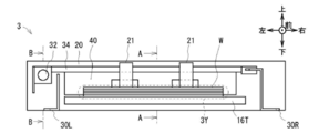
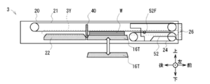
- FIG. 3B is a cross-sectional view taken along the line AA in FIG. 3A.
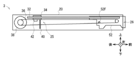
- FIG. 3B is a sectional view taken along the line BB in FIG. 3A.
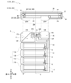
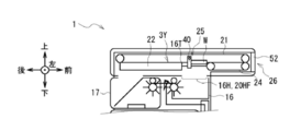
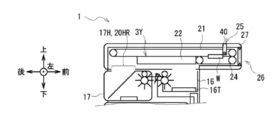
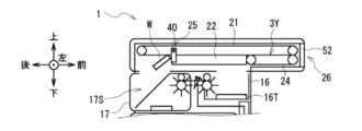
- FIGS. 1 and 2 show the configuration of banknote dispensing machine 1 in a state where the bundle transport unit 3 is detached from the storage unit 2 for convenience of explanation.
- the control unit 4 is mainly configured by a CPU (Central Processing Unit) (not shown), and reads and executes a predetermined program from a ROM (Read Only Memory), a flash memory, etc. (not shown), thereby performing a withdrawal process and the like. Process.
- the control unit 4 includes a storage unit including a RAM (Random Access Memory), a hard disk drive, a flash memory, and the like, and stores various information in the storage unit.
- the side of the banknote dispenser 1 facing the customer is the front side, the opposite is the rear side, the left and right are the left side and the right side as viewed from the customer facing the front side, and the upper side and the lower side. Is defined and explained.
- the storage unit 2 incorporates a plurality of portions for performing various processing relating to banknotes in a rectangular parallelepiped storage housing 10, stores banknotes, and stacks banknotes to be handed over to a user to collect banknote bundles. Generate.
- four banknote storages 11 11A, 11B, 11C, and 11D
- a transport unit 13 a discrimination unit 14
- a switching unit 15 a stacking unit 16, and a reject storage unit 17 are provided. Yes.
- the banknote storage 11 (11A, 11B, 11C, and 11D) as a medium storage is attached so as to be stacked from the center in the vertical direction on the rear side of the storage housing 10 to the lower side.
- Each banknote storage 11 is formed in a flat rectangular parallelepiped shape that is short in the vertical direction and long in the front-rear direction, and stores banknotes in a state in which the paper surface is lined up in the front-rear direction and in the front-rear direction. .
- a feeding section 12 for separating and feeding out the banknotes stored one by one is provided at the lower part on the front side of the banknote storage 11.
- Each banknote storage 11 is removed from the storage housing 10 by being pulled backward with respect to the storage housing 10, and is aligned with the storage housing 10 and pushed forward, Attached to the housing 10. That is, each banknote storage 11 is configured to be detachable from the rear surface of the storage housing 10. Moreover, each banknote storage 11 has a predetermined denomination of banknotes stored therein.
- the conveyance part 13 comprises the conveyance path which is a path
- the identification unit 14 is provided along the conveyance path of the conveyance unit 13 at the front side portion of the banknote storage 11 ⁇ / b> A in the conveyance unit 13.
- a plurality of types of sensors such as a thickness sensor and an image sensor are incorporated in the discrimination unit 14 and, based on information obtained from each sensor, discriminates the denomination and running state of a bill to be conveyed, The discrimination result is supplied to the control unit 4.
- the control part 4 determines the conveyance destination of each banknote based on the obtained discrimination result. Specifically, the control unit 4 sets the transport destination of normal banknotes to be withdrawn to the stacking unit 16, and the transport destination of banknotes that should not be withdrawn (hereinafter referred to as reject banknotes) to the reject storage 17. Decide each.
- the switching unit 15 is disposed substantially at the center in the front-rear direction on the upper side of the banknote storage 11 ⁇ / b> A. Based on the control of the control unit 4, a blade (shown by a triangle in the drawing) that abuts against the banknote and changes the traveling direction. By changing the inclination angle, the direction of travel of the banknote is switched.
- the switching unit 15 is connected to the lower discrimination unit 14, the front stacking unit 16, and the rear reject storage 17 by the transport unit 13.
- the switching unit 15 switches the traveling direction of each bill transported from below according to the transport destination determined by the control unit 4, and proceeds to the front stacking unit 16 or the rear reject storage 17.
- the stacking unit 16 is located on the uppermost front side in the housing 10 and forms a stacking space 16S that is a space for stacking banknotes.
- the stacking unit 16 has a stage 16T for stacking banknotes on the upper surface in the stacking space 16S.
- the stage 16T is formed in a thin plate shape in the up-down direction, and the lengths in the front-rear direction and the left-right direction are longer than the lengths of the short side and the long side of the bill, respectively.
- a discharge unit 16R that discharges the bills conveyed from the switching unit 15 into the stacking space 16S is provided on the upper rear side of the stacking unit 16. Therefore, the stacking unit 16 stacks the banknotes conveyed from the switching unit 15 and discharged into the stacking space 16S by the discharge unit 16R on the stage 16T. At this time, the banknotes accumulated on the stage 16T are stacked in a bundle. Therefore, hereinafter, the banknotes stacked in this way are also referred to as banknote bundles.
- the stage 16T moves up and down by a stage moving mechanism (not shown). Further, an accumulation hole 16H penetrating in the vertical direction is formed on the upper surface of the accumulation portion 16 over a range corresponding to the accumulation space 16S.
- the length of the accumulation hole 16H in the front-rear direction is slightly longer than the length of the stage 16T in the front-rear direction.
- the accumulation hole 16H also penetrates the upper surface of the storage housing 10 and communicates the accumulation space 16S with the space above the storage housing 10. For this reason, the stacking unit 16 moves the stage 16T upward while the banknote bundle is placed on the stage 16T, thereby lifting the stage 16T and the banknote bundle above the upper surface of the storage housing 10.
- the reject storage 17 is located on the uppermost rear side in the storage housing 10 and forms a storage space 17S for storing banknotes therein.
- the storage space 17S is partitioned into a rear upper side and a front lower side by a partition plate 17P. Further, on the upper front side of the reject storage 17, a discharge unit 17R that discharges the bills conveyed from the switching unit 15 into the storage space 17S is provided. For this reason, reject storage 17 stores the bill (namely, reject bill) conveyed from switching part 15 and discharge
- the upper surface of the reject storage 17 is provided with an intake hole 17H penetrating in the vertical direction over a range corresponding to the storage space 17S.
- the length in the front-rear direction in the intake hole 17H is substantially equal to the length in the front-rear direction in the accumulation hole 16H of the accumulation portion 16.
- the intake hole 17H also penetrates the upper surface of the storage housing 10 and communicates the storage space 17S with the space above the storage housing 10. For this reason, when the banknote falls from above, the reject storage 17 stores the banknote in the storage space 17S.
- reject storage 17 is removed from the storage case 10 by being pulled backward with respect to the storage case 10 in the same manner as the banknote storage 11 and is also aligned with the storage case 10 in the forward direction. By being pushed into the housing casing 10, it is mounted.
- the distance in the front-rear direction from the center line C to the accumulation hole 16H is the center line.
- the distance in the front-rear direction from C to the intake hole 17H is substantially the same. That is, the storage unit 2 has substantially the same length in the front-rear direction of the collecting hole 16H and the intake hole 17H, and the distance from the center line C is also substantially the same. It is formed symmetrically.
- the banknote dispensing machine 1 makes the withdrawal port 26 of the bundle transport unit 3 face the front side or the rear side, and aligns the accumulation hole 16H and the intake hole 17H with either the front passage hole 20HF or the rear passage hole 20HR.
- the banknote dispensing machine 1 By being attached to the storage unit 2, it can be assembled in two ways: a front machine with a withdrawal port 26 provided on the front side and a rear machine with a withdrawal port 26 provided on the rear side.
- the bundle transport unit 3 as a whole is formed in a flat rectangular parallelepiped shape that is short in the vertical direction and long in the front-rear direction, and the length in the front-rear direction is longer than that of the storage unit 2.
- the bundle conveyance unit 3 is provided with various mechanisms for conveying a banknote bundle in a rectangular parallelepiped bundle conveyance housing 20.
- An upper belt 21 is provided on the upper portion in the bundle transport housing 20.
- the upper belt 21 is an endless belt that is wound around rollers disposed in the vicinity of the rear end and the vicinity of the front end, and the lower surface travels along the front-rear direction as the roller rotates.
- the traveling direction of the lower surface portion of the upper belt 21 is regarded as the traveling direction of the upper belt 21.
- a large hole portion 20H (FIG. 2) that is a large hole is formed in a wide range from the lower center of the bundle conveyance housing 20 to the rear side in the front-rear direction.
- a sandwiching conveyance guide 22 is provided in a range of the large hole portion 20H in a portion below the upper belt 21 in the bundle conveyance housing 20.
- the nipping / conveying guide 22 is formed in a flat, rectangular parallelepiped shape that is thin in the vertical direction, and its upper surface is opposed to the lower surface of the upper belt 21.
- the nipping / conveying guide 22 is moved in the front-rear direction within the large hole portion 20H by a moving mechanism (not shown).
- a moving mechanism (not shown).
- the nipping / conveying guide 22 moves to the front side, the central hole and the front side of the large hole portion 20H are closed, and the rear side range is opened.
- the portion opened to the rear side at this time is referred to as a rear passage hole 20HR.
- the nipping / conveying guide 22 moves to the rear side, the vicinity of the center and the rear side of the large hole portion 20H are closed and the front side range is opened.
- the part opened to the front side at this time is referred to as a front passage hole 20HF.
- a lower belt 24 that is an endless belt is provided in the lower portion of the bundle transport housing 20 from the upper belt 21 and in front of the large hole portion 20H.
- the lower belt 24 is configured such that the upper belt 21 is cut in the front-rear direction, and the upper surface thereof is opposed to the lower surface of the upper belt 21 so as to run in the front-rear direction.
- the traveling direction of the upper surface portion of the lower belt 24 will be regarded as the traveling direction of the lower belt 24 below.
- the stage 16T of the stacking unit 16 moves upward in the front passage hole 20HF that is opened without being closed in the large hole part 20H. When it is done, it is closed by the stage 16T.
- a bundle conveyance path 3 ⁇ / b> Y sandwiched from above and below by the upper belt 21, the stage 16 ⁇ / b> T, the nipping and conveying guide 22, and the lower belt 24 is formed.
- a bundle conveyance frame 30L and a bundle conveyance frame 30R (hereinafter also referred to collectively as a bundle conveyance frame 30), which are metal plates fixed to the bundle conveyance housing 20, are respectively provided on the left side and the right side. Is provided. Further, on the left side of the bundle conveyance frame 30L, a cylindrical slide shaft 32 extending along the front-rear direction, which is the conveyance direction of the banknote bundle W, is fixed to the bundle conveyance frame 30L. On the upper side of the bundle conveying path 3Y, an extruding part frame 34 is provided in the left-right direction from the left outer side to the right outer side of the bundle conveying path 3Y. The pusher frame 34 is supported by being slidably inserted into the slide shaft 32 at the left end, and slidably supported by the bundle conveying frame 30R at the right end.
- an extrusion unit drive belt 36 as a drive mechanism is provided on the left side of the bundle conveyance frame 30L.
- the pusher drive belt 36 is an endless belt that is wound around rollers arranged in the vicinity of the rear end and in the vicinity of the front end so as to be in parallel with the slide shaft 32.
- an extrusion portion drive motor 38 as a drive source is fixed to the bundle conveying frame 30 behind the extrusion portion drive belt 36, and a driving force is transmitted to a roller behind the extrusion portion drive belt 36. To rotate the roller.
- the pushing portion driving belt 36 and the pushing portion driving motor 38 are not shown and are omitted.
- the extrusion unit drive belt 36 has an extrusion unit frame 34 of the extrusion unit 25 fixed thereto by a belt clamp 42.
- the extruding portion 25 includes an extruding portion frame 34 and an extruded plate 40.
- the extrusion plate 40 has a plate shape, and is provided so as to protrude downward from the extrusion unit frame 34 at a position located above the bundle conveyance path 3Y in the extrusion unit frame 34. A part of the extrusion plate 40 protrudes downward from the lower surface of the upper belt 21, and is moved along the front-rear direction, that is, along the bundle conveyance path 3Y by the driving force of the extrusion unit drive motor 38. .
- the pusher plate 40 moves in the dispensing direction (forward) together with the pusher frame 34 to push the rear end of the banknote bundle W while preventing the banknote bundle W from being misaligned or remaining, while the pusher frame 34
- the front end of the banknote bundle W is pushed while preventing the banknote bundle W from being misaligned or remaining behind the banknotes by moving in the take-in direction together with 34.
- the extrusion plate 40 is displaced in the vertical direction with respect to the extrusion unit frame 34 by a displacement mechanism (not shown). That is, as shown in FIG. 3B, the extruded plate 40 is displaced downward from the lower surface of the upper belt 21 as described later, in addition to lowering a part thereof below the lower surface of the upper belt 21.
- the extrusion plate 40 protrudes downward from the lower surface of the upper belt 21 at only a few discrete points in the left-right direction. Further, gaps or grooves along the front-rear direction are formed in the holding conveyance guide 22, the lower belt 24, and the stage 16 T of the stacking unit 16 in the storage unit 2 according to the extrusion plate 40. It is designed not to interfere. For this reason, when the banknote bundle W exists in the bundle conveyance path 3Y, the extrusion plate 40 pushes it forward and backward to advance it.
- a withdrawal port 26 is formed to deliver the banknote bundle W that has been conveyed forward in the bundle conveyance path 3Y to the user.
- a shutter 52 that opens or closes the dispensing port 26 with respect to the outside by rotating around the shutter fulcrum 52F is provided in the vicinity of the dispensing port 26.
- a withdrawal port sensor 27 for detecting the banknote bundle W is provided.
- the withdrawal port sensor 27 is an optical sensor configured by a combination of a light emitting element that emits predetermined detection light and a light receiving element that receives the detection light, and intersects the optical path of the detection light with the bundle conveyance path 3Y. Yes.
- the withdrawal port sensor 27 notifies the control unit 4 of the light reception result of the detection light.
- the control unit 4 determines whether or not there is a banknote bundle W at the withdrawal port 26 based on the light reception result.
- the banknote dispensing machine 1 protects banknotes stored therein by locking the shutter 52 in a state where the bank 26 is closed to the outside when the banknotes are not dispensed by the user. On the other hand, the banknote dispensing machine 1 releases the lock 52 and rotates the shutter 52 to open the dispensing port 26 to the outside during the dispensing operation for dispensing the banknote bundle W to the user. The banknote bundle W is withdrawn.
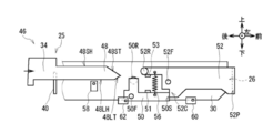
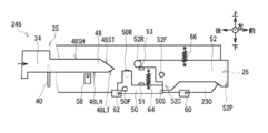
- the shutter opening / closing mechanism 46 mainly includes a lock lever 50 that latches on the shutter 52, and the lock lever 50. And the push-out portion frame 34 for releasing the lock and opening the shutter 52.
- a plate-like shutter opening / closing protrusion 48 that protrudes forward is formed at the front end portion of the extruded portion frame 34. Since the shutter opening / closing protrusion 48 is formed integrally with the pushing portion frame 34, the shutter opening / closing projection 48 reciprocates in the dispensing direction and the taking-in direction together with the pushing portion frame 34.
- the shutter opening / closing protrusion 48 is formed with a shutter holding horizontal plane 48SH which is a plane along the horizontal direction at the upper end surface, and a lock lever holding horizontal plane 48LH which is a plane along the horizontal direction at the lower end surface. From the front end of the shutter holding horizontal surface 48SH, a shutter turning inclined surface 48ST, which is a plane inclined downward as it goes forward, is upward from the front end of the lock lever holding horizontal surface 48LH as it goes forward. Lock lever rotation inclined surfaces 48LT, which are inclined planes, are respectively formed.
- shutter rotation inclined surface 48ST and the lock lever rotation inclined surface 48LT are collectively referred to as a shutter release member inclined surface
- the shutter holding horizontal surface 48SH and the lock lever holding horizontal surface 48LH are also collectively referred to as a shutter release member horizontal surface.
- the lock lever 50 is a substantially L-shaped member in a side view formed of a sheet metal, and is a non-rear position than a withdrawal position (FIG. 4D) that is a position when the banknote bundle W is dispensed. It is located below the front side of the shutter opening / closing protrusion 48 and below the rear side of the shutter 52 at the dispensing position (FIGS. 4A, 4B and 4C).
- a cylindrical lock lever fulcrum 50F fixed to the bundle conveyance frame 30 is inserted in the left-right direction.
- the lock lever 50 is configured to be pivotable clockwise and counterclockwise in FIG. 4 about the lock lever fulcrum 50F.
- the clockwise direction that is the unlocking direction is also referred to as the unlocking direction
- the counterclockwise direction that is the locking direction is also referred to as the locking direction.
- a lower end of a reset spring 56 which is a tension spring having an upper end attached to the shutter 52, is attached in front of the lock lever fulcrum 50F in the lock lever 50, so that the lock lever 50 is centered on the lock lever fulcrum 50F.
- a biasing force is applied in the locking direction.
- a lock lever limiter 51 fixed to the bundle conveyance frame 30 is provided on the upper side of the lock lever 50 in front of the lock lever fulcrum 50F.
- the lock lever limiter 51 abuts on the upper front side of the lock lever fulcrum 50F of the lock lever 50 in the locked state. For this reason, the lock lever 50 is urged in the locking direction by the urging force of the reset spring 56 in the locked state, and is brought into contact with the lock lever limiter 51 to prevent further rotation in the locking direction. Positioned at the pivot position. *
- a cylindrical lock lever roller 50R is rotatably attached to the upper right side of the lock lever fulcrum 50F in the lock lever 50.
- the lock lever roller 50R faces the lock lever rotation inclined surface 48LT in the front-rear direction so as to be at the same vertical position (height) as the lock lever rotation inclined surface 48LT of the shutter opening / closing protrusion 48.
- the lock lever 50 In the closed state and the locked state, the lock lever 50 has the rotation restricting portion 50S at the front end thereof on the rotation locus of the shutter 52, and the rotation restricting portion 50S contacts the contact portion 52C of the shutter 52.
- the contact prevents the shutter 52 from rotating in the opening direction. That is, when a force is applied in the opening direction to the shutter plate 52P of the shutter 52 in the closed state, a force directed rearward is transmitted from the contact portion 52C of the shutter plate 52P to the rotation restricting portion 50S of the lock lever 50.
- the lock lever fulcrum 50F is positioned behind the rotation restricting portion 50S, and the force directed backward from the rotation restricting portion 50S is applied to the lock lever fulcrum 50F, so the lock lever 50 does not rotate.
- a plate-like shutter plate 52P that is longer than the length of the dispensing port 26 in the left-right direction and the up-down direction is formed so as to cover the front side of the dispensing port 26.
- a cylindrical shutter fulcrum 52F fixed to the bundle conveying frame 30 is inserted in the left-right direction. Accordingly, the shutter 52 is configured to be rotatable clockwise and counterclockwise in FIG. 4 about the shutter fulcrum 52F.
- the clockwise direction which is the direction in which the withdrawal port 26 is opened
- the counterclockwise direction which is the direction in which the withdrawal port 26 is closed
- a reset spring 56 which is a tension spring with a lower end attached to the lock lever 50, is attached to the rear of the shutter fulcrum 52F in the shutter 52, so that the shutter 52 is closed in the closing direction around the shutter fulcrum 52F. A biasing force is applied.
- a shutter limiter 53 fixed to the bundle conveying frame 30 is provided below the shutter fulcrum 52F of the shutter 52.
- the shutter limiter 53 contacts the lower side of the shutter 52 behind the shutter fulcrum 52F in the closed state. For this reason, the shutter 52 is urged in the closing direction by the urging force of the reset spring 56 in the closed state, and is brought into contact with the shutter limiter 53, thereby preventing further rotation in the closing direction and a predetermined rotation. Positioned in position.
- a shutter roller 52R having a cylindrical shape is rotatably attached to the upper left side of the shutter 52 behind the shutter fulcrum 52F.
- the shutter roller 52R is opposed to the shutter rotation inclined surface 48ST in the front-rear direction so as to be at the same vertical position (height) as the shutter rotation inclined surface 48ST of the shutter opening / closing protrusion 48.
- an extrusion plate detection sensor 58 for detecting the extrusion unit frame 34 is provided.
- the push plate detection sensor 58 is a U-shaped optical sensor in which a light emitting portion that emits detection light and a light receiving portion that receives the detection light are arranged on the left and right sides with a groove through which the push portion frame 34 passes. is there.
- the extrusion plate detection sensor 58 notifies the control unit 4 of the light reception result of the detection light. Based on the light reception result, the control unit 4 determines whether or not the pusher plate 40 is in the dispensing position as the delivery position.
- a lock lever detection sensor 62 for detecting the lock lever 50 is provided on the movement path of the lock lever 50.
- the lock lever detection sensor 62 is an optical sensor similar to the push plate detection sensor 58.
- the lock lever detection sensor 62 notifies the control unit 4 of the detection light reception result.
- the control unit 4 determines whether or not the lock lever 50 is in a locked state based on the light reception result.
- a shutter detection sensor 60 for detecting the shutter 52 is provided on the movement path of the shutter 52.
- the shutter detection sensor 60 is an optical sensor similar to the push plate detection sensor 58.
- the shutter detection sensor 60 notifies the control unit 4 of the detection light reception result.
- the control unit 4 determines whether or not the shutter 52 is in an open state based on the light reception result.
- the banknote dispensing machine 1 transfers the banknote bundle W from the stacking unit 16 to the bundle transport unit 3 to run the upper belt 21 and also from the bundle transport path 3Y above the front passage hole 20HF to the withdrawal port 26.
- the bill bundle W is conveyed from the stage 16T in the withdrawal direction by moving the pusher 25 in the withdrawal direction, which is the forward direction along the horizontal direction, and is in the state shown in FIG. 4A. In this state, the pushing plate 40 is in the non-withdrawal position, the lock lever 50 is in the locked state, and the shutter 52 is in the closed state.
- the banknote bundle W is not shown and is omitted.
- the extrusion plate detection sensor 58 notifies the control unit 4 of a light reception result indicating that the detection light is received.
- the control unit 4 determines that the push plate 40 is at the non-withdrawal position based on the light reception result.
- the lock lever detection sensor 62 notifies the control unit 4 of a light reception result indicating that the detection light is not received.
- the control unit 4 determines that the lock lever 50 is in the locked state based on the light reception result.
- the shutter detection sensor 60 notifies the control unit 4 of a light reception result indicating that the detection light is received.
- the control unit 4 determines that the shutter 52 is in the closed state based on the light reception result.
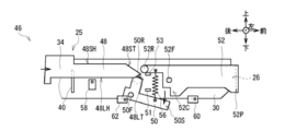
- the shutter 52 is in an unlocked state that does not prevent the shutter 52 from rotating in the opening direction.
- the lock lever detection sensor 62 notifies the control unit 4 of a light reception result indicating that the detection light is received.
- the control unit 4 determines that the lock lever 50 is in the unlocked state based on the light reception result.
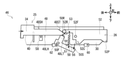
- the shutter rotation inclined surface 48ST of the shutter opening / closing protrusion 48 comes into contact with the shutter roller 52R of the shutter 52, as shown in FIG. 4C.
- the lock lever 50 rotates in the unlocking direction by moving the lock lever roller 50R downward while contacting the lock lever rotation inclined surface 48LT of the shutter opening / closing projection 48, and the lock lever roller 50R Dive into the lock lever holding horizontal plane 48LH.
- the shutter 52 moves upward while the shutter roller 52R is in contact with the shutter rotation inclined surface 48ST of the shutter opening / closing protrusion 48.
- the shutter roller 52R is moved up to the shutter holding horizontal surface 48SH.
- the shutter roller 52R comes into contact with the shutter holding horizontal surface 48SH of the shutter opening / closing protrusion 48, and the rotation in the closing direction is restricted.
- the shutter opening / closing protrusion 48 holds the shutter 52 in the open state.
- the shutter detection sensor 60 notifies the control unit 4 of a light reception result indicating that the detection light is not received.
- the control unit 4 determines that the shutter 52 is in the open state based on the light reception result.
- the lock lever 50 is urged in the locking direction by the urging force of the reset spring 56, while the lock lever roller 50R comes into contact with the lock lever holding horizontal surface 48LH of the shutter opening / closing projection 48, and the rotation in the locking direction is restricted. Is done. Thereby, the shutter opening / closing protrusion 48 holds the unlocked state of the lock lever 50.
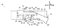
- the extrusion plate detection sensor 58 notifies the control unit 4 of a light reception result indicating that the detection light is not received.
- the control unit 4 determines that the push plate 40 is at the dispensing position based on the light reception result.
- the control unit 4 stops the movement of the extrusion unit 25 and causes the upper belt 21 and the lower belt 24 (FIGS. 1 and 2) to travel forward.
- the banknote bundle W is advanced forward along the bundle conveyance path 3Y, a part of the banknote bundle W is exposed from the dispensing port 26, and the upper belt 21 and the lower belt 24 sandwich the vicinity of the rear end of the banknote bundle W.
- the user takes out the banknote bundle W.
- the banknote dispenser 1 performs the shutter opening operation of shifting the lock lever 50 in the locked state to the unlocked state and shifting the shutter 52 in the closed state to the open state.
- the banknote dispensing machine 1 moves horizontally from the state shown in FIG. 4D to the bundle conveyance path 3Y above the rear passage hole 20HR and the front passage hole 20HF from the withdrawal port 26.
- the shutter opening / closing projection 48 is first removed from the shutter 52, and the shutter 52 is rotated to close it, and the pusher 25 is further removed.
- the shutter is opened and closed, and the shutter opening / closing projection 48 is removed from the lock lever 50 and the lock lever 50 is rotated to obtain a locked state. That is, the banknote dispenser 1 performs an operation opposite to the shutter opening operation described above, and performs a shutter closing operation that shifts the opened shutter 52 to the closed state and shifts the unlocked lock lever 50 to the locked state. Do.
- control unit 4 first moves the stage 16T downward, and moves the clamping conveyance guide 22 forward to close the accumulation hole 16H and the front passage hole 20HF of the accumulation unit 16. Moreover, the control part 4 moves the extrusion board 40 to the backmost side.
- the control unit 4 sequentially feeds the banknotes of the denomination and the number corresponding to the withdrawal amount from the banknote storage 11 by the feeding unit 12, transports it upward by the transporting unit 13, and makes it discriminate by the discrimination unit 14.
- the control unit 4 determines the transport destination as the stacking unit 16 or the reject storage 17 according to whether or not the banknote can be withdrawn.
- the control unit 4 conveys the banknotes identified by the identification unit 14 backward and upward by the conveyance unit 13 to reach the switching unit 15.
- the switching unit 15 switches the advancing direction according to the transport destination determined for each bill, and advances the stacking unit 16 or the reject storage case 17.
- the stacking unit 16 discharges the conveyed banknotes into the stacking space 16S by the discharge unit 16R and stacks it on the stage 16T. At this time, the stacking portion 16 is closed on the upper side of the stacking hole 16H by the nipping and conveying guide 22, so that banknotes released from the discharge portion 16R are prevented from rising upward and are stably stacked on the stage 16T. . Further, the reject storage 17 discharges and stores the conveyed banknote into the storage space 17S by the discharge unit 17R. *
- the control unit 4 sequentially counts the denominations and the number of banknotes collected in the stacking unit 16, that is, the banknotes stacked in the stacking unit 16. 11 cancels the feeding of banknotes. As a result, on the stage 16T of the stacking unit 16, a banknote bundle W in which banknotes to be withdrawn are stacked in a bundle is placed.
- the control unit 4 opens the accumulation hole 16H and the front passage hole 20HF of the accumulation unit 16 by moving the holding conveyance guide 22 backward, and then moves the stage 16T of the accumulation unit 16 to the stage 16T.
- the banknote bundle W is lifted by moving it upward.
- the control unit 4 aligns the upper surface of the stage 16T with the same height as the upper surface of the holding and conveying guide 22, and configures a part of the bundle conveying path 3Y by the stage 16T, and the banknote bundle on the stage 16T. W is positioned in the bundle conveyance path 3Y.
- control unit 4 moves the banknote bundle W forward along the bundle transport path 3Y by moving the upper belt 21 and the lower belt 24 forward and moving the push plate 40 forward.
- the shutter opening / closing projection 48 (FIG. 4) of the push-out portion 25 brings the lock lever 50 into the unlocked state and opens the shutter 52.
- the control unit 4 detects that the banknote bundle W has reached the withdrawal port 26 based on the notification from the withdrawal port sensor 27, the control unit 4 causes the upper belt 21 and the lower belt 24 to travel as shown in FIG. 5C. Stop.
- the control part 4 moves the stage 16T below at this time, and complete
- the banknote dispenser 1 exposes a part of the banknote bundle W from the withdrawal port 26 and holds the vicinity of the rear end of the banknote bundle W by the upper belt 21 and the lower belt 24 to the user. This banknote bundle W can be taken out.
- control unit 4 monitors whether or not the banknote bundle W has been taken out from the withdrawal port 26 based on the notification from the withdrawal port sensor 27, and a predetermined standby time (for example, 30 seconds) has elapsed. If it is not taken out, the taking-in operation for taking in the banknote bundle W is started.
- a predetermined standby time for example, 30 seconds
- the control unit 4 first opens the rear passage hole 20HR and the intake hole 17H by moving the clamping conveyance guide 22 forward. Subsequently, the control unit 4 moves the upper belt 21 and the lower belt 24 backward while displacing the extrusion plate 40 upward, thereby taking the banknote bundle W into the bundle conveyance path 3Y, and the bundle conveyance path 3Y. Proceed backwards along. At this time, when the control unit 4 detects that the banknote bundle W has reached the rear side of the extrusion plate 40 by a sensor (not shown), the control unit 4 displaces the extrusion plate 40 downward and moves it backward to move the banknote bundle W. Assists backward transport.
- the control unit 4 drops the banknote bundle W from the bundle transport path 3Y, and the storage space of the reject storage 17 It is stored in 17S and the take-in operation is terminated.
- the banknote dispenser 1 takes in the banknote bundle W that the user has forgotten to remove from the withdrawal port 26 and stores it in the reject storage 17.
- the lock lever 50 uses the operation of the pushing unit 25 that moves in the withdrawal direction while pushing the rear end of the banknote bundle W with the push-out plate 40. Can be unlocked and the shutter 52 can be opened.
- the banknote dispenser 1 When closing the opened shutter 52, the banknote dispenser 1, after withdrawing the banknote bundle W, moves the pushing part 25 in the take-in direction from the withdrawal position to first remove the shutter opening / closing projection 48 from the shutter 52.
- the shutter 52 is turned to be in a closed state.
- the banknote dispensing machine 1 is further brought into the locked state by moving the pushing portion 25 in the take-in direction to remove the shutter opening / closing projection 48 from the lock lever 50 and rotating the lock lever 50.
- the banknote dispensing machine 1 uses the operation of the push-out portion 25 that moves in the take-in direction from the withdrawal port 26 after dispensing the banknote bundle W, and closes the shutter 52 and turns the lock lever 50 on. It can be in a locked state.
- the banknote dispensing machine 1 is provided with a dedicated drive source for driving the shutter 52 that opens or closes the dispensing port 26 and a dedicated drive source for driving the lock lever 50 that keeps the shutter 52 closed.
- the opening / closing operation of the shutter 52 can be performed using the pushing portion 25 originally provided in the banknote dispensing machine 1 in order to withdraw the banknote bundle W, and the configuration can be simplified. It can be cheaper.
- the banknote dispensing machine 1 stores a space for mounting an actuator that is a driving source for driving a shutter 52 that opens or closes the dispensing port 26 and an actuator that is a driving source for driving the lock lever 50. Since there is no need to provide the inside of the banknote dispenser 1, the bill dispenser 1 can be downsized.
- the banknote dispensing machine 1 can close or open the withdrawal port 26 for delivering the banknote bundle W, which is a bundle of sheets on which paper-like media are stacked, to the user, and the withdrawal port 26.
- the provided shutter, the holding conveyance guide 22 and the stage 16T for guiding the banknote bundle W, and the withdrawal port 26 are arranged so as to face the holding conveyance guide 22 and the stage 16T and are in contact with one end side of the banknote bundle W.
- the pusher plate 40 moves toward the withdrawal port 26, the pusher plate 40 moves together with the pusher plate 40, and the withdrawal plate 40 moves to the withdrawal port 26.
- a shutter opening / closing protrusion 48 for moving the shutter 52 in the opening direction for opening the mouth 26 is provided.
- the banknote dispenser 1 uses the driving force of the pushing portion driving motor 38 without providing a driving source for opening and closing the shutter 52 separately from the pushing portion driving motor 38 that is a driving source for driving the pushing portion 25.
- the shutter 52 can be opened and closed.
- the banknote dispensing machine 101 according to the second embodiment has a bundle conveyance unit 103 and a bundle conveyance unit 3 as compared with the banknote dispensing machine 1 according to the first embodiment. Although different, other configurations are the same.
- the shutter opening / closing mechanism 146 according to the second embodiment is configured such that the shutter opening / closing mechanism 46 according to the first embodiment is substantially vertically inverted.
- a plate-like shutter opening / closing protrusion 148 that protrudes forward is formed at the front end of the extruded portion frame 134.
- the shutter opening / closing protrusion 148 is formed with a shutter holding horizontal plane 148SH which is a plane along the horizontal direction at the lower end surface, and a lock lever holding horizontal plane 148LH which is a plane along the horizontal direction at the upper end surface.
- a shutter turning inclined surface 148ST which is a plane inclined upward as it goes forward, is downward from the front end of the lock lever holding horizontal surface 148LH as it goes forward.
- Lock lever rotation inclined surfaces 148LT which are inclined planes, are respectively formed.
- the lock lever 150 is located above the front side of the shutter opening / closing projection 148 at the non-withdrawal position (FIGS. 7A, 7B, and 7C), which is the rear side of the withdrawal position (FIG. 7D) and the rear side of the shutter 152. Is located above.
- a cylindrical lock lever fulcrum 150F fixed to the bundle conveyance frame 130 is inserted in the left-right direction.
- the lock lever 150 is configured to be pivotable clockwise and counterclockwise in FIG. 7 about the lock lever fulcrum 150F.
- the counterclockwise direction that is the unlocking direction in the rotation of the lock lever 150 is also referred to as the unlocking direction
- the clockwise direction that is the locking direction is also referred to as the locking direction.
- a reset spring 156 that is a tension spring having a lower end attached to the shutter 152 is attached in front of the lock lever fulcrum 150F of the lock lever 150, so that the lock lever 150 is centered on the lock lever fulcrum 150F. A biasing force is applied in the locking direction.
- a lock lever limiter 151 fixed to the bundle transport frame 130 is provided on the lower side of the lock lever 150 in front of the lock lever fulcrum 150F.
- the lock lever limiter 151 contacts the lower side of the lock lever 150 in front of the lock lever fulcrum 150F in the locked state. For this reason, the lock lever 150 is urged in the locking direction by the urging force of the reset spring 156 in the locked state, and abuts against the lock lever limiter 151 to prevent the lock lever 150 from rotating further in the locking direction. Positioned at the moving position.
- a cylindrical lock lever roller 150R is rotatably attached to the lower right side of the lock lever fulcrum 150F of the lock lever 150.
- the lock lever roller 150R faces the lock lever rotation inclined surface 148LT in the front-rear direction so that the lock lever roller 150R has the same vertical position (height) as the lock lever rotation inclination surface 148LT of the shutter opening / closing protrusion 148.
- the lock lever 150 In the closed state and the locked state, the lock lever 150 has the rotation restricting portion 150S at the front end thereof entering the rotation locus of the shutter 152, and the rotation restricting portion 150S contacts the contact portion 152C of the shutter 152. The contact prevents the shutter 152 from rotating in the opening direction.
- a plate-like shutter plate 152P that is longer than the length of the dispensing port 26 in the left-right direction and the up-down direction is formed so as to cover the front side of the dispensing port 26.
- a cylindrical shutter fulcrum 152F fixed to the bundle conveying frame 130 is inserted in the left-right direction. Accordingly, the shutter 152 is configured to be rotatable clockwise and counterclockwise in FIG. 7 about the shutter fulcrum 152F.
- the counterclockwise direction that is the direction in which the dispensing port 26 is opened is also referred to as the opening direction
- the clockwise direction that is the direction in which the dispensing port 26 is closed is also referred to as the closing direction.
- a reset spring 156 which is a tension spring attached to the lock lever 150, is attached to the rear of the shutter fulcrum 152F of the shutter 152, so that the shutter 152 moves in the closing direction with the shutter fulcrum 152F as a center. A biasing force is applied.
- a shutter limiter 153 fixed to the bundle conveying frame 130 is provided on the upper side of the shutter 152 behind the shutter fulcrum 152F.
- the shutter limiter 153 abuts on the upper side of the shutter 152 behind the shutter fulcrum 152F in the closed state. For this reason, the shutter 152 is urged in the closing direction by the urging force of the reset spring 156 in the locked state, and abuts against the shutter limiter 153 to prevent further rotation in the closing direction. Positioned in position.
- a cylindrical shutter roller 152R is rotatably mounted on the lower left side of the shutter 152 behind the shutter fulcrum 152F.
- the shutter roller 152R is opposed to the shutter rotation inclined surface 148ST in the front-rear direction so as to be at the same vertical position (height) as the shutter rotation inclined surface 148ST of the shutter opening / closing protrusion 148.
- an extrusion plate detection sensor 58 for detecting the extrusion unit frame 134 is provided.
- a lock lever detection sensor 162 for detecting the lock lever 150 is provided on the movement path of the lock lever 150.
- the lock lever detection sensor 162 is an optical sensor similar to the push plate detection sensor 58.
- the lock lever detection sensor 162 notifies the control unit 4 of the light reception result of the detection light.
- the control unit 4 determines whether or not the lock lever 150 is in a locked state based on the light reception result.
- a shutter detection sensor 160 that detects the shutter 152 is provided on the movement path of the shutter 152.
- the shutter detection sensor 160 is an optical sensor similar to the push plate detection sensor 58.
- the shutter detection sensor 160 notifies the control unit 4 of the detection light reception result.
- the control unit 4 determines whether or not the shutter 152 is in an open state based on the light reception result.
- the banknote dispensing machine 101 transfers the banknote bundle W from the stacking unit 16 to the bundle transport unit 103, travels the upper belt 21 and moves the pushing unit 125 in the withdrawal direction, thereby removing the banknote bundle W from the stage 16T. It is transported in the withdrawal direction to the state shown in FIG. 7A. In this state, the extrusion plate 40 is in the non-withdrawal position, the lock lever 150 is in the locked state, and the shutter 152 is in the closed state. In FIG. 7, the banknote bundle W is not shown and is omitted.
- the extrusion plate detection sensor 58 notifies the control unit 4 of a light reception result indicating that the detection light is received.
- the control unit 4 determines that the push plate 40 is at the non-withdrawal position based on the light reception result.
- the lock lever detection sensor 162 notifies the control unit 4 of a light reception result indicating that the detection light is not received.
- the control unit 4 determines that the lock lever 150 is in the locked state based on the light reception result.
- the shutter detection sensor 160 notifies the control unit 4 of a light reception result indicating that the detection light is received.
- the control unit 4 determines that the shutter 152 is in the closed state based on the light reception result.
- the lock lever 150 moves away from the rotation locus of the shutter 152 in the opening direction of the shutter 152 when the rotation restriction portion 150S moves above the contact portion 152C of the shutter 152, A non-locked state that does not hinder the rotation of the shutter 152 in the opening direction is obtained.
- the lock lever detection sensor 162 notifies the control unit 4 of a light reception result indicating that the detection light is received.
- the control unit 4 determines that the lock lever 150 is in an unlocked state based on the light reception result.
- the shutter rotation inclined surface 148ST of the shutter opening / closing protrusion 148 comes into contact with the shutter roller 152R of the shutter 152, as shown in FIG. 7C.
- the lock lever 150 rotates in the unlocking direction when the lock lever roller 150R moves upward while contacting the lock lever rotation inclined surface 148LT of the shutter opening / closing projection 148, and the lock lever roller 150R is locked. Take the lever holding horizontal surface 148LH.
- the shutter 152 moves downward while the shutter roller 152R is in contact with the shutter rotation inclined surface 148ST of the shutter opening / closing protrusion 148. , The shutter roller 152R enters the shutter holding horizontal surface 148SH. At this time, while the shutter 152 is urged in the closing direction by the urging force of the reset spring 156, the shutter roller 152R comes into contact with the shutter holding horizontal surface 148SH of the shutter opening / closing projection 148, and the rotation in the closing direction is restricted. As a result, the shutter opening / closing protrusion 148 holds the shutter 152 in the open state. In this state, the shutter detection sensor 160 notifies the control unit 4 of a light reception result indicating that the detection light is not received. The control unit 4 determines that the shutter 152 is in the open state based on the light reception result.
- the lock lever roller 150R comes into contact with the lock lever holding horizontal surface 148LH of the shutter opening / closing protrusion 148, and the rotation in the locking direction is restricted. Is done. As a result, the shutter opening / closing protrusion 148 maintains the unlocked state of the lock lever 150.
- the extrusion plate detection sensor 58 notifies the control unit 4 of a light reception result indicating that the detection light is not received.
- the control unit 4 determines that the push plate 40 is at the dispensing position based on the light reception result.
- the control unit 4 stops the movement of the extrusion unit 125 and causes the upper belt 21 and the lower belt 24 to travel forward, whereby the banknote bundle W is bundled. 3Y is advanced forward, a part of the banknote bundle W is exposed from the withdrawal port 26, and the vicinity of the rear end of the banknote bundle W is sandwiched between the upper belt 21 and the lower belt 24.
- the banknote bundle W is taken out.
- the banknote dispenser 101 performs the shutter opening operation of shifting the lock lever 150 in the locked state to the unlocked state and shifting the shutter 152 in the closed state to the open state.
- the banknote dispenser 101 when closing the shutter 152 in the open state, the banknote dispenser 101 first removes the shutter opening / closing projection 148 from the shutter 152 by moving the push-out portion 125 in the take-in direction from the state shown in FIG. 7D. By rotating 152, the closed state is set, and the pushing portion 125 is moved in the taking-in direction to release the shutter opening / closing projection 148 from the lock lever 150, and the lock lever 150 is turned to be in the locked state. That is, the banknote dispenser 101 performs an operation opposite to the shutter opening operation described above, and performs a shutter closing operation for shifting the shutter 152 in the open state to the closed state and the lock lever 150 in the unlocked state to the locked state. Do.
- the pushing portion 125 is moved in the withdrawal direction, and the shutter opening / closing projection 148 is first brought into contact with the lock lever 150 to rotate the lock lever 150.
- the rotation restricting portion 150S of the lock lever 150 is moved above the contact portion 152C of the shutter 152 to be in an unlocked state, and the pushing portion 125 is further moved in the dispensing direction so that the shutter opening / closing protrusion 148 is moved to the shutter 152.
- the shutter plate 152P is moved to the upper side of the dispensing port 26 to be opened by rotating the shutter 152.
- the banknote dispensing machine 201 according to the third embodiment has a bundle conveyance unit 203 and a bundle conveyance unit 3 as compared with the banknote dispensing machine 1 according to the first embodiment. Although different, other configurations are the same.
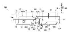
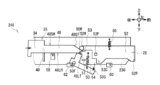
- the shutter opening / closing mechanism 246 according to the third embodiment has a lock lever reset spring instead of the reset spring 56 as compared with the shutter opening / closing mechanism 46 according to the first embodiment. 64 and the shutter reset spring 66 are different, but the other configuration is the same.
- the lower end of the lock lever reset spring 64 which is a tension spring attached to the bundle conveying frame 230, is attached to the lock lever 50.
- a biasing force is applied in the locking direction as the center. While the lock lever 50 is urged in the locking direction by the urging force of the lock lever reset spring 64 in the locked state, the lock lever 50 abuts against the lock lever limiter 51 to prevent further rotation in the locking direction. Positioned at the pivot position.
- a shutter reset spring 66 which is a tension spring attached to the bundle conveyance frame 230, is attached to the shutter 52 so that the shutter 52 is in the closing direction with the shutter fulcrum 52F as the center.
- a biasing force is applied. While the shutter 52 is urged in the closing direction by the urging force of the shutter reset spring 66 in the closed state, the shutter 52 abuts against the shutter limiter 53, thereby preventing further rotation in the closing direction and a predetermined rotation position. Is positioned.
- the banknote dispensing machine 201 first moves the pusher 25 in the dispensing direction when the banknote bundle is dispensed, and first locks the shutter opening / closing projection 48 as shown in FIG. 8B.
- the rotation restricting portion 50S of the lock lever 50 is moved below the contact portion 52C of the shutter 52 to be in the unlocked state, and further the pushing portion.
- the shutter plate 52P is moved as shown in FIG. 8D by moving the shutter 25 in the withdrawal direction and causing the shutter opening / closing projection 48 to contact the shutter 52 as shown in FIG. Is moved below the dispensing port 26 to be in an open state.
- the lock lever 50 and the shutter 52 are rotated by the shutter opening / closing protrusion 48 formed integrally with the pushing portion 25 .
- the present invention is not limited to this.
- the lock lever 50 and the shutter 52 are rotated by shutter opening / closing protrusions that are fixed to the pusher drive belt 36 separately from the pusher 25 and move as the pusher drive belt 36 rotates. It may be moved.
- the lock lever 50 and the shutter 52 may be rotated by a member that moves together with the pushing portion 25 as the pushing portion drive belt 36 rotates.
- the lock lever reset spring 64 and the shutter reset spring 66 of the shutter opening / closing mechanism 246 according to the third embodiment are applied in place of the reset spring 156 of the shutter opening / closing mechanism 146. Also good.
- the present invention is applied to the banknote dispensing machine 1 which is a front machine provided with the withdrawal port 26 on the front side.
- the present invention is not limited to this, and the storage unit is configured so that the bundle conveying unit 3 is in the front-rear direction opposite to the banknote dispensing machine 1, and the collecting holes 16H and the intake holes 17H are aligned with the rear passage holes 20HR and the front passage holes 20HF, respectively.
- the present invention may be applied to a banknote dispensing machine that is a rear surface machine that is attached to 2 and has a withdrawal port 26 provided on the rear side. The same applies to the second and third embodiments.
- the extruded plate 40 is plate-shaped.
- the present invention is not limited to this, and may have various shapes that can convey the banknote bundle W.
- the present invention is applied to the rotating shutters 52 and 152 .
- the present invention is not limited to this, and the present invention may be applied to a shutter that reciprocates in the vertical direction.
- the present invention is not limited to this, and may be applied to various devices that store paper-like media such as various kinds of cash vouchers, securities, or various tickets and deliver them to the user.
- the second and third embodiments are examples of devices that store paper-like media.
- the present invention is not limited to the above-described embodiments and other embodiments. That is, the scope of the present invention extends to embodiments in which some or all of the above-described embodiments and other embodiments described above are arbitrarily combined, and embodiments in which some are extracted. It is.
- the dispensing port 26 as a delivery port, the shutter 52 as a shutter, the sandwiching conveyance guide 22 and the stage 16T as a conveyance guide, and the extrusion plate 40 as a conveyance member has been described.
- the present invention is not limited to this, and a medium delivery device may be configured by a delivery port, a shutter, a conveyance guide, a conveyance member, and a shutter opening member having various other configurations. The same applies to the second and third embodiments.
- the shutter opening / closing mechanism 46 as the shutter opening / closing mechanism is configured by the push-out plate 40 as the conveying member and the shutter opening / closing protrusion 48 as the shutter opening member has been described.
- the present invention is not limited to this, and the shutter opening / closing mechanism may be configured by a conveyance member having various other configurations and a shutter opening member. The same applies to the second and third embodiments.
- the present invention can also be used in a banknote dispensing machine that stores banknotes in, for example, a detachable banknote storage and withdraws these banknotes in accordance with user operations.
Landscapes
- Physics & Mathematics (AREA)
- General Physics & Mathematics (AREA)
- Engineering & Computer Science (AREA)
- Mechanical Engineering (AREA)
- Business, Economics & Management (AREA)
- Accounting & Taxation (AREA)
- Finance (AREA)
- Pile Receivers (AREA)
- Discharge By Other Means (AREA)
Abstract
Description
[1-1.紙幣出金機の構成]
図1及び図2に示すように、第1の実施の形態による紙幣出金機1は、例えば金融機関等に設置され、利用者(すなわち金融機関の顧客)の操作に応じて紙幣を出金する。この紙幣出金機1は、大きく分けて下側の収納ユニット2及び上側の束搬送ユニット3により構成されており、さらに全体を制御する制御部4が組み込まれている。この紙幣出金機1は、その製造時に、下側の収納ユニット2に上側の束搬送ユニット3が取り付けられることにより組み立てられる。図2は説明の都合上、束搬送ユニット3が収納ユニット2から外れた状態の紙幣出金機1の構成を示している。
収納ユニット2は、直方体状の収納筐体10内に、紙幣に関する種々の処理を行う複数の部分が組み込まれており、紙幣を収納すると共に、利用者に引き渡すべき紙幣を集積して紙幣束を生成する。この収納筐体10内には、4個の紙幣収納庫11(11A、11B、11C及び11D)、搬送部13、鑑別部14、切替部15、集積部16及びリジェクト収納庫17が設けられている。
図3に示すように束搬送ユニット3は、全体として、上下方向に短く前後方向に長い、扁平な直方体状に形成されており、前後方向の長さが収納ユニット2よりも長くなっている。束搬送ユニット3は、直方体状の束搬送筐体20内に、紙幣束を搬送するための種々の機構が設けられている。
ロック部材としてのロックレバー50がシャッタ52に掛止しているロック状態を図4Aに示すように、シャッタ開閉機構46は、主に、シャッタ52に掛止するロックレバー50と、該ロックレバー50に当接しロックを解除すると共にシャッタ52を開放する押出部フレーム34とにより構成されている。
紙幣出金機1(図1)は、紙幣束Wを集積部16から束搬送ユニット3へ受け渡し、上ベルト21を走行させると共に、前通過孔20HFの上部の束搬送路3Yから出金口26へ水平方向に沿って向かう前方向である出金方向へ押出部25を移動させることにより、該紙幣束Wをステージ16Tから出金方向へ搬送し、図4Aに示す状態にする。この状態においては、押出板40が非出金位置に、ロックレバー50がロック状態に、シャッタ52が閉鎖状態になっている。なお図4において紙幣束Wは図示せず省略する。
次に、紙幣出金機1における出金に関する動作について説明する。紙幣出金機1は、図示しない操作部により利用者から出金の指示及び出金額を受け付けると、制御部4の制御に基づき、制御プログラム等を読み出して実行することにより、その構成に応じた処理を開始する。
以上の構成において、紙幣出金機1は、紙幣束Wを出金する際に押出部25を出金方向へ移動させシャッタ開閉突起48をまずロックレバー50に当接させ該ロックレバー50を回動させることにより、ロックレバー50の回動規制部50Sをシャッタ52の当接部52Cよりも下側へ移動させて非ロック状態とし、さらに押出部25を出金方向へ移動させシャッタ開閉突起48をシャッタ52に当接させ該シャッタ52を回動させることにより、シャッタ板52Pを出金口26よりも下側へ移動させて開放状態とするようにした。
[2-1.紙幣出金機及び束搬送ユニットの構成]
図1及び図2に示すように、第2の実施の形態による紙幣出金機101は、第1の実施の形態による紙幣出金機1と比べて、束搬送ユニット103が束搬送ユニット3と異なっているものの、それ以外は同様に構成されている。
図4と対応する図7に示すように、第2の実施の形態によるシャッタ開閉機構146は、第1の実施の形態によるシャッタ開閉機構46がほぼ上下反転したような構成となっている。
紙幣出金機101は、紙幣束Wを集積部16から束搬送ユニット103へ受け渡し、上ベルト21を走行させると共に出金方向へ押出部125を移動させることにより、該紙幣束Wをステージ16Tから出金方向へ搬送し、図7Aに示す状態にする。この状態においては、押出板40が非出金位置に、ロックレバー150がロック状態に、シャッタ152が閉鎖状態になっている。なお図7において紙幣束Wは図示せず省略する。
[3-1.紙幣出金機及び束搬送ユニットの構成]
図1及び図2に示すように、第3の実施の形態による紙幣出金機201は、第1の実施の形態による紙幣出金機1と比べて、束搬送ユニット203が束搬送ユニット3と異なっているものの、それ以外は同様に構成されている。
図4と対応する図8に示すように、第3の実施の形態によるシャッタ開閉機構246は、第1の実施の形態によるシャッタ開閉機構46と比べて、リセットスプリング56に代えてロックレバーリセットスプリング64及びシャッタリセットスプリング66が設けられている点が異なっているものの、それ以外は同様に構成されている。
紙幣出金機201は、紙幣出金機1と同様に、紙幣束を出金する際に押出部25を出金方向へ移動させシャッタ開閉突起48を図8(B)に示すようにまずロックレバー50に当接させ該ロックレバー50を回動させることにより、ロックレバー50の回動規制部50Sをシャッタ52の当接部52Cよりも下側へ移動させて非ロック状態とし、さらに押出部25を出金方向へ移動させシャッタ開閉突起48を図8(C)に示すようにシャッタ52に当接させ該シャッタ52を回動させることにより、図8(D)に示すようにシャッタ板52Pを出金口26よりも下側へ移動させて開放状態とする。
なお上述した第1の実施の形態においては、押出部25と一体に形成されたシャッタ開閉突起48でロックレバー50及びシャッタ52を回動させる場合について述べた。本発明はこれに限らず、例えば押出部25とは別個に押出部駆動ベルト36に固定され該押出部駆動ベルト36の回転移動に伴って移動するシャッタ開閉突起でロックレバー50及びシャッタ52を回動させても良い。要は、紙幣束Wを出金する際に押出部駆動ベルト36の回転移動に伴って押出部25と共に移動する部材によりロックレバー50及びシャッタ52を回動させれば良い。
Claims (13)
- 紙葉状の媒体が重ねられた媒体束を利用者に引き渡す引渡口と、
前記引渡口を閉鎖又は開放可能に設けられたシャッタと、
前記媒体束を案内する搬送ガイドと、
前記搬送ガイドに対向して配置され、前記媒体束の一端側と接触しながら前記引渡口へ向かう引渡方向へ移動し前記媒体束を前記引渡口へ向かって搬送する搬送部材と、
前記搬送部材が前記引渡口へ向かって移動する際、該搬送部材と共に移動し、前記引渡
口を開放させる開放方向へ前記シャッタを移動させるシャッタ開放部材と
を有する媒体引渡装置。 - 駆動力を発生させる駆動源と、
前記駆動源により駆動し前記搬送部材と前記シャッタ開放部材とを共に移動させる駆動機構と
をさらに有する請求項1に記載の媒体引渡装置。 - 前記搬送部材と前記シャッタ開放部材とは一体に形成されている
請求項2に記載の媒体引渡装置。 - 前記引渡口が閉鎖された閉鎖状態において前記シャッタに掛止することにより前記シャッタの前記開放方向への移動を規制するロック状態となると共に、前記閉鎖状態から、前記引渡口が開放された開放状態へ前記シャッタを移動させる際、前記シャッタから外れ非ロック状態となるロック部材をさらに有し、
前記シャッタ開放部材は、前記引渡方向へ移動し前記ロック部材に当接して前記非ロック状態にした後、さらに前記引渡方向へ移動し前記シャッタに当接して引渡位置まで移動し前記開放状態とする
請求項1に記載の媒体引渡装置。 - 前記シャッタ開放部材は、前記引渡位置から、前記引渡方向とは逆方向の取込方向へ移動し前記シャッタから外れて前記閉鎖状態とした後、さらに前記取込方向へ移動し前記ロック部材から外れて前記ロック状態とする
請求項4に記載の媒体引渡装置。 - 前記シャッタ開放部材は、前記引渡口側において、前記引渡方向に対し傾斜するシャッタ開放部材傾斜面が形成され、前記シャッタ開放部材傾斜面が前記ロック部材に当接して前記非ロック状態にした後、さらに前記引渡方向へ移動し前記シャッタ開放部材傾斜面が前記シャッタに当接して前記シャッタを前記ロック部材と同じ方向へ移動させ前記開放状態とする
請求項4に記載の媒体引渡装置。 - 前記シャッタ開放部材は、前記シャッタ開放部材傾斜面よりも前記引渡口とは逆側において、前記引渡方向に沿うシャッタ開放部材水平面が形成され、前記シャッタ開放部材傾斜面が前記ロック部材に当接して前記非ロック状態にした後に前記シャッタ開放部材水平面が前記ロック部材に当接して該ロック部材の前記非ロック状態を保持し、さらに前記引渡方向へ移動し前記シャッタ開放部材傾斜面が前記シャッタに当接して前記シャッタを前記開放状態とした後に前記シャッタ開放部材水平面が前記シャッタに当接して該シャッタの前記開放状態を保持する
請求項6に記載の媒体引渡装置。 - 前記ロック部材は、回転自在なロック部材ローラが設けられると共に所定のロック部材支点を軸に回動し、
前記シャッタ開放部材傾斜面は、前記引渡方向に対し、前記媒体束の幅方向と前記引渡方向とに直交する上下方向のうちの一方へ傾斜し前記ロック部材ローラに当接するロック部材回動傾斜面と、前記上下方向のうちの前記ロック部材回動傾斜面とは逆方向へ傾斜し前記シャッタに当接するシャッタ回動傾斜面とにより構成される
請求項7に記載の媒体引渡装置。 - 前記シャッタは、回転自在なシャッタローラが設けられると共に所定のシャッタ支点を軸に回動し、
前記シャッタ開放部材は、前記シャッタ回動傾斜面を前記シャッタローラに当接させ前記引渡方向へ移動し、前記シャッタを回動させ前記開放状態とする
請求項8に記載の媒体引渡装置。 - 前記シャッタの開閉状態を検知するシャッタ検知センサと、
前記ロック部材のロック状態を検知するロック部材検知センサと
をさらに有する
請求項4に記載の媒体引渡装置。 - 前記媒体を収納すると共に、利用者に引き渡すべき前記媒体を集積して前記媒体束を生成する収納ユニットをさらに有し、
前記搬送部材及び前記シャッタ開放部材は、前記収納ユニットに取り付けられ前記媒体束を前記引渡方向に沿って搬送する束搬送ユニットに組み込まれている
請求項1に記載の媒体引渡装置。 - 前記収納ユニットは、
前記媒体を搬送する搬送部が組み込まれた筐体と、
前記媒体を収納し、前記筐体に対し該筐体の所定側面から着脱可能である媒体収納庫と
、
前記媒体収納庫から繰り出され前記搬送部により搬送された前記媒体を集積し前記束搬送ユニットへ搬送する集積部と、
前記束搬送ユニットから受け取った前記媒体束を収納するリジェクト収納庫と
を有する請求項11に記載の媒体引渡装置。 - 紙葉状の媒体が重ねられた媒体束の一端側と接触しながら、該媒体束を利用者に引き渡す引渡口へ向かう引渡方向へ移動し前記媒体束を前記引渡口へ向かって搬送する搬送部材と、
前記搬送部材が前記引渡口へ向かって移動する際、該搬送部材と共に移動し、前記引渡口を閉鎖又は開放可能に設けられたシャッタを、前記引渡口を開放させる開放方向へ移動させるシャッタ開放部材と
を有するシャッタ開閉機構。
Priority Applications (2)
| Application Number | Priority Date | Filing Date | Title |
|---|---|---|---|
| US15/536,989 US20170341896A1 (en) | 2015-01-19 | 2015-10-19 | Medium handover device and shutter opening-and-closing mechanism |
| BR112017012863A BR112017012863A2 (pt) | 2015-01-19 | 2015-10-19 | dispositivo de entrega de meio, e, mecanismo de abertura e fechamento de obturador. |
Applications Claiming Priority (2)
| Application Number | Priority Date | Filing Date | Title |
|---|---|---|---|
| JP2015007869A JP2016133966A (ja) | 2015-01-19 | 2015-01-19 | 媒体引渡装置及びシャッタ開閉機構 |
| JP2015-007869 | 2015-01-19 |
Publications (1)
| Publication Number | Publication Date |
|---|---|
| WO2016117191A1 true WO2016117191A1 (ja) | 2016-07-28 |
Family
ID=56416753
Family Applications (1)
| Application Number | Title | Priority Date | Filing Date |
|---|---|---|---|
| PCT/JP2015/079461 Ceased WO2016117191A1 (ja) | 2015-01-19 | 2015-10-19 | 媒体引渡装置及びシャッタ開閉機構 |
Country Status (4)
| Country | Link |
|---|---|
| US (1) | US20170341896A1 (ja) |
| JP (1) | JP2016133966A (ja) |
| BR (1) | BR112017012863A2 (ja) |
| WO (1) | WO2016117191A1 (ja) |
Families Citing this family (2)
| Publication number | Priority date | Publication date | Assignee | Title |
|---|---|---|---|---|
| EP3598566B1 (en) | 2017-03-17 | 2024-01-17 | Mitsubishi Chemical Corporation | Partition member and battery pack |
| JP2019220123A (ja) * | 2018-06-18 | 2019-12-26 | エンゼルプレイングカード株式会社 | ゲーミング用チップと貨幣の交換装置 |
Citations (2)
| Publication number | Priority date | Publication date | Assignee | Title |
|---|---|---|---|---|
| JPH08104453A (ja) * | 1994-10-04 | 1996-04-23 | Glory Ltd | 紙幣出金装置 |
| JP2010224804A (ja) * | 2009-03-23 | 2010-10-07 | Sanden Corp | 紙幣識別装置 |
Family Cites Families (3)
| Publication number | Priority date | Publication date | Assignee | Title |
|---|---|---|---|---|
| JP4135238B2 (ja) * | 1998-12-08 | 2008-08-20 | 日立オムロンターミナルソリューションズ株式会社 | 紙幣入出金機 |
| KR100608076B1 (ko) * | 2004-07-16 | 2006-08-08 | 엘지엔시스(주) | 매체자동지급기 및 그 매체회수방법 |
| JP5471366B2 (ja) * | 2009-11-30 | 2014-04-16 | 沖電気工業株式会社 | 媒体処理装置 |
-
2015
- 2015-01-19 JP JP2015007869A patent/JP2016133966A/ja active Pending
- 2015-10-19 US US15/536,989 patent/US20170341896A1/en not_active Abandoned
- 2015-10-19 WO PCT/JP2015/079461 patent/WO2016117191A1/ja not_active Ceased
- 2015-10-19 BR BR112017012863A patent/BR112017012863A2/pt not_active Application Discontinuation
Patent Citations (2)
| Publication number | Priority date | Publication date | Assignee | Title |
|---|---|---|---|---|
| JPH08104453A (ja) * | 1994-10-04 | 1996-04-23 | Glory Ltd | 紙幣出金装置 |
| JP2010224804A (ja) * | 2009-03-23 | 2010-10-07 | Sanden Corp | 紙幣識別装置 |
Also Published As
| Publication number | Publication date |
|---|---|
| BR112017012863A2 (pt) | 2018-01-30 |
| JP2016133966A (ja) | 2016-07-25 |
| US20170341896A1 (en) | 2017-11-30 |
Similar Documents
| Publication | Publication Date | Title |
|---|---|---|
| JP5274999B2 (ja) | 紙幣取扱装置 | |
| JP6127752B2 (ja) | 媒体保護装置及び媒体分離集積装置 | |
| JP2003160271A (ja) | 紙幣入出金装置 | |
| JP5119335B2 (ja) | 紙幣入金処理ユニット、および紙幣入金処理ユニットに脱着可能な投入・返却ユニット | |
| JP6497120B2 (ja) | 媒体束収納装置及び媒体処理装置 | |
| JP5732367B2 (ja) | 紙幣取扱装置 | |
| JP6467968B2 (ja) | 媒体引渡装置 | |
| EP3745366B1 (en) | Paper sheet processing device | |
| KR101456367B1 (ko) | 매체 처리 장치 | |
| JP2016133966A (ja) | 媒体引渡装置及びシャッタ開閉機構 | |
| WO2014181622A1 (ja) | 媒体収納装置及び媒体取引装置 | |
| KR20160139758A (ko) | 매체 수납 방출 장치 및 이를 포함하는 매체 처리 장치 | |
| JP6303259B2 (ja) | 媒体集積装置及び媒体取引装置 | |
| JP6536071B2 (ja) | 媒体繰出カセット及び媒体引渡装置 | |
| JP2019159798A (ja) | 媒体引渡装置 | |
| WO2016132609A1 (ja) | 媒体引渡装置及び媒体集積受渡機構 | |
| JP7226098B2 (ja) | 媒体処理装置及び媒体取引装置 | |
| WO2016136027A1 (ja) | 開閉装置、媒体搬送装置及び媒体処理装置 | |
| JP2016057687A (ja) | 媒体処理装置 | |
| JP6728762B2 (ja) | 媒体処理装置 | |
| JP6834472B2 (ja) | 媒体分離装置、媒体収納庫及び媒体取引装置 | |
| JP2025125836A (ja) | 媒体処理装置 | |
| JP6206170B2 (ja) | 小束処理装置 | |
| JP2018032342A (ja) | 媒体処理装置 | |
| WO2016136093A1 (ja) | 媒体引渡装置及び媒体集積受渡機構 |
Legal Events
| Date | Code | Title | Description |
|---|---|---|---|
| 121 | Ep: the epo has been informed by wipo that ep was designated in this application |
Ref document number: 15878880 Country of ref document: EP Kind code of ref document: A1 |
|
| WWE | Wipo information: entry into national phase |
Ref document number: 15536989 Country of ref document: US |
|
| REG | Reference to national code |
Ref country code: BR Ref legal event code: B01A Ref document number: 112017012863 Country of ref document: BR |
|
| NENP | Non-entry into the national phase |
Ref country code: DE |
|
| ENP | Entry into the national phase |
Ref document number: 112017012863 Country of ref document: BR Kind code of ref document: A2 Effective date: 20170614 |
|
| 122 | Ep: pct application non-entry in european phase |
Ref document number: 15878880 Country of ref document: EP Kind code of ref document: A1 |