WO2016117098A1 - 電子機器、及び電子機器の冷却装置 - Google Patents
電子機器、及び電子機器の冷却装置 Download PDFInfo
- Publication number
- WO2016117098A1 WO2016117098A1 PCT/JP2015/051740 JP2015051740W WO2016117098A1 WO 2016117098 A1 WO2016117098 A1 WO 2016117098A1 JP 2015051740 W JP2015051740 W JP 2015051740W WO 2016117098 A1 WO2016117098 A1 WO 2016117098A1
- Authority
- WO
- WIPO (PCT)
- Prior art keywords
- board
- cooling
- electronic device
- inflow
- pipe
- Prior art date
Links
Images


Classifications
-
- G—PHYSICS
- G06—COMPUTING; CALCULATING OR COUNTING
- G06F—ELECTRIC DIGITAL DATA PROCESSING
- G06F1/00—Details not covered by groups G06F3/00 - G06F13/00 and G06F21/00
- G06F1/16—Constructional details or arrangements
- G06F1/20—Cooling means
-
- G—PHYSICS
- G06—COMPUTING; CALCULATING OR COUNTING
- G06F—ELECTRIC DIGITAL DATA PROCESSING
- G06F1/00—Details not covered by groups G06F3/00 - G06F13/00 and G06F21/00
- G06F1/16—Constructional details or arrangements
- G06F1/20—Cooling means
- G06F1/206—Cooling means comprising thermal management
-
- H—ELECTRICITY
- H01—ELECTRIC ELEMENTS
- H01L—SEMICONDUCTOR DEVICES NOT COVERED BY CLASS H10
- H01L23/00—Details of semiconductor or other solid state devices
- H01L23/34—Arrangements for cooling, heating, ventilating or temperature compensation ; Temperature sensing arrangements
- H01L23/44—Arrangements for cooling, heating, ventilating or temperature compensation ; Temperature sensing arrangements the complete device being wholly immersed in a fluid other than air
-
- H—ELECTRICITY
- H01—ELECTRIC ELEMENTS
- H01L—SEMICONDUCTOR DEVICES NOT COVERED BY CLASS H10
- H01L23/00—Details of semiconductor or other solid state devices
- H01L23/34—Arrangements for cooling, heating, ventilating or temperature compensation ; Temperature sensing arrangements
- H01L23/46—Arrangements for cooling, heating, ventilating or temperature compensation ; Temperature sensing arrangements involving the transfer of heat by flowing fluids
- H01L23/473—Arrangements for cooling, heating, ventilating or temperature compensation ; Temperature sensing arrangements involving the transfer of heat by flowing fluids by flowing liquids
-
- H—ELECTRICITY
- H05—ELECTRIC TECHNIQUES NOT OTHERWISE PROVIDED FOR
- H05K—PRINTED CIRCUITS; CASINGS OR CONSTRUCTIONAL DETAILS OF ELECTRIC APPARATUS; MANUFACTURE OF ASSEMBLAGES OF ELECTRICAL COMPONENTS
- H05K5/00—Casings, cabinets or drawers for electric apparatus
- H05K5/0026—Casings, cabinets or drawers for electric apparatus provided with connectors and printed circuit boards [PCB], e.g. automotive electronic control units
-
- H—ELECTRICITY
- H05—ELECTRIC TECHNIQUES NOT OTHERWISE PROVIDED FOR
- H05K—PRINTED CIRCUITS; CASINGS OR CONSTRUCTIONAL DETAILS OF ELECTRIC APPARATUS; MANUFACTURE OF ASSEMBLAGES OF ELECTRICAL COMPONENTS
- H05K7/00—Constructional details common to different types of electric apparatus
- H05K7/20—Modifications to facilitate cooling, ventilating, or heating
- H05K7/20218—Modifications to facilitate cooling, ventilating, or heating using a liquid coolant without phase change in electronic enclosures
- H05K7/20236—Modifications to facilitate cooling, ventilating, or heating using a liquid coolant without phase change in electronic enclosures by immersion
-
- H—ELECTRICITY
- H05—ELECTRIC TECHNIQUES NOT OTHERWISE PROVIDED FOR
- H05K—PRINTED CIRCUITS; CASINGS OR CONSTRUCTIONAL DETAILS OF ELECTRIC APPARATUS; MANUFACTURE OF ASSEMBLAGES OF ELECTRICAL COMPONENTS
- H05K7/00—Constructional details common to different types of electric apparatus
- H05K7/20—Modifications to facilitate cooling, ventilating, or heating
- H05K7/20218—Modifications to facilitate cooling, ventilating, or heating using a liquid coolant without phase change in electronic enclosures
- H05K7/20272—Accessories for moving fluid, for expanding fluid, for connecting fluid conduits, for distributing fluid, for removing gas or for preventing leakage, e.g. pumps, tanks or manifolds
-
- H—ELECTRICITY
- H05—ELECTRIC TECHNIQUES NOT OTHERWISE PROVIDED FOR
- H05K—PRINTED CIRCUITS; CASINGS OR CONSTRUCTIONAL DETAILS OF ELECTRIC APPARATUS; MANUFACTURE OF ASSEMBLAGES OF ELECTRICAL COMPONENTS
- H05K7/00—Constructional details common to different types of electric apparatus
- H05K7/20—Modifications to facilitate cooling, ventilating, or heating
- H05K7/20218—Modifications to facilitate cooling, ventilating, or heating using a liquid coolant without phase change in electronic enclosures
- H05K7/20281—Thermal management, e.g. liquid flow control
-
- H—ELECTRICITY
- H05—ELECTRIC TECHNIQUES NOT OTHERWISE PROVIDED FOR
- H05K—PRINTED CIRCUITS; CASINGS OR CONSTRUCTIONAL DETAILS OF ELECTRIC APPARATUS; MANUFACTURE OF ASSEMBLAGES OF ELECTRICAL COMPONENTS
- H05K7/00—Constructional details common to different types of electric apparatus
- H05K7/20—Modifications to facilitate cooling, ventilating, or heating
- H05K7/20536—Modifications to facilitate cooling, ventilating, or heating for racks or cabinets of standardised dimensions, e.g. electronic racks for aircraft or telecommunication equipment
- H05K7/20627—Liquid coolant without phase change
- H05K7/20636—Liquid coolant without phase change within sub-racks for removing heat from electronic boards
-
- H—ELECTRICITY
- H05—ELECTRIC TECHNIQUES NOT OTHERWISE PROVIDED FOR
- H05K—PRINTED CIRCUITS; CASINGS OR CONSTRUCTIONAL DETAILS OF ELECTRIC APPARATUS; MANUFACTURE OF ASSEMBLAGES OF ELECTRICAL COMPONENTS
- H05K7/00—Constructional details common to different types of electric apparatus
- H05K7/20—Modifications to facilitate cooling, ventilating, or heating
- H05K7/20709—Modifications to facilitate cooling, ventilating, or heating for server racks or cabinets; for data centers, e.g. 19-inch computer racks
- H05K7/20763—Liquid cooling without phase change
-
- F—MECHANICAL ENGINEERING; LIGHTING; HEATING; WEAPONS; BLASTING
- F25—REFRIGERATION OR COOLING; COMBINED HEATING AND REFRIGERATION SYSTEMS; HEAT PUMP SYSTEMS; MANUFACTURE OR STORAGE OF ICE; LIQUEFACTION SOLIDIFICATION OF GASES
- F25D—REFRIGERATORS; COLD ROOMS; ICE-BOXES; COOLING OR FREEZING APPARATUS NOT OTHERWISE PROVIDED FOR
- F25D9/00—Devices not associated with refrigerating machinery and not covered by groups F25D1/00 - F25D7/00; Combinations of devices covered by two or more of the groups F25D1/00 - F25D7/00
- F25D9/005—Devices not associated with refrigerating machinery and not covered by groups F25D1/00 - F25D7/00; Combinations of devices covered by two or more of the groups F25D1/00 - F25D7/00 using fluorinated halogenous hydrocarbons
-
- G—PHYSICS
- G06—COMPUTING; CALCULATING OR COUNTING
- G06F—ELECTRIC DIGITAL DATA PROCESSING
- G06F2200/00—Indexing scheme relating to G06F1/04 - G06F1/32
- G06F2200/20—Indexing scheme relating to G06F1/20
- G06F2200/201—Cooling arrangements using cooling fluid
Definitions
- the present invention relates to an electronic device and a cooling device for the electronic device, and more particularly to an electronic device that is immersed in a cooling liquid in the cooling device and directly cooled, and a cooling device for the electronic device.
- an electronic device generally refers to an electronic device that requires ultra-high performance operation or stable operation, such as a supercomputer or a data center, and generates a large amount of heat from itself, but is not limited thereto. is not.
- a plurality of containers for storing servers are stored in a rack installed in a data center, and a plurality of servers are stored in each container, and are directed from the inlet to the outlet of each container.
- a refrigerant circulation mechanism that forms a flow of liquid refrigerant is connected. For this reason, in one container, the temperature of the liquid refrigerant increases as the distance from the inlet to the outlet increases, and the flow of the liquid refrigerant is hindered and warmed by the electronic equipment stored in a large volume of the container at high density.
- the cooling system disclosed in Patent Document 2 employs a sealed module configuration that houses one or more heat-generating electronic devices. For this reason, the entire mechanism for circulating the coolant through the individual sealed modules is complicated, and the entire electronic device cannot be easily taken out from the sealed module, resulting in poor maintenance of the electronic device. is there.
- the target to be cooled is not only CPU (Central Processing Unit), but also GPU (Graphics Processing Unit), high-speed memory, chipset, network unit, bus switch There are many units, SSDs (Solid State Drives), AC-DC converters, DC-DC voltage converters, etc., and one or more of these electronic components, or a combination of these electronic components
- a single board or a plurality of boards are mounted (for example, a single motherboard and a plurality of general-purpose boards mounted with a GPU are mounted in combination).
- the size is 70 to 90 cm high and the width is about 45 cm, and the weight is large.
- a lifting crane is used in order to insert a server into or out of an immersion rack. Therefore, the conventional immersion cooling device has a problem that it is inconvenient to handle a large and heavy electronic device, and it takes time to install and maintain it.
- boards for electronic devices are mounted with a high density of CPU and other electronic components
- boards having multilayer wiring are generally used.
- the board becomes thick, and heat is not easily transferred from one surface of the board to the opposite surface. Accordingly, there is a problem in that the efficiency of cooling the electronic device is impaired by the cooling liquid taking heat from both sides of the board.
- the conventional immersion cooling apparatus has a problem in that a temperature distribution is generated in the cooling liquid in the cooling tank, and the cooling performance of the electronic device varies greatly depending on the storage position of the electronic device.
- the whole mechanism for circulating the coolant through the sealed module is complicated and the maintainability of the electronic device is poor.
- handling of electronic equipment having a large size and weight is inconvenient, and it takes time to install and maintain it.
- the efficiency of cooling the electronic device is impaired by the cooling liquid taking heat from both sides of the board.
- an object of the present invention to provide a cooling device that solves the above-described problems of the prior art, improves the cooling performance of a plurality of electronic devices, and stabilizes the cooling performance without variation.
- Another object of the present invention is to provide a cooling device that improves handling and maintenance of a plurality of electronic devices in immersion cooling.
- another object of the present invention is to provide an electronic device with improved cooling efficiency by immersion cooling.
- an electronic device that is immersed and cooled directly in a cooling liquid in a cooling device
- the electronic device includes a plurality of storage units of the cooling device.
- the cooling device is configured to divide the open space by providing a cooling tank having an open space formed by a bottom wall and a side wall, and a plurality of internal partitions in the cooling tank.
- the plurality of storage portions arranged in a row and a cooling liquid inflow opening and an outflow opening formed in each of the plurality of storage portions, wherein the inflow opening is a bottom portion of each storage portion.
- the electronic device is formed on a side surface, and the outflow opening is formed in the vicinity of a liquid surface of the coolant flowing through each storage unit, and the electronic device includes a first processor on which one or more processors are mounted.
- a first board, a second board having a third surface opposite to the second surface of the first board, the second surface of the first board, and the second board There is provided an electronic device having a flow channel formed by a gap with the third surface of the board.
- the electronic device further includes a plurality of spacers holding the gap and a plurality of screws, each of the plurality of screws being the first board, Each of the second board and the plurality of spacers may be penetrated and fixed.
- the first board or the second board has one or more connectors, and the connector is the first board in each storage unit.
- the power supply line or the signal line provided in the pair of board retainers that hold either one or both of the second boards may be electrically connected.
- each of the first board and the second board has an electrical contact, and the electrical contact of the first board and the second board An electrical contact is electrically connected via a conductive screw, and one or both of the electrical contact of the first board and the electrical contact of the second board is in the first board in each storage section.
- the power supply line or the signal line provided in the pair of board retainers that hold either one or both of the second boards may be electrically connected.
- the spacer may be formed with a conductive hole through which the conductive screw passes.
- each of the first board and the second board has an electrical contact, and the electrical contact of the first board and the second board
- the electrical contacts are electrically connected via conductive screws and conductive spacers, and one or both of the electrical contacts of the first board and the second board are in the respective storage units. You may comprise so that it may be electrically connected with the power supply line or signal line provided in a pair of board retainer holding either one or both of said 1st board and said 2nd board.
- each of the first board and the second board has an electrical contact, and the electrical contact of the first board and the second board An electrical contact is electrically connected through a conductive hole formed in the spacer through the screw, wherein one or both of the electrical contact of the first board and the electrical contact of the second board is The power supply line or the signal line provided in a pair of board retainers that hold either one or both of the first board and the second board in each storage unit is configured to be electrically connected. Good.
- each of the first board and the second board has an electrical contact, and the electrical contact of the first board and the second board An electrical contact is electrically connected through a conductive spacer, and one or both of the electrical contact of the first board and the electrical contact of the second board is connected to the first board in each storage unit.
- the power supply line or the signal line provided in the pair of board retainers that hold either one or both of the second boards may be electrically connected.
- a cooling device for directly cooling a plurality of electronic devices by immersing them in a cooling liquid
- the cooling tank having an open space formed by a bottom wall and a side wall
- the cooling tank A plurality of arranged storage portions formed by dividing the open space by providing a plurality of internal partition walls therein, and a cooling liquid inflow opening and an outflow opening formed in each of the plurality of storage portions
- a pair of board retainers provided in each storage section, wherein the inflow opening is formed at the bottom or side surface of each storage section, and the outflow opening is the coolant flowing through each storage section
- the pair of board retainers are configured to hold one or both of the first board and the second board of the electronic device, and the electronic device includes one electronic device.
- a first board having a first surface to be mounted and a second surface opposite to the first surface, and a third surface facing the second surface of the first board
- a cooling device comprising: a second board having: a flow channel formed by a gap between the second surface of the first board and the third surface of the second board.
- the outflow opening and / or the inflow opening are formed at or near a position where the plurality of internal partition walls forming each storage portion intersect each other. You may comprise.
- the cooling device further includes an outflow pipe that extends through the bottom wall to the vicinity of the liquid surface, and the outflow opening is formed at one end of the outflow pipe. You can do it.
- one or more small holes may be formed in the longitudinal direction of the outflow pipe.
- the cooling device further includes an inflow pipe that extends through the bottom wall to the vicinity of the liquid level, and the inflow pipe has a plurality of nozzles in a longitudinal direction of the inflow pipe. And the inflow opening may be formed in each of the plurality of nozzles.
- the cooling device further includes an inflow pipe and an outflow pipe extending through the bottom wall to the vicinity of the liquid surface, and a plurality of the inflow pipes are provided in the longitudinal direction of the inflow pipe.
- the inflow opening is formed in each of the plurality of nozzles
- the outflow opening is formed in the upper end of the outflow pipe
- the inflow pipe and the outflow pipe form the respective storage portions.
- the plurality of internal partition walls may be alternately arranged at a position where they intersect each other or in the vicinity thereof.
- the cooling device further includes an inflow pipe and an outflow pipe that extend through the bottom wall to the vicinity of the liquid surface, and a plurality of the inflow pipes are provided in a longitudinal direction of the inflow pipe.
- the inflow opening is formed in each of the plurality of nozzles, the outflow opening is formed in an upper end of the outflow pipe, and the inflow pipe and the outflow pipe are connected to the outflow pipe in the inflow pipe.
- the double pipe may be arranged at a position where the plurality of internal partition walls forming the storage portions intersect with each other or in the vicinity thereof.
- the cooling liquid may be configured to contain a fully fluorinated product as a main component.
- the cooling tank passes through an inlet for distributing the coolant toward the inflow opening of each storage unit and the outflow opening of each storage unit.
- An outlet for collecting the coolant, and the outlet and the inlet are connected by a flow passage outside the cooling tank, and at least one for moving the coolant into the flow passage.
- One pump and a heat exchanger for cooling the cooling liquid may be provided.
- an input signal corresponding to a temperature change in each storage unit is received, and the flow rate of the coolant passing through the inflow opening of each storage unit or the inflow pipe is received.
- the cooling device when a first temperature sensor for liquid is provided in each storage unit, and a temperature higher than a preset temperature is detected by the first temperature sensor, the electronic device stored in the storage unit may be stopped, or a mechanism for cutting off power supply to the electronic device may be further included.
- a second temperature sensor is provided in the electronic device stored in each storage unit or in the peripheral part of the electronic device stored in each storage unit, and set in advance.
- the electronic device may further include a mechanism for stopping the operation of the electronic device or cutting off the power supply to the electronic device.
- the pair of board retainers has a power supply line or a signal line electrically connected to one or both of the first board and the second board. You can do it.
- the electronic device is configured to be stored in each of the plurality of storage portions of the cooling device.
- a plurality of internal partition walls are provided in a cooling tank having an open space formed by a bottom wall and a side wall, thereby dividing the open space and forming a plurality of storage units arranged.
- an inflow opening and an outflow opening for the cooling liquid are formed in each of the plurality of storage units.
- the inflow opening is formed in a bottom portion or a side surface of each storage unit, and the outflow opening is a cooling liquid flowing through each storage unit. It is formed near the liquid level.
- the volume of the open space of the cooling tank is about 1/4 or less than about 1/4 (for example, about 1/9 of the volume of the open space (when divided into 3 ⁇ 3), 1/12 (when divided into 3 ⁇ 4 in the vertical direction) and 1/16 (when divided into 4 ⁇ 4 in the horizontal direction) storage portions are smaller than conventional ones (for example, about 1/2, 1 / 3, 1/4) electronic devices are housed and the coolant is individually circulated, whereby a plurality of electronic devices can be cooled individually and efficiently.
- the warmed coolant can be discharged also from the central portion of the cooling tank, the coolant is not discharged as in the prior art in which the warmed coolant is discharged from the side surface of the cooling tank.
- the cooling tank It is possible to avoid staying in the vicinity of the center of the cooling tank and causing a difference in cooling performance depending on the storage position of the electronic device in the cooling tank. Therefore, it is possible to improve the cooling performance of a plurality of electronic devices and stabilize the cooling performance without variations.
- the size of the electronic device stored in the storage unit can be reduced, the handling and maintenance of the electronic device can be improved.
- the processor and other electronic components can be mounted on a plurality of boards, the number of layers of multilayer wiring per board is reduced as compared with the prior art, and the thickness of the processor board is reduced. it can. Therefore, heat from the processor mounted on the processor board is easily transferred to the back surface of the processor board.
- the processor Quickly and efficiently removes heat from the back of the board.
- the cooling liquid takes heat from both sides of the processor board quickly and efficiently, thereby improving the efficiency of cooling the electronic device.
- the cooling tank having the “open space” in the present specification includes a cooling tank having a simple sealed structure that does not impair maintainability of the electronic device.
- the structure in which the top plate is detachably attached to the opening of the cooling tank via packing or the like can be said to be a simple sealed structure.
- a total of 16 electronic devices (1 unit) having a multi-stage board including a processor board mounted with a plurality of processors including CPUs and GPUs and a board mounted with other electronic components are used as electronic devices.
- a configuration of a high-density cooling device that is housed in each housing part of the unit and the cooling tank and is cooled will be described. This is merely an example, and the number and type (CPU or GPU) of processors per board are arbitrary, and the number of electronic equipment units in the high-density cooling device is also arbitrary, and these are particularly limited. is not.
- the processor board on which a plurality of processors are mounted corresponds to the “first board” in the present invention, and the board on which other electronic components are mounted is the “second board” in the present invention. Is equivalent to.
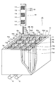
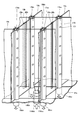
- a cooling device 10 has a cooling tank 12, and an open space 10a is formed by a bottom wall 12a and a side wall 12b of the cooling tank 12.
- an open space 10a is formed by a bottom wall 12a and a side wall 12b of the cooling tank 12.
- storage unit 15aa 16 storage units 15aa, 15ab, 15ac, 15ad, 15ba, 15bb, 15bc, 15bd, 15ca, 15cb, 15cc, 15cd, 15da, 15db, 15dc, 15dd (hereinafter collectively referred to as “storage unit 15aa”) May be described as “ ⁇ 15dd”). And at least 1 electronic device 100 is accommodated in each accommodating part. In the open space 10 a of the cooling tank 12, the cooling liquid 11 is put up to the liquid level 19.
- the bottoms of the storage portions 15aa, 15ab, 15ac, 15ad, 15ba, 15bb, 15bc, 15bd, 15ca, 15cb, 15cc, 15cd, 15da, 15db, 15dc, 15dd have inflow openings 16aa, 16ab, 16ac, 16 ad, 16 ba, 16 bb, 16 bc, 16 bd, 16 ca, 16 cb, 16 cc, 16 cd, 16 da, 16 db, 16 dc, 16 dd (hereinafter may be collectively referred to as “inflow openings 16aa to 16dd”) are formed. .
- the outflow openings 17aa, 17ab, 17ac, 17ad, 17ae, 17ba, 17bb, 17bc, 17bd, 17be, 17ca, 17cb, 17cc, 17cd , 17ce, 17da, 17db, 17dc, 17dd, 17de, 17ea, 17eb, 17ec, 17ed, and 17ee (hereinafter sometimes collectively referred to as “outflow openings 17aa to 17ee”).
- the outflow opening is formed at a position where a plurality of internal partition walls forming each storage portion intersect with each other or in the vicinity thereof.
- the storage portion 15aa is formed by vertical internal partition walls 13a and 13b and horizontal internal partition walls 14a and 14b, and the internal partition wall 13a and the internal partition wall 14a intersect each other.
- Outflow openings 17aa, 17ba, 17ab, so as to be located at a point where the partition wall 13a and the inner partition wall 14b intersect, a point where the inner partition wall 13b and the inner partition wall 14a intersect, and a point where the inner partition wall 13b and the inner partition wall 14b intersect, respectively. 17bb is formed.
- FIG. 1 the storage portion 15aa is formed by vertical internal partition walls 13a and 13b and horizontal internal partition walls 14a and 14b, and the internal partition wall 13a and the internal partition wall 14a intersect each other.
- Outflow openings 17aa, 17ba, 17ab so as to be located at a point where the partition wall
- the storage portion 15bb is formed by the vertical internal partition walls 13b and 13c and the horizontal internal partition walls 14b and 14c, and the internal partition wall 13b and the internal partition wall 14b intersect each other.
- the outflow openings 17bb, 17cb are respectively positioned at the point where the internal partition wall 13b and the internal partition wall 14c intersect, the point where the internal partition wall 13c and the internal partition wall 14b intersect, and the point where the internal partition wall 13c and the internal partition wall 14c intersect. 17bc and 17cc are formed.
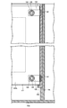
- the outflow opening is formed at one end of the outflow pipe 170 that extends through the bottom wall 12a of the cooling bath 12 to the vicinity of the liquid surface 19.
- the outflow openings 17bb, 17cb, 17bc, 17cc are formed by vertical internal partition walls 13b, 13c and horizontal internal partition walls 14b, 14c. 13b and the inner partition wall 14b intersect, the inner partition wall 13b and the inner partition wall 14c intersect, the inner partition wall 13c and the inner partition wall 14b intersect, and the inner partition wall 13c and the inner partition wall 14c intersect, respectively. It is formed at one end of the outflow pipe 170.
- the other end of the outflow pipe has a bottom opening 18aa, 18ab, 18ac, 18ad, 18ae, 18ba, 18bb, 18bc, 18bd, 18be, 18ca, 18cb, 18cc, 18cd, 18ce, 18da, 18db, 18dc, 18dd, 18de, 18ea, 18eb, 18ec, 18ed, and 18ee (hereinafter, collectively referred to as “bottom openings 18aa to 18ee”) are formed.
- outflow openings 17bb, 17bc, 17cb, and 17cc are formed by the outflow pipes 170 arranged at the four corners.
- the outflow opening 17bb is a part of the outflow opening for the storage part 15aa and at the same time a part of the outflow opening for the storage parts 15ab, 15ba, and 15bb.
- outflow openings 17bc, 17cb, and 17cc are arbitrary, and one or a plurality of outflow pipes may be provided in the vicinity of a position where a plurality of internal partition walls forming each storage part intersect each other.
- the outflow pipe does not need to be integrated with the internal partition, and may be a pipe disposed away from the internal partition.
- one or more small holes 171 may be formed in the outflow pipe 170 in the longitudinal direction of the outflow pipe 170. As will be described later, these small holes 171 promote the circulation of the coolant 11 in the middle of the storage portion in the depth direction.
- the inflow openings 16aa to 16dd do not need to be cylindrical openings as shown in the figure.
- a header having a plurality of nozzles is connected to one end of the cylinder to form inflow openings by a number of nozzles. May be.
- the electronic device 100 is stored and immersed in the coolant 11.
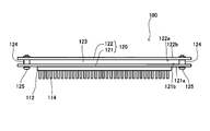
- the electronic device 100 has a multi-stage board 120 structure.
- the electronic device 100 includes a processor board 121 (“first board”) in which one processor (CPU) 110 and two processors (GPU) 112 are mounted on the front surface 121a (“first surface”). ) And a board 122 (“second board”) having a surface 122 a (“third surface”) facing the back surface 121 b (“second surface”) of the processor board 121. And a flow channel 123 formed by a gap between the back surface 121b of the processor board 121 and the surface 122a of the board 122. As shown in FIGS.
- the electronic device 100 further includes a plurality of spacers 124 that hold the gap and a plurality of screws 125.
- Each of the plurality of screws 125 penetrates and fixes each of the processor board 121, the board 122, and the plurality of spacers 124.
- Each of the processor (CPU) 110 and the processor (GPU) 112 includes a heat radiating member (heat radiating fin) 114 thermally connected thereto.
- peripheral electronic components are naturally mounted on the surface 121a of the processor board 121, and peripheral electronic components are similarly mounted on the one surface 122b of the board 122. However, these electronic components are not shown. Peripheral electronic components may also be mounted on the other surface 122a of the board 122. However, it is preferable that the electronic component is mounted so as not to be an obstacle as much as possible with respect to the flow of the coolant through the flow channel 123.
- each of the storage portions 15aa to 15dd is provided with a pair of board retainers 20a or 20b.
- the pair of board retainers 20a or 20b is configured to hold one or both of the processor board 121 and the board 122 included in the electronic device 100. Further, as shown in FIGS. 5, 6, 7 and 8, each element of the board retainer seems to have closed the lower end of the groove in the guide rail in which the both ends of the processor board 121 are formed. It has a simple structure. In the example in which the electronic device 100 is housed in the housing portion 15bb shown in FIGS. 5 to 8, the pair of board retainers 20b hold both side ends of the processor board 121.
- the board retainer 20a or 20b can be provided at an arbitrary position on the plurality of internal partition walls forming each storage portion, but may be installed as an independent element separated from the internal partition wall.
- a part of the element of the board retainer is fixed by being embedded in the internal partition, but this is an example, and the method of fixing the board retainer is not limited to this. .
- the present inventor is a compound in which a fully fluorinated product has high electrical insulation and high heat transfer ability, is inert, has high thermal and chemical stability, is nonflammable, and does not contain oxygen. Therefore, paying attention to the excellent characteristics such as zero ozone depletion coefficient, a coolant containing such a fully fluorinated product as a main component is used as a coolant for immersion cooling of high-density electronic equipment.
- the invention of the cooling system to be used has been completed and a patent application has been filed (Japanese Patent Application No. 2014-170616).
- the cooling tank 12 has an inlet 16 for distributing the coolant 11 through distribution pipes (not shown) toward the inflow openings 16aa to 16dd provided in the storage portions 15aa to 15dd, and the storage portions.
- An outlet 18 is provided for collecting the coolant 11 that has passed through the outlet openings 17aa to 17ee of 15aa to 15dd through a collecting pipe (not shown).
- the cooling liquid 11 cooled to a desired temperature is continuously supplied to each of the electronic devices 100 stored in the storage portions 15aa to 15dd so as to be maintained at a predetermined temperature or lower during operation.
- the heated cooling liquid 11 that has come out from the outlet 18 of the cooling tank 12 is cooled by a heat exchanger, and the cooled cooling liquid is supplied to the inlet 16 of the cooling tank 12.
- the return flow passage 30 may be configured. As shown in the figure, the outlet 18 and the inlet 16 of the cooling tank 12 are connected by a flow passage 30, and a pump 40 that moves the cooling liquid 11 and a heat exchanger 90 that cools the cooling liquid 11 are provided in the flow passage 30. It has been.
- a flow rate adjusting valve 50 and a flow meter 70 for adjusting the flow rate of the coolant 11 flowing through the flow passage 30 are also provided in the flow passage 30.
- the pump 40 preferably has a performance of moving a liquid having a relatively large kinematic viscosity (a kinematic viscosity at room temperature of 25 ° C. exceeds 3 cSt).
- a kinematic viscosity at room temperature of 25 ° C. exceeds 3 cSt For example, when Fluorinert FC-43 or FC-40 is used as the coolant 11, the kinematic viscosity of FC-43 is about 2.5 to 2.8 cSt, and the kinematic viscosity of FC-40 is 1.8 to 2 This is because it is about 2 cSt.
- the flow rate adjustment valve 50 may be manually operated, or may be provided with an adjustment mechanism that keeps the flow rate constant based on the measurement value of the flow meter 70.
- the heat exchanger 90 may be various circulating heat exchangers (radiators or chillers) or coolers.
- the coolant 11 that has entered from the inlet 16 is distributed toward inflow openings 16aa to 16dd formed at the bottoms of the storage portions 15aa to 15dd via a distribution pipe (not shown).
- the coolant 11 blows upward from the inflow openings 16aa to 16dd, and directly cools the three processors 112, 110, 112 and peripheral electronic components (not shown) on the surface 121a of the processor board 121 of the electronic device 100. .
- the heat dissipation member 114 thermally connected to the three processors 112, 110, and 112 and peripheral electronic components ( While moving away from the surface (not shown), it rises toward the liquid level 19 and further moves toward the outflow openings 17bb, 17bc, 17cb, 17cc.
- the volume of the storage portions 15aa to 15dd is as small as about 1/16 of the volume of the open space 10a of the cooling bath 12, and the electronic device 100 stored therein is also about 1 / of the width of the cooling bath 12. Therefore, the cooling efficiency of the electronic device 100 by the coolant 11 is extremely good, and the coolant 11 can be effectively prevented from staying around the electronic device 100.
- the electronic device 100 has a multi-stage board 120 structure, the number of layers of multilayer wiring per board can be reduced as compared with the conventional one, and the thickness of the processor board 121 can be reduced. Therefore, heat from the processors 112, 110, and 112 mounted on the processor board 121 is easily transferred to the back surface 121 b of the processor board 121.
- the processor board 121 When a part of the cooled coolant 11 flowing through each of the storage portions 15aa to 15dd passes through the flow channel 123 formed by the gap between the back surface 121b of the processor board 121 and the surface 122a of the board 122, the processor board 121 The heat is quickly and efficiently taken away from the rear surface 121b of the paper. In this way, the cooling liquid 11 can quickly and efficiently remove heat from both sides of the processor board 121 that generates a large amount of heat, thereby improving the efficiency of cooling the electronic device.
- the coolant 11 that has been deprived of heat from the electronic device 100 passes through the outflow openings 17aa to 17ee located in the vicinity of the liquid surface 19 on the cooling tank 12, descends in the outflow pipe 170, and bottom openings 18aa to 18ee. And is collected at the outlet 18 via a collecting pipe (not shown).
- a collecting pipe (not shown).
- the coolant 11 flows out into the outflow pipe 170 through the small holes 171. Accordingly, the circulation of the cooling liquid 11 in the middle of the depth direction of the storage portion is promoted, and the cooling liquid 11 is distributed through the entire multistage board 120 of the electronic device 100, so that peripheral electronic components (not shown) are more efficiently performed. Can be cooled.
- each of the outflow pipes 170 has six small holes 171 formed at regular intervals. However, this is merely an example, and those skilled in the art can arbitrarily determine the number and position of the small holes. Good.
- the temperature of each storage unit is constantly monitored in a control device (not shown), and an input signal according to a temperature change in the storage unit transmitted from the control device is received.
- Another flow rate adjusting valve (not shown) for adjusting the flow rate of the coolant 11 passing through the inflow openings 16aa to 16dd of the storage portions 15aa to 15dd is provided for each distribution pipe (from the inlet 16 to the inflow openings 16aa to 16dd). (Not shown).
- the cooling strength of the electronic device by the cooling liquid can be individually managed by individually adjusting the flow rate of the cooling liquid flowing through each storage unit, so that the cooling performance of a plurality of electronic devices Can be managed in detail.
- a first temperature sensor for liquid is provided in each of the storage portions 15aa to 15dd, and a temperature higher than a preset temperature is detected by the first temperature sensor.
- a mechanism for stopping the operation of the electronic device 100 housed in the housing portion where the temperature is detected or cutting off the power supply to the electronic device 100 when the temperature is detected. Good.
- an abnormal temperature rise exceeding the set temperature does not occur in the coolant 11 flowing through each storage section, and damage to electronic equipment and harmful compounds from fluorocarbons are prevented. Occurrence can be prevented.
- a second temperature sensor (not shown) is provided in the periphery of 100, and when the second temperature sensor detects a temperature higher than a preset temperature, the operation of the electronic device 100 is stopped, or the electronic device A mechanism (not shown) for cutting off power supply to 100 may be further provided.
- the electronic device 100 is a multistage board 120 having a two-stage structure including one processor board 121 and one board 122, but a multistage board having three or more stages may be configured.
- a three-stage structure using two processor boards and one board is used.
- the back surface of one processor board and one surface of one board are opposed to each other, and the first surface is defined by these two surfaces.
- the flow channel may be formed, and the other surface of the one board may be opposed to the back surface of the other processor board, and the second flow channel may be formed by these two surfaces.
- the cooling liquid can quickly and efficiently take away heat from both sides of the processor board having a large calorific value, and the efficiency of cooling the electronic device is improved. Similar effects can be achieved.
- each of the plurality of electronic devices cooled in the cooling device is connected to an external power source and an external control device via a power line and a signal line (not shown) extending from the opening side of the cooling tank.
- a power line and a signal line (not shown) extending from the opening side of the cooling tank.
- the number of power lines and signal lines connected to the electronic device has become enormous due to the multi-stage board of the electronic device and the increase in the number of units, which hinders the movement of the refrigerant essential for effective cooling of the electronic device.
- the flowability of the refrigerant decreases and cooling efficiency decreases, and the handling of electronic equipment installation and maintenance becomes troublesome. There is.
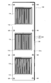
- 11 and 12 show a coupling relationship between the electronic device 100 and the cooling device 10 according to another embodiment.
- the power line 140 and the signal line 150 are installed in the gap between the both side ends of the processor board 121 included in the electronic device 100 and the board retainer 20b provided in the internal partition wall 13c of the cooling device 10,
- the power supply line 140 is connected to the connector 130 provided on the surface 121a of the processor board 121, and the signal line 150 can be connected to the connector 131 provided on the surface 121a.
- the power supply line 140 and the signal line 150 may have a bus structure so as to be branched from an arbitrary place in the vertical direction.
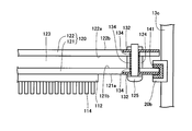
- 13 and 14 show a coupling relationship between the electronic device 100 and the cooling device 10 according to still another embodiment.
- the power supply line 141 is embedded in the groove of the board retainer 20b provided in the internal partition wall 13c of the cooling device 10.
- a strip-shaped electrical contact 132 is provided on the back surface 121b of the processor board 121 among both side ends of the processor board 121 included in the electronic device 100.
- the strip-shaped electrical contact 132 is penetrated by a screw 125. Around the hole, it has a width approximately equal to the maximum diameter of the head and nut of the screw 125 and the diameter of the spacer 124.
- An electric contact 132 having a similar shape is also provided on the surface 122b of the board 122.
- the power supply line 141 is electrically connected to the electrical contact 132 of the processor board 121.
- the signal line 150 may be used instead of the power supply line 141 so that the electrical signal is transmitted through the above-described path.
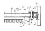
- FIG. 15 shows a coupling relationship between the electronic device 100 and the cooling device 10 according to still another embodiment.
- a strip-shaped electrical contact 132 is provided on the surface 122 a of the board 122.
- the electrical contact 132 on the back surface 121 b of the processor board 121 and the electrical contact 132 on the surface 122 a of the board 122 are electrically connected via a conductive spacer 124.
- the screw 125 may not be conductive.
- Other components are the same as those of the embodiment shown in FIGS.
- the power from the power line 141 is not only supplied to the processor 112 and peripheral electronic components via the electrical contacts 132 on the processor board 121, but also the electrical contacts 132 on the processor board 121. , Spacers 124, and electrical contacts 132 on the board 122 are also supplied to the electronic components on the board 122.
- the signal line 150 may be used instead of the power supply line 141 so that the electrical signal is transmitted through the above-described path.
- FIG. 16 shows a coupling relationship between the electronic device 100 and the cooling device 10 according to still another embodiment.
- a strip-shaped electrical contact 132 is provided on the surface 121 a of the processor board 121.
- the spacer 124 is formed with a conductive hole 134 through which the screw 125 passes.
- the processor board 121 and the board 122 are similarly formed with conductive holes 134 through which the screws 125 pass.
- the electrical contact 132 on the surface 121 a of the processor board 121 is electrically connected to the electrical contact 132 on the surface 122 b of the board 122 via the conductive screw 125 and the conductive hole 134.
- Other components are the same as those of the embodiment shown in FIGS.
- FIG. 17 shows a coupling relationship between the electronic device 100 and the cooling device 10 according to still another embodiment.
- the configuration of this embodiment is the same as that of the embodiment shown in FIG. 15 except that a conductive screw is used as the screw 125.
- FIG. 18 shows a coupling relationship between the electronic device 100 and the cooling device 10 according to still another embodiment.
- the configuration of this embodiment is the same as the configuration of the embodiment shown in FIG. 16 except that a screw having no conductivity is used as the screw 125.
- FIG. 19 shows a coupling relationship between the electronic device 100 and the cooling device 10 according to still another embodiment.
- the configuration of this embodiment is the same as that of the embodiment shown in FIG. 18 except that a conductive spacer is used as the spacer 124.
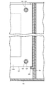
- FIG. 20 shows a coupling relationship between the electronic device 100 and the cooling device 10 according to still another embodiment.
- a strip-shaped electrical contact 132b is provided on the front surface 121a of the processor board 121, and another strip-shaped electrical contact 132a is provided on the back surface 121b.
- an electrical contact 132b is provided on the surface 122a of the board 122, and an electrical contact 132a is provided on the surface 122b.
- the spacer 124 has an inner insulating portion through which the conductive screw 125 passes and an outer conductive collar 133.
- the electrical contact 132b on the surface 121a of the processor board 121 is electrically connected to the conductive collar 133 of the spacer 124 via a conductor passing through the processor board 121, and the electrical contact 132b on the surface 122a of the board 122 is The spacer 124 is electrically connected to the conductive collar 133.
- the electrical contact 132a on the back surface 121b of the processor board 121 is electrically connected to the conductive screw 125 via a conductor in the processor board 121, and the electrical contact 132a on the surface 122b of the board 122 is The conductive screw 125 is electrically connected.
- the positive power supply line 141a and the negative power supply line 141b are embedded in the insulating board retainer 20b provided in the internal partition wall 13c while maintaining electrical insulation between each other.
- the electrical contact 132a of the processor board 121 is electrically connected to the positive power supply line 141a at the same time.
- the electrical contact 132a of 122 is electrically connected to the positive power supply line 141a through the conductive screw 125 and the electrical contact 132a of the processor board 121.
- the electrical contact 132b of the processor board 121 is electrically connected to the negative power supply line 141b, and at the same time, the electrical contact 132b of the board 122 is electrically connected to the conductive collar 133 and the processor board 121 outside the spacer 124. It is electrically connected to the negative power line 141b through the contact 132b.
- the power from the positive power supply line 141a and the negative power supply line 141b is not only supplied to the processor 112 and peripheral electronic components via the electrical contacts 132a and 132b on the processor board 121, but also the processor board. It is also supplied to the electronic components on the board 122 through the electrical contacts 132 a and 132 b on the 121, the conductive screw 125, the conductive collar 133 and the electrical contacts 132 a and 132 b on the board 122.
- FIG. 21 shows a coupling relationship between the electronic device 100 and the cooling device 10 according to still another embodiment.
- the conductive board retainers 20c and 20d are embedded in the insulating internal partition wall 13c, and when the electronic device 100 and the cooling device 10 are operated, A positive voltage and a negative voltage are respectively applied to the conductive board retainer 20d. Accordingly, during operation, the conductive board retainer 20c functions as a positive power supply line, and the conductive board retainer 20d functions as a negative power supply line.
- a strip-shaped electrical contact 132b is provided near the side end, and an electrical contact 132a is provided near the inside.
- an electrical contact 132a is provided on the surface 122a of the board 122, and an electrical contact 132b is provided on the surface 122b.
- the spacer 124 has an inner insulating portion through which the conductive screw 125 passes and an outer conductive collar 133.
- the electrical contact 132b on the back surface 121b of the processor board 121 is electrically connected to the conductive screw 125 via a conductor portion in the processor board 121, and the electrical contact 132a is electrically connected to the conductive collar 133 of the spacer 124. It is connected.
- the electrical contact 132a on the surface 122a of the board 122 is electrically connected to the conductive collar 133 of the spacer 124, and the electrical contact 132b on the surface 122b of the board 122 is electrically connected to the conductive screw 125.
- the electrical contact 132a of the board 122 is connected to the positive power source.
- the electrical contacts 132a of the processor board 121 are electrically connected to the board retainer 20c via the conductive collar 133 outside the spacer 124 at the same time as being electrically connected to the board retainer 20c functioning as a line. .
- the electrical contact 132b of the processor board 121 is electrically connected to the board retainer 20d functioning as a negative power supply line, and at the same time, the electrical contact 132b of the board 122 is connected to the conductive screw 125 and the processor board 121. It is electrically connected to the board retainer 20d through the electrical contact 132b.
- power from the board retainers 20c and 20d is supplied to the processor and peripheral electronic components on the processor board 121 and the board 122 via the electrical contacts 132a and 132b, the conductive screws 125, and the conductive collar 133. Supplied to electronic components.
- the power supply line or the signal line is not necessarily provided by a member different from the board retainer, and the board retainer may function as a power supply line or a signal line as in the present embodiment.
- the number of power lines and signal lines becomes enormous due to the increase in the number of units and the increase in the number of units.
- the flowability of the refrigerant decreases, resulting in a decrease in cooling efficiency, and handling in the installation and maintenance of electronic devices. The problem of troublesomeness can be reduced.
- FIG. 1 and FIG. 7 to FIG. 9 the example in which the inflow opening is formed at the bottom of each storage unit has been described. Good.
- a cooling device according to another embodiment of the present invention will be described with reference to FIGS. 22 and 23, and a cooling device according to another embodiment will be described with reference to FIG.
- the 22 and 23 are a plan view and a longitudinal sectional view showing the configuration of a main part of a cooling device according to another embodiment, and an inflow opening for the cooling liquid 11 at the bottom of each of the storage portions 15aa to 15dd of the cooling device 10.
- Inflow openings are formed by the inflow pipes 160 provided on the side surfaces of the storage portions 15aa to 15dd. That is, the cooling device 10 further includes an inflow pipe 160 that passes through the bottom wall 12a and extends to the vicinity of the liquid surface 19, and the inflow pipe 160 includes a plurality of nozzles 161 in the longitudinal direction of the inflow pipe 160.
- the inflow pipe 160 and the outflow pipe 170 may be alternately arranged at or near the position where the plurality of internal partition walls forming the storage portions 15aa to 15dd intersect each other.
- the storage portion 15bb is formed by the vertical internal partition walls 13b and 13c and the horizontal internal partition walls 14b and 14c, and the internal partition wall 13b and the internal partition wall 14c intersect each other.
- the outflow pipe 170 is disposed at the point where the internal partition wall 13c and the internal partition wall 14b intersect, and the outflow openings 17cb and 17bc are formed at the upper end of the outflow pipe 170, respectively, as in FIG. is there.
- an inflow pipe 160 is arranged at a point where the internal partition wall 13b and the internal partition wall 14b intersect, and at a point where the internal partition wall 13c and the internal partition wall 14c intersect, and the inflow pipe 160 includes a plurality of nozzles 161 in its longitudinal direction.
- the inflow opening 116bb is formed in each of the plurality of nozzles. Note that the inflow pipe and the outflow pipe do not need to be integrated with the internal partition wall, and may be pipes arranged away from the internal partition wall.
- the inflow pipe 160 has a structure in which the inside is divided into four sections, and the coolant 11 flowing through one of the sections is an inflow formed in each of the plurality of nozzles 161. It blows out into the storage portion 15bb through the opening 116bb. Therefore, in this embodiment, a pair of inflow openings are formed in the diagonal direction on the side surface of each storage portion. Further, since the inflow pipe 160 has a structure in which the inside is divided into four sections, the flow rate of the coolant flowing through each section can be individually controlled.
- each storage unit is constantly monitored by a control device (not shown), and an inflow opening of the plurality of nozzles 161 is received in response to an input signal transmitted from the control device according to a temperature change in the storage unit.
- Another flow rate adjustment valve (not shown) for adjusting the flow rate of the cooling liquid 11 passing through the pipe may be provided at an appropriate position on the path from the bottom opening to the inflow opening described later for each section. Thereby, it is possible to individually control the flow rate of the coolant from the pair of inflow openings in the diagonal direction for each storage unit.
- the outflow opening 17bc and 17cb may be formed at the upper end of the outflow pipe 170 without forming a small hole in the outflow pipe 170.
- these outflow openings can be a common outflow opening for a plurality of storage units, similar to the outflow openings in the embodiment shown in FIGS.
- three processors 112 mounted on the surface 121a of the processor board 121 are formed from a plurality of inflow openings 116bb formed in a pair in the diagonal direction on the side surface of the storage portion 15bb. , 110, 112, the electronic device 100 is forcibly cooled by the plurality of flows of the coolant 11, so that the cooling efficiency is further improved.
- the position and number of the inflow pipe and the outflow pipe are arbitrary, and the inflow pipe and the outflow pipe are respectively provided in the vicinity of the position where the plurality of internal partition walls forming each storage part intersect each other. Of course, one or more may be provided.
- a part of the cooled coolant 11 flowing through the storage portion 15bb may pass through the flow channel 123 formed by the gap between the back surface 121b of the processor board 121 and the surface 122a of the board 122. is important.
- the outflow pipe 170 constitutes a double pipe 180 containing the outflow pipe 170 in the inflow pipe 160, in other words, a double pipe having the outflow pipe 170 as an inner pipe and the inflow pipe 160 as an outer pipe. It is characterized in that 180 is configured.
- the inflow pipe 160 has a plurality of nozzles 161 in the longitudinal direction of the inflow pipe 160, and the inflow openings 116aa to 116ee are formed in each of the plurality of nozzles 161, and the upper end of the inflow pipe 160 is completely closed.
- the inflow pipe 160 has a structure in which the inside is divided into four sections, and the cooling liquid 11 flowing through one of the sections is an inflow opening 116aa formed in each of the plurality of nozzles 161. It is the same as in the embodiment shown in FIG. 22 and FIG. 23 that it is blown into the storage portions 15aa to 15dd through .about.116ee.
- the double pipe 180 may be disposed at a position where a plurality of internal partition walls forming the storage portions 15aa to 15dd intersect each other or in the vicinity thereof. That is, the point where the internal partition 13b and the internal partition 14b intersect, the point where the internal partition 13b and the internal partition 14c intersect, the point where the internal partition 13c and the internal partition 14b intersect, and the point where the internal partition 13c and the internal partition 14c intersect
- the double pipes 180 may be arranged so as to be located respectively. Note that the double pipe need not be integrated with the internal partition, and may be a pipe disposed away from the internal partition.
- inflow openings are formed at the four corners of the side surface of each storage unit.
- the inflow pipe 160 has a structure in which the inside is divided into four sections, the flow rate of the coolant flowing through each section can be individually controlled. That is, the temperature of each storage unit is constantly monitored by a control device (not shown), and an inflow opening of the plurality of nozzles 161 is received in response to an input signal transmitted from the control device according to a temperature change in the storage unit.
- Another flow rate adjustment valve (not shown) for adjusting the flow rate of the cooling liquid 11 passing through may be provided at an appropriate position on the path from the bottom opening to the inflow opening for each section.
- bottom openings 118aa to 118ee are formed at the lower end of the inflow pipe 160 corresponding to the outer pipe of the double pipe 180.
- the bottom openings 118aa to 118ee correspond to four compartments inside the inflow pipe 160, respectively.
- the upper end of the inflow pipe 160 corresponding to the outer pipe of the double pipe 180 is completely closed.
- bottom openings 18aa to 18ee are formed.
- outflow opening formed at the upper end of the outflow pipe 170 corresponding to the inner pipe of the double pipe 180 can be a common outflow opening for a plurality of storage portions is the same as the outflow opening in the embodiment shown in FIGS. It is the same.
- a plurality of inflow openings 116bb formed in the four corners of the side surface of the storage portion 15bb in the depth direction are directed to the three processors 112, 110, 112 mounted on the surface 121a of the processor board 121. Since the electronic device 100 is forcibly cooled by the plurality of flows of the coolant 11, the cooling efficiency is further improved.
- the position and number of the double pipes are arbitrary, and one or a plurality of double pipes are provided in the vicinity of a position where a plurality of internal partition walls forming each storage part intersect each other. Of course, it may be provided.
- a part of the cooled coolant 11 flowing through the storage portion 15bb may pass through the flow channel 123 formed by the gap between the back surface 121b of the processor board 121 and the surface 122a of the board 122. is important.
- the inflow pipe is arranged at a position where a plurality of internal partition walls forming each storage portion intersect with each other or in the vicinity thereof, but the form of forming the inflow opening on the side surface of each storage portion is It is not limited to these.
- a hollow internal partition is employed, and one or more slits are formed in the wall of the internal partition to form an inflow opening, and the cooled coolant is contained inside
- the coolant may flow through the partition wall and blow out the cooling liquid into the housing through one or more slits.
- a branch pipe through which the cooled coolant passes is provided on a part or the entire surface of the inner partition wall, and an inflow opening is formed at an arbitrary position and number of branch pipes. The coolant may be blown out into the storage unit.
- the electronic device 100 may be an electronic device such as a server including a blade server, a network device such as a router or a network switch, or a storage device such as an SSD or a sealed HDD (Hard Disk Drive).
- a width for example, about 1/2, 1/3, 1/4
- a conventional general width may be used.
- an electron having a width smaller than that of the conventional case is accommodated in a storage portion having a volume of about 1/4 or less than about 1/4 of the volume of the open space of the cooling tank.
- the present invention can be widely applied to the cooling of electronic devices that require ultra-high performance operation and stable operation and generate a large amount of heat from itself.
- Cooling device 10a Open space 100 Electronic device 110 Processor (CPU) 112 processor (GPU) 114 Heat dissipation member 120 Multistage board 121 Processor board (first board) 121a surface (first surface) 121b Rear surface (second surface) 122 board (second board) 122a surface (third surface) 122b surface 123 flow channel 124 spacer 125 screw 130, 131 connector 132, 132a, 132b electrical contact 133 conductive collar 134 conductive hole 140, 141, 141a, 141b power supply line 150 signal line 11 coolant 12 cooling tank 12a bottom wall 12b Side wall 13a, 13b, 13c, 13d, 13e Internal partition 14a, 14b, 14c, 14d, 14e Internal partition 15aa, 15ab, 15ac, 15ad, 15ba, 15bb, 15bc, 15bd, 15ca, 15cb, 15cc, 15cd, 15da, 15db 15 dc,
Landscapes
- Engineering & Computer Science (AREA)
- Microelectronics & Electronic Packaging (AREA)
- Physics & Mathematics (AREA)
- Thermal Sciences (AREA)
- Theoretical Computer Science (AREA)
- General Physics & Mathematics (AREA)
- Computer Hardware Design (AREA)
- General Engineering & Computer Science (AREA)
- Power Engineering (AREA)
- Human Computer Interaction (AREA)
- Condensed Matter Physics & Semiconductors (AREA)
- Aviation & Aerospace Engineering (AREA)
- Cooling Or The Like Of Electrical Apparatus (AREA)
- Mounting Of Printed Circuit Boards And The Like (AREA)
- Cooling Or The Like Of Semiconductors Or Solid State Devices (AREA)
Abstract
Description
10a 開放空間
100 電子機器
110 プロセッサ(CPU)
112 プロセッサ(GPU)
114 放熱部材
120 多段ボード
121 プロセッサボード(第1のボード)
121a 表面(第1の面)
121b 背面(第2の面)
122 ボード(第2のボード)
122a 面(第3の面)
122b 面
123 フローチャネル
124 スペーサ
125 ねじ
130、131 コネクタ
132、132a、132b 電気接点
133 導電性カラー
134 導電性ホール
140、141、141a、141b 電源ライン
150 信号ライン
11 冷却液
12 冷却槽
12a 底壁
12b 側壁
13a、13b、13c、13d、13e 内部隔壁
14a、14b、14c、14d、14e 内部隔壁
15aa、15ab、15ac、15ad、15ba、15bb、15bc、15bd、15ca、15cb、15cc、15cd、15da、15db、15dc、15dd 収納部
16 入口
16aa、16ab、16ac、16ad、16ba、16bb、16bc、16bd、16ca、16cb、16cc、16cd、16da、16db、16dc、16dd 流入開口
116aa、116ab、116ac、116ad、116ae、116ba、116bb、116bc、116bd、116be、116ca、116cb、116cc、116cd、116ce、116da、116db、116dc、116dd、116de、116ea、116eb、116ec、116ed、116ee 流入開口
160 流入管
161 ノズル
17aa、17ab、17ac、17ad、17ae、17ba、17bb、17bc、17bd、17be、17ca、17cb、17cc、17cd、17ce、17da、17db、17dc、17dd、17de、17ea、17eb、17ec、17ed、17ee 流出開口
170 流出管
171 小孔
18 出口
180 二重管
18aa、18ab、18ac、18ad、18ae、18ba、18bb、18bc、18bd、18be、18ca、18cb、18cc、18cd、18ce、18da、18db、18dc、18dd、18de、18ea、18eb、18ec、18ed、18ee 底部開口
118aa、118ab、118ac、118ad、118ae、118ba、118bb、118bc、118bd、118be、118ca、118cb、118cc、118cd、118ce、118da、118db、118dc、118dd、118de、118ea、118eb、118ec、118ed、118ee 底部開口
19 液面
20a、20b、20c、20d ボードリテーナ
30 流通路
40 ポンプ
50 流量調整バルブ
70 流量計
90 熱交換器
Claims (22)
- 冷却装置内の冷却液中に浸漬されて直接冷却される電子機器であって、
前記電子機器は、冷却装置の複数の収納部の各々に収納されるよう構成され、前記冷却装置は、底壁及び側壁によって形成される開放空間を有する冷却槽と、前記冷却槽内に複数の内部隔壁を設けることにより前記開放空間を分割して形成される、配列された前記複数の収納部と、前記複数の収納部の各々に形成される、冷却液の流入開口及び流出開口とを有し、前記流入開口が、各収納部の底部又は側面に形成され、前記流出開口が、各収納部を流通する前記冷却液の液面近傍に形成されており、
前記電子機器は、
1つ以上のプロセッサがその上に搭載される第1の面と、前記第1の面と反対側の第2の面とを有する、第1のボードと、
前記第1のボードの前記第2の面に対向する第3の面を有する第2のボードと、
前記第1のボードの前記第2の面と前記第2のボードの前記第3の面との隙間により形成されるフローチャネルと、
を有する、電子機器。 - 前記隙間を保持する複数のスペーサと、複数のねじをさらに有し、
前記複数のねじの各々は、前記第1のボード、前記第2のボード、及び前記複数のスペーサの各々を貫通し、固定する、請求項1に記載の電子機器。 - 前記第1のボード又は第2のボードは、1つ以上のコネクタを有し、
前記コネクタは、前記各収納部内で前記第1のボード及び前記第2のボードのいずれか一方又は両方を保持する一対のボードリテーナに設けられた電源ライン又は信号ラインと電気的に接続される、請求項2に記載の電子機器。 - 前記第1のボード及び前記第2のボードは、それぞれ電気接点を有し、
前記第1のボードの電気接点と前記第2のボードの電気接点を、導電性のねじを介して電気的に接続し、
前記第1のボードの電気接点及び前記第2のボードの電気接点の一方又は両方は、前記各収納部内で前記第1のボード及び前記第2のボードのいずれか一方又は両方を保持する一対のボードリテーナに設けられた電源ライン又は信号ラインと電気的に接続される、請求項2に記載の電子機器。 - 前記スペーサには、前記導電性のねじが貫通する導電性ホールが形成されている、請求項4に記載の電子機器。
- 前記第1のボード及び前記第2のボードは、それぞれ電気接点を有し、
前記第1のボードの電気接点と前記第2のボードの電気接点を、導電性のねじ及び導電性のスペーサを介して電気的に接続し、
前記第1のボードの電気接点及び前記第2のボードの電気接点の一方又は両方は、前記各収納部内で前記第1のボード及び前記第2のボードのいずれか一方又は両方を保持する一対のボードリテーナに設けられた電源ライン又は信号ラインと電気的に接続される、請求項2に記載の電子機器。 - 前記第1のボード及び前記第2のボードは、それぞれ電気接点を有し、
前記第1のボードの電気接点と前記第2のボードの電気接点を、前記スペーサに形成された、前記ねじが貫通する導電性ホールを介して電気的に接続し、
前記第1のボードの電気接点及び前記第2のボードの電気接点の一方又は両方は、前記各収納部内で前記第1のボード及び前記第2のボードのいずれか一方又は両方を保持する一対のボードリテーナに設けられた電源ライン又は信号ラインと電気的に接続される、請求項2に記載の電子機器。 - 前記第1のボード及び前記第2のボードは、それぞれ電気接点を有し、
前記第1のボードの電気接点と前記第2のボードの電気接点を、導電性のスペーサを介して電気的に接続し、
前記第1のボードの電気接点及び前記第2のボードの電気接点の一方又は両方は、前記各収納部内で前記第1のボード及び前記第2のボードのいずれか一方又は両方を保持する一対のボードリテーナに設けられた電源ライン又は信号ラインと電気的に接続される、請求項2に記載の電子機器。 - 複数の電子機器を冷却液中に浸漬して直接冷却する冷却装置であって、
底壁及び側壁によって形成される開放空間を有する冷却槽と、
前記冷却槽内に複数の内部隔壁を設けることにより前記開放空間を分割して形成される、配列された複数の収納部と、
前記複数の収納部の各々に形成される、冷却液の流入開口及び流出開口と、
前記各収納部に設けられた一対のボードリテーナと、
を有し、
前記流入開口は、各収納部の底部又は側面に形成され、前記流出開口は、各収納部を流通する前記冷却液の液面近傍に形成されており、
前記一対のボードリテーナは、電子機器が有する第1のボード及び第2のボードのいずれか一方又は両方を保持するよう構成され、前記電子機器は、1つ以上のプロセッサがその上に搭載される第1の面と、前記第1の面と反対側の第2の面とを有する、第1のボードと、前記第1のボードの前記第2の面に対向する第3の面を有する第2のボードと、前記第1のボードの前記第2の面と前記第2のボードの前記第3の面との隙間により形成されるフローチャネルと、を有している、
冷却装置。 - 前記流出開口及び/又は前記流入開口は、各収納部を形成している前記複数の内部隔壁が互いに交差する位置もしくはその近傍に形成されている、請求項9に記載の冷却装置。
- 前記底壁を貫通し前記液面近傍まで延びる流出管をさらに有し、該流出管の一端に前記流出開口が形成されている、請求項9又は10に記載の冷却装置。
- 前記流出管の長手方向に1つ以上の小孔が形成されている、請求項11に記載の冷却装置。
- 前記底壁を貫通し前記液面近傍まで延びる流入管をさらに有し、
前記流入管は、該流入管の長手方向に複数のノズルを有し、該複数のノズルの各々に前記流入開口が形成されている、請求項9又は10に記載の冷却装置。 - 前記底壁を貫通し前記液面近傍まで延びる流入管及び流出管をさらに有し、
前記流入管は、該流入管の長手方向に複数のノズルを有し、該複数のノズルの各々に前記流入開口が形成され、
前記流出管の上端に前記流出開口が形成され、
前記流入管及び前記流出管が、各収納部を形成している前記複数の内部隔壁が互いに交差する位置もしくはその近傍に、交互に配置されている、
請求項9に記載の冷却装置。 - 前記底壁を貫通し前記液面近傍まで延びる流入管及び流出管をさらに有し、
前記流入管は、該流入管の長手方向に複数のノズルを有し、該複数のノズルの各々に前記流入開口が形成され、
前記流出管の上端に前記流出開口が形成され、
前記流入管及び前記流出管が、該流入管内に該流出管を内包する二重管を構成している、
請求項9に記載の冷却装置。 - 前記二重管が、各収納部を形成している前記複数の内部隔壁が互いに交差する位置もしくはその近傍に配置されている、請求項15に記載の冷却装置。
- 前記冷却液が、主成分として完全フッ素化物を含む、請求項9から16のいずれかに記載の冷却装置。
- 前記冷却槽は、各収納部の前記流入開口に向けて前記冷却液を分配するための入口と、
各収納部の前記流出開口を通った前記冷却液を集めるための出口とを有し、
前記出口と前記入口が、前記冷却槽の外部にある流通路により連結されており、
前記流通路中に、前記冷却液を移動させる少なくとも1つのポンプと、前記冷却液を冷やす熱交換器が設けられている、請求項9又は10に記載の冷却装置。 - 各収納部内の温度変化に応じた入力信号を受けて、各収納部の前記流入開口を通る前記冷却液の流量、又は前記流入管に設けられた各ノズルを通る前記冷却液の流量を調整する機構をさらに有している、請求項18に記載の冷却装置。
- 各収納部内に液体用の第1の温度センサーを設けるとともに、予め設定された以上の温度が前記第1の温度センサーにより検知された場合に、該収納部内に収納された前記電子機器の運用を中止させ、又は前記電子機器への電源供給を遮断する機構をさらに有している、請求項9から19のいずれかに記載の冷却装置。
- 各収納部内に収納された電子機器内、又は各収納部内に収納された電子機器周辺部に第2の温度センサーを設けるとともに、予め設定された以上の温度が前記第2の温度センサーにより検知された場合に、前記電子機器の運用を中止させ、又は前記電子機器への電源供給を遮断する機構をさらに有している、請求項9から19のいずれかに記載の冷却装置。
- 前記一対のボードリテーナは、前記第1のボード又は第2のボードの一方又は両方に電気的に接続される電源ライン又は信号ラインを有する、請求項9に記載の冷却装置。
Priority Applications (4)
| Application Number | Priority Date | Filing Date | Title |
|---|---|---|---|
| EP15878791.1A EP3249496A4 (en) | 2015-01-22 | 2015-01-22 | Electronic instrument and cooling apparatus for electronic instrument |
| JP2016507717A JP5956098B1 (ja) | 2015-01-22 | 2015-01-22 | 電子機器、及び電子機器の冷却装置 |
| US15/545,651 US10194559B2 (en) | 2015-01-22 | 2015-01-22 | Electronic apparatus and cooling system for electronic apparatus |
| PCT/JP2015/051740 WO2016117098A1 (ja) | 2015-01-22 | 2015-01-22 | 電子機器、及び電子機器の冷却装置 |
Applications Claiming Priority (1)
| Application Number | Priority Date | Filing Date | Title |
|---|---|---|---|
| PCT/JP2015/051740 WO2016117098A1 (ja) | 2015-01-22 | 2015-01-22 | 電子機器、及び電子機器の冷却装置 |
Publications (1)
| Publication Number | Publication Date |
|---|---|
| WO2016117098A1 true WO2016117098A1 (ja) | 2016-07-28 |
Family
ID=56416663
Family Applications (1)
| Application Number | Title | Priority Date | Filing Date |
|---|---|---|---|
| PCT/JP2015/051740 WO2016117098A1 (ja) | 2015-01-22 | 2015-01-22 | 電子機器、及び電子機器の冷却装置 |
Country Status (4)
| Country | Link |
|---|---|
| US (1) | US10194559B2 (ja) |
| EP (1) | EP3249496A4 (ja) |
| JP (1) | JP5956098B1 (ja) |
| WO (1) | WO2016117098A1 (ja) |
Cited By (8)
| Publication number | Priority date | Publication date | Assignee | Title |
|---|---|---|---|---|
| WO2018087903A1 (ja) * | 2016-11-12 | 2018-05-17 | 株式会社ExaScaler | 液浸冷却用電子機器、及び電源ユニット、並びに冷却システム |
| WO2018087904A1 (ja) * | 2016-11-12 | 2018-05-17 | 株式会社ExaScaler | 液浸冷却用電子機器、及び電源ユニット、並びに冷却システム |
| WO2018087902A1 (ja) * | 2016-11-12 | 2018-05-17 | 株式会社ExaScaler | 液浸冷却用電子機器、及び電源ユニット、並びに冷却システム |
| US10285308B1 (en) * | 2018-01-05 | 2019-05-07 | Adata Technology Co., Ltd. | Dynamic random access memory module |
| JPWO2018087905A1 (ja) * | 2016-11-12 | 2019-06-24 | 株式会社ExaScaler | 液浸冷却用電子機器、及び電源ユニット、並びに冷却システム |
| JP2019212826A (ja) * | 2018-06-07 | 2019-12-12 | 富士通株式会社 | 液浸槽 |
| EP3659229A4 (en) * | 2017-07-24 | 2021-04-28 | Green Revolution Cooling, Inc. | THERMAL CUT ENERGY DISTRIBUTION SYSTEM FOR DIELECTRIC COOLING SYSTEMS |
| US11064631B2 (en) | 2017-07-05 | 2021-07-13 | Fujitsu Limited | Liquid immersion cooling device and information processing apparatus |
Families Citing this family (35)
| Publication number | Priority date | Publication date | Assignee | Title |
|---|---|---|---|---|
| EP3229103A4 (en) * | 2014-12-05 | 2018-07-11 | Exascaler Inc. | Electronic apparatus cooling device |
| WO2017040217A1 (en) * | 2015-08-28 | 2017-03-09 | Miyoshi Mark | Immersion cooling system with low fluid loss |
| WO2017085775A1 (ja) | 2015-11-16 | 2017-05-26 | 株式会社ExaScaler | 液浸冷却用電子機器、及びそれを用いた冷却システム |
| EP3236726B1 (en) * | 2016-04-20 | 2020-10-14 | CGG Services SAS | Methods and system for oil immersion cooling |
| JP6278071B2 (ja) * | 2016-07-15 | 2018-02-14 | 富士通株式会社 | 電子機器の液浸槽 |
| JP6217885B1 (ja) | 2016-09-16 | 2017-10-25 | 富士通株式会社 | 液浸槽および液浸槽を有する装置 |
| JP6866816B2 (ja) * | 2017-09-26 | 2021-04-28 | 富士通株式会社 | 液浸サーバ |
| RU181944U1 (ru) * | 2017-12-26 | 2018-07-30 | Евгений Александрович Белов | Установка для иммерсионного жидкостного однофазного охлаждения устройств для майнинга криптовалюты |
| RU2695089C2 (ru) * | 2017-12-26 | 2019-07-19 | Общество с ограниченной ответственностью "Научно-Технический Центр ИннТех" | Система непосредственного жидкостного охлаждения электронных компонентов |
| US10881019B2 (en) * | 2018-03-09 | 2020-12-29 | Fujitsu Limited | Cooling apparatus |
| US10622283B2 (en) * | 2018-06-14 | 2020-04-14 | International Business Machines Corporation | Self-contained liquid cooled semiconductor packaging |
| CN111324189A (zh) * | 2018-12-15 | 2020-06-23 | 鸿富锦精密电子(天津)有限公司 | 散热装置及应用所述散热装置的服务器 |
| US10653036B1 (en) * | 2019-01-18 | 2020-05-12 | Baidu Usa Llc | Systems and methods for immersion cooling thermal management |
| US11006547B2 (en) * | 2019-03-04 | 2021-05-11 | Baidu Usa Llc | Solution for precision cooling and fluid management optimization in immersion cooling |
| EP3731611A1 (en) * | 2019-04-24 | 2020-10-28 | Hostkey B.V. | Immersion cooling system |
| CA3042519C (en) * | 2019-05-07 | 2020-12-22 | Stephane Gauthier | Cooling a computer processing unit |
| CN110290677B (zh) * | 2019-06-06 | 2024-04-26 | 深圳绿色云图科技有限公司 | 一种液体浸没式冷却机柜 |
| US10925188B1 (en) * | 2019-11-11 | 2021-02-16 | Microsoft Technology Licensing, Llc | Self-contained immersion cooling server assemblies |
| FR3106438B1 (fr) * | 2020-01-21 | 2022-01-28 | Valeo Systemes Thermiques | Dispositif de refroidissement d’un composant électrique et/ou électronique susceptible de dégager de la chaleur en fonctionnement |
| GB202001872D0 (en) * | 2020-02-11 | 2020-03-25 | Iceotope Group Ltd | Housing for immersive liquid cooling of multiple electronic devices |
| CN112099591B (zh) * | 2020-07-21 | 2022-06-21 | 曙光数据基础设施创新技术(北京)股份有限公司 | 一种用于高热流密度超算服务器的浸没射流相变液冷系统 |
| CN112099592B (zh) * | 2020-07-21 | 2022-06-21 | 曙光数据基础设施创新技术(北京)股份有限公司 | 刀片服务器壳内部的自循环浸没射流相变液冷散热装置 |
| CN112099593B (zh) * | 2020-07-21 | 2022-06-21 | 曙光数据基础设施创新技术(北京)股份有限公司 | 一种用于高热流密度服务器的浸没液冷散热系统 |
| WO2022027145A1 (en) * | 2020-08-07 | 2022-02-10 | Sixtyonec Technology Corp. | System and method for single-phase immersion cooling |
| US11202395B1 (en) * | 2020-11-06 | 2021-12-14 | Astrodyne TDI | Power module operable in a hazardous environment |
| CN112601437B (zh) * | 2021-01-06 | 2022-06-21 | 皖西学院 | 一种高效散热的特殊铝合金混合微通道液冷冷板 |
| US11647607B2 (en) * | 2021-01-22 | 2023-05-09 | Cisco Technology, Inc. | Localized immersion cooling enclosure with thermal efficiency features |
| US11729950B2 (en) | 2021-04-01 | 2023-08-15 | Ovh | Immersion cooling system with dual dielectric cooling liquid circulation |
| EP4068926A1 (en) * | 2021-04-01 | 2022-10-05 | Ovh | Hybrid immersion cooling system for rack-mounted electronic assemblies |
| CA3153037A1 (en) | 2021-04-01 | 2022-10-01 | Ovh | Hybrid immersion cooling system for rack-mounted electronic assemblies |
| US11930617B2 (en) * | 2021-07-20 | 2024-03-12 | Dell Products, L.P. | Enhanced information handling system component immersion cooling via pump return connection |
| WO2023135488A2 (en) * | 2022-01-15 | 2023-07-20 | Liquidstack Holding B.V. | Baffle assembly for use in an immersion cooling system |
| US11925946B2 (en) * | 2022-03-28 | 2024-03-12 | Green Revolution Cooling, Inc. | Fluid delivery wand |
| WO2023215555A1 (en) * | 2022-05-05 | 2023-11-09 | Slicip, Inc. | Dielectric liquid immersion cooling container |
| US12089368B2 (en) * | 2022-09-14 | 2024-09-10 | Green Revolution Cooling, Inc. | System and method for cooling computing devices using a primary circuit dielectric cooling fluid |
Citations (9)
| Publication number | Priority date | Publication date | Assignee | Title |
|---|---|---|---|---|
| JPS58114500A (ja) * | 1981-12-28 | 1983-07-07 | 富士通株式会社 | 高密度実装基板 |
| JPS6019460U (ja) * | 1983-07-15 | 1985-02-09 | 松下電器産業株式会社 | 印字装置 |
| JPS61128598A (ja) * | 1984-11-28 | 1986-06-16 | 富士通株式会社 | 冷却装置 |
| JPH0363993U (ja) * | 1989-10-26 | 1991-06-21 | ||
| JPH04207098A (ja) * | 1990-11-30 | 1992-07-29 | Fujitsu Ltd | プリント基板ユニットの冷却方法 |
| JPH05145208A (ja) * | 1991-11-18 | 1993-06-11 | Toshiba Corp | 回路ユニツト |
| JP2008210854A (ja) * | 2007-02-23 | 2008-09-11 | Denso Corp | 電子装置 |
| WO2012120672A1 (ja) * | 2011-03-10 | 2012-09-13 | トヨタ自動車株式会社 | 冷却器 |
| JP2013187251A (ja) * | 2012-03-06 | 2013-09-19 | Sohki:Kk | 電子装置の冷却システムおよび方法 |
Family Cites Families (7)
| Publication number | Priority date | Publication date | Assignee | Title |
|---|---|---|---|---|
| US7403392B2 (en) * | 2006-05-16 | 2008-07-22 | Hardcore Computer, Inc. | Liquid submersion cooling system |
| EP2430893B1 (en) | 2009-05-12 | 2020-12-16 | Iceotope Group Limited | Cooled electronic system |
| US9328964B2 (en) * | 2013-02-01 | 2016-05-03 | Dell Products, L.P. | Partitioned, rotating condenser units to enable servicing of submerged it equipment positioned beneath a vapor condenser without interrupting a vaporization-condensation cycling of the remaining immersion cooling system |
| WO2014169230A1 (en) * | 2013-04-11 | 2014-10-16 | Green Revolution Cooling, Inc. | Computing module with power and liquid cooling |
| US9756766B2 (en) * | 2014-05-13 | 2017-09-05 | Green Revolution Cooling, Inc. | System and method for air-cooling hard drives in liquid-cooled server rack |
| EP3229103A4 (en) * | 2014-12-05 | 2018-07-11 | Exascaler Inc. | Electronic apparatus cooling device |
| JP6064083B1 (ja) * | 2015-08-31 | 2017-01-18 | 株式会社ExaScaler | 電子機器の冷却システム |
-
2015
- 2015-01-22 EP EP15878791.1A patent/EP3249496A4/en not_active Withdrawn
- 2015-01-22 WO PCT/JP2015/051740 patent/WO2016117098A1/ja active Application Filing
- 2015-01-22 US US15/545,651 patent/US10194559B2/en not_active Expired - Fee Related
- 2015-01-22 JP JP2016507717A patent/JP5956098B1/ja not_active Expired - Fee Related
Patent Citations (9)
| Publication number | Priority date | Publication date | Assignee | Title |
|---|---|---|---|---|
| JPS58114500A (ja) * | 1981-12-28 | 1983-07-07 | 富士通株式会社 | 高密度実装基板 |
| JPS6019460U (ja) * | 1983-07-15 | 1985-02-09 | 松下電器産業株式会社 | 印字装置 |
| JPS61128598A (ja) * | 1984-11-28 | 1986-06-16 | 富士通株式会社 | 冷却装置 |
| JPH0363993U (ja) * | 1989-10-26 | 1991-06-21 | ||
| JPH04207098A (ja) * | 1990-11-30 | 1992-07-29 | Fujitsu Ltd | プリント基板ユニットの冷却方法 |
| JPH05145208A (ja) * | 1991-11-18 | 1993-06-11 | Toshiba Corp | 回路ユニツト |
| JP2008210854A (ja) * | 2007-02-23 | 2008-09-11 | Denso Corp | 電子装置 |
| WO2012120672A1 (ja) * | 2011-03-10 | 2012-09-13 | トヨタ自動車株式会社 | 冷却器 |
| JP2013187251A (ja) * | 2012-03-06 | 2013-09-19 | Sohki:Kk | 電子装置の冷却システムおよび方法 |
Non-Patent Citations (1)
| Title |
|---|
| See also references of EP3249496A4 * |
Cited By (14)
| Publication number | Priority date | Publication date | Assignee | Title |
|---|---|---|---|---|
| US10809775B2 (en) | 2016-11-12 | 2020-10-20 | Exascaler Inc. | Electronic device for liquid immersion cooling, power supply unit, and cooling system |
| JPWO2018087903A1 (ja) * | 2016-11-12 | 2019-06-24 | 株式会社ExaScaler | 液浸冷却用電子機器、及び電源ユニット、並びに冷却システム |
| WO2018087902A1 (ja) * | 2016-11-12 | 2018-05-17 | 株式会社ExaScaler | 液浸冷却用電子機器、及び電源ユニット、並びに冷却システム |
| US11013143B2 (en) | 2016-11-12 | 2021-05-18 | Exascaler Inc. | Electronic device for liquid immersion cooling, power supply unit, and cooling system |
| JPWO2018087902A1 (ja) * | 2016-11-12 | 2019-06-24 | 株式会社ExaScaler | 液浸冷却用電子機器、及び電源ユニット、並びに冷却システム |
| JPWO2018087904A1 (ja) * | 2016-11-12 | 2019-06-24 | 株式会社ExaScaler | 液浸冷却用電子機器、及び電源ユニット、並びに冷却システム |
| WO2018087904A1 (ja) * | 2016-11-12 | 2018-05-17 | 株式会社ExaScaler | 液浸冷却用電子機器、及び電源ユニット、並びに冷却システム |
| JPWO2018087905A1 (ja) * | 2016-11-12 | 2019-06-24 | 株式会社ExaScaler | 液浸冷却用電子機器、及び電源ユニット、並びに冷却システム |
| WO2018087903A1 (ja) * | 2016-11-12 | 2018-05-17 | 株式会社ExaScaler | 液浸冷却用電子機器、及び電源ユニット、並びに冷却システム |
| US11064631B2 (en) | 2017-07-05 | 2021-07-13 | Fujitsu Limited | Liquid immersion cooling device and information processing apparatus |
| EP3659229A4 (en) * | 2017-07-24 | 2021-04-28 | Green Revolution Cooling, Inc. | THERMAL CUT ENERGY DISTRIBUTION SYSTEM FOR DIELECTRIC COOLING SYSTEMS |
| US10285308B1 (en) * | 2018-01-05 | 2019-05-07 | Adata Technology Co., Ltd. | Dynamic random access memory module |
| JP2019212826A (ja) * | 2018-06-07 | 2019-12-12 | 富士通株式会社 | 液浸槽 |
| JP7180130B2 (ja) | 2018-06-07 | 2022-11-30 | 富士通株式会社 | 液浸槽 |
Also Published As
| Publication number | Publication date |
|---|---|
| US10194559B2 (en) | 2019-01-29 |
| JP5956098B1 (ja) | 2016-07-20 |
| JPWO2016117098A1 (ja) | 2017-04-27 |
| EP3249496A1 (en) | 2017-11-29 |
| EP3249496A4 (en) | 2018-09-12 |
| US20180020571A1 (en) | 2018-01-18 |
Similar Documents
| Publication | Publication Date | Title |
|---|---|---|
| JP5956098B1 (ja) | 電子機器、及び電子機器の冷却装置 | |
| JP5956097B1 (ja) | 電子機器の冷却装置 | |
| JP5853072B1 (ja) | 電子機器の冷却システム | |
| JP6064083B1 (ja) | 電子機器の冷却システム | |
| WO2016157397A1 (ja) | 電子機器の冷却システム | |
| US11516943B2 (en) | Direct liquid cooling system for cooling of electronic components | |
| CN109247082B (zh) | 包括无风扇无冷却器式液-气冷却装置的数据中心 | |
| WO2016157396A1 (ja) | 電子機器の冷却システム | |
| US20170332514A1 (en) | Cooling system and cooling method for electronic equipment | |
| US10694644B2 (en) | Thermoelectric-enhanced, inlet air-cooled thermal conductors | |
| US20130098593A1 (en) | Independent computer system zone cooling responsive to zone power consumption | |
| EP3237992B1 (en) | Liquid cooling with a cooling chamber | |
| JP2017050548A (ja) | 電子機器の冷却システム | |
| US9326429B2 (en) | Actively controlling coolant-cooled cold plate configuration | |
| TWI715074B (zh) | 冷卻電子元件之直液式冷卻系統 |
Legal Events
| Date | Code | Title | Description |
|---|---|---|---|
| ENP | Entry into the national phase |
Ref document number: 2016507717 Country of ref document: JP Kind code of ref document: A |
|
| 121 | Ep: the epo has been informed by wipo that ep was designated in this application |
Ref document number: 15878791 Country of ref document: EP Kind code of ref document: A1 |
|
| WWE | Wipo information: entry into national phase |
Ref document number: 15545651 Country of ref document: US |
|
| NENP | Non-entry into the national phase |
Ref country code: DE |
|
| REEP | Request for entry into the european phase |
Ref document number: 2015878791 Country of ref document: EP |