WO2016114209A1 - 吸収性物品 - Google Patents
吸収性物品 Download PDFInfo
- Publication number
- WO2016114209A1 WO2016114209A1 PCT/JP2016/050311 JP2016050311W WO2016114209A1 WO 2016114209 A1 WO2016114209 A1 WO 2016114209A1 JP 2016050311 W JP2016050311 W JP 2016050311W WO 2016114209 A1 WO2016114209 A1 WO 2016114209A1
- Authority
- WO
- WIPO (PCT)
- Prior art keywords
- opening
- absorber
- liquid
- layer absorber
- layer
- Prior art date
Links
Images


Classifications
-
- A—HUMAN NECESSITIES
- A61—MEDICAL OR VETERINARY SCIENCE; HYGIENE
- A61F—FILTERS IMPLANTABLE INTO BLOOD VESSELS; PROSTHESES; DEVICES PROVIDING PATENCY TO, OR PREVENTING COLLAPSING OF, TUBULAR STRUCTURES OF THE BODY, e.g. STENTS; ORTHOPAEDIC, NURSING OR CONTRACEPTIVE DEVICES; FOMENTATION; TREATMENT OR PROTECTION OF EYES OR EARS; BANDAGES, DRESSINGS OR ABSORBENT PADS; FIRST-AID KITS
- A61F13/00—Bandages or dressings; Absorbent pads
- A61F13/15—Absorbent pads, e.g. sanitary towels, swabs or tampons for external or internal application to the body; Supporting or fastening means therefor; Tampon applicators
- A61F13/53—Absorbent pads, e.g. sanitary towels, swabs or tampons for external or internal application to the body; Supporting or fastening means therefor; Tampon applicators characterised by the absorbing medium
- A61F13/534—Absorbent pads, e.g. sanitary towels, swabs or tampons for external or internal application to the body; Supporting or fastening means therefor; Tampon applicators characterised by the absorbing medium having an inhomogeneous composition through the thickness of the pad
- A61F13/535—Absorbent pads, e.g. sanitary towels, swabs or tampons for external or internal application to the body; Supporting or fastening means therefor; Tampon applicators characterised by the absorbing medium having an inhomogeneous composition through the thickness of the pad inhomogeneous in the plane of the pad, e.g. core absorbent layers being of different sizes
-
- A—HUMAN NECESSITIES
- A61—MEDICAL OR VETERINARY SCIENCE; HYGIENE
- A61F—FILTERS IMPLANTABLE INTO BLOOD VESSELS; PROSTHESES; DEVICES PROVIDING PATENCY TO, OR PREVENTING COLLAPSING OF, TUBULAR STRUCTURES OF THE BODY, e.g. STENTS; ORTHOPAEDIC, NURSING OR CONTRACEPTIVE DEVICES; FOMENTATION; TREATMENT OR PROTECTION OF EYES OR EARS; BANDAGES, DRESSINGS OR ABSORBENT PADS; FIRST-AID KITS
- A61F13/00—Bandages or dressings; Absorbent pads
- A61F13/15—Absorbent pads, e.g. sanitary towels, swabs or tampons for external or internal application to the body; Supporting or fastening means therefor; Tampon applicators
- A61F13/53—Absorbent pads, e.g. sanitary towels, swabs or tampons for external or internal application to the body; Supporting or fastening means therefor; Tampon applicators characterised by the absorbing medium
- A61F13/534—Absorbent pads, e.g. sanitary towels, swabs or tampons for external or internal application to the body; Supporting or fastening means therefor; Tampon applicators characterised by the absorbing medium having an inhomogeneous composition through the thickness of the pad
- A61F13/537—Absorbent pads, e.g. sanitary towels, swabs or tampons for external or internal application to the body; Supporting or fastening means therefor; Tampon applicators characterised by the absorbing medium having an inhomogeneous composition through the thickness of the pad characterised by a layer facilitating or inhibiting flow in one direction or plane, e.g. a wicking layer
Definitions
- the present invention relates to an absorbent article that is attached to the inseam of a wearer and absorbs and holds a liquid such as urine.
- an absorbent article to be worn on the wearer's inseam is known for the purpose of absorbing and holding excreted body fluid.
- absorbent articles are disposable diapers, absorbent pads, and sanitary napkins.
- disposable diapers for example, a pants type in which the left and right sides of the front body and the back body are joined, or a tape type that is worn with a fastening tape attached to the back body attached to the front body It has been known.
- an absorbent body composed of absorbent fibers and a super absorbent polymer (SAP) is provided between a liquid-permeable top sheet and a liquid-impermeable back sheet.
- SAP super absorbent polymer
- Such an absorbent article has a structure in which the skin-facing surface of the absorber is covered with a top sheet, and the skin-non-facing surface of the absorber is covered with a back sheet. For this reason, liquids such as urine excreted by the wearer permeate the top sheet and are absorbed and held by the absorber. Further, the liquid held in the absorber is prevented from leaking outside by a liquid-impermeable back sheet disposed on the back side of the absorber.
- Patent Document 1 discloses a technique for forming a Y-shaped opening for a single-layer absorber.
- Patent Documents 2 and 3 disclose a technique in which a plurality of absorbers are stacked in the thickness direction and an opening is formed in each absorber.
- an upper through hole is formed in the upper absorbent body
- a lower through hole is formed in the lower absorbent body
- the upper through hole and the lower through hole are arranged in a non-overlapping manner. It is said.
- the absorbent article of Patent Document 3 is provided with a first layer located on the skin facing surface side and a second layer located on the skin non-facing surface side, and side slits are formed on the left and right sides of the first layer.
- the second layer a central opening located in the center and side slits located on both the left and right sides are formed.
- the side slits of the first layer and the side slits of the second layer have substantially the same length and the same width, and are provided so as to overlap each other.
- Patent Document 1 to Patent Document 3 by forming an opening (slit) in the absorber, the surface area of the absorber that comes into contact with a liquid such as urine is increased. improves. In addition, since the liquid diffuses along the opening of the absorber, it is possible to improve the liquid diffusibility of the absorber by providing the opening in the absorber. Moreover, like the absorbent article of patent document 2 and patent document 3, the excreted liquid is absorbed by the upper layer by stacking the absorber in two or more layers and providing an opening in the upper layer absorber. It is led to the lower absorber through the body opening. As a result, it is considered that the absorption capacity of both the upper absorber and the lower absorber can be utilized. Therefore, it can be said that laminating a plurality of absorbers with openings formed is preferable from the viewpoint of enhancing the liquid absorption capacity and liquid diffusibility.
- the through hole of the upper layer absorber and the through hole of the lower layer absorber are arranged in a non-overlapping manner, and the liquid excreted by the wearer passes through the through hole of the upper layer absorber. Even so, it is not configured to flow into the through hole of the lower layer absorber. For this reason, as for the absorbent article of patent document 2, the through-hole of the lower layer absorber did not contribute to the improvement of the liquid absorbency and the liquid diffusibility.
- the absorbent article of Patent Document 3 is provided with the side slits of the first layer and the second side slits of the absorber being overlapped. For this reason, in the absorbent article of patent document 3, the liquid excreted by the wearer may pass through the side slit of the first layer and further reach the side slit of the second layer. The improvement of power is expected.
- a general absorbent article is worn on the crotch so as to be sandwiched between the legs of the wearer, and is compressed in the width direction when worn on the wearer's crotch. It becomes.
- the absorbent article of Patent Document 3 if the upper and lower openings are formed with substantially the same length and width, the liquid flowing into the upper opening is trapped by the lower absorber. Instead of gathering, it may pass through the lower opening as it is to reach the back sheet. In such a case, there was a problem that the liquid excreted by the wearer could not be efficiently collected by the lower absorber.
- the inventors of the present invention have made extensive studies on the means for solving the conventional problems, and as a result, in an absorbent article having a plurality of layers of absorbers in which openings are formed, the openings of the upper layer absorber are the openings of the lower layer absorber.
- the upper and lower openings are arranged in a superposed manner. In this way, the relatively large upper layer openings and the relatively small lower layer openings are at least partially overlapped to efficiently improve the absorption capacity, liquid diffusibility, and collection capacity of the absorber in each layer.
- the present inventors have conceived that the problems of the prior art can be solved based on the above knowledge, and have completed the present invention. More specifically, the present invention has the following configuration.
- the present invention relates to absorbent articles such as disposable diapers and absorbent pads.
- the absorbent article of the present invention has a crotch portion 3 positioned between a front body 1 located on the wearer's abdomen and a back body 2 located on the back of the wearer when worn.
- the absorbent article of the present invention includes a liquid-permeable top sheet 10 located on the skin facing surface side, a liquid-impermeable back sheet 20 located on the skin non-facing surface side, and the top sheet 10 and the back sheet.
- the plurality of absorbers include at least an upper layer absorber 30 located on the top sheet 10 side and a lower layer absorber 40 located on the back sheet 20 side.
- the upper layer absorber 30 has an upper opening 31 that extends in the longitudinal direction and has a predetermined length and width.
- the lower layer absorber 40 has a lower opening 41 that extends in the longitudinal direction and has a shorter length and width than the upper opening 31. And the upper side opening part 31 and the lower side opening part 41 have overlapped at least partially in the thickness direction.
- the upper opening 31 of the upper layer absorber 30 and the lower opening 41 of the lower layer absorber 40 are overlapped so that the liquid excreted by the wearer passes through the upper opening 31 and the lower opening 41. Therefore, the liquid can be absorbed in a wide range of each absorber. Further, by forming the upper opening 31 larger than the lower opening 41, when the absorbent article is mounted, the upper layer absorber 30 and the lower layer absorber 40 are compressed in the width direction so that the lower opening 41 is formed. Even when it is blocked, the upper opening 31 can be widened. Thereby, even in a state where the absorbent article is mounted, liquid such as urine can be guided to the lower layer absorber 40 through the upper opening 31, so that the absorbent capacity of the absorbent article can be improved.
- the liquid diffusibility of the whole absorbent article can be improved. Furthermore, by making the lower opening 41 of the lower layer absorber 40 smaller than the upper opening 31 of the upper layer absorber 30, the liquid that has passed through the upper opening 31 is easily collected by the lower layer absorber 40. Become. That is, the possibility that the excreted liquid passes through both the upper opening 31 and the lower opening 41 and reaches the back sheet 20 without being collected by the absorber can be suppressed. Therefore, according to the above configuration, it is possible to improve the absorption capability, liquid diffusibility, and collection capability of the absorbent article.
- a liquid diffusive sheet is preferably disposed between the upper layer absorber 30 and the lower layer absorber 40.
- the liquid diffusive sheet is preferably located between the upper opening 31 of the upper absorber 30 and the lower opening 41 of the lower absorber 40.
- the absorbent article of the present invention preferably further includes an SAP layer 50.
- the SAP layer 50 is a layer formed by arranging a plurality of superabsorbent polymers (SAP) between the upper layer absorber 30 and the lower layer absorber 40.
- SAP layer 50 is preferably formed at least on both the left and right sides in the width direction of the lower opening 41.
- the liquid diffused by the liquid diffusive sheet can be quickly absorbed. Further, by disposing the SAP layer 50 between the upper layer absorber 30 and the lower layer absorber 40, even if the liquid is absorbed and the volume expands, the feeling is hardly transmitted to the wearer.
- the SAP layer 50 is preferably formed on the left and right sides in the width direction of the lower opening 41 and in a region that does not overlap the upper opening 31 in the thickness direction.
- the SAP layer 50 is disposed at a position that does not overlap the upper opening 31 of the upper absorber 30, so that the SAP layer 50 is sandwiched and fixed between the upper absorber 30 and the lower absorber 40. Can do. For this reason, even if the wearer of the absorbent article moves, the superabsorbent polymer constituting the SAP layer 50 can be prevented from entering the upper opening 31 and the lower opening 41. That is, if the highly water-absorbing polymer enters the openings 31 and 41, when the polymer absorbs the liquid, the openings 31 and 41 are blocked, and the liquid diffusibility of the absorbers 30 and 40 may be impaired. is there. Moreover, since the fiber material etc.
- the absorbers 30 and 40 which comprise the absorbers 30 and 40 are not arrange
- both or one of the upper layer absorber 30 and the lower layer absorber 40 has a low density region 71 and a high density region 72.
- the low density region 71 is a region where the density of the fibers constituting the absorber is relatively low on both the left and right sides of the upper opening 31 or the lower opening 41 in the width direction.
- the high density region 72 is a region where the density of the fibers constituting the absorber is relatively high on the left and right outer sides in the width direction of the low density region 71.
- the shape retention of the absorbers 30 and 40 is improved. For this reason, even if the upper layer absorber 30 and the lower layer absorber 40 are stacked, the absorbers 30 and 40 can be less likely to be displaced.
- the absorbent body when worn, the absorbent body is compressed by being sandwiched between the legs of the wearer and is moved further in the front-rear direction. However, by making the absorbent body highly retainable, the phenomenon that the mat breaks is less likely to occur. Can do. However, if the fiber density of the absorbers 30 and 40 as a whole is increased, the absorption capacity and liquid diffusibility of the absorbers 30 and 40 may be reduced.
- the fiber density of the upper layer absorber 30 and the lower layer absorber 40 is lowered near the center in the width direction where the upper opening 31 and the lower opening 41 are formed, and the absorption capacity and Maintains liquid diffusibility.
- the absorption performance and shape retention property of the upper layer absorber 30 and the lower layer absorber 40 can be made compatible.
- the absorption capacity, liquid diffusibility, and collection capacity of the absorbers of each layer can be efficiently utilized.
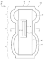
- FIG. 1 is a plan view showing an absorbent article according to the first embodiment of the first invention.
- 2 is a cross-sectional view taken along line X1-X1 shown in FIG.
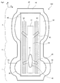
- FIG. 3 is a plan view showing an absorbent article according to the second embodiment of the first invention.
- 4 is a cross-sectional view taken along line X2-X2 shown in FIG.
- FIG. 5 is a cross-sectional view of an absorbent article according to the third embodiment of the first invention.
- FIG. 6 is a plan view showing the absorbent article according to the first embodiment of the second invention.
- FIG. 7 is a cross-sectional view taken along line X3-X3 shown in FIG.
- FIG. 8 is a plan view showing an absorbent article according to the second embodiment of the second invention.
- FIG. 9 is a plan view showing an absorbent article according to the third embodiment of the second invention.
- 10 is a cross-sectional view taken along line X4-X4 shown in FIG.
- the “longitudinal direction” means a direction in the absorbent article that connects the front body located on the wearer's abdomen side and the back body located on the wearer's back side.
- the “width direction” means a direction perpendicular to the longitudinal direction of the absorbent article.
- the longitudinal direction of the absorbent article is indicated by the Y axis
- the width direction of the absorbent article is indicated by the X axis.
- a “skin opposing surface” means the surface which opposes a wearer's skin at the time of wear of an absorbent article.
- the “non-skin facing surface” means a surface that does not face the wearer's skin when the absorbent article is worn.
- FIG. 1 is a plan view showing an absorbent article 100 according to the first embodiment.
- 2 is a cross-sectional view schematically showing a cross-sectional structure of the absorbent article 100 taken along the line X1-X1 shown in FIG.
- FIG. 2 in order to show the configuration of the absorbent article 100 in an easy-to-understand manner, gaps are drawn between various components, but in reality, there are no gaps between the components. Little formed.
- the absorbent article 100 relates to an absorbent pad.
- the absorbent pad can be used alone, or can be used on the inner surface side of a pants-type or tape-type disposable diaper.
- the absorbent article 100 includes a front body 1 located on the wearer's abdomen side, a back body 2 located on the wearer's back side, and a crotch 3 located therebetween. And can be divided in the longitudinal direction.
- the absorbent article 100 has a shape that can be expressed as a gourd type or an hourglass type in a plan view. In other words, the absorbent article 100 has a constricted portion at the crotch 3 which is a portion where the lateral width of the absorbent article 100 is the narrowest.
- the front body 1 and the back body 2 of the absorbent article 100 have side flaps that are portions extending from the constricted portion of the crotch 3 to the left and right outer sides in the width direction. That is, in the portion where the side flaps are formed, the width of the front body 1 and the back body 2 is wider than the width of the constricted portion of the crotch 3.
- the absorbent article 100 can be a gourd type (hourglass type).
- the shape of the absorbent article 100 can be changed as appropriate, for example, a simple rectangular shape.
- the absorbent article 100 basically includes a liquid-permeable top sheet 10, a liquid-impermeable back sheet 20, and a plurality of them interposed therebetween.
- Absorbers 30 and 40 are provided. As shown in the sectional view of FIG. 2, the plurality of absorbers 30 and 40 are stacked in the thickness direction.
- the top sheet 10 covers the skin facing surface side of the laminated absorbent bodies 30 and 40, and the back sheet 20 covers the skin non-facing surface side of the laminated absorbent bodies 30 and 40. .
- the top sheet 10 and the back sheet 20 are joined to each other around the absorbers 30 and 40. As a result, the absorbers 30 and 40 are surrounded by the joint between the top sheet 10 and the back sheet 20.
- the top sheet 10 is a sheet-like member that is in direct contact with the skin of the wearer's inseam and allows liquid such as urine to pass through the absorbers 30 and 40. For this reason, the top sheet 10 is composed of a liquid-permeable material having high flexibility.
- the liquid permeable material constituting the top sheet 10 are a woven fabric, a non-woven fabric, or a porous film.
- a fiber made of a thermoplastic resin such as polypropylene, polyethylene, polyester, or nylon, which has been subjected to a hydrophilization treatment and further made into a non-woven fabric may be used.
- the nonwoven fabric include air-through nonwoven fabric, point bond nonwoven fabric, spunbond nonwoven fabric, and melt blown nonwoven fabric.
- the back sheet 20 is a sheet-like member for preventing liquid that has passed through the top sheet 10 and absorbed by the absorbers 30 and 40 from leaking out of the diaper. For this reason, the backsheet 20 is comprised with a liquid-impermeable material.
- An example of the liquid-impermeable material constituting the backsheet 20 is a liquid-impermeable film made of polyethylene resin.
- the backsheet 20 is preferably a microporous polyethylene film in which a plurality of fine pores of 0.1 to 4 ⁇ m are formed in order to ensure air permeability while maintaining liquid impermeability.
- the absorbers 30 and 40 are members for absorbing a liquid such as urine and holding the absorbed liquid.
- the absorbers 30 and 40 are disposed between the liquid-permeable top sheet 10 and the liquid-impermeable back sheet 20.
- the absorbent article 100 includes two absorbers, an upper layer absorber 30 located on the top sheet 10 side and a lower layer absorber 40 located on the back sheet 20 side.
- Each of the upper layer absorber 30 and the lower layer absorber 40 can be made of a known absorbent material.
- As an absorptive material it is good also as using the fluff pulp formed by crushing fiber materials, such as a conifer, a super absorbent polymer (SAP), and a hydrophilic sheet, for example.
- SAP super absorbent polymer
- hydrophilic sheet for example.
- the absorbent material one kind of fluff pulp, super absorbent polymer, or hydrophilic sheet may be used alone, or two or more kinds may be used in combination.
- the upper layer absorbent body 30 is a combination of fluff pulp and a superabsorbent polymer, and has a configuration in which a plurality of granular superabsorbent polymers are supported by the fluff pulp.
- the lower layer absorber 40 consists only of fluff pulp, and the superabsorbent polymer is not distributed.
- the upper absorbent body 30 located near the skin of the wearer is made to contain the superabsorbent polymer, and the lower absorbent body 40 not containing this superabsorbent polymer is provided. This is a preferred embodiment of the present invention.
- the upper absorbent body 30 contains a superabsorbent polymer
- liquid such as urine can be quickly absorbed by the upper absorbent body 30, so that the surface of the absorbent article 100 is smooth and uncomfortable for the wearer. Can be avoided.
- the lower layer absorber 40 absorbs liquid that could not be absorbed by the upper layer absorber 30.
- the amount of liquid absorbed is more likely to absorb the liquid in a wide range of the lower layer absorber 40 without providing the superabsorbent polymer. It is effective in terms of improving For this reason, in the present embodiment, the superabsorbent polymer is sprayed only on the upper layer absorber 30 and the superabsorbent polymer is not sprinkled on the lower layer absorber 40.
- an upper opening 31 is formed in the upper absorber 30.
- the upper opening 31 is a hole (slit) penetrating in the thickness direction of the upper absorber 30.
- the upper opening 31 is formed at least in a portion of the upper-layer absorber 30 that is easy to directly touch the urine excreted by the wearer at first.
- the upper opening 31 is formed in the crotch 3.
- the upper opening 31 may be formed in a part of the crotch part 3 and extends to the front body 1 and / or the back body 2 beyond the crotch part 3. It may be formed as follows.
- the upper side opening part 31 is located in the center part of the width direction of the crotch part 3.
- the upper opening 31 is positioned at the central part of the crotch part 3. Is preferred.
- the urine excreted by the wearer diffuses in the longitudinal direction along the upper opening 31. Moreover, since the surface area of the upper layer absorber 30 is increased by forming the upper opening 31, a liquid such as urine can be quickly absorbed. Furthermore, liquid such as urine excreted on the upper layer absorber 30 can be guided to the lower layer absorber 40 through the upper opening 31. Thereby, the liquid can be efficiently absorbed by both the upper layer absorber 30 and the lower layer absorber 40.
- the upper opening 31 has a predetermined length L1 (maximum value) and a predetermined lateral width W1 (maximum value).
- the length L1 and the lateral width W1 of the upper opening 31 may be appropriately adjusted according to the size of the absorbent article 100.
- the length L1 of the upper opening 31 may be 100 mm to 300 mm, or 150 mm to 250 mm.
- the lateral width W1 of the upper opening 31 is at least shorter than the length L1, and may be, for example, 5 mm to 35 mm, or 10 mm to 30 mm.
- the upper side opening part 31 becomes a shape long in a longitudinal direction. In the example shown in FIG.
- the upper opening 31 is formed in a rectangular shape extending in the longitudinal direction.
- the shape of the upper opening 31 is not limited to the illustrated one, and various shapes such as a triangle, a pentagon, other polygons, and a circle can be adopted.
- a lower opening 41 is formed in the lower layer absorber 40.
- the lower opening 41 is a hole (slit) penetrating in the thickness direction of the lower layer absorber 40.
- the lower opening 41 has a predetermined length L2 (maximum value) and a predetermined lateral width W2 (maximum value).
- L2 and the width W2 of the lower opening 41 of the lower layer absorber 40 are shorter than the length L1 and the width W1 of the upper opening 31 of the upper layer absorber 30, respectively. (L2 ⁇ L1, W2 ⁇ W1).
- the length L2 of the lower opening 41 is preferably 40% to 95% or 50% to 90% with respect to the length L1 of the upper opening 31.
- the lateral width W2 of the lower opening 41 is preferably 30% to 95% or 40% to 90% with respect to the lateral width W1 of the upper opening 31.
- the opening area of the lower opening 41 is the opening area of the upper opening 31. Smaller than.
- the shape of the lower opening 41 is preferably a rectangular shape similar to the upper opening 31.
- the shape of the lower opening 41 may not be similar to that of the upper opening 31, and various shapes such as a triangle, a pentagon, other polygons, and a circle can be adopted.
- the lower opening 41 of the lower layer absorber 40 is formed at a position at least partially overlapping with the upper opening 31 of the upper layer absorber 30.
- the lower opening 41 preferably overlaps the upper opening 31 as a whole.
- the lower opening 41 may have a portion that does not overlap the upper opening 31.
- the lower opening 41 is such that 50% to 100% or 90% to 100% of the area overlaps with the upper opening 31.
- the liquid excreted by the wearer passes through the upper opening 31 and the lower opening 41. Therefore, the liquid can be absorbed in a wide range of the absorbers 30 and 40.
- the absorbent article 100 is attached to the wearer's crotch, it is considered that the absorbent bodies 30 and 40 are compressed in the width direction.
- each absorber 30, 40 is compressed in the width direction and the lower opening 41 is blocked.
- the space of the upper opening 31 can be maintained.
- liquid such as urine can be guided to the lower layer absorber 40 through the upper opening 31, and the absorbent capacity of the absorbent article can be improved.
- liquids, such as urine are diffused along the upper side opening part 31 of the upper layer absorber 30, and the lower side opening part 41 of the lower layer absorber 40, the liquid diffusibility of the whole absorbent article can be improved.
- the lower opening 41 of the lower layer absorber 40 smaller than the upper opening 31 of the upper layer absorber 30, the liquid that has passed through the upper opening 31 can be easily collected by the lower layer absorber 40. Become.
- the shapes of the upper layer absorber 30 and the lower layer absorber 40 are different. That is, the upper layer absorber 30 is molded into a so-called gourd type or hourglass type, whereas the lower layer absorber 40 is molded into a rectangular shape.
- the shapes of the upper layer absorber 30 and the lower layer absorber 40 can be made different.
- the upper layer absorber 30 has an extending portion 32 that extends more outward in the width direction than the lower layer absorber 40 in the front body 1 and the back body 2 when superimposed on the lower layer absorber 40. Yes. Therefore, in the present embodiment, the upper layer absorber 30 is formed larger than the lower layer absorber 40 by the extension portion 32.
- the upper layer absorber 30 when urine or the like is excreted, it can be quickly absorbed in a wide range of the upper layer absorber 30, which leads to prevention of urine leakage.
- the lower layer absorber 40 disposed below the upper layer absorber 30 may be formed into a gourd shape like the upper layer absorber 30, but the wearing feeling of the absorbent article 100 may be reduced. , Not very preferable. Therefore, as in the present embodiment, the shape of the lower layer absorbent body 40 is a rectangular shape smaller than that of the upper layer absorbent body 30, thereby increasing the amount of absorption of the entire absorbent article 100 and maintaining a good feeling of wear. can do.
- the absorbent article 100 further includes a first diffusion sheet 61, a second diffusion sheet 62, and a third diffusion sheet 63.
- the first diffusion sheet 61 is disposed between the top sheet 10 and the upper layer absorber 30.
- the second diffusion sheet 62 is disposed between the upper layer absorber 30 and the lower layer absorber 40.
- the third diffusion sheet 63 is disposed between the lower layer absorber 40 and the back sheet 20.
- the second diffusion sheet 62 and the third diffusion sheet 63 are composed of a single sheet member, and both are integrally connected so as to enclose the lower layer absorber 40. It has become a thing.
- each of the diffusion sheets 61 to 63 may be composed of separate sheet members, or may be composed of connected sheet members.
- the first diffusion sheet 61, the second diffusion sheet 62, and the third diffusion sheet 63 are sheet-like members having liquid diffusibility capable of absorbing and diffusing liquid.
- Each of the diffusion sheets 61 to 63 may be a thin paper such as tissue paper or a non-woven fabric.
- the nonwoven fabric include air-through nonwoven fabric, point bond nonwoven fabric, spunbond nonwoven fabric, and melt blown nonwoven fabric.
- the first diffusion sheet 61 covers the upper opening 31 of the upper absorbent body 30 from the skin facing surface side.
- the second diffusion sheet 62 covers the upper opening 31 of the upper absorbent body 30 from the skin non-facing surface side, and covers the lower opening 41 of the lower absorbent body 40 from the skin facing surface side.
- the third diffusion sheet 63 covers the lower opening 41 of the lower layer absorber 40 from the skin non-facing surface side.
- the absorbent article 100 further includes an SAP layer 50.
- the SAP layer 50 is formed between the upper layer absorber 30 and the lower layer absorber 40.
- the SAP layer 50 is a layer formed by collecting a plurality of granular superabsorbent polymers (SAP).
- SAP layer 50 is held between the absorbers 30 and 40 by sandwiching a plurality of superabsorbent polymers between the upper absorber 30 and the lower absorber 40.
- a known material may be used as the superabsorbent polymer (SAP).
- SAP superabsorbent polymer
- a highly water-absorbing polymer absorbs liquid about 100 to 1000 times its own weight.
- a polymer having a diameter of about 0.1 mm to 0.5 mm in a dry state before liquid absorption may be employed.
- the SAP layer 50 between the upper layer absorber 30 and the lower layer absorber 40, the liquid guided between the upper layer absorber 30 and the lower layer absorber 40 by the second diffusion sheet 62 is allowed to flow. , The SAP layer 50 can be absorbed quickly. Accordingly, the liquid that has flowed into the upper opening 31 of the upper absorber 30 can be reliably collected by the SAP layer 50 while being diffused over a wide range by the second diffusion sheet 62. Thereby, even if a large amount of liquid is discharged into the central portion of the upper-layer absorber 30 or the upper opening 31, it is possible to prevent the liquid from leaking to the outside.
- the SAP layer 50 is disposed between the upper layer absorber 30 and the lower layer absorber 40, even if the SAP layer 50 absorbs a large amount of liquid and expands its volume, the feel of the SAP layer 50 is felt to the wearer. Difficult to communicate. Therefore, it is possible to provide the wearer with a good wearing feeling that does not change between before and after liquid excretion.
- the SAP layer 50 is formed at least on both the left and right sides in the width direction of the lower opening 41.
- the SAP layer 50 is preferably formed on both the left and right sides of the lower opening 41 in the width direction and on the left and right sides of the upper opening 31 in the width direction.
- the wearer may have a risk of clogging the openings 31 and 41 when the polymer absorbs the liquid, or the rough feel of the superabsorbent polymer. There is a risk of transmission.
- the SAP layer 50 may be formed in the front-back both sides of the longitudinal direction of the upper side opening part 31 or the lower side opening part 41. As shown in FIG.
- the SAP layer 50 is formed between the upper layer absorber 30 and the lower layer absorber 40 and between the second diffusion sheet 62 and the lower layer absorber 40.
- the lower layer absorber 40 is enclosed in a single sheet member formed by connecting the second diffusion sheet 62 and the third diffusion sheet 63.
- the second diffusion sheet 62 positioned between the upper layer absorber 30 and the lower layer absorber 40 partially overlaps with each other.
- the overlapping portion of the second diffusion sheet 62 covers the skin non-facing surface side of the upper opening 31 and the skin facing surface side of the lower opening 41. In this way, the liquid that has flowed into the openings 31 and 41 is obtained by partially overlapping and thickening the second diffusion sheet 62 at the portion where the upper opening 31 and the lower opening 41 are formed. Can be diffused more efficiently.
- FIG. 3 shows a plan view of the absorbent article 100 as in FIG. 4 shows a cross-sectional view taken along line X2-X2 shown in FIG. 3, as in FIG.
- the upper layer absorber 30 and the lower layer absorber 40 have a low density region 71 and a high density region 72. This is different from the first embodiment described above.
- a low density region 71 is formed at least in the crotch 3 of the upper layer absorber 30 and the lower layer absorber 40, and a region other than the low density region 71 is a high density region 72.
- the low density region 71 is a region where the density of the fibers constituting the absorbent bodies 30 and 40 is lower than that of the high density region 72.
- the high density region 72 is a region where the density of the fibers constituting the absorbent bodies 30 and 40 is higher than that of the low density region 71.
- the low density region 71 is formed in the central portion of each absorber 30, 40 in the width direction. Further, the low density region 71 is formed over the entire longitudinal direction of each of the absorbent bodies 30 and 40 from the crotch 3 to the front body 1 and the back body 2. Thus, the low density region 71 is formed at least in the center in the width direction of the crotch 3. Further, an upper opening 31 is formed in the low density region 71 of the upper absorber 30, and a lower opening 41 is formed in the low density region 71 of the lower absorber 40.
- the low density region 71 is formed in the central portion in the width direction of each absorber 30, 40, and the openings 31, 41 are formed in the low density region 71.
- the liquid such as urine excreted by the wearer can be quickly absorbed in the low density region 71 of each absorber 30, 40.
- the openings 31 and 41 extending in the longitudinal direction are formed in the low density region 71, the liquid can be diffused throughout the low density region 71.
- the area other than the low density area 71 is a high density area 72.
- the high density regions 72 are formed on both the left and right sides of the low density region 71 in the width direction, and are divided into two regions with the low density region 71 interposed therebetween. That is, the left and right high-density regions 72 are formed over the entire longitudinal direction of each absorber 30, 40, respectively.
- the upper opening 31 of the upper absorber 30 and the lower opening 41 of the lower absorber 40 are formed only in the low density region 71 and are not formed in the high density region 72. However, it is also possible to form the openings 31 and 41 over both the low density region 71 and the high density region 72.
- the high density region 72 can be formed by pressing the upper layer absorber 30 and the lower layer absorber 40, for example.
- a press device such as a known press roller can be used for pressing the absorbers 30 and 40.
- each absorber 30, 40 becomes difficult to lose its shape.
- the high-density regions 72 on the left and right sides of the low-density region 71, even if each absorber 30, 40 is compressed in the width direction, this low-density region 72 is formed.
- the upper opening 31 and the lower opening 41 formed in the density region 71 are not easily blocked. Thereby, even at the time of wearing, the absorption capacity and liquid diffusibility of each absorber 30,40 can be maintained.
- the upper layer absorber 30 and the lower layer absorber 40 are overlapped.
- the absorbers 30 and 40 are simultaneously pressed to form the high density region 72.
- the thickness of the low density region 71 of the upper layer absorber 30 is indicated by a symbol T1
- the thickness of the high density region 72 of the upper layer absorber 30 is indicated by a symbol T2.
- the thickness T2 of the high density region 72 is thinner than the thickness T1 of the low density region 71 (T2 ⁇ T1).
- the thickness T2 of the high density region 72 is preferably 10% to 90%, and particularly preferably 10% to 50%, with respect to the thickness T1 of the low density region 71.
- the thickness of the low density region 71 may be 10 mm to 20 mm.
- the thickness of the high density region 72 may be 5 mm to 15 mm and is thinner than the low density region 71. It should be noted that the relationship between the thicknesses of the low density region 71 and the high density region 72 of the lower layer absorber 40 can be the same as that of the low density region 71 and the high density region 72 of the upper layer absorber 30 described above.
- the density of the fibers constituting the low density region 71 is preferably 10% to 90% with respect to the density of the fibers constituting the high density region 72, and 10% to 50%. It is particularly preferred that When comparing the densities of the low density region 71 and the high density region 72, test pieces of the low density region 71 and the high density region 72 having the same volume are prepared, and the weights of the respective test pieces may be compared. . For this reason, the unit of density is weight (mg) / volume (cm 3 ). For example, the density of the low density region 71 is preferably 5 to 50 mg / cm 3 .
- the density of the high density region 72 is 20 to 150 mg / cm 3 and is preferably in a range higher than the density of the low density region 71.
- the relationship between the density of the low density region 71 and the high density region 72 of the lower layer absorber 40 can be the same as that of the low density region 71 and the high density region 72 of the upper layer absorber 30 described above.
- the lateral width B1 of the low density region 71 is preferably 20% to 80%, or 30% to 70%, for example, with respect to the entire width (maximum value) of the upper layer absorber 30. .
- a region other than the low density region 71 becomes a high density region 72.
- the lateral width of the low density region 71 of the lower layer absorber 40 is made to coincide with the lateral width of the low density region 71 of the upper layer absorber 30.
- the region other than the low density region 71 becomes the high density region 72.
- the upper opening 31 is preferably formed in the low density region 71.
- the lateral width W1 of the upper opening 31 may be 10% to 90% with respect to the lateral width B1 of the low density region 71, and may be 50% to 90%. preferable.
- the lateral width of the lower opening 41 of the lower layer absorber 40 is narrower than the lateral width of the upper opening 31 of the upper layer absorber 30. Therefore, the lower opening 41 of the lower layer absorber 40 is also accommodated in the low density region 71 of the lower layer absorber 40.
- the low density region 71 and the high density region 72 are formed in both the upper layer absorber 30 and the lower layer absorber 40. It can also be formed only on one of the absorber 30 and the lower layer absorber 40.
- the low density region 71 is a single connected region, but the low density region 71 may be divided into two or more regions. Moreover, the low density area
- region 71 should just be formed in the crotch part 3 at least, and does not need to be formed in the front body 1 and the back body 2.
- FIG. 5 shows a cross-sectional view of the absorbent article 100 as in FIG.
- the absorbent article 100 according to the third embodiment includes a second lower layer absorber 80 in addition to the upper layer absorber 30 and the lower layer absorber 40.
- the absorbent article 100 may have a configuration in which three or more layers of absorbers are interposed between the top sheet 10 and the back sheet 20. That is, the absorbent article 100 according to the third embodiment includes the second lower layer absorber 80 further below the upper layer absorber 30 and the lower layer absorber 40 described above (on the skin non-facing surface side).
- the absorber positioned between the upper layer absorber 30 and the second lower layer absorber 80 is referred to as a first lower layer absorber 40.
- the opening formed in the first lower layer absorber 40 is referred to as a first lower opening 41.
- the second lower layer absorber 80 can basically have the same configuration as the first lower layer absorber 40 described above. That is, as shown in FIG. 5, the second lower layer absorber 80 may have a second lower opening 81 at the center in the width direction. In this case, the second lower opening 81 of the second lower layer absorber 80 is longer than the upper opening 31 of the upper layer absorber 30 and the first lower opening 41 of the first lower layer absorber 40. It is preferable that the width is formed short. That is, it is preferable that the length and the width are narrowed in the order of the upper opening 31, the first lower opening 41, and the second lower opening 81.
- a fourth diffusion sheet 64 is provided between the first lower layer absorber 40 and the second lower layer absorber 80.
- a fifth diffusion sheet 65 is provided between the second lower layer absorber 80 and the back sheet 20.
- the fourth diffusion sheet 64 and the fifth diffusion sheet 65 are composed of a single sheet member and encapsulate the second lower layer absorber 80.
- the fourth diffusion sheet 64 and the fifth diffusion sheet 65 may be composed of separate sheet members.
- the fourth diffusion sheet 64 and the fifth diffusion sheet 65 may be, for example, a thin paper such as tissue paper or a non-woven fabric.
- a second SAP layer 90 is formed between the first lower layer absorber 40 and the second lower layer absorber 80.
- the second SAP layer 90 is a layer formed by collecting a plurality of granular superabsorbent polymers (SAP).
- SAP granular superabsorbent polymers
- the second SAP layer 90 is preferably disposed between the fourth diffusion sheet 64 and the second lower layer absorber 80.
- the second SAP layer 90 is formed on the outer side in the width direction of the second lower opening 81 of the second lower layer absorber 80.
- the second SAP layer 90 is outside in the width direction of the second lower opening 81 of the second lower layer absorber 80 and outside in the width direction of the first lower opening 41 of the first lower layer absorber 40. It is preferable to be formed in the region. Accordingly, the second SAP layer 90 can be sandwiched and held by the first lower layer absorber 40 and the second lower layer absorber 80, and scattering of the highly water-absorbing polymer constituting the second SAP layer 90 can be prevented. .
- the absorbent article 100 according to the present invention can have a configuration in which absorbers are stacked in three or more stages.
- the absorber can be laminated in four or more stages or five or more stages.
- SAP superabsorbent polymers
- SAP has a property that the absorption speed of the liquid is slow, and once the liquid is absorbed, it forms a gel and forms a so-called gel block.
- urine leakage may occur due to the slow absorption rate of SAP when a large amount of urination occurs at one time. is there.
- the liquid may not reach the SAP, and the absorber positioned on the skin facing surface side than the SAP contains a lot of moisture. As a result, there was a risk that the liquid would return from the swollen absorbent body.
- the second invention has a high liquid diffusibility, can absorb urine effectively by SAP, and even when a large amount of urination or repeated urination occurs at once, urine leakage or urine reversion
- An absorbent article capable of preventing the above is provided.
- the inventor provides an SAP layer in which SAPs are densely arranged between a plurality of absorbers, and forms openings in the respective absorbers.
- the SAP layer was arranged.
- the excreted liquid is diffused by the opening and effectively absorbed by the SAP layer.
- a large amount of liquid can be prevented from touching the SAP layer at one time, so that the liquid can effectively penetrate into the SAP layer having a slow absorption rate. Urine leakage and urine reversion can be prevented.
- the absorbent article which concerns on 2nd invention is the liquid-permeable top sheet 10 located in the skin opposing surface side, the liquid-impermeable back sheet 20 located in the skin non-facing surface side, the top sheet 10, and the back sheet And a plurality of absorbent bodies interposed between 20 and stacked in the thickness direction.
- the absorbent article has a longitudinal direction and a width direction orthogonal to the longitudinal direction.
- the plurality of absorbers include at least an upper layer absorber 30 located on the top sheet 10 side and a lower layer absorber 40 located on the back sheet 20 side.
- the upper absorber 30 has an upper opening 31, and the lower absorber 40 has a lower opening 41.
- the lower opening 41 extends in the longitudinal direction of the absorbent article and at least partially overlaps the upper opening 31.
- the absorbent article of the present invention further includes an SAP layer 50 formed by arranging a plurality of superabsorbent polymers SAP between the upper layer absorber 30 and the lower layer absorber 40.
- the SAP layer 50 is formed at least on both the left and right sides in the width direction of the opening penetrating portion 42 where the upper opening 31 and the lower opening 41 overlap.
- the excreted urine is absorbed through these openings. Can be dispersed in the longitudinal direction. Furthermore, by forming the SAP layer 50 on both sides of the opening penetrating portion 42 where at least the upper opening 31 and the lower opening 41 overlap, the liquid diffused by the opening can be efficiently transferred by the SAP layer 50. Absorbed. As a result, even when a large amount of urination is performed at once, the liquid diffuses and is absorbed over a wide range of the SAP layer 50, so that urine leakage can be effectively prevented.
- the SAP layer 50 interposing the SAP layer 50 between the upper layer absorber 30 and the lower layer absorber 40, the liquid that has penetrated into the upper layer absorber 30 and the liquid that has penetrated into the lower layer absorber 40 are transferred to the SAP layer 50. can do.
- the SAP layer 50 that has absorbed the liquid swells and gels, making it difficult to release the liquid, and thus the liquid can be prevented from returning.
- a large amount of liquid can be prevented from touching the SAP layer 50 locally at one time, even the SAP layer 50 having a low liquid absorption rate can absorb a large amount of liquid over a wide range. , Can prevent urine leakage.
- the liquid is efficiently dispersed, so that the liquid can be absorbed over a wide range of the SAP layer 50.
- the SAP layer 50 between the upper layer absorber 30 and the lower layer absorber 40, even if the SAP layer 50 absorbs liquid and the volume expands, the feel is not easily transmitted to the wearer. This leads to a decrease in discomfort.
- the liquid is easily diffused in the longitudinal direction along the lower opening 41, and the SAP layers 50 are formed on both the left and right sides of the lower opening 41 in the width direction. It is possible to effectively prevent urine leakage from the urine.
- the opening penetrating portion 42 is formed on the abdomen side of the wearer from the center in the longitudinal direction.
- the opening penetrating portion 42 is formed at a position near the front body where excreted urine is easy to touch first, so that urine can be easily guided to the upper opening 31 and the lower opening 41. Become.
- the lower opening 41 is preferably longer in the longitudinal direction than the upper opening 31. That is, it is preferable that the lower opening 41 has a part extending to the rear body side in the longitudinal direction and a part extending to the front body side in the longitudinal direction than the upper opening 31.
- the liquid that has flowed into the lower opening 41 through the opening penetrating portion 42 is the skin non-facing surface of the upper absorber 30. Since the liquid is contained on the side, it is possible to more effectively prevent the liquid from returning. Further, once the liquid is confined in the lower opening 41, the liquid does not leak or return even if the SAP layer 50 located on both the left and right sides absorbs the liquid over a relatively long time. . Therefore, it is possible to efficiently absorb the liquid by using the SAP layer 50 having a low absorption rate.
- the lower opening 41 has a wide portion 43 that is wider in the width direction than the upper opening 31 at least in part.
- the liquid can be easily diffused in the width direction through the lower opening 41, and at the same time, The total amount of liquid that can be stored in the opening 41 increases. Thereby, the liquid can be transferred to the SAP layer 50 through the lower opening 41 over a wide range in the width direction.
- a liquid diffusive sheet 63 is disposed between the lower layer absorber 40 and the SAP layer 50 in a region covering the lower opening 41.
- the SAP layer 50 may be formed at least partially at a position overlapping the lower opening 41 in the thickness direction. In this way, by positioning the SAP layer 50 on the liquid diffusive sheet 63, even when the SAP layer 50 and the lower opening 41 overlap, the SAP constituting the SAP layer 50 is located on the lower side. It does not fall into the opening 41.
- the SAP layer 50 can be easily disposed even on the lower opening 41. For this reason, the structure that the lower side opening part 41 is located under the SAP layer 50 is realizable. In this case, the liquid diffusion effect and absorption effect can be further improved by the synergistic effect of the lower opening 41 and the SAP layer 50.
- the diffusibility of the liquid is high, the urine can be effectively absorbed by the SAP, and urine leakage and urine reversion are prevented even when a large amount of urination or repeated urination occurs at one time.
- the absorbent article which can be provided can be provided.
- FIG. 6 is a plan view showing the absorbent article 100 according to the first embodiment.
- FIG. 7 is a cross-sectional view schematically showing a cross-sectional structure of the absorbent article 100 taken along line X3-X3 shown in FIG.
- the absorbent article 100 relates to an absorbent pad.
- the absorbent pad can be used alone, or can be used on the inner surface side of a pants-type or tape-type disposable diaper.
- the absorbent article 100 includes a front body 1 located on the wearer's abdomen side, a back body 2 located on the wearer's back side, and a crotch 3 located therebetween. And can be divided in the longitudinal direction.
- the absorbent article 100 is fundamentally the liquid-permeable top sheet 10, the liquid-impermeable back sheet 20, and the some interposed between these.
- Absorbers 30 and 40 are provided.
- the plurality of absorbers 30 and 40 are stacked in the thickness direction.
- the top sheet 10 covers the skin facing surface side of the laminated absorbent bodies 30 and 40
- the back sheet 20 covers the skin non-facing surface side of the laminated absorbent bodies 30 and 40.
- the top sheet 10 and the back sheet 20 are joined to each other around the absorbers 30 and 40.
- the absorbent article 100 includes two absorbers, an upper layer absorber 30 located on the top sheet 10 side and a lower layer absorber 40 located on the back sheet 20 side.
- Each of the upper layer absorber 30 and the lower layer absorber 40 can be made of a known absorbent material.
- the upper layer absorbent body 30 is a combination of fluff pulp and a superabsorbent polymer, and has a configuration in which a plurality of granular superabsorbent polymers are supported by the fluff pulp.
- the lower layer absorber 40 consists only of fluff pulp, and the superabsorbent polymer is not distributed.
- the upper absorbent body 30 located near the skin of the wearer is made to contain the superabsorbent polymer, and the lower absorbent body 40 not containing this superabsorbent polymer is provided. This is a preferred embodiment of the present invention.
- the upper absorbent body 30 contains a superabsorbent polymer
- liquid such as urine can be quickly absorbed by the upper absorbent body 30, so that the surface of the absorbent article 100 is smooth and uncomfortable for the wearer. Can be avoided.
- the lower layer absorber 40 absorbs liquid that could not be absorbed by the upper layer absorber 30.
- the amount of liquid absorbed is more likely to absorb the liquid in a wide range of the lower layer absorber 40 without providing the superabsorbent polymer. It is effective in terms of improving For this reason, in the present embodiment, the superabsorbent polymer is sprayed only on the upper layer absorber 30 and the superabsorbent polymer is not sprinkled on the lower layer absorber 40.
- an upper opening 31 is formed in the upper absorber 30.
- the upper opening 31 is a hole (slit) penetrating in the thickness direction of the upper absorber 30.
- the upper opening 31 is formed at least in a portion of the upper-layer absorber 30 that is easy to directly touch the urine excreted by the wearer at first.
- the upper opening 31 is preferably formed in a region on the stomach side of the wearer when the upper layer absorbent body 30 is divided into two regions in the longitudinal direction.
- the upper opening 31 is preferably formed at least partially in the front body 1 of the absorbent article 100. In the embodiment shown in FIG.
- the upper opening 31 is formed from the front body 1 to the crotch 3. Further, the upper opening 31 may be formed only in the front body 1 of the absorbent article 100 and may not be formed in the crotch 3 or the back body 2. However, the position of the upper opening 31 may be formed in the crotch 3 or the back body 2 or may be formed in a length from the front body 1 through the crotch 3 to the back body 2. Good. Moreover, it is preferable that the upper side opening part 31 is located in the center part of the width direction. For example, when the upper-layer absorber 30 is equally divided into three regions of the left part, the central part, and the right part in the width direction, the upper opening 31 is preferably located at the center part in the width direction. .
- the upper opening 31 has a predetermined length L1 (maximum value) and a predetermined lateral width W1 (maximum value).
- the length L1 and the lateral width W1 of the upper opening 31 may be appropriately adjusted according to the size of the absorbent article 100.
- the length L1 of the upper opening 31 may be 10 mm to 100 mm, or 20 mm to 60 mm.
- the lateral width W1 of the upper opening 31 is at least shorter than the length L1, and may be, for example, 5 mm to 30 mm, or 10 mm to 20 mm.
- the upper side opening part 31 becomes a shape long in a longitudinal direction. In the example shown in FIG.
- the upper opening 31 is formed in a rectangular shape extending in the longitudinal direction.
- the shape of the upper opening 31 is not limited to the illustrated shape, and various shapes such as a triangle, a pentagon, other polygons, a circle, and an ellipse may be employed.
- a lower opening 41 is formed in the lower layer absorber 40.
- the lower opening 41 is a hole (slit) penetrating in the thickness direction of the lower layer absorber 40.
- the lower opening 41 has a shape extending in the longitudinal direction and is longer than the upper opening 31 in the longitudinal direction. Specifically, the lower opening 41 is longer than the upper opening 31 toward the front end in the longitudinal direction, and is longer than the upper opening 31 toward the rear end in the longitudinal direction. It has the site
- the lower opening 41 has a length extending from the front body 1 to the back body 2 beyond the crotch 3 and extending in the longitudinal direction. Also, as shown in FIG. 6, the lower opening 41 has a wide portion 43 that is partially formed wider in the width direction than the upper opening 31.
- the lower opening 41 has a predetermined length L2 (maximum value) and a predetermined lateral width W2 (maximum value).
- the length L2 and the lateral width W2 of the lower opening 41 of the lower layer absorber 40 are longer than the length L1 and the lateral width W1 of the upper opening 31 of the upper layer absorber 30, respectively.
- L2> L1, W2> W1 the length L2 of the lower opening 41 is preferably 150% to 500%, or 200% to 400% with respect to the length L1 of the upper opening 31.
- the lateral width W2 of the lower opening 41 is preferably 110% to 300%, or 150% to 200% with respect to the lateral width W1 of the upper opening 31.
- the opening area of the lower opening 41 is the opening area of the upper opening 31. Bigger than.
- the shape of the lower opening 41 is preferably a shape in which the lateral width of the wide portion 43 is partially expanded on the basis of a rectangular shape.
- the partial wide portion 43 may be a rectangle, another polygon, or a circle or an ellipse.
- the lower opening 41 of the lower layer absorber 40 is formed at a position at least partially overlapping with the upper opening 31 of the upper layer absorber 30 in the thickness direction.
- a portion where the upper opening 31 and the lower opening 41 overlap in the thickness direction is referred to as an opening penetrating portion 42.
- the lower opening 41 is wider in length and width than the upper opening 31.
- the entire upper opening 31 preferably overlaps the lower opening 41.
- the entire upper opening 31 corresponds to the opening penetrating portion 42 described above.
- the upper opening 31 of the upper-layer absorber 30 is formed in the front body 1, so that the opening through portion 42 where the upper opening 31 and the lower opening 41 overlap is also provided.
- the front body 1 is formed.
- the upper opening 31 may have a portion that does not overlap the lower opening 41.
- the upper opening 31 has 50% to 100% or 90% to 100% of the area overlapping the lower opening 41. It is preferable. In this way, by overlapping a part or all of the upper opening 31 with the lower opening 41, these two openings 31, 41 are communicated in the thickness direction.
- the urine excreted by the wearer is separated from the upper opening 31 and the lower side absorber. It diffuses in the longitudinal direction through the opening 41.
- the lower opening 41 is formed longer in the longitudinal direction than the upper opening 31, the liquid that has flowed into the lower opening 41 through the opening penetrating portion 42 is lower in the lower opening 41. It diffuses in the longitudinal direction of the absorbent article 100 so as to be contained in the absorbent article 100.
- the surface areas of the upper layer absorber 30 and the lower layer absorber 40 are increased by forming the upper opening 31 and the lower opening 41, liquid such as urine can be rapidly absorbed.
- liquid such as urine excreted on the upper layer absorber 30 can be guided to the lower layer absorber 40 through the upper opening 31. Thereby, the liquid can be efficiently absorbed by both the upper layer absorber 30 and the lower layer absorber 40.
- the wide portion 43 of the lower opening 41 overlaps the upper opening 31.
- the wide portion 43 of the lower opening 41 corresponds to the opening penetrating portion 42.
- the shapes of the upper layer absorber 30 and the lower layer absorber 40 are different. That is, the upper layer absorber 30 is molded into a so-called gourd type or hourglass type, whereas the lower layer absorber 40 is molded into a rectangular shape.
- the shapes of the upper layer absorber 30 and the lower layer absorber 40 can be made different.
- the upper layer absorber 30 has an extending portion 32 that extends more outward in the width direction than the lower layer absorber 40 in the front body 1 and the back body 2 when superimposed on the lower layer absorber 40. Yes. Therefore, in the present embodiment, the upper layer absorber 30 is formed larger than the lower layer absorber 40 by the extension portion 32.
- the upper layer absorber 30 when urine or the like is excreted, it can be quickly absorbed in a wide range of the upper layer absorber 30, which leads to prevention of urine leakage.
- the lower layer absorber 40 disposed below the upper layer absorber 30 may be formed into a gourd shape like the upper layer absorber 30, but the wearing feeling of the absorbent article 100 may be reduced. , Not very preferable. Therefore, as in the present embodiment, the shape of the lower layer absorbent body 40 is a rectangular shape smaller than that of the upper layer absorbent body 30, thereby increasing the amount of absorption of the entire absorbent article 100 and maintaining a good feeling of wear. can do.
- the absorbent article 100 includes a first diffusion sheet 61 and a second diffusion sheet 62.
- the first diffusion sheet 61 is disposed between the top sheet 10 and the upper layer absorber 30.
- the second diffusion sheet 62 is disposed between the lower layer absorbent body 40 and the back sheet 20 and has a portion that covers the skin non-facing surface of the lower layer absorbent body 40, and the side of each absorbent body 30, 40. And a portion that covers a part of the skin-facing surface of the upper-layer absorber 30.
- the first diffusion sheet 61 and the second diffusion sheet 62 are overlapped and joined to each other on the left and right sides in the width direction on the skin facing surface side of the upper absorbent body 30.
- first diffusion sheet 61 and the second diffusion sheet 62 are joined to each other so as to enclose the periphery of the upper layer absorber 30 and the lower layer absorber 40.
- the first diffusion sheet 61 and the second diffusion sheet 62 are sheet-like members having liquid diffusibility capable of absorbing and diffusing liquid.
- Each of the diffusion sheets 61 and 62 may be a thin paper such as tissue paper or a non-woven fabric.
- the absorbent article 100 further includes an SAP layer 50.
- the SAP layer 50 is formed between the upper layer absorber 30 and the lower layer absorber 40.
- the SAP layer 50 is a layer formed by collecting a plurality of granular superabsorbent polymers (SAP). Basically, the SAP layer 50 is a layer made of only a superabsorbent polymer.
- the SAP layer 50 is held between the absorbers 30 and 40 by sandwiching a plurality of superabsorbent polymers between the upper absorber 30 and the lower absorber 40.
- the thickness of the SAP layer 50 can be adjusted as appropriate, but may be, for example, about 0.1 mm to 2 mm, or about 0.5 mm to 1.5 mm.
- each of the left and right SAP layers 50 includes not only a portion located on the left and right sides of the opening penetrating portion 42 but also a portion extending to the front end side in the longitudinal direction from the opening penetrating portion 42 and the opening penetrating portion. And a portion extending further to the rear end side in the longitudinal direction than the portion 42.
- the left and right SAP layers 50 are approximately the same length as the lower opening 41 or longer than the lower opening 41, and extend along the left and right sides of the lower opening 41. Is formed.
- the lower opening portion 41 is passed through the opening penetrating portion 42.
- the liquid that has flowed into can be absorbed by the SAP layer 50. More specifically, as described above, since the upper opening 31 and the lower opening 41 are formed in each of the upper absorber 30 and the lower absorber 40, they flow into these openings 31, 41. The liquid is dispersed in the longitudinal direction of the absorbent article. Then, by forming the SAP layer 50 at least on both sides of the opening penetrating portion 42, the liquid diffused by the openings 31 and 41 is efficiently absorbed by the SAP layer 50.
- the urine leakage can be effectively prevented because it is diffused and absorbed over a wide range of the SAP layer 50.
- the SAP layer 50 by interposing the SAP layer 50 between the upper layer absorber 30 and the lower layer absorber 40, the liquid that has penetrated into the upper layer absorber 30 and the liquid that has penetrated into the lower layer absorber 40 are transferred to the SAP layer 50. can do.
- the SAP layer 50 that has absorbed the liquid swells and gels, making it difficult to release the liquid, and thus the liquid can be prevented from returning.
- a large amount of liquid can be prevented from touching the SAP layer 50 locally at one time, even the SAP layer 50 having a low liquid absorption rate can absorb a large amount of liquid over a wide range. , Can prevent urine leakage.
- the SAP layer 50 is formed on both the left and right sides of the lower opening 41 in the width direction. That is, the SAP layer 50 does not overlap the lower opening 41 in the thickness direction.
- the entire SAP layer 50 can be completely sandwiched between the upper layer absorber 30 and the lower layer absorber 40. For this reason, even when the wearer of the absorbent article moves greatly, the superabsorbent polymer constituting the SAP layer 50 can be prevented from falling into the lower opening 41.
- FIG. 8 is a plan view showing the absorbent article 100 according to the second embodiment.
- description of the same configuration as that of the first embodiment described above is omitted, and a configuration different from that of the first embodiment is described.
- the SAP layer 50 is formed only on the left and right sides in the direction. Specifically, since the opening penetrating portion 42 is formed in the front body 1 of the absorbent article 100, the SAP layer 50 is also formed in the front body 1 of the absorbent article 100. In this way, if the SAP layers 50 are formed at least on both the left and right sides of the opening penetrating portion 42 in the width direction, the liquid can be diffused in the longitudinal direction by the lower opening portion 41, and high water absorption is provided around the opening penetrating portion 42. Liquid can be collected by polymer (SAP). For this reason, the SAP layer 50 can efficiently absorb the liquid and prevent its reverse.
- SAPAP polymer
- the upper opening 31 of the upper absorbent body 30 is formed in an elliptical shape.
- the lower opening 41 of the lower layer absorber 40 is formed so that the lateral width thereof is wider than the lateral width of the upper opening 31 as a whole. As described above, the entire lateral width of the lower opening 41 may be formed wider than the lateral width of the upper opening 31.
- FIG. 9 is a plan view showing an absorbent article 100 according to the third embodiment.
- FIG. 10 is a cross-sectional view schematically showing a cross-sectional structure of the absorbent article 100 taken along line X4-X4 shown in FIG.
- the third embodiment will be described focusing on a configuration different from the above-described first embodiment.
- the lower opening 41 includes a base portion 44 extending linearly along the longitudinal direction, and a plurality of base portions 44 extending from the base portion 44 toward the left and right outer sides in the width direction. And a branch portion 45. More specifically, in the present embodiment, the main portion 44 of the lower opening 41 has a longer length in the longitudinal direction than the upper opening 31, and passes from the front body 1 through the crotch 3 to the rear. It is formed with a length that reaches the body 2. Further, the lateral width of the trunk portion 44 of the lower opening 41 is wider than the lateral width of the upper opening 31. In addition, SAP layers 50 are formed on both the left and right sides of the backbone 44 of the lower opening 41.
- the branch portions 45 are formed one by one at the left and right at the position on the front end side in the longitudinal direction, and one by one at the left and right at the position at the rear end side in the longitudinal direction. Is formed. In this manner, the branch portions 45 are formed so as to extend from the trunk portion 44 toward the left and right outer sides in the width direction. For this reason, the branch part 45 overlaps with the SAP layer 50 in the thickness direction at least partially. Further, as shown in FIG. 9, the branch portions 45 are preferably formed on the left and right sides in the width direction of the opening penetrating portion 42 where the upper opening 31 and the lower opening 41 overlap. Thus, by providing the branch portions 45 on the left and right sides of the opening penetrating portion 42, the liquid flowing from the opening penetrating portion 42 can be quickly diffused outward in the width direction.
- FIG. 10 shows a cross-sectional view at a position where the branch portion 45 of the lower opening 41 is formed.
- the SAP layer 50 overlaps the branch portion 45 of the lower opening 41 in the thickness direction. Since the SAP layer 50 is formed by accumulating a plurality of granular superabsorbent polymers (SAP), if the SAP layer 50 overlaps the branch portion 45, the superabsorbent polymer is separated into this amount. There is a risk of falling off the branch 45. Therefore, in the third embodiment, as shown in FIG. 10, a third diffusion having liquid diffusibility is provided so as to cover the lower opening 41 between the SAP layer 50 and the lower layer absorber 40. A sheet 63 is provided.
- the third diffusion sheet 63 is a sheet-like member having liquid diffusibility that can absorb and diffuse liquid.
- the third diffusion sheet 63 may be a thin paper such as tissue paper or a non-woven fabric. Examples of the nonwoven fabric include air-through nonwoven fabric, point bond nonwoven fabric, spunbond nonwoven fabric, and melt blown nonwoven fabric.
- the SAP layer 50 is formed on the third diffusion sheet 63 by providing the third diffusion sheet 63 so as to entirely cover the skin facing surface of the lower layer absorber 40. be able to.
- the superabsorbent polymer constituting the SAP layer 50 is formed in the lower opening of the lower layer absorber 40. It can prevent falling to 41.
- the liquid flowing into the lower opening 41 can be efficiently diffused.
- the absorption capability of the two absorbers 30 and 40 can be utilized effectively.
- the liquid that has flowed into the opening penetrating portion 42 can be reliably collected by the SAP layer 50 while being diffused over a wide range by the third diffusion sheet 63. Thereby, even if a large amount of liquid is discharged to the opening penetrating portion 42, it is possible to prevent the liquid from leaking to the outside.
- the SAP layer 50 is disposed between the upper layer absorber 30 and the lower layer absorber 40, even if the SAP layer 50 absorbs a large amount of liquid and expands its volume, the feel of the SAP layer 50 is felt to the wearer. Difficult to communicate. Therefore, it is possible to provide the wearer with a good wearing feeling that does not change between before and after liquid excretion.
- the branch portion 45 extends from the front side and the rear side of the trunk portion 44 toward the left and right sides.
- the shape of the lower opening 41 is not limited to this, and may be, for example, a Y-shape in which two branch portions 45 extend from the front end or the rear end of the trunk portion 44.
- the example in which the SAP layer 50 is superimposed on the branch portion 45 of the lower opening 41 has been described.
- the SAP layer 50 can be formed so as to overlap the backbone 44 of the lower opening 41. .
- the branch portion 45 of the lower opening 41 overlaps the SAP layer 50 in the thickness direction.
- the basic portion 44 is wider than the region between the left and right SAP layers 50, and the left and right side edges of the basic portion 44 overlap the SAP layer 50 in the thickness direction. May be.
- the branch 45 may not be formed in the lower opening 41. Even in this case, by disposing the third diffusion sheet 63 between the lower opening 41 and the SAP layer 50, the superabsorbent polymer forming the SAP layer 50 is dropped into the lower opening 41. Can be prevented.
- the present invention relates to absorbent articles such as disposable diapers and absorbent pads. Therefore, the present invention can be suitably used in the manufacturing industry for absorbent articles and the like.
Abstract
複数層の吸収体を有する吸収性物品の吸収能力,液拡散性,及び捕集能力を高めることを課題とする。吸収性物品は,肌対向面側に位置する液透過性のトップシート(10)と,肌非対向面側に位置する液不透過性のバックシート(20)と,トップシート(10)とバックシート(20)の間に介在し厚み方向に重ねられた複数の吸収体を備える。複数の吸収体は,少なくとも,トップシート(10)側に位置する上層吸収体(30)と,バックシート(20)側に位置する下層吸収体(40)とを含む。上層吸収体(30)は,長手方向に延び所定の長さ及び幅を持つ上側開口部(31)を有し,下層吸収体(40)は,長手方向に延び上側開口部(31)よりも短い長さ及び幅を持つ下側開口部(41)を有する。上側開口部(31)と下側開口部(41)は,少なくとも部分的に厚み方向に重なっている。
Description
本発明は,着用者の股下に装着され,尿などの液体を吸収し保持するための吸収性物品に関する。
従来から,排泄された体液を吸収保持することを目的として,着用者の股下に装着される吸収性物品が知られている。吸収性物品の例は,使い捨ておむつ,吸収性パッド,及び生理用ナプキンである。また,使い捨ておむつとしては,例えば,前身頃と後身頃の左右両側部が接合されているパンツ型のものや,後身頃に取り付けられた止着テープを前身頃に取り付けて着用されるテープ型ものが知られている。
また,一般的な吸収性物品は,液透過性のトップシートと液不透過性のバックシートとの間に,吸収性繊維と高吸水性ポリマー(SAP)などによって構成された吸収体が設けられている。このような吸収性物品は,吸収体の肌対向面をトップシートによって被覆し,吸収体の肌非対向面をバックシートによって被覆した構成となっている。このため,着用者が排泄した尿などの液体は,トップシートを透過して吸収体に吸収し保持される。また,吸収体に保持されている液体は,吸収体の裏面側に配置された液不透過性のバックシートによって外部に漏洩することが防止されている。
ところで,従来から,吸収性物品を構成する吸収体に,厚み方向に貫通する開口部(スリット)を形成する技術が知られている(特許文献1,特許文献2,特許文献3)。このようなスリットは,液体の拡散性を高めることや,着用者の身体に対するフィット性を高めること,便などの固形物が着用者の肌に長時間触れるのを防止すること,吸収体を屈曲させやすくすることなどの種々の目的で吸収体に形成されている。
例えば,特許文献1には,単層の吸収体に対して,Y字型の開口部を形成する技術が開示されている。また,特許文献2及び特許文献3には,複数の吸収体を厚み方向に重ねて,それぞれの吸収体に開口部を形成する技術が開示されている。特に,特許文献2の吸収性物品は,上層吸収体に上貫通孔を形成するとともに,下層吸収体に下貫通孔を形成し,この上貫通孔と下貫通孔を非重畳的に配置することとしている。また,特許文献3の吸収性物品は,肌対向面側に位置する第1層と肌非対向面側に位置する第2層を設け,第1層には,左右両側にサイドスリットを形成し,第2層には,中央に位置する中央開口とその左右両側に位置するサイドスリットとを形成している。ここで,第1層のサイドスリットと第2層のサイドスリットは,ほぼ同じ長さと同じ幅を有しており,互いに重ねて設けられている。
上記特許文献1から特許文献3に示されるように,吸収体に開口部(スリット)を形成することで,尿などの液体と接触する吸収体の表面積が拡大するため,吸収体の吸収力が向上する。また,液体が吸収体の開口部に沿って拡散するため,吸収体に開口部を設けることで吸収体の液拡散性を向上させることが可能である。また,特許文献2及び特許文献3の吸収性物品のように,吸収体を2層以上に重ねて,上層の吸収体に開口部を設けておくことで,排泄された液体が,上層の吸収体の開口部を通じて,下層の吸収体へと導かれる。これにより,上層の吸収体と下層の吸収体の両方の吸収能力を活用することができると考えられる。従って,開口が形成された複数の吸収体を積層することは,液体の吸収力や液拡散性を高めるという観点において好ましいといえる。
しかしながら,特許文献2の吸収性物品は,上層吸収体の貫通孔と下層吸収体の貫通孔とが非重畳的に配置されおり,着用者によって排泄された液体が上層吸収体の貫通孔を通過しても,下層吸収体の貫通孔に流れ込むような構成にはなっていない。このため,特許文献2の吸収性物品は,下層吸収体の貫通孔が,液体の吸収力向上や液拡散性の向上に寄与するものではなかった。
また,特許文献3の吸収性物品は,吸収体の第1層のサイドスリットと第2層のサイドスリットとを重ねて設けている。このため,特許文献3の吸収性物品においては,着用者によって排泄された液体が,第1層のサイドスリットを通過して,さらに第2層のサイドスリットへと到達する可能性があり,吸収力の向上が期待される。しかしながら,一般的な吸収性物品は,着用者の両脚部の間に挟まれるようにして股下に装着されるものであり,着用者の股下に装着された状態において,幅方向に圧縮されることとなる。この場合に,特許文献3の吸収性物品のように,上層の吸収体の開口と下層の吸収体の開口がほぼ同じ長さ及び幅で形成されていると,着用者の股下に装着されたときに,幅方向への圧縮を受けて,上層と下層の開口部の両方が同時に潰れてしまうおそれがあった。このように,開口部を形成するための空間が潰れてしまうと,上層の吸収体の開口部から下層の吸収体へと液体が流れ落ちにくくなり,下層の吸収体の吸収能力を十分に活かすことができないという問題がある。また,上層の吸収体の開口部が潰れてしまうと,この開口部に沿って液体が拡散しにくくなるため,吸収体全体として液拡散性が低下するという問題がある。
さらに,特許文献3の吸収性物品のように,上側と下側の開口部がほぼ同じ長さ及び幅で形成されていると,上層の開口部に流れ込んだ液体が,下層の吸収体によって捕集されずに,下層の開口部をそのまま通過してバックシートに到達することがある。このような場合,下層の吸収体によって,着用者が排泄した液体を効率的に捕集することができないという問題があった。
このため,現在では,開口部が形成された複数層の吸収体を有する吸収性物品において,各層の吸収体の吸収能力,液拡散性,及び捕集能力を効率的に活用するための技術が求められている。
本発明の発明者らは,従来の課題の解決手段について鋭意検討した結果,開口部が形成された複数層の吸収体を有する吸収性物品において,上層吸収体の開口部を下層吸収体の開口部よりも大きく形成し,且つ,上層と下層の開口部を重畳的に配置することとした。このように,比較的大きい上層の開口部と比較的小さい下層の開口部を少なくとも部分的に重ねて配置することで,各層の吸収体の吸収能力,液拡散性,及び捕集能力を効率的に活用することができるという知見を得た。そして,本発明者らは,上記知見に基づけば,従来技術の課題を解決できることに想到し,本発明を完成させた。具体的に説明すると,本発明は以下の構成を有する。
本発明は,使い捨ておむつや吸収性パッドなどの吸収性物品に関する。
本発明の吸収性物品は,装着時において着用者の腹側に位置する前身頃1と着用者の背側に位置する後身頃2の間に位置する股下部3を有している。
本発明の吸収性物品は,肌対向面側に位置する液透過性のトップシート10と,肌非対向面側に位置する液不透過性のバックシート20と,これらのトップシート10とバックシート20の間に介在して厚み方向に重ねられた複数の吸収体と,を備える。
ここで,複数の吸収体は,少なくとも,トップシート10側に位置する上層吸収体30と,バックシート20側に位置する下層吸収体40と,を含む。
上層吸収体30は,長手方向に延び,所定の長さ及び幅を持つ上側開口部31を有している。また,下層吸収体40は,長手方向に延び,上側開口部31よりも短い長さ及び幅を持つ下側開口部41を有している。
そして,上側開口部31と下側開口部41は,少なくとも部分的に厚み方向に重なっている。
上記構成のように,上層吸収体30の上側開口部31と下層吸収体40の下側開口部41とを重ねることにより,着用者の排泄した液体が,上側開口部31を通じて下側開口部41へと導かれるため,各吸収体の広い範囲で液体を吸収することが可能となる。また,上側開口部31を下側開口部41よりも大きく形成することで,吸収性物品の装着時に,上層吸収体30と下層吸収体40とが幅方向に圧縮されて下側開口部41が塞がってしまう場合でも,上側開口部31を広げておくことができる。これにより,吸収性物品が装着された状態であっても,上側開口部31を通じて,尿などの液体を下層吸収体40へと導くことができるため,吸収性物品の吸収能力を向上させることができる。また,尿などの液体は上層吸収体30の上側開口部31と下層吸収体40の下側開口部41に沿って拡散されるため,吸収性物品全体の液拡散性を高めることができる。さらに,上層吸収体30の上側開口部31よりも下層吸収体40の下側開口部41を小さくしておくことで,上側開口部31を抜けた液体が,下層吸収体40によって捕集されやすくなる。つまり,排泄された液体が,上側開口部31と下側開口部41の両方を抜けて,吸収体によって捕集されずにバックシート20へと到達する可能性を低く抑えることができる。従って,上記構成によれば,吸収性物品の吸収能力,液拡散性,及び捕集能力を向上させることができる。
本発明の吸収性物品において,上層吸収体30と下層吸収体40の間には,液拡散性シートが配置されていることが好ましい。特に,この液拡散性シートは,上層吸収体30の上側開口部31と下層吸収体40の下側開口部41の間に位置していることが好ましい。また,上側開口部31と下側開口部41の間において液拡散性シートには開口部が形成されていないことが好ましい。
上記構成のように,開口部31,41が形成された各吸収体30,40の間に液拡散性シートを配置しておくことで,上層吸収体30によって吸収された液体や上側開口部31を通過した液体が,液拡散性シートによって広い範囲に拡散される。これにより,上層吸収体30と下層吸収体40が持つ吸収能力を効率良く活用することが可能になる。
本発明の吸収性物品は,SAP層50をさらに備えることが好ましい。このSAP層50は,上層吸収体30と下層吸収体40の間に複数の高吸水性ポリマー(SAP)が配置されることにより形成された層である。
この場合に,SAP層50は,少なくとも,下側開口部41の幅方向の左右両側に形成されていることが好ましい。
この場合に,SAP層50は,少なくとも,下側開口部41の幅方向の左右両側に形成されていることが好ましい。
上記構成のように,上層吸収体30と下層吸収体40の間にSAP層50を設けておくことで,液拡散性シートによって拡散された液体を迅速に吸収することができる。また,SAP層50を,上層吸収体30と下層吸収体40の間に配置することで,液体を吸収して体積が膨張しても,その感触が着用者に伝わりにくくなる。
本発明の吸収性物品において,SAP層50は,下側開口部41の幅方向の左右両側であって,上側開口部31と厚み方向に重ならない領域に形成されていることが好ましい。
上記構成のように,SAP層50を上層吸収体30の上側開口部31と重ならない位置に配置することで,このSAP層50を上層吸収体30と下層吸収体40とによって挟み込んで固定することができる。このため,吸収性物品の着用者が動いたりしても,SAP層50を構成する高吸水性ポリマーが,上側開口部31や下側開口部41の中に入り込むことを防止できる。すなわち,高吸水性ポリマーが開口部31,41の中に入り込むと,このポリマーが液体を吸収したときに開口部31,41を塞いでしまい,吸収体30,40の液拡散性を損なうおそれがある。また,これらの開口部31,41には吸収体30,40を構成する繊維材料などが配置されていないため,高吸水性ポリマーが開口部31,41に入り込むと,高吸水性ポリマーのざらざらとした感触が着用者に伝わってしまい,肌触りが良くないものとなる。従って,高吸水性ポリマーが開口部31,41内に脱落することを防止するために,SAP層50を上層吸収体30の上側開口部31と重ならない位置に配置することが好ましい。
本発明の吸収性物品において,上層吸収体30と下層吸収体40の両方又はいずれか一方は,低密度領域71と高密度領域72を有するものであることが好ましい。低密度領域71とは,上側開口部31又は下側開口部41の幅方向の左右両側において,吸収体を構成する繊維の密度が比較的低くなっている領域である。高密度領域72とは,低密度領域71の幅方向の左右外側において,吸収体を構成する繊維の密度が比較的高くなっている領域である。
上記構成のように,上層吸収体30や下層吸収体40の幅方向の外側に高密度領域72を形成することで,吸収体30,40の保型性が高まる。このため,上層吸収体30や下層吸収体40を積み重ねても,各吸収体30,40が位置ずれを起こしにくくすることができる。また,着用時には吸収体は着用者の両脚に挟まれる事により圧縮され,さらに前後方向に動かされることになるが,吸収体の保型性を高くすることでマットが割れる現象を起こりにくくすることができる。ただし,吸収体30,40の全体の繊維密度を高くしてしまうと,吸収体30,40の吸収能力や液拡散性が低下するおそれがある。そこで,本発明の好ましい形態では,上側開口部31や下側開口部41が形成されている幅方向の中央付近において,上層吸収体30や下層吸収体40の繊維密度を低くし,吸収能力や液拡散性を維持している。これにより,上層吸収体30と下層吸収体40の吸収性能と保型性を両立させることができる。
本発明によれば,開口部が形成された複数層の吸収体を有する吸収性物品において,各層の吸収体の吸収能力,液拡散性,及び捕集能力を効率的に活用することができる。
以下,図面を用いて本発明を実施するための形態について説明する。本発明は,以下に説明する形態に限定されるものではなく,以下の形態から当業者が自明な範囲で適宜変更したものも含む。
本願明細書において,「A~B」とは,「A以上B以下」であることを意味する。
また,本願明細書において,「長手方向」とは,吸収性物品のうち,着用者の腹部側に位置する前身頃と着用者の背部側に位置する後身頃とを結ぶ方向を意味する。また,「幅方向」とは,吸収性物品の長手方向に平面的に直交する方向を意味する。本願の図において,吸収性物品の長手方向はY軸で示されており,吸収性物品の幅方向はX軸で示されている。
また,本願明細書において,「肌対向面」とは,吸収性物品の着用時において着用者の肌に対向する面を意味する。また,「肌非対向面」とは,吸収性物品の着用時において着用者の肌に対向しない面を意味している。
また,本願明細書において,「長手方向」とは,吸収性物品のうち,着用者の腹部側に位置する前身頃と着用者の背部側に位置する後身頃とを結ぶ方向を意味する。また,「幅方向」とは,吸収性物品の長手方向に平面的に直交する方向を意味する。本願の図において,吸収性物品の長手方向はY軸で示されており,吸収性物品の幅方向はX軸で示されている。
また,本願明細書において,「肌対向面」とは,吸収性物品の着用時において着用者の肌に対向する面を意味する。また,「肌非対向面」とは,吸収性物品の着用時において着用者の肌に対向しない面を意味している。
[1.第1発明について]
[1-1.第1の実施形態]
まず,図1及び図2を参照して,第1発明に係る吸収性物品100の第1の実施形態について説明する。図1は,第1の実施形態に係る吸収性物品100を示した平面図である。また,図2は,図1に示したX1-X1線における吸収性物品100の断面構造を模式的に示した断面図である。なお,図2の断面図において,吸収性物品100の構成を分かりやすく示すために,各種の構成部材の間に隙間を設けて描画しているが,実際には構成部材の間には隙間はほとんど形成されない。
[1-1.第1の実施形態]
まず,図1及び図2を参照して,第1発明に係る吸収性物品100の第1の実施形態について説明する。図1は,第1の実施形態に係る吸収性物品100を示した平面図である。また,図2は,図1に示したX1-X1線における吸収性物品100の断面構造を模式的に示した断面図である。なお,図2の断面図において,吸収性物品100の構成を分かりやすく示すために,各種の構成部材の間に隙間を設けて描画しているが,実際には構成部材の間には隙間はほとんど形成されない。
本実施形態に係る吸収性物品100は,吸収性パッドに関する。吸収性パッドは,単独でも使用することもできるし,パンツ型やテープ型の使い捨ておむつの内面側に重ねて使用することも可能である。図1に示されるように,吸収性物品100は,着用者の腹部側に位置する前身頃1と,着用者の背部側に位置する後身頃2と,これらの間に位置する股下部3とに,長手方向に区分することができる。具体的に説明すると,吸収性物品100は,その平面視において,ひょうたん型若しくは砂時計型と表現することのできる形状となっている。すなわち,吸収性物品100は,股下部3に,吸収性物品100の横幅が最も狭くなった部位であるくびれ部が存在する。他方で,吸収性物品100の前身頃1と後身頃2には,股下部3のくびれ部よりも幅方向の左右外側に延出する部位であるサイドフラップが存在する。つまり,サイドフラップが形成された部分において,前身頃1と後身頃2の横幅は,股下部3のくびれ部における横幅よりも広く形成されている。このように,吸収性物品100はひょうたん型(砂時計型)とすることができる。ただし,吸収性物品100の形状は適宜変更することができ,例えば単純な矩形状とすることも可能である。
また,図1及び図2に示されるように,吸収性物品100は,基本的に,液透過性のトップシート10と,液不透過性のバックシート20と,これらの間に介在する複数の吸収体30,40を有している。図2の断面図に示されるように,複数の吸収体30,40は厚み方向に重ねられている。また,トップシート10は,積層された吸収体30,40の肌対向面側を被覆しており,バックシート20は,積層された吸収体30,40の肌非対向面側を被覆している。図1及び図2に示されるように,吸収体30,40の周囲においては,トップシート10とバックシート20が互いに接合されている。これにより,吸収体30,40は,トップシート10とバックシート20の接合部によって周囲を囲われたものとなる。
トップシート10は,着用者の股下の肌に直接接し,尿などの液体を吸収体30,40へ透過させるためのシート状の部材である。このため,トップシート10は,柔軟性が高い液透過性材料で構成される。トップシート10を構成する液透過性材料の例は,織布,不織布,又は多孔性フィルムである。また,例えばポリプロピレンやポリエチレン,ポリエステル,ナイロンのような熱可塑性樹脂の繊維を親水化処理してさらに不織布にしたものを用いることとしてもよい。不織布としては,エアスルー不織布,ポイントボンド不織布,スパンボンド不織布,メルトブロー不織布などを挙げることができる。
バックシート20は,トップシート10を透過して吸収体30,40に吸収された液体が,おむつの外部へ漏出することを防止するためのシート状の部材である。このため,バックシート20は,液不透過性材料によって構成される。バックシート20を構成する液不透過材料の例は,ポリエチレン樹脂からなる液不透過性のフィルムである。特に,バックシート20としては,液不透過性を維持しつつ通気性を確保するために,0.1~4μmの微細な孔が複数形成された微多孔性ポリエチレンフィルムを用いることが好ましい。
吸収体30,40は,尿などの液体を吸収し,吸収した液体を保持するための部材である。吸収体30,40は,液透過性のトップシート10と,液不透過性のバックシート20の間に配置される。本実施形態に係る吸収性物品100は,トップシート10側に位置する上層吸収体30とバックシート20側に位置する下層吸収体40との2つの吸収体を備えている。上層吸収体30と下層吸収体40は,それぞれ,公知の吸収性材料により構成することができる。吸収性材料としては,例えば,針葉樹などの繊維材料を解砕してなるフラッフパルプや,高吸水性ポリマー(SAP),親水性シートを用いることとしてもよい。また,吸収性材料には,フラッフパルプ,高吸水性ポリマー,又は親水性シートのうち1種類を単独で用いてもよいし,2種類以上を組合せて併用することとしてもよい。
本実施形態において,上層吸収体30は,フラッフパルプと高吸水性ポリマーを組み合わせたものであり,複数の粒状の高吸水性ポリマーがフラッフパルプによって担持された構成となっている。他方で,下層吸収体40は,フラッフパルプのみからなり,高吸水性ポリマーは分布していない。このように,複数の吸収体のうち,少なくとも着用者の肌に近い位置に位置する上層吸収体30に高吸水性ポリマーを含有させるとともに,この高吸水性ポリマーを含有しない下層吸収体40を設けることが,本発明の好ましい形態である。上層吸収体30が高吸水性ポリマーを含むものであることにより,尿などの液体をこの上層吸収体30によって迅速に吸収することができるため,吸収性物品100の表面がサラサラし,着用者に不快感を与えることを回避できる。他方,下層吸収体40においては,上層吸収体30によって吸収しきれなかった液体を吸収することになる。このとき,下層吸収体40に高吸水性ポリマーを設けて吸収速度を高めるよりは,むしろ高吸水性ポリマーを設けずに下層吸収体40の広い範囲で液体を吸収する方が,液体の吸収量を向上させるという観点において効果的である。このため,本実施形態では,上層吸収体30にのみ高吸水性ポリマーを散布し,下層吸収体40には敢えて高吸水性ポリマーを散布しない構成となっている。
図1及び図2に示されるように,本発明において,上層吸収体30には上側開口部31が形成されている。上側開口部31は,上層吸収体30の厚み方向に貫通した孔(スリット)である。上側開口部31は,少なくとも,上層吸収体30のうち,着用者が排泄した尿に最初に直接触れやすい部位に形成される。具体的には,図1に示されるように,上側開口部31は股下部3に形成される。例えば,上側開口部31は,股下部3内の一部分に形成されたものであってもよいし,股下部3を超えて前身頃1及び後身頃2の両方又はいずれか一方にまで延出するように形成されていてもよい。また,上側開口部31は,股下部3の幅方向の中心部分に位置していることが好ましい。例えば,股下部3を,幅方向に,左部分,中央部分,及び右部分の3つの領域に等分した場合に,上側開口部31は,この股下部3の中央部分に位置していることが好ましい。
上記のように,上層吸収体30の股下部3に上側開口部31を形成することで,着用者によって排泄された尿が,この上側開口部31に沿って長手方向に拡散する。また,上側開口部31を形成することで上層吸収体30の表面積が増えるため,尿などの液体を迅速に吸収することができる。さらに,上層吸収体30上に排泄された尿などの液体を,上側開口部31を通じて,下層吸収体40へと導くことができる。これにより,上層吸収体30と下層吸収体40の両方によって,液体を効率的に吸収することが可能になる。
図1及び図2に示されるように,上側開口部31は,所定の長さL1(最大値)と所定の横幅W1(最大値)を有している。上側開口部31の長さL1と横幅W1は,吸収性物品100の大きさに合わせて適宜調節すればよい。例えば,吸収性物品100が大人用の吸収性パッドである場合,上側開口部31の長さL1は,100mm~300mm,又は150mm~250mmとすればよい。また,上側開口部31の横幅W1は,少なくとも長さL1よりも短いものであって,例えば,5mm~35mm,又は10mm~30mmとすればよい。このように,上側開口部31は,長手方向に長い形状となる。図1に示された例において,上側開口部31は,長手方向に延びる長方形状に形成されている。ただし,上側開口部31の形状は,図示されたものに限られず,例えば三角形や,五角形,その他の多角形,円形など種々の形状を採用することも可能である。
また,図1及び図2に示されるように,本発明において,下層吸収体40には下側開口部41が形成されている。下側開口部41は,下層吸収体40の厚み方向に貫通した孔(スリット)である。下側開口部41は,所定の長さL2(最大値)と所定の横幅W2(最大値)を有している。ここで,図に示されるように,下層吸収体40の下側開口部41の長さL2と横幅W2は,それぞれ,上層吸収体30の上側開口部31の長さL1と横幅W1よりも短くなっている(L2<L1,W2<W1)。例えば,下側開口部41の長さL2は,上側開口部31の長さL1に対して,40%~95%,又は50%~90%であることが好ましい。また,下側開口部41の横幅W2は,上側開口部31の横幅W1に対して,30%~95%,又は40%~90%であることが好ましい。このように,下側開口部41の長さ及び横幅が上側開口部31の長さ及び横幅よりも短いため,基本的に,下側開口部41の開口面積は,上側開口部31の開口面積よりも小さくなる。図1に示されるように,下側開口部41の形状は,上側開口部31と相似となる長方形状であることが好ましい。ただし,下側開口部41の形状は,上側開口部31と相似形でなくてもよく,三角形や,五角形,その他の多角形,円形など種々の形状を採用することができる。
また,下層吸収体40の下側開口部41は,上層吸収体30の上側開口部31と少なくとも部分的に重畳する位置に形成されている。特に,図1に示されるように,下側開口部41は,その全体が,上側開口部31に重なっていることが好ましい。ただし,下側開口部41は,上側開口部31と重ならない部分を有していてもよい。例えば,下側開口部41の全体の面積を100%とした場合に,下側開口部41は,その面積の50%~100%又は90%~100%が,上側開口部31と重なるものであることが好ましい。このように,下側開口部41の一部又は全部を上側開口部31と重ねることで,これらの2つの開口部31,41が連通するようになる。
上記のように,上層吸収体30の上側開口部31と下層吸収体40の下側開口部41とを連通させることで,着用者の排泄した液体が,上側開口部31を通じて下側開口部41へと導かれるため,各吸収体30,40の広い範囲で液体を吸収することができる。また,吸収性物品100が着用者の股下に装着されると,各吸収体30,40が幅方向に圧縮されると考えられる。このとき,上側開口部31を下側開口部41よりも大きく形成しておくことで,各吸収体30,40が幅方向に圧縮されて下側開口部41が塞がってしまった場合であっても,上側開口部31の空間を維持することができる。これにより,吸収性物品の装着時にも,上側開口部31を通じて,尿などの液体を下層吸収体40へと導くことができ,吸収性物品の吸収能力を向上させることができる。また,尿などの液体は上層吸収体30の上側開口部31と下層吸収体40の下側開口部41に沿って拡散されるため,吸収性物品全体の液拡散性を高めることができる。さらに,上層吸収体30の上側開口部31よりも下層吸収体40の下側開口部41を小さくしておくことで,上側開口部31を抜けた液体を,下層吸収体40によって捕集しやすくなる。
図1及び図2に示されるように,本実施形態において,上層吸収体30と下層吸収体40の形状は異なっている。つまり,上層吸収体30は,いわゆるひょうたん型又は砂時計型に成型されているのに対し,下層吸収体40は,長方形状に成型されている。このように,上層吸収体30と下層吸収体40の形状を異ならせることもできる。特に,上層吸収体30は,下層吸収体40上に重ねたときに,前身頃1及び後身頃2において,この下層吸収体40よりも幅方向外側に向かって広がる延出部32を有している。従って,本実施形態において,上層吸収体30は,延出部32の分だけ,下層吸収体40よりも大きく形成されている。このように,上層吸収体30のサイズを大きくすることで,尿などが排泄されたときに,この上層吸収体30の広い範囲で迅速に吸収することができるため,尿漏れの防止に繋がる。また,上層吸収体30の下方に配置する下層吸収体40も,上層吸収体30と同様に,ひょうたん型に成型することも考えられるが,吸収性物品100の着用感が低下するおそれがあるため,あまり好ましくはない。そこで,本実施形態のように,下層吸収体40の形状は上層吸収体30よりも小さい長方形状としておくことで,吸収性物品100全体の吸収量を増加させるととともに,着用感を良好に維持することができる。
図2の断面図に示されるように,本実施形態に係る吸収性物品100は,第1拡散シート61,第2拡散シート62,及び第3拡散シート63を,さらに備えている。図2に示されるように,第1拡散シート61は,トップシート10と上層吸収体30の間に配置されている。また,第2拡散シート62は,上層吸収体30と下層吸収体40の間に配置されている。また,第3拡散シート63は,下層吸収体40とバックシート20の間に配置されている。本実施形態において,第2拡散シート62と第3拡散シート63は,一枚のシート部材から構成されたものあり,両者は,下層吸収体40の周囲を被包するように一体的に繋がったものとなっている。このように,各拡散シート61~63は,それぞれ別々のシート部材から構成されたものであってもよいし,繋がったシート部材から構成されていてもよい。
第1拡散シート61,第2拡散シート62,及び第3拡散シート63は,液体を吸収して拡散可能な液拡散性を有するシート状の部材である。各拡散シート61~63は,例えば,ティッシュペーパのような薄葉紙であってもよいし,不織布であってもよい。不織布としては,エアスルー不織布,ポイントボンド不織布,スパンボンド不織布,メルトブロー不織布などを挙げることができる。
図2に示されるように,第1拡散シート61は,上層吸収体30の上側開口部31を肌対向面側から被覆している。また,第2拡散シート62は,上層吸収体30の上側開口部31を肌非対向面側から被覆するとともに,下層吸収体40の下側開口部41を肌対向面側から被覆している。さらに,第3拡散シート63は,下層吸収体40の下側開口部41を肌非対向面側から被覆している。このように,それぞれの開口部31,41を含めて,各吸収体30,40を液拡散性のシート部材によって被覆することで,開口部31,41に流れ込む液体を効率的に拡散させることができる。これにより,2つの吸収体30,40の広い範囲で液体が吸収されるため,2つの吸収体30,40の吸収能力を効果的に活用することができる。特に,上層吸収体30と下層吸収体40の隙間には液体が浸透しにくい。そこで,上層吸収体30と下層吸収体40の隙間に第2拡散シート62を設けることで,通常であれば液体を吸収しにくいとされる上層吸収体30と下層吸収体40の隙間の領域にも液体を浸透させることができる。
図2の断面図に示されるように,本実施形態に係る吸収性物品100は,さらに,SAP層50を有する。このSAP層50は,上層吸収体30と下層吸収体40の間に形成されている。SAP層50は,複数の粒状の高吸水性ポリマー(SAP)が集まることによって形成された層である。SAP層50は,複数の高吸水性ポリマーが上層吸収体30と下層吸収体40によって挟み込まれることで,これらの吸収体30,40の間に保持されている。高吸水性ポリマー(SAP)としては公知の素材を用いればよい。例えば,高吸水性ポリマーは,自重の100倍~1000倍程度の液体を吸収する。高吸水性ポリマーとしては,例えば,液体の吸収前の乾燥状態において0.1mm~0.5mm程度の直径を有するものを採用すればよい。
上記のように,上層吸収体30と下層吸収体40の間にSAP層50を設けておくことで,第2拡散シート62によって上層吸収体30と下層吸収体40の間に導かれた液体を,このSAP層50によって迅速に吸収することができる。従って,上層吸収体30の上側開口部31に流れ込んだ液体を,第2拡散シート62によって広い範囲に拡散させながら,SAP層50によって確実に捕集できる。これにより,上層吸収体30の中央部分や上側開口部31の中に大量の液体が排出されても,その液体が外部に漏洩することを防止することが可能である。また,SAP層50は,上層吸収体30と下層吸収体40の間に配置されているため,このSAP層50が大量の液体を吸収して体積が膨張しても,その感触が着用者に伝わりにくい。従って,液体の排泄前と排泄後とで変わらない良好な装着感を,着用者に提供できる。
また,SAP層50は,少なくとも,下側開口部41の幅方向の左右両側に形成されている。特に,SAP層50は,下側開口部41の幅方向の左右両側であって,且つ,上側開口部31の幅方向の左右両側に形成されていることが好ましい。このように,SAP層50を上側開口部31と下側開口部41の両方に重ならない範囲に設けることで,SAP層50全体を完全に上層吸収体30と下層吸収体40とによって挟み込むことができる。このため,吸収性物品の着用者が大きく動いたような場合であっても,SAP層50を構成する高吸水性ポリマーが,上側開口部31や下側開口部41の中に脱落することを防止できる。高吸水性ポリマーが開口部31,41の中に脱落すると,このポリマーが液体を吸収したときに開口部31,41を塞いでしまうおそれや,高吸水性ポリマーのざらざらとした感触が着用者に伝わるおそれがある。この点,SAP層50を上側開口部31と下側開口部41の両方に重ならない範囲に設けることで,高吸水性ポリマーが開口部31,41内に脱落することをより確実に防止できる。なお,図示は省略するが,SAP層50は,上側開口部31や下側開口部41の長手方向の前後両側に形成されていてもよい。
また,図2に示されるように,SAP層50は,上層吸収体30と下層吸収体40の間であって,且つ,第2拡散シート62と下層吸収体40の間に形成されていることが好ましい。特に,本実施形態において,下層吸収体40は,第2拡散シート62と第3拡散シート63を連結してなる一枚のシート部材の内部に封入されている。このような場合に,第2拡散シート62と第3拡散シート63から構成される一枚のシート部材の中に,下層吸収体40と共に,SAP層50を封入しておくことが好ましい。これにより,万が一,SAP層50を構成する高吸水性ポリマーが,下層吸収体40の下側開口部41内に脱落した場合であっても,その高吸水性ポリマーが周りに散乱してしまうという事態を回避できる。また,第2拡散シート62の下方にSAP層50を形成しておくことで,第2拡散シート62に浸透した液体がSAP層50に移りやすくなるため,より効率的にSAP層50によって液体を吸収することが可能となる。
また,図2に示されるように,本実施形態において,上層吸収体30と下層吸収体40の間に位置する第2拡散シート62は,部分的に2重に重なっている。この場合に,第2拡散シート62の重畳部分が,上側開口部31の肌非対向面側と,下側開口部41の肌対向面側を被覆していることが好ましい。このように,上側開口部31及び下側開口部41が形成されている部位において,第2拡散シート62を部分的に重ねて厚くしておくことで,各開口部31,41に流れ込んだ液体をより効率的に拡散させることができる。
[1-2.第2の実施形態]
続いて,図3及び図4を参照して,第1発明に係る吸収性物品100の第2の実施形態について説明する。第2の実施形態については,上述した第1の実施形態と同じ構成については説明を省略し,第1の実施形態と異なる構成を中心に説明を行う。図3は,図1と同様に,吸収性物品100の平面図を示している。また,図4は,図2と同様に,図3に示したX2-X2線における断面図を示している。図3及び図4に示されるように,第2の実施形態に係る吸収性物品100は,上層吸収体30と下層吸収体40とが,低密度領域71と高密度領域72とを有している点において,上述した第1の実施形態と異なっている。
続いて,図3及び図4を参照して,第1発明に係る吸収性物品100の第2の実施形態について説明する。第2の実施形態については,上述した第1の実施形態と同じ構成については説明を省略し,第1の実施形態と異なる構成を中心に説明を行う。図3は,図1と同様に,吸収性物品100の平面図を示している。また,図4は,図2と同様に,図3に示したX2-X2線における断面図を示している。図3及び図4に示されるように,第2の実施形態に係る吸収性物品100は,上層吸収体30と下層吸収体40とが,低密度領域71と高密度領域72とを有している点において,上述した第1の実施形態と異なっている。
図3及び図4に示されるように,上層吸収体30と下層吸収体40うち,少なくとも股下部3に低密度領域71が形成され,この低密度領域71以外の領域が高密度領域72となっている。低密度領域71は,各吸収体30,40を構成する繊維の密度が高密度領域72よりも低い領域である。また,高密度領域72は,各吸収体30,40を構成する繊維の密度が低密度領域71よりも高い領域である。
具体的に説明すると,本実施形態において,低密度領域71は,各吸収体30,40の幅方向の中央部分に形成されている。また,低密度領域71は,股下部3を中心に前身頃1及び後身頃2にかけて,各吸収体30,40の長手方向全体に亘って形成されている。このように,低密度領域71は,少なくとも,股下部3の幅方向中央部分に形成されている。また,上層吸収体30の低密度領域71には上側開口部31が形成され,下層吸収体40の低密度領域71には下側開口部41が形成されている。
このように,本発明の好ましい実施形態では,各吸収体30,40の幅方向の中央部分に低密度領域71を形成し,この低密度領域71に各開口部31,41を形成する。これにより,着用者が排泄した尿などの液体を,各吸収体30,40の低密度領域71において迅速に吸収することができる。しかも,この低密度領域71には長手方向に延びる開口部31,41が形成されているため,低密度領域71全体に液体を拡散させることができる。
他方,低密度領域71以外の領域は,高密度領域72となっている。本実施形態において,高密度領域72は,低密度領域71の幅方向の左右両側に形成されており,低密度領域71を挟んで2つの領域に分かれている。すなわち,左右の高密度領域72は,それぞれ,各吸収体30,40の長手方向全体に亘って形成されている。本実施形態において,上層吸収体30の上側開口部31と下層吸収体40の下側開口部41は,低密度領域71にのみ形成されており,高密度領域72には形成されていない。ただし,各開口部31,41を,低密度領域71と高密度領域72の両方に亘って形成することも可能である。
高密度領域72は,例えば,上層吸収体30と下層吸収体40を押圧することによって形成することができる。各吸収体30,40の押圧には,公知のプレスローラなどのプレス装置を用いることができる。このように,各吸収体30,40を押圧することにより,各吸収体30,40の厚みが小さくなるため,その分,各吸収体30,40を構成する繊維の密度が高まる。これにより,各吸収体30,40うち,押圧された領域(又は強く押圧された領域)が高密度領域72となり,押圧されていない領域(又は弱く押圧された領域)が低密度領域71となる。
また,図4に示されるように,本実施形態において,上層吸収体30の低密度領域71及び高密度領域72が形成された位置と,下層吸収体40の低密度領域71及び高密度領域72が形成された位置は,揃っていることが好ましい。つまり,上層吸収体30の低密度領域71は,下層吸収体40の低密度領域71と厚み方向に重なり,さらに上層吸収体30の高密度領域72は,下層吸収体40の高密度領域72と厚み方向に重なることとなる。このようにするためには,例えば,上層吸収体30と下層吸収体40とを重ねた後,これらの吸収体30,40を同時に押圧して高密度領域72及び低密度領域71を形成することが効率的である。
上記のように,上層吸収体30と下層吸収体40に高密度領域72を形成することで,各吸収体30,40の保型性を高めることができ,着用時においても各吸収体30,40が型崩れしにくくなる。特に,本実施形態のように,低密度領域71の左右両側に高密度領域72を形成しておくことで,各吸収体30,40が幅方向に圧縮された場合であっても,この低密度領域71に形成された上側開口部31と下側開口部41が塞がれにくくなる。これにより,着用時においても,各吸収体30,40の吸収能力及び液拡散性を維持することができる。
また,本発明では,上層吸収体30と下層吸収体40とを重ねることとしている。この場合に,高密度領域72が重なるように各吸収体30,40を配置することで,着用時において,各吸収体30,40の位置がずれることを防止できる。特に,本実施形態では,上層吸収体30と下層吸収体40とを重ねた後に,各吸収体30,40を同時に押圧して,高密度領域72を形成することとしている。このようにすることで,各吸収体30,40の高密度領域72がより密着するため,各吸収体30,40の層間の位置ずれを効果的に防止することができる。
図4に示された例において,上層吸収体30の低密度領域71の厚さが,符号T1で示され,上層吸収体30の高密度領域72の厚さが,符号T2で示されている。図4に示されるように,高密度領域72の厚さT2は,低密度領域71の厚さT1よりも薄くなっている(T2<T1)。例えば,高密度領域72の厚さT2は,低密度領域71の厚さT1に対して,10%~90%であることが好ましく,10%~50%であることが特に好ましい。例えば,低密度領域71の厚さは,10mm~20mmとすればよい。また,高密度領域72の厚さは,5mm~15mmであって,低密度領域71よりも薄いものとすればよい。なお,下層吸収体40の低密度領域71と高密度領域72の厚さの関係性も,上述した上層吸収体30の低密度領域71と高密度領域72と同様とすることができる。
また,上層吸収体30において,低密度領域71を構成する繊維の密度は,高密度領域72を構成する繊維の密度に対して,10%~90%であることが好ましく,10%~50%であることが特に好ましい。なお,低密度領域71と高密度領域72の密度を比較する際には,同じ体積の低密度領域71と高密度領域72の試験片を用意し,それぞれの試験片の重量を比較すればよい。このため,密度の単位は,重量(mg)/体積(cm3)となる。例えば,低密度領域71の密度は,5~50mg/cm3であることが好ましい。また,高密度領域72の密度は,20~150mg/cm3であって,低密度領域71の密度よりも高い範囲であることが好ましい。なお,下層吸収体40の低密度領域71と高密度領域72の密度の関係性も,上述した上層吸収体30の低密度領域71と高密度領域72と同様とすることができる。
また,上層吸収体30において,低密度領域71の横幅B1は,上層吸収体30の全幅(最大値)に対して,例えば,20%~80%,又は30%~70%であることが好ましい。なお,上層吸収体30は,低密度領域71以外の領域が,高密度領域72となる。また,下層吸収体40の低密度領域71の横幅は,上層吸収体30の低密度領域71の横幅と一致させることが好ましい。また,下層吸収体40は,低密度領域71以外の領域が,高密度領域72となる。
また,図3及び図4に示されるように,上層吸収体30において,上側開口部31は,低密度領域71内に形成されていることが好ましい。図4の断面図に示されるように,上側開口部31の横幅W1は,低密度領域71の横幅B1に対して,10%~90%とすればよく,50%~90%であることが好ましい。なお,上述したとおり,下層吸収体40の下側開口部41の横幅は,上層吸収体30の上側開口部31の横幅よりも狭くなる。このため,下層吸収体40の下側開口部41も,下層吸収体40の低密度領域71内に収まることとなる。
なお,第2の実施形態において,上層吸収体30と下層吸収体40の両方に低密度領域71と高密度領域72を形成することとしているが,低密度領域71と高密度領域72は,上層吸収体30と下層吸収体40のいずれか一方にのみ形成することもできる。また,第2の実施形態において,低密度領域71は1つの繋がった領域となっているが,低密度領域71は2つ以上の領域に区分されていてもよい。また,低密度領域71は,少なくとも股下部3に形成されていればよく,前身頃1や後身頃2には形成されていなくてもよい。
[1-3.第3の実施形態]
続いて,図5を参照して,第1発明に係る吸収性物品100の第3の実施形態について説明する。第3の実施形態については,上述した第1の実施形態と同じ構成については説明を省略し,第1の実施形態と異なる構成を中心に説明を行う。図5は,図2と同様に,吸収性物品100の断面図を示している。図5に示されるように,第3の実施形態に係る吸収性物品100は,上層吸収体30と下層吸収体40の他に,第2下層吸収体80を備えている。
続いて,図5を参照して,第1発明に係る吸収性物品100の第3の実施形態について説明する。第3の実施形態については,上述した第1の実施形態と同じ構成については説明を省略し,第1の実施形態と異なる構成を中心に説明を行う。図5は,図2と同様に,吸収性物品100の断面図を示している。図5に示されるように,第3の実施形態に係る吸収性物品100は,上層吸収体30と下層吸収体40の他に,第2下層吸収体80を備えている。
図5に示された第3の実施形態のように,吸収性物品100は,トップシート10とバックシート20の間に,3層以上の吸収体を介在させた構成であってもよい。つまり,第3の実施形態に係る吸収性物品100は,上述した上層吸収体30と下層吸収体40のさらに下方(肌非対向面側)に,第2下層吸収体80を備えている。なお,以下では,上層吸収体30と第2下層吸収体80の間に位置する吸収体を,第1下層吸収体40と称する。また,この第1下層吸収体40に形成されている開口部を,第1下側開口部41と称する。
第2下層吸収体80は,基本的に,上述した第1下層吸収体40と同じ構成とすることができる。すなわち,図5に示されるように,第2下層吸収体80は,幅方向の中央部分に,第2下側開口部81を有していてもよい。この場合,第2下層吸収体80の第2下側開口部81は,上層吸収体30の上側開口部31や第1下層吸収体40の第1下側開口部41よりも,その長さ及び横幅が短く形成されることが好ましい。つまり,上側開口部31,第1下側開口部41,第2下側開口部81の順に,その長さ及び横幅が狭くなっていることが好ましい。
また,第1下層吸収体40と第2下層吸収体80の間には,第4拡散シート64が設けられている。また,第2下層吸収体80とバックシート20の間には,第5拡散シート65が設けられている。本実施形態において,第4拡散シート64と第5拡散シート65は一枚のシート部材から構成されており,第2下層吸収体80を被包している。ただし,第4拡散シート64と第5拡散シート65は別々のシート部材から構成されていてもよい。第4拡散シート64と第5拡散シート65は,例えば,ティッシュペーパのような薄葉紙であってもよいし,不織布であってもよい。
また,第1下層吸収体40と第2下層吸収体80の間には,第2SAP層90が形成されている。第2SAP層90は,複数の粒状の高吸水性ポリマー(SAP)が集まることによって形成された層である。具体的には,第2SAP層90は,第4拡散シート64と第2下層吸収体80の間に配置されていることが好ましい。第2SAP層90は,第2下層吸収体80の第2下側開口部81の幅方向外側に形成されている。特に,第2SAP層90は,第2下層吸収体80の第2下側開口部81の幅方向外側であって,且つ,第1下層吸収体40の第1下側開口部41の幅方向外側の領域に形成されていることが好ましい。これにより,第1下層吸収体40と第2下層吸収体80によって,第2SAP層90を挟み込んで保持することができ,この第2SAP層90を構成する高吸水性ポリマーが散乱することを防止できる。
以上のように,本発明に係る吸収性物品100は,吸収体を3段以上に積み重ねた構成とすることができる。また,図示は省略するが,吸収体は4段以上や5段以上に積層することも可能である。
[2.第2発明]
続いて,図6から図10を参照して,第2発明に係る吸収性物品について説明する。なお,第2発明の説明において,上記した第1発明と同じ構成については同じ符号を付している。第2発明の説明では,第1発明と構成については第1発明での説明を援用するものとし,繰り返しの説明は省略する。
続いて,図6から図10を参照して,第2発明に係る吸収性物品について説明する。なお,第2発明の説明において,上記した第1発明と同じ構成については同じ符号を付している。第2発明の説明では,第1発明と構成については第1発明での説明を援用するものとし,繰り返しの説明は省略する。
一般的な吸収体は,一度吸収した液体が逆戻りすることを防止するために,高吸水性ポリマー(SAP)を吸収体内に分散させたり局所的に集めて配置することとしている。しかし,SAPは,液体の吸収速度が遅く,また,一度液体を吸収するとゲル状となって所謂ゲルブロックを形成するため,離水しにくく繰り返し吸収することができないという性質を有している。このため,例えば,SAPを吸収体の肌対向面側に高密度で配置すると,一度に大量の排尿が発生したときには,SAPの吸収速度が遅いことが原因となって尿漏れが発生するおそれがある。また,繰り返しの排尿が発生したときには,SAPがゲル化して吸収量が低下したことが原因となり,尿漏れが発生するというおそれがあった。他方で,SAPを吸収体の肌非対向面側に配置すると,このSAPにまで液体が到達しない場合があり,このSAPよりも肌対向面側に位置する吸収体が多くの水分を含むこととなって,膨潤した吸収体から液体の逆戻りが発生するおそれがあった。
そこで,第2発明は,液体の拡散性が高く,SAPによって効果的に尿を吸収するができ,一度に大量の排尿や繰り返しの排尿があった場合であっても,尿漏れや尿の逆戻りを防止することのできる吸収性物品を提供する。
第2発明に関して,発明者は,複数の吸収体の間にSAPを密集させたSAP層を設け,各吸収体に開口部を形成するとともに,各開口部が重なる部分の幅方向両側に,当該SAP層を配置することとした。このように,開口部の両側にSAP層を配置することで,排泄された液体が開口部によって拡散されて,効果的にSAP層によって吸収されることとなる。また,SAP層を複数の吸収体の間に配置しておくことで,一度に大量の液体がSAP層に触れることを防止できるため,吸収速度が遅いSAP層に液体を効果的に浸透させることが可能となり,尿漏れや尿の逆戻りを防止できる。
第2発明に係る吸収性物品は,肌対向面側に位置する液透過性のトップシート10と,肌非対向面側に位置する液不透過性のバックシート20と,トップシート10とバックシート20の間に介在し厚み方向に重ねられた複数の吸収体とを備える。また,吸収性物品は,長手方向と,これに直交する幅方向とを有している。
複数の吸収体は,少なくとも,トップシート10側に位置する上層吸収体30と,バックシート20側に位置する下層吸収体40とを含む。上層吸収体30は,上側開口部31を有し,下層吸収体40は,下側開口部41を有している。下側開口部41は,吸収性物品の長手方向に延び,上側開口部31と少なくとも部分的に重なるものである。
本発明の吸収性物品は,さらに,上層吸収体30と下層吸収体40の間に,複数の高吸水性ポリマーSAPが配置されることにより形成されたSAP層50を備えている。SAP層50は,少なくとも,上側開口部31と下側開口部41とが重なる開口貫通部分42の幅方向の左右両側に形成されている。
複数の吸収体は,少なくとも,トップシート10側に位置する上層吸収体30と,バックシート20側に位置する下層吸収体40とを含む。上層吸収体30は,上側開口部31を有し,下層吸収体40は,下側開口部41を有している。下側開口部41は,吸収性物品の長手方向に延び,上側開口部31と少なくとも部分的に重なるものである。
本発明の吸収性物品は,さらに,上層吸収体30と下層吸収体40の間に,複数の高吸水性ポリマーSAPが配置されることにより形成されたSAP層50を備えている。SAP層50は,少なくとも,上側開口部31と下側開口部41とが重なる開口貫通部分42の幅方向の左右両側に形成されている。
上記構成のように,上層吸収体30と下層吸収体40のそれぞれに上側開口部31及び下側開口部41を形成しておくことで,これらの開口部を通じて,排泄された尿を吸収性物品の長手方向に分散させることができる。さらに,少なくとも上側開口部31と下側開口部41とが重なる開口貫通部分42の両側にSAP層50を形成しておくことで,開口部によって拡散された液体が,効率的にSAP層50によって吸収される。これにより,一度に大量の排尿がなされた場合であっても,液体がSAP層50の広い範囲にわたって拡散して吸収されるようになるため,尿漏れを効果的に防止できる。また,上層吸収体30と下層吸収体40の間にSAP層50を介在させておくことで,上層吸収体30に浸透した液体や下層吸収体40に浸透した液体を,SAP層50へと移送することができる。これにより,液体を吸収したSAP層50は膨潤してゲル化し液体を離水しにくくなるため,液体の逆戻りを防止できる。さらに,一度に大量の液体がSAP層50に局所的に触れることを回避できるため,液体の吸収速度の遅いSAP層50であっても,広い範囲に亘って多くの液体を吸収できるようになり,尿漏れを防止することができる。また,繰り返し排尿がなされた場合であっても,液体が効率的に分散されるため,SAP層50の広い範囲に亘って液体を吸収できる。また,SAP層50を,上層吸収体30と下層吸収体40の間に配置しておくことで,SAP層50が液体を吸収して体積が膨張しても,その感触が着用者に伝わりにくくなり,不快感の低下に繋がる。さらに,本発明では,液体が下側開口部41に沿って長手方向に拡散されやすく,さらに下側開口部41の幅方向の左右両側にはSAP層50が形成されているため,特に幅方向からの尿漏れを効果的に防止できる。
第2発明において,開口貫通部分42は,長手方向の中央よりも着用者の腹側に形成されていることが好ましい。
上記構成のように,開口貫通部分42を,排泄された尿が最初に触れやすい前身頃寄りの位置に形成しておくことで,上側開口部31と下側開口部41とに尿を導きやすくなる。
第2発明において,下側開口部41は,上側開口部31よりも長手方向に長いことが好ましい。つまり,下側開口部41は,上側開口部31よりも長手方向の後身頃側に延びる部分と長手方向の前身頃側に延びる部分の両方又はいずれか一方を有していることが好ましい。
上記構成のように,下側開口部41を上側開口部31よりも長く形成することで,開口貫通部分42を通じて下側開口部41内に流れ込んだ液体が,上層吸収体30の肌非対向面側に封じ込められることとなるため,液体の逆戻りをより効果的に防止できる。また,液体を下側開口部41内に一度封じ込めてしまえば,その左右両側に位置するSAP層50によって比較的時間を掛けて吸収するようにしても,液体が漏れ出したり逆戻りすることはない。従って,吸収速度の遅いSAP層50を利用して,効率的に液体を吸収することが可能になる。
第2発明において,下側開口部41は,少なくとも一部に,上側開口部31よりも幅方向に広い幅広部43を有していることが好ましい。
上記構成のように,下側開口部41を上側開口部31よりも全体的又は部分的に幅広にすることで,下側開口部41を通じて液体を幅方向に拡散しやすくなると同時に,この下側開口部41内に貯留できる液体の総量が増加する。これにより,下側開口部41を通じて,幅方向の広い範囲にわたって,液体をSAP層50へと移送することができる。
第2発明において,下層吸収体40とSAP層50の間には,下側開口部41を覆う領域に,液拡散性シート63が配置されていることが好ましい。この場合において,SAP層50は,少なくとも部分的に,下側開口部41と厚み方向に重なる位置に形成されていることとしてもよい。このように,SAP層50を液拡散性シート63上に位置させることで,SAP層50と下側開口部41とが重なっている場合であっても,SAP層50を構成するSAPが下側開口部41内に脱落しないようになっている。
上記構成のように,下層吸収体40とSAP層50の間に液拡散シート63を配置しておくことで,下側開口部41上であってもSAP層50を容易に配置できる。このため,SAP層50の下側に下側開口部41が位置するという構成を実現できる。この場合,下側開口部41とSAP層50との相乗効果によって,液体の拡散効果と吸収効果とをさらに向上させることができる。
第2発明によれば,液体の拡散性が高く,SAPによって効果的に尿を吸収でき,一度に大量の排尿や繰り返しの排尿があった場合であっても,尿漏れや尿の逆戻りを防止することが可能な吸収性物品を提供することができる。
[2-1.第1の実施形態]
図6及び図7を参照して,第2発明に係る吸収性物品100の第1の実施形態について説明する。図6は,第1の実施形態に係る吸収性物品100を示した平面図である。また,図7は,図6に示したX3-X3線における吸収性物品100の断面構造を模式的に示した断面図である。
図6及び図7を参照して,第2発明に係る吸収性物品100の第1の実施形態について説明する。図6は,第1の実施形態に係る吸収性物品100を示した平面図である。また,図7は,図6に示したX3-X3線における吸収性物品100の断面構造を模式的に示した断面図である。
本実施形態に係る吸収性物品100は,吸収性パッドに関する。吸収性パッドは,単独でも使用することもできるし,パンツ型やテープ型の使い捨ておむつの内面側に重ねて使用することも可能である。図6に示されるように,吸収性物品100は,着用者の腹部側に位置する前身頃1と,着用者の背部側に位置する後身頃2と,これらの間に位置する股下部3とに,長手方向に区分することができる。
また,図6及び図7に示されるように,吸収性物品100は,基本的に,液透過性のトップシート10と,液不透過性のバックシート20と,これらの間に介在する複数の吸収体30,40を有している。図7の断面図に示されるように,複数の吸収体30,40は厚み方向に重ねられている。また,トップシート10は,積層された吸収体30,40の肌対向面側を被覆しており,バックシート20は,積層された吸収体30,40の肌非対向面側を被覆している。図6及び図7に示されるように,吸収体30,40の周囲においては,トップシート10とバックシート20が互いに接合されている。これにより,吸収体30,40は,トップシート10とバックシート20の接合部によって周囲を囲われたものとなる。本実施形態に係る吸収性物品100は,トップシート10側に位置する上層吸収体30とバックシート20側に位置する下層吸収体40との2つの吸収体を備えている。上層吸収体30と下層吸収体40は,それぞれ,公知の吸収性材料により構成することができる。
本実施形態において,上層吸収体30は,フラッフパルプと高吸水性ポリマーを組み合わせたものであり,複数の粒状の高吸水性ポリマーがフラッフパルプによって担持された構成となっている。他方で,下層吸収体40は,フラッフパルプのみからなり,高吸水性ポリマーは分布していない。このように,複数の吸収体のうち,少なくとも着用者の肌に近い位置に位置する上層吸収体30に高吸水性ポリマーを含有させるとともに,この高吸水性ポリマーを含有しない下層吸収体40を設けることが,本発明の好ましい形態である。上層吸収体30が高吸水性ポリマーを含むものであることにより,尿などの液体をこの上層吸収体30によって迅速に吸収することができるため,吸収性物品100の表面がサラサラし,着用者に不快感を与えることを回避できる。他方,下層吸収体40においては,上層吸収体30によって吸収しきれなかった液体を吸収することになる。このとき,下層吸収体40に高吸水性ポリマーを設けて吸収速度を高めるよりは,むしろ高吸水性ポリマーを設けずに下層吸収体40の広い範囲で液体を吸収する方が,液体の吸収量を向上させるという観点において効果的である。このため,本実施形態では,上層吸収体30にのみ高吸水性ポリマーを散布し,下層吸収体40には敢えて高吸水性ポリマーを散布しない構成となっている。
図6及び図7に示されるように,本発明において,上層吸収体30には上側開口部31が形成されている。上側開口部31は,上層吸収体30の厚み方向に貫通した孔(スリット)である。上側開口部31は,少なくとも,上層吸収体30のうち,着用者が排泄した尿に最初に直接触れやすい部位に形成される。具体的には,図6に示されるように,上側開口部31は,上層吸収体30を長手方向に二つの領域に区分した場合に,着用者の腹側の領域に形成されることが好ましい。特に,図6に示されるように,上側開口部31は,少なくとも部分的に,吸収性物品100の前身頃1に形成されていることが好ましい。図6に示した実施形態において,上側開口部31は,前身頃1から股下部3にかけて形成されている。また,上側開口部31は,吸収性物品100の前身頃1にのみ形成され,股下部3や,後身頃2には形成されていないものであってもよい。ただし,上側開口部31の位置は,股下部3や,後身頃2に形成されていてもよいし,前身頃1から股下部3を通って後身頃2に至る長さで形成されていてもよい。また,上側開口部31は,幅方向の中心部分に位置していることが好ましい。例えば,上層吸収体30を幅方向に左部分,中央部分,及び右部分の3つの領域に等分した場合に,上側開口部31は,この幅方向の中央部分に位置していることが好ましい。
図6及び図7に示されるように,上側開口部31は,所定の長さL1(最大値)と所定の横幅W1(最大値)を有している。上側開口部31の長さL1と横幅W1は,吸収性物品100の大きさに合わせて適宜調節すればよい。例えば,吸収性物品100が大人用の吸収性パッドである場合,上側開口部31の長さL1は,10mm~100mm,又は20mm~60mmとすればよい。また,上側開口部31の横幅W1は,少なくとも長さL1よりも短いものであって,例えば,5mm~30mm,又は10mm~20mmとすればよい。このように,上側開口部31は,長手方向に長い形状となる。図6に示された例において,上側開口部31は,長手方向に延びる長方形状に形成されている。ただし,上側開口部31の形状は,図示されたものに限られず,例えば三角形や,五角形,その他の多角形,円形,楕円形など種々の形状を採用することも可能である。
また,図6及び図7に示されるように,本発明において,下層吸収体40には下側開口部41が形成されている。下側開口部41は,下層吸収体40の厚み方向に貫通した孔(スリット)である。図6に示されるように,下側開口部41は,長手方向に延びる形状であり,上側開口部31よりも長手方向に長く形成されている。具体的には,下側開口部41は,上側開口部31よりも長手方向の前端側に向かって長く形成された部位と,上側開口部31よりも長手方向の後端側に向かって長く形成された部位とを有している。本実施形態において,下側開口部41は,前身頃1から股下部3を超えて後身頃2に至る長さで,長手方向に延びるように形成されている。また,図6に示されるように,下側開口部41は,部分的に,上側開口部31よりも幅方向に広く形成された幅広部43を有している。
具体的に説明すると,図6及び図7に示されるように,下側開口部41は,所定の長さL2(最大値)と所定の横幅W2(最大値)を有している。ここで,図に示されるように,下層吸収体40の下側開口部41の長さL2と横幅W2は,それぞれ,上層吸収体30の上側開口部31の長さL1と横幅W1よりも長くなっている(L2>L1,W2>W1)。例えば,下側開口部41の長さL2は,上側開口部31の長さL1に対して,150%~500%,又は200%~400%であることが好ましい。また,下側開口部41の横幅W2は,上側開口部31の横幅W1に対して,110%~300%,又は150%~200%であることが好ましい。このように,下側開口部41の長さ及び横幅が上側開口部31の長さ及び横幅よりも長いため,基本的に,下側開口部41の開口面積は,上側開口部31の開口面積よりも大きくなる。図6に示されるように,下側開口部41の形状は,長方形状を基本として,幅広部43においてその横幅が部分的に広がった形状であることが好ましい。部分的な幅広部43は,長方形であってもよいし,その他の多角形でもよいし,円形や楕円形とすることもできる。
また,下層吸収体40の下側開口部41は,上層吸収体30の上側開口部31と少なくとも部分的に厚み方向に重畳する位置に形成されている。本願明細書においては,上側開口部31と下側開口部41とが厚み方向に重なった部位を,開口貫通部分42と称している。本実施形態において,下側開口部41は,上側開口部31よりも長さ及び幅が広がっている。この場合,上側開口部31は,その全体が,下側開口部41に重なっていることが好ましい。この場合,上側開口部31の全体が,上述した開口貫通部分42に相当する。また,上述したとおり,本実施形態において,上層吸収体30の上側開口部31は,前身頃1に形成されているため,上側開口部31と下側開口部41とが重なる開口貫通部分42も,前身頃1に形成されることとなる。ただし,上側開口部31は,下側開口部41と重ならない部分を有していてもよい。例えば,上側開口部31の全体の面積を100%とした場合に,上側開口部31は,その面積の50%~100%又は90%~100%が,下側開口部41と重なるものであることが好ましい。このように,上側開口部31の一部又は全部を下側開口部41と重ねることで,これらの2つの開口部31,41が厚み方向に連通するようになる。
上記のように,上層吸収体30と下層吸収体40に,上側開口部31と下側開口部41とを形成することで,着用者によって排泄された尿が,この上側開口部31と下側開口部41を通じて長手方向に拡散する。具体的には,上側開口部31よりも下側開口部41の方が長手方向に長く形成されているため,開口貫通部分42を通じて下側開口部41に流れ込んだ液体は,下側開口部41の中に封じ込められるようにして,吸収性物品100の長手方向に拡散する。また,上側開口部31と下側開口部41を形成することで上層吸収体30及と下層吸収体40の表面積が増えるため,尿などの液体を迅速に吸収することができる。さらに,上層吸収体30上に排泄された尿などの液体を,上側開口部31を通じて,下層吸収体40へと導くことができる。これにより,上層吸収体30と下層吸収体40の両方によって,液体を効率的に吸収することが可能になる。
また,本実施形態において,下側開口部41の幅広部43が上側開口部31と重なっている。言い換えると,下側開口部41の幅広部43が,開口貫通部分42に相当している。このように,下側開口部41の幅広部43が上側開口部31と重なっていることで,この上側開口部31を通じて一度に大量の液体が下側開口部41へと流入した場合であっても,幅広部43において比較的多量の液体を貯留することができる。このため,一度に大量の液体が下側開口部41に流入した場合であっても,液体が溢れ出ることを回避できる。また,下側開口部41の幅広部43に貯留された液体は,下側開口部41に沿って徐々に長手方向に拡散されるため,液体の逆戻りを防止できる。
図6及び図7に示されるように,本実施形態において,上層吸収体30と下層吸収体40の形状は異なっている。つまり,上層吸収体30は,いわゆるひょうたん型又は砂時計型に成型されているのに対し,下層吸収体40は,長方形状に成型されている。このように,上層吸収体30と下層吸収体40の形状を異ならせることもできる。特に,上層吸収体30は,下層吸収体40上に重ねたときに,前身頃1及び後身頃2において,この下層吸収体40よりも幅方向外側に向かって広がる延出部32を有している。従って,本実施形態において,上層吸収体30は,延出部32の分だけ,下層吸収体40よりも大きく形成されている。このように,上層吸収体30のサイズを大きくすることで,尿などが排泄されたときに,この上層吸収体30の広い範囲で迅速に吸収することができるため,尿漏れの防止に繋がる。また,上層吸収体30の下方に配置する下層吸収体40も,上層吸収体30と同様に,ひょうたん型に成型することも考えられるが,吸収性物品100の着用感が低下するおそれがあるため,あまり好ましくはない。そこで,本実施形態のように,下層吸収体40の形状は上層吸収体30よりも小さい長方形状としておくことで,吸収性物品100全体の吸収量を増加させるととともに,着用感を良好に維持することができる。
図7の断面図に示されるように,本実施形態に係る吸収性物品100は,第1拡散シート61と第2拡散シート62を備えている。図7に示されるように,第1拡散シート61は,トップシート10と上層吸収体30の間に配置されている。また,第2拡散シート62は,下層吸収体40とバックシート20の間に配置されて,下層吸収体40の肌非対向面を被覆する部分を有するとともに,各吸収体30,40の側方を被覆する部分と,上層吸収体30の肌対向面の一部を被覆する部分とを有している。そして,第1拡散シート61と第2拡散シート62とは,上層吸収体30の肌対向面側の幅方向左右両側で重畳して,互いに接合されている。このように,第1拡散シート61と第2拡散シート62は,上層吸収体30と下層吸収体40との周囲を被包するように互いに接合されたものとなっている。第1拡散シート61及び第2拡散シート62は,液体を吸収して拡散可能な液拡散性を有するシート状の部材である。各拡散シート61,62は,例えば,ティッシュペーパのような薄葉紙であってもよいし,不織布であってもよい。
図6及び図7に示されるように,本実施形態に係る吸収性物品100は,さらに,SAP層50を有する。図7の断面図に示されるように,このSAP層50は,上層吸収体30と下層吸収体40の間に形成されている。SAP層50は,複数の粒状の高吸水性ポリマー(SAP)が集まることによって形成された層である。基本的に,SAP層50は,高吸水性ポリマーのみからなる層である。SAP層50は,複数の高吸水性ポリマーが上層吸収体30と下層吸収体40によって挟み込まれることで,これらの吸収体30,40の間に保持されている。SAP層50の厚みは,適宜調整することができるが,例えば,0.1mm~2mm,又は0.5mm~1.5mm程度とすればよい。
また,図6の平面図に示されるように,SAP層50は,少なくとも,上側開口部31と下側開口部41とが重なる開口貫通部分42の幅方向の左右両側に形成される。また,本実施形態において,左右のSAP層50のそれぞれは,開口貫通部分42の左右両側に位置する部位だけでなく,開口貫通部分42よりも長手方向の前端側に延びる部分と,この開口貫通部分42よりも長手方向の後端側に延びる部分とを有している。具体的には,左右のSAP層50は,それぞれ,下側開口部41と同程度の長さ若しくは下側開口部41よりも長い長さで,この下側開口部41の左右両側に沿って形成されている。
上記のように,上層吸収体30と下層吸収体40の間であって,少なくとも開口貫通部分42の左右両側にSAP層50を設けておくことで,この開口貫通部分42を通じて下側開口部41へと流れ込んだ液体を,SAP層50によって吸収することができる。より具体的に説明すると,上述したとおり,上層吸収体30と下層吸収体40のそれぞれに上側開口部31及び下側開口部41が形成されているため,これらの開口部31,41に流入した液体は吸収性物品の長手方向に分散される。そして,少なくとも開口貫通部分42の両側にSAP層50を形成しておくことで,開口部31,41によって拡散された液体が,効率的にSAP層50によって吸収される。これにより,一度に大量の排尿がなされた場合であっても,SAP層50の広い範囲にわたって拡散して吸収されるようになるため,尿漏れを効果的に防止できる。また,上層吸収体30と下層吸収体40の間にSAP層50を介在させておくことで,上層吸収体30に浸透した液体や下層吸収体40に浸透した液体を,SAP層50へと移送することができる。これにより,液体を吸収したSAP層50は膨潤してゲル化し液体を離水しにくくなるため,液体の逆戻りを防止できる。さらに,一度に大量の液体がSAP層50に局所的に触れることを回避できるため,液体の吸収速度の遅いSAP層50であっても,広い範囲に亘って多くの液体を吸収できるようになり,尿漏れを防止することができる。
また,図7に断面図に示されるように,本実施形態において,SAP層50は,下側開口部41の幅方向の左右両側に形成されている。つまり,SAP層50は,下側開口部41と厚み方向に重なっていない。このように,SAP層50を下側開口部41に重ならない範囲に設けることで,SAP層50全体を完全に上層吸収体30と下層吸収体40とによって挟み込むことができる。このため,吸収性物品の着用者が大きく動いたような場合であっても,SAP層50を構成する高吸水性ポリマーが,下側開口部41の中に脱落することを防止できる。
[2.第2の実施形態]
次に,図8を参照して,第2発明に係る吸収性物品100の第2の実施形態について説明する。図8は,第2の実施形態に係る吸収性物品100を示した平面図である。第2の実施形態については,上述した第1の実施形態と同じ構成については説明を省略し,第1の実施形態と異なる構成について説明する。
次に,図8を参照して,第2発明に係る吸収性物品100の第2の実施形態について説明する。図8は,第2の実施形態に係る吸収性物品100を示した平面図である。第2の実施形態については,上述した第1の実施形態と同じ構成については説明を省略し,第1の実施形態と異なる構成について説明する。
図8に示されるように,第2の実施形態に係る吸収性物品100では,上層吸収体30の上側開口部31と下層吸収体40の下側開口部41が重なった開口貫通部分42の幅方向左右両側にのみ,SAP層50が形成されている。具体的には,開口貫通部分42は,吸収性物品100の前身頃1に形成されているため,SAP層50も,吸収性物品100の前身頃1に形成されることとなる。このように,少なくとも開口貫通部分42の幅方向左右両側にSAP層50を形成しておけば,下側開口部41によって液体を長手方向に拡散できるとともに,開口貫通部分42の周囲において高吸水性ポリマー(SAP)によって液体を捕集できる。このため,SAP層50によって液体を効率的に吸収し,その逆戻りを防止できる。
また,第2の実施形態に係る吸収性物品100では,上述した第1の実施形態と異なり,上層吸収体30の上側開口部31が楕円形状に形成されている。また,下層吸収体40の下側開口部41は,その横幅が,全体的に,上側開口部31の横幅よりも広く形成されている。このように,下側開口部41の全体の横幅を,上側開口部31の横幅よりも広く形成してもよい。
[3.第3の実施形態]
続いて,図9及び図10を参照して,第2発明に係る吸収性物品100の第3の実施形態について説明する。図9は,第3の実施形態に係る吸収性物品100を示した平面図である。また,図10は,図9に示したX4-X4線における吸収性物品100の断面構造を模式的に示した断面図である。第3の実施形態については,上述した第1の実施形態と異なる構成を中心に説明を行う。
続いて,図9及び図10を参照して,第2発明に係る吸収性物品100の第3の実施形態について説明する。図9は,第3の実施形態に係る吸収性物品100を示した平面図である。また,図10は,図9に示したX4-X4線における吸収性物品100の断面構造を模式的に示した断面図である。第3の実施形態については,上述した第1の実施形態と異なる構成を中心に説明を行う。
図9の平面図に示されるように,下側開口部41は,長手方向に沿って直線状に延びる基幹部44と,この基幹部44から幅方向の左右外側に向かって延出した複数の分枝部45とを有している。具体的に説明すると,本実施形態において,下側開口部41の基幹部44は,上側開口部31よりも長手方向の長さが長くなっており,前身頃1から股下部3を通って後身頃2に至る長さで形成されている。また,下側開口部41の基幹部44の横幅は,上側開口部31の横幅よりも広くなっている。また,下側開口部41の基幹部44の左右両側には,SAP層50が形成されている。他方,本実施形態において,分枝部45は,長手方向の前端側の位置に左右1箇所ずつ形成され,長手方向の後端側の位置にも左右1箇所ずつ形成されており,合計4箇所に形成されている。このように,分枝部45は,それぞれ,基幹部44から幅方向の左右外側に向かって延出するように形成される。このため,分枝部45は,少なくとも部分的に,SAP層50と厚み方向に重なっている。また,図9に示されるように,分枝部45は,上側開口部31と下側開口部41とが重なる開口貫通部分42の幅方向の左右両側に形成されていることが好ましい。このように,開口貫通部分42の左右両側に分枝部45を設けておくことで,開口貫通部分42から流入した液体を幅方向外側へと素早く拡散させることができる。
図10は,下側開口部41の分枝部45が形成された位置における断面図を示している。図10に示されるように,下側開口部41の分枝部45には,SAP層50が厚み方向に重なっている。SAP層50は,複数の粒状の高吸水性ポリマー(SAP)が集積して形成されたものであるため,このSAP層50が分枝部45に重なっていると,高吸水性ポリマーがこの分枝部45に脱落するおそれがある。そこで,第3の実施形態においては,図10に示されるように,SAP層50と下層吸収体40との間に,下側開口部41を覆うようにして,液拡散性を有する第3拡散シート63を設けている。第3拡散シート63は,第1拡散シート61及び第2拡散シート62と同様に,液体を吸収して拡散可能な液拡散性を有するシート状の部材である。第3拡散シート63は,例えば,ティッシュペーパのような薄葉紙であってもよいし,不織布であってもよい。不織布としては,エアスルー不織布,ポイントボンド不織布,スパンボンド不織布,メルトブロー不織布などを挙げることができる。
図10に示されるように,下層吸収体40の肌対向面を全体的に覆うように第3拡散シート63を設けておくことで,この第3拡散シート63上に,SAP層50を形成することができる。これにより,SAP層50は,第3拡散シート63と上層吸収体30とに挟み込まれるように保持されるため,SAP層50を構成する高吸水性ポリマーが,下層吸収体40の下側開口部41へと脱落することを防止できる。また,第3拡散シート63によって下層吸収体40の下側開口部41を覆うことで,下側開口部41へと流れ込む液体を効率的に拡散させることができる。これにより,上層吸収体30と下層吸収体40の広い範囲で液体が吸収されるため,2つの吸収体30,40の吸収能力を効果的に活用することができる。特に,上層吸収体30と下層吸収体40の隙間には液体が浸透しにくい。そこで,上層吸収体30と下層吸収体40の隙間に第3拡散シート63を設けておくことで,通常であれば液体を吸収しにくいとされる上層吸収体30と下層吸収体40の隙間の領域にも液体を浸透させることができる。さらに,SAP層50と下層吸収体40の間に第3拡散シート63を設けておくことで,この第3拡散シート63によって拡散された液体を,SAP層50によって迅速に吸収することができる。従って,開口貫通部分42に流れ込んだ液体を,第3拡散シート63によって広い範囲に拡散させながら,SAP層50によって確実に捕集できる。これにより,開口貫通部分42に大量の液体が排出されても,その液体が外部に漏洩することを防止することが可能である。また,SAP層50は,上層吸収体30と下層吸収体40の間に配置されているため,このSAP層50が大量の液体を吸収して体積が膨張しても,その感触が着用者に伝わりにくい。従って,液体の排泄前と排泄後とで変わらない良好な装着感を,着用者に提供できる。
本実施形態においては,下側開口部41の形状として,基幹部44の前側と後側のそれぞれから左右両側に向かって分枝部45が延出している例を挙げて説明した。ただし,下側開口部41の形状はこれに限定されるものではなく,例えば,基幹部44の前端又は後端から2本の分枝部45が延出したY字型などとすることもできる。また,本実形態では,下側開口部41の分枝部45にSAP層50が重畳している例を説明した。ただし,SAP層50と下層吸収体40の間に第3拡散シート63を設けることとすれば,下側開口部41の基幹部44にもSAP層50を重畳して形成することが可能になる。
また,本実施形態においては,下側開口部41の分枝部45が,SAP層50と厚み方向に重なっている例を説明した。ただし,下側開口部41は,基幹部44が,左右のSAP層50の間の領域よりも幅広くなっており,この基幹部44の左右の側縁部がSAP層50と厚み方向に重なっていてもよい。また,下側開口部41の基幹部44がSAP層50と重なる形態において,下側開口部41には分枝部45が形成されていなくてもよい。この場合においても,下側開口部41とSAP層50の間に第3拡散シート63を配置することで,SAP層50を形成する高吸水性ポリマーが下側開口部41へと脱落することを防止できる。
以上,本願明細書では,本発明の内容を表現するために,図面を参照しながら本発明の実施形態の説明を行った。ただし,本発明は,上記実施形態に限定されるものではなく,本願明細書に記載された事項に基づいて当業者が自明な変更形態や改良形態を包含するものである。
本発明は,使い捨ておむつや吸収性パッドなどの吸収性物品に関する。従って,本発明は,吸収性物品等の製造業において好適に利用することができる。
1…前身頃 2…後身頃
3…股下部 10…トップシート
20…バックシート 30…上層吸収体
31…上側開口部 32…延出部
40…下層吸収体 41…下側開口部
41…下側開口部 42…開口貫通部分
43…幅広部 44…基幹部
45…分枝部 50…SAP層
61…第1拡散シート 62…第2拡散シート
63…第3拡散シート 64…第4拡散シート
65…第5拡散シート 71…低密度領域
72…高密度領域 80…第2下層吸収体
81…第2下側開口部 90…第2SAP層
100…吸収性物品
3…股下部 10…トップシート
20…バックシート 30…上層吸収体
31…上側開口部 32…延出部
40…下層吸収体 41…下側開口部
41…下側開口部 42…開口貫通部分
43…幅広部 44…基幹部
45…分枝部 50…SAP層
61…第1拡散シート 62…第2拡散シート
63…第3拡散シート 64…第4拡散シート
65…第5拡散シート 71…低密度領域
72…高密度領域 80…第2下層吸収体
81…第2下側開口部 90…第2SAP層
100…吸収性物品
Claims (10)
- 装着時において着用者の腹側に位置する前身頃(1)と着用者の背側に位置する後身頃(2)の間に位置する股下部(3)を有する吸収性物品において,
肌対向面側に位置する液透過性のトップシート(10)と,
肌非対向面側に位置する液不透過性のバックシート(20)と,
前記トップシート(10)と前記バックシート(20)の間に介在し,厚み方向に重ねられた複数の吸収体と,を備え,
前記複数の吸収体は,少なくとも,
前記トップシート(10)側に位置する上層吸収体(30)と,
前記バックシート(20)側に位置する下層吸収体(40)と,を含み,
前記上層吸収体(30)は,前記長手方向に延び,所定の長さ及び幅を持つ上側開口部(31)を有し,
前記下層吸収体(40)は,前記長手方向に延び,前記上側開口部(31)よりも短い長さ及び幅を持つ下側開口部(41)を有し,
前記上側開口部(31)と前記下側開口部(41)は,少なくとも部分的に厚み方向に重なっている
吸収性物品。 - 前記上層吸収体(30)と前記下層吸収体(40)の間には,液拡散性シートが配置されている
請求項1に記載の吸収性物品。 - 前記上層吸収体(30)と前記下層吸収体(40)の間に,複数の高吸水性ポリマー(SAP)が配置されることにより形成されたSAP層(50)を,さらに備え,
前記SAP層(50)は,少なくとも,前記下側開口部(41)の幅方向の左右両側に形成されている
請求項1に記載の吸収性物品。 - 前記SAP層(50)は,前記下側開口部(40)の幅方向の左右両側であって,前記上側開口部(31)と厚み方向に重ならない領域に形成されている
請求項3に記載の吸収性物品。 - 前記上層吸収体(30)と前記下層吸収体(40)の両方又はいずれか一方は,
前記上側開口部(31)又は前記下側開口部(41)の幅方向の左右両側において,前記吸収体を構成する繊維の密度が比較的低い低密度領域(71)と,
前記低密度領域(71)の幅方向の左右外側において,前記吸収体を構成する繊維の密度が比較的高い高密度領域(72)と,を有する
請求項1に記載の吸収性物品。 - 肌対向面側に位置する液透過性のトップシート(10)と,
肌非対向面側に位置する液不透過性のバックシート(20)と,
前記トップシート(10)と前記バックシート(20)の間に介在し,厚み方向に重ねられた複数の吸収体とを備え,
長手方向と,これに直交する幅方向とを有する吸収性物品であって,
前記複数の吸収体は,少なくとも,
前記トップシート(10)側に位置する上層吸収体(30)と,
前記バックシート(20)側に位置する下層吸収体(40)と,を含み,
前記上層吸収体(30)は,上側開口部(31)を有し,
前記下層吸収体(40)は,前記長手方向に延び前記上側開口部(31)と少なくとも部分的に重なる下側開口部(41)を有しており,
前記上層吸収体(30)と前記下層吸収体(40)の間に,複数の高吸水性ポリマー(SAP)が配置されることにより形成されたSAP層(50)を,さらに備え,
前記SAP層(50)は,少なくとも,前記上側開口部(31)と前記下側開口部(41)とが重なる開口貫通部分(42)の前記幅方向の左右両側に形成されている
吸収性物品。 - 前記開口貫通部分(42)は,前記長手方向の中央よりも着用者の腹側に形成されている
請求項6に記載の吸収性物品。 - 前記下側開口部(41)は,前記上側開口部(31)よりも長手方向に長い
請求項6に記載の吸収性物品。 - 前記下側開口部(41)は,少なくとも一部に,前記上側開口部(31)よりも幅方向に広い幅広部(43)を有している
請求項6に記載の吸収性物品。 - 前記下層吸収体(40)と前記SAP層(50)の間には,前記下側開口部(41)を覆う領域に,液拡散性シート(63)が配置されており,
前記SAP層(50)は,少なくとも部分的に,前記下側開口部(41)と厚み方向に重なる位置に形成されているが,前記液拡散性シート(63)上に位置していることで,前記下側開口部(41)内に脱落しない
請求項6に記載の吸収性物品。
Applications Claiming Priority (4)
| Application Number | Priority Date | Filing Date | Title |
|---|---|---|---|
| JP2015003803A JP6399304B2 (ja) | 2015-01-13 | 2015-01-13 | 吸収性物品 |
| JP2015-003803 | 2015-01-13 | ||
| JP2015-018509 | 2015-02-02 | ||
| JP2015018509A JP6399306B2 (ja) | 2015-02-02 | 2015-02-02 | 吸収性物品 |
Publications (1)
| Publication Number | Publication Date |
|---|---|
| WO2016114209A1 true WO2016114209A1 (ja) | 2016-07-21 |
Family
ID=56405756
Family Applications (1)
| Application Number | Title | Priority Date | Filing Date |
|---|---|---|---|
| PCT/JP2016/050311 WO2016114209A1 (ja) | 2015-01-13 | 2016-01-07 | 吸収性物品 |
Country Status (2)
| Country | Link |
|---|---|
| TW (1) | TWI594741B (ja) |
| WO (1) | WO2016114209A1 (ja) |
Cited By (13)
| Publication number | Priority date | Publication date | Assignee | Title |
|---|---|---|---|---|
| JP2018015216A (ja) * | 2016-07-27 | 2018-02-01 | 日本製紙クレシア株式会社 | 吸収性物品 |
| WO2020116415A1 (ja) * | 2018-12-04 | 2020-06-11 | 王子ホールディングス株式会社 | 吸収性物品 |
| JP2020089476A (ja) * | 2018-12-04 | 2020-06-11 | 王子ホールディングス株式会社 | 吸収性物品 |
| JP2020093091A (ja) * | 2018-12-04 | 2020-06-18 | 王子ホールディングス株式会社 | 吸収性物品 |
| JP2020093090A (ja) * | 2018-12-04 | 2020-06-18 | 王子ホールディングス株式会社 | 吸収性物品 |
| CN112165925A (zh) * | 2018-06-04 | 2021-01-01 | 大王制纸株式会社 | 吸收性物品 |
| US10888472B2 (en) | 2015-09-30 | 2021-01-12 | Daio Paper Corporation | Absorbent article |
| JP2021007679A (ja) * | 2019-07-02 | 2021-01-28 | 王子ホールディングス株式会社 | 吸収性物品 |
| JP2021007680A (ja) * | 2019-07-02 | 2021-01-28 | 王子ホールディングス株式会社 | 吸収性物品 |
| CN113164302A (zh) * | 2018-12-04 | 2021-07-23 | 王子控股株式会社 | 吸收性物品 |
| JP2021519123A (ja) * | 2018-03-22 | 2021-08-10 | ディーエスジー テクノロジー ホールディングス リミテッド | 使い捨て吸収性物品及びそれを組込むための吸収性コア複合物又は構成物、そのための又はその構成要素、及びそれを作るためのシステム、装置、及び方法 |
| WO2023120693A1 (ja) * | 2021-12-24 | 2023-06-29 | 花王株式会社 | 吸収性物品 |
| JP7424928B2 (ja) | 2020-06-26 | 2024-01-30 | 日本製紙クレシア株式会社 | 吸収性物品 |
Families Citing this family (1)
| Publication number | Priority date | Publication date | Assignee | Title |
|---|---|---|---|---|
| JP7129382B2 (ja) * | 2019-06-28 | 2022-09-01 | ユニ・チャーム株式会社 | 吸収性物品 |
Citations (5)
| Publication number | Priority date | Publication date | Assignee | Title |
|---|---|---|---|---|
| JPH11216161A (ja) * | 1998-01-30 | 1999-08-10 | Uni Charm Corp | 使い捨ておむつ |
| JP2003159276A (ja) * | 2001-11-28 | 2003-06-03 | Kao Corp | 吸収体の製造方法 |
| JP2011104021A (ja) * | 2009-11-13 | 2011-06-02 | Unicharm Corp | 吸収性物品 |
| JP2012130531A (ja) * | 2010-12-22 | 2012-07-12 | Kao Corp | 吸収体の製造方法 |
| JP2013017531A (ja) * | 2011-07-07 | 2013-01-31 | Livedo Corporation | 吸収性物品 |
Family Cites Families (2)
| Publication number | Priority date | Publication date | Assignee | Title |
|---|---|---|---|---|
| JP4416441B2 (ja) * | 2003-06-19 | 2010-02-17 | 株式会社リブドゥコーポレーション | 使い捨て吸収性物品 |
| JP5679779B2 (ja) * | 2010-11-19 | 2015-03-04 | ユニ・チャーム株式会社 | 吸収性物品 |
-
2016
- 2016-01-07 WO PCT/JP2016/050311 patent/WO2016114209A1/ja active Application Filing
- 2016-01-11 TW TW105100707A patent/TWI594741B/zh active
Patent Citations (5)
| Publication number | Priority date | Publication date | Assignee | Title |
|---|---|---|---|---|
| JPH11216161A (ja) * | 1998-01-30 | 1999-08-10 | Uni Charm Corp | 使い捨ておむつ |
| JP2003159276A (ja) * | 2001-11-28 | 2003-06-03 | Kao Corp | 吸収体の製造方法 |
| JP2011104021A (ja) * | 2009-11-13 | 2011-06-02 | Unicharm Corp | 吸収性物品 |
| JP2012130531A (ja) * | 2010-12-22 | 2012-07-12 | Kao Corp | 吸収体の製造方法 |
| JP2013017531A (ja) * | 2011-07-07 | 2013-01-31 | Livedo Corporation | 吸収性物品 |
Cited By (17)
| Publication number | Priority date | Publication date | Assignee | Title |
|---|---|---|---|---|
| US10888472B2 (en) | 2015-09-30 | 2021-01-12 | Daio Paper Corporation | Absorbent article |
| JP2018015216A (ja) * | 2016-07-27 | 2018-02-01 | 日本製紙クレシア株式会社 | 吸収性物品 |
| JP2021519123A (ja) * | 2018-03-22 | 2021-08-10 | ディーエスジー テクノロジー ホールディングス リミテッド | 使い捨て吸収性物品及びそれを組込むための吸収性コア複合物又は構成物、そのための又はその構成要素、及びそれを作るためのシステム、装置、及び方法 |
| US11839533B2 (en) | 2018-03-22 | 2023-12-12 | Dsg Technology Holdings Ltd. | Disposable absorbent article and absorbent core composite or construction for incorporation therewith, components therefor or thereof, and systems, apparatus and methods of making the same |
| US11628098B2 (en) | 2018-06-04 | 2023-04-18 | Daio Paper Corporation | Absorbent article |
| CN112165925B (zh) * | 2018-06-04 | 2022-07-15 | 大王制纸株式会社 | 吸收性物品 |
| CN112165925A (zh) * | 2018-06-04 | 2021-01-01 | 大王制纸株式会社 | 吸收性物品 |
| JP2020093090A (ja) * | 2018-12-04 | 2020-06-18 | 王子ホールディングス株式会社 | 吸収性物品 |
| CN113164302A (zh) * | 2018-12-04 | 2021-07-23 | 王子控股株式会社 | 吸收性物品 |
| JP2020093091A (ja) * | 2018-12-04 | 2020-06-18 | 王子ホールディングス株式会社 | 吸収性物品 |
| JP2020089476A (ja) * | 2018-12-04 | 2020-06-11 | 王子ホールディングス株式会社 | 吸収性物品 |
| WO2020116415A1 (ja) * | 2018-12-04 | 2020-06-11 | 王子ホールディングス株式会社 | 吸収性物品 |
| JP2021007680A (ja) * | 2019-07-02 | 2021-01-28 | 王子ホールディングス株式会社 | 吸収性物品 |
| JP2021007679A (ja) * | 2019-07-02 | 2021-01-28 | 王子ホールディングス株式会社 | 吸収性物品 |
| JP7318373B2 (ja) | 2019-07-02 | 2023-08-01 | 王子ホールディングス株式会社 | 吸収性物品 |
| JP7424928B2 (ja) | 2020-06-26 | 2024-01-30 | 日本製紙クレシア株式会社 | 吸収性物品 |
| WO2023120693A1 (ja) * | 2021-12-24 | 2023-06-29 | 花王株式会社 | 吸収性物品 |
Also Published As
| Publication number | Publication date |
|---|---|
| TW201632162A (zh) | 2016-09-16 |
| TWI594741B (zh) | 2017-08-11 |
Similar Documents
| Publication | Publication Date | Title |
|---|---|---|
| WO2016114209A1 (ja) | 吸収性物品 | |
| JP6399306B2 (ja) | 吸収性物品 | |
| JP6399304B2 (ja) | 吸収性物品 | |
| EP2509554B1 (en) | Absorbent product | |
| US8686217B2 (en) | Absorbent product | |
| WO2014208729A1 (ja) | 吸収性物品 | |
| JP6907430B2 (ja) | 吸収性物品 | |
| JP6575656B2 (ja) | 吸収性物品 | |
| JP6116942B2 (ja) | 吸収性物品 | |
| JP6002483B2 (ja) | 吸収性物品 | |
| JP6380421B2 (ja) | 吸収性物品 | |
| JP6476872B2 (ja) | 吸収性物品 | |
| JP2019205864A (ja) | 吸収性物品 | |
| JP3846991B2 (ja) | 吸収性物品 | |
| JP3474497B2 (ja) | 使い捨て吸収性物品 | |
| KR102631170B1 (ko) | 흡수성 물품 및 그 제조 방법 | |
| JP7331518B2 (ja) | 吸収性物品 | |
| WO2020116415A1 (ja) | 吸収性物品 | |
| WO2023112760A1 (ja) | 吸収性物品 | |
| JP7236233B2 (ja) | 吸収性物品 | |
| JP7155969B2 (ja) | 吸収性物品 | |
| JP6911515B2 (ja) | 吸収性物品 | |
| JP2020093091A (ja) | 吸収性物品 | |
| JP2019122715A (ja) | 吸収性物品 | |
| CN111374838A (zh) | 吸收性物品 |
Legal Events
| Date | Code | Title | Description |
|---|---|---|---|
| 121 | Ep: the epo has been informed by wipo that ep was designated in this application |
Ref document number: 16737280 Country of ref document: EP Kind code of ref document: A1 |
|
| NENP | Non-entry into the national phase |
Ref country code: DE |
|
| 122 | Ep: pct application non-entry in european phase |
Ref document number: 16737280 Country of ref document: EP Kind code of ref document: A1 |