WO2016114188A1 - 酸化剤濃度の測定方法および測定装置、並びに電子材料洗浄装置 - Google Patents
酸化剤濃度の測定方法および測定装置、並びに電子材料洗浄装置 Download PDFInfo
- Publication number
- WO2016114188A1 WO2016114188A1 PCT/JP2016/050216 JP2016050216W WO2016114188A1 WO 2016114188 A1 WO2016114188 A1 WO 2016114188A1 JP 2016050216 W JP2016050216 W JP 2016050216W WO 2016114188 A1 WO2016114188 A1 WO 2016114188A1
- Authority
- WO
- WIPO (PCT)
- Prior art keywords
- liquid
- oxidant
- gas
- measuring
- oxidant concentration
- Prior art date
- Legal status (The legal status is an assumption and is not a legal conclusion. Google has not performed a legal analysis and makes no representation as to the accuracy of the status listed.)
- Ceased
Links
Images


Classifications
-
- G—PHYSICS
- G01—MEASURING; TESTING
- G01N—INVESTIGATING OR ANALYSING MATERIALS BY DETERMINING THEIR CHEMICAL OR PHYSICAL PROPERTIES
- G01N31/00—Investigating or analysing non-biological materials by the use of the chemical methods specified in the subgroup; Apparatus specially adapted for such methods
-
- G—PHYSICS
- G01—MEASURING; TESTING
- G01N—INVESTIGATING OR ANALYSING MATERIALS BY DETERMINING THEIR CHEMICAL OR PHYSICAL PROPERTIES
- G01N31/00—Investigating or analysing non-biological materials by the use of the chemical methods specified in the subgroup; Apparatus specially adapted for such methods
- G01N31/10—Investigating or analysing non-biological materials by the use of the chemical methods specified in the subgroup; Apparatus specially adapted for such methods using catalysis
-
- G—PHYSICS
- G01—MEASURING; TESTING
- G01N—INVESTIGATING OR ANALYSING MATERIALS BY DETERMINING THEIR CHEMICAL OR PHYSICAL PROPERTIES
- G01N31/00—Investigating or analysing non-biological materials by the use of the chemical methods specified in the subgroup; Apparatus specially adapted for such methods
- G01N31/12—Investigating or analysing non-biological materials by the use of the chemical methods specified in the subgroup; Apparatus specially adapted for such methods using combustion
-
- H—ELECTRICITY
- H10—SEMICONDUCTOR DEVICES; ELECTRIC SOLID-STATE DEVICES NOT OTHERWISE PROVIDED FOR
- H10P—GENERIC PROCESSES OR APPARATUS FOR THE MANUFACTURE OR TREATMENT OF DEVICES COVERED BY CLASS H10
- H10P52/00—Grinding, lapping or polishing of wafers, substrates or parts of devices
Definitions
- the present invention relates to a technique for measuring an oxidant concentration in a cleaning liquid used in a cleaning process of an electronic material such as a semiconductor or an electronic display (liquid crystal, plasma display, organic EL, etc.).
- Japanese Patent Application Laid-Open Nos. 2004-67469 and 2008-58591 describe a method of monitoring the concentration of an oxidizing substance using the absorbance of ultraviolet light.
- the monitoring method based on the absorbance of ultraviolet light has the following problems.
- the impurities mixed into the cleaning waste liquid affect the measurement value, and accurate monitoring cannot be performed.
- an SPM solution a solution containing sulfuric acid and hydrogen peroxide
- an oxidant monitor using ultraviolet light is used, but a metal component dissolved from the wafer surface. Is mixed into the SPM solution, the absorbance measurement value changes due to the influence of the mixed metal component, and the oxidant concentration cannot be measured correctly.
- WO2015 / 012041 describes a method for calculating the total oxidizable substance concentration in electrolytic sulfuric acid from the absorbance measurement value.
- Japanese Patent Application Laid-Open No. 2012-184951 describes a method for heating a liquid containing an oxidizing substance such as persulfate and detecting the hydrogen peroxide generated by the decomposition by heating to determine the concentration of the oxidizing substance. ing.
- Japanese Patent Application Laid-Open No. 2010-127830 describes a method of measuring the dissolved oxygen concentration after decomposing hydrogen peroxide in a sample solution with a catalyst and quantifying the hydrogen peroxide concentration from the result.
- JP 2004-67469 A JP 2008-58591 A WO2015 / 012041 JP 2012-184951 A JP 2010-127830 A
- the present invention can accurately and easily measure the oxidant concentration in an oxidizing cleaning solution used in a cleaning process for electronic materials without being affected by impurities such as metals. It is an object of the present invention to provide a method and an apparatus for measuring an oxidant concentration and an electronic material cleaning apparatus using the same.
- the gist of the present invention is as follows.
- a method for measuring the concentration of an oxidant in a sample liquid used as a cleaning liquid in an electronic material cleaning step, wherein oxygen generated by decomposing at least a part of the oxidant in the sample liquid and decomposing the oxidant A method for measuring an oxidant concentration, comprising: measuring a diffused amount of a diffused gas containing gas, and obtaining an oxidant concentration of the sample liquid based on the measured value.
- the sample solution is an oxidizing agent-containing sulfuric acid solution having a sulfuric acid concentration of 85% by weight or more, and the oxidizing method of the oxidizing agent is heated to 150 ° C. or higher. .
- the sample solution is continuously introduced into the oxidizing agent decomposition means to measure the oxidizing agent concentration, and the oxidizing agent is decomposed.
- the difference between the liquid component composition of the alternative liquid and the liquid component composition of the sample liquid is within ⁇ 30% of the liquid component composition of the sample liquid. Measuring method of oxidant concentration.
- An oxidant concentration measuring device for measuring an oxidant concentration of a sample liquid used as a cleaning liquid in an electronic material cleaning step, and an oxidant decomposing means for decomposing at least a part of the oxidant in the sample liquid;
- a diffused gas amount measuring means for measuring a diffused amount of a diffused gas containing oxygen gas generated by decomposition of the oxidant, and an oxidant concentration of the sample liquid is calculated based on a measured value of the diffused gas amount measuring means.
- An oxidant concentration measuring device comprising: an arithmetic means.
- an introduction pipe for introducing the sample liquid into the oxidant decomposition means, a liquid flow meter provided in the introduction pipe, and an exhaust for discharging a diffused gas generated in the oxidant decomposition means A gas flow meter provided in the exhaust pipe, and the computing means calculates the oxidant concentration based on the measured value of the liquid flow meter and the measured value of the gas flow meter.
- Agent concentration measuring device
- the sample solution is an oxidizing agent-containing sulfuric acid solution having a sulfuric acid concentration of 85% by weight or more, and the decomposition method of the oxidizing agent decomposition means is heated to 150 ° C. or higher.
- An oxidant concentration measuring device is provided.
- the separation gas separated from the gas-liquid separation unit is provided with a gas-liquid separation unit that gas-liquid separates the emitted gas discharged from the oxidant decomposition unit. Is supplied to the emitted gas amount measuring means.
- the apparatus has gas cleaning means for cooling the separated gas separated by the gas-liquid separation means to remove vapor and mist in the gas, and is cleaned by the gas cleaning means.
- an alternative liquid tank for storing an alternative liquid to be introduced into the oxidant decomposition means instead of the sample liquid, and an alternative liquid in the alternative liquid tank
- An oxidant concentration measuring device comprising an introduction pipe for introducing the oxidant decomposition means.
- the decomposition method of the oxidant decomposition means is based on heating, and an introduction pipe for introducing the sample liquid into the oxidant decomposition means and the replacement liquid in the replacement liquid tank are oxidized.
- a switching means for switching the introduction of the liquid with an introduction pipe to be introduced into the oxidant decomposition means, and during the introduction of the alternative liquid to the oxidant decomposition means, the heating of the oxidant decomposition means is continued.
- Agent concentration measuring device for measuring the introduction of the liquid with an introduction pipe to be introduced into the oxidant decomposition means, and during the introduction of the alternative liquid to the oxidant decomposition means, the heating of the oxidant decomposition means is continued.
- the difference between the liquid component composition of the alternative liquid and the liquid component composition of the sample liquid is within ⁇ 30% of the liquid component composition of the sample liquid.
- Measuring device for oxidant concentration is within ⁇ 30% of the liquid component composition of the sample liquid.
- Electronic material cleaning means cleaning liquid supply means for supplying cleaning liquid to the cleaning means, sample liquid sorting means for separating a part of the cleaning liquid from the cleaning liquid supply means as sample liquid,
- An electronic material cleaning apparatus comprising: an oxidant concentration measurement unit that measures an oxidant concentration of a sample solution collected by the sample solution collection unit, wherein the oxidant concentration measurement unit includes [14] to [24].
- An electronic material cleaning apparatus comprising the oxidant concentration measuring apparatus according to any one of the above.
- the sample liquid that has been sampled by the sample liquid sorting unit and whose oxidant concentration has been measured by the oxidant concentration measuring unit is used as the sample liquid sorting of the cleaning liquid feeding unit.
- An electronic material cleaning apparatus comprising a sample liquid return means for returning to the upstream side of the position.
- the oxidant concentration measurement means is the oxidant concentration measurement device according to [21], and includes a storage tank of liquid cooled by the separation liquid cooling means, An electronic material cleaning apparatus in which the liquid in the storage tank is returned by the sample liquid return means.
- a regenerating unit that regenerates the cleaning drainage used for cleaning by the cleaning unit, and a liquid regenerated by the regenerating unit is circulated to the cleaning unit as a cleaning liquid.
- An electronic material cleaning device comprising a circulating means.
- the oxidant concentration in the oxidizing cleaning liquid used in the cleaning step of the electronic material can be easily adjusted without being affected by impurities such as metals. In addition, it can be measured stably and accurately. With the measurement technique of the present invention, online continuous monitoring can be easily performed.
- efficient cleaning can be performed using a cleaning liquid having a predetermined oxidant concentration by using this measurement technique.
- the oxidant in the sample solution is decomposed, the amount of emitted gas containing oxygen gas generated by the decomposition of the oxidant is measured, and the oxidant concentration of the sample solution is obtained based on this measured value.
- the mechanism of this measurement is as follows.
- Oxidants are classified into the following two types, both of which generate oxygen by thermal decomposition or the like.
- the oxidant concentration of the sample liquid can be obtained by measuring the amount of gas generated by decomposition and diffused from the liquid.
- Oxidant itself has oxygen and generates oxygen by decomposition.
- Oxidizing agents such as persulfuric acid, hydrogen peroxide, permanganate, chromic acid, peroxide, potassium nitrate.
- permanganate is decomposed according to the following reaction formula to generate oxygen. MnO 4 ⁇ Mn + 2O 2
- Oxidizing agents such as halogen and torence reagents.
- chlorine is decomposed according to the following reaction formula to generate oxygen gas.
- the cleaning liquid used in the electronic material cleaning process, the cleaning waste liquid, and the cleaning liquid that recycles and reuses the cleaning waste liquid do not substantially contain organic substances (TOC) that consume an oxidizing agent.
- the oxidant concentration can be accurately determined by the above mechanism.
- the method of the present invention can be applied to both batch measurement and continuous monitoring.
- the oxidizing agent concentration of the cleaning liquid can be measured immediately and reflected in the cleaning process, which is extremely advantageous industrially.
- Various means for decomposing the oxidant can be selected depending on the kind of the oxidant.
- the oxidizing agent decomposition means include heating, ultraviolet irradiation, ultrasonic irradiation, contact with a catalyst, or a combination thereof.
- combinations include, for example, a combination of heating means and ultraviolet rays, preheating means and ultrasonic irradiation.
- the sample solution is a sulfuric acid-based oxidant solution
- high-temperature heating is possible if the sulfuric acid concentration is 85% or higher.
- the oxidant in the solution is decomposed in a short time. be able to.
- the sulfuric acid concentration is less than 85% by weight, the boiling point is too low, and it is theoretically difficult to thermally decompose the oxidant to the required decomposition rate in a short time, so a combination with other decomposition means may be necessary. .
- the decomposition rate is low (for example, about 80%), it can be measured in principle if it can be decomposed within a few minutes to stabilize the decomposition rate.
- the method for calculating the oxidant concentration of the sample liquid from the amount of oxygen gas diffused is as follows.
- Example 1 In the case of electrolytic sulfuric acid The concentration of the total oxidizing agent in the sample solution is calculated as the concentration of any oxidizing agent contained in the sample solution.
- the number of moles of oxidant per unit time in the sample solution to be measured is calculated by the following equation.
- Molar number of oxidant [mol / min] flow rate of sample solution [mL / min] ⁇ oxidant concentration [g / L] ⁇ 10 ⁇ 3 / molecular weight
- Oxidant concentration [g / L] (oxygen gas flow rate [mol / min] ⁇ molecular weight ⁇ 2) / (sample liquid flow rate [mol / min] ⁇ n ⁇ 22.4)
- the oxidizing agent contained in the electrolytic sulfuric acid is almost persulfuric acid (mixed state of peroxydisulfuric acid and peroxymonosulfuric acid), and the oxidizing agent concentration can be calculated as the peroxydisulfuric acid concentration. Since the same mole of oxygen as peroxydisulfuric acid is generated as oxygen gas during the complete decomposition of peroxydisulfuric acid, the oxidant concentration is expressed by the following equation.
- Oxidant concentration [g / L as S 2 O 8 2 ⁇ ] (oxygen gas flow rate [mL / min] ⁇ S 2 O 8 2 ⁇ molecular weight 192 ⁇ 2) / (sample liquid flow rate [mL / min] ⁇ 1 ⁇ 22.4)
- the oxidizing agent may be corrected by multiplying the oxidizing agent concentration by the decomposition rate (%) of the oxidizing agent.
- the mass of H 2 O 2 in 1 L is (1L ⁇ 4/100) ⁇ specific gravity 1 ⁇ 40g (Because it is almost water, the specific gravity is 1)
- Oxidant concentration [g / L as H 2 O 2 ] (oxygen gas flow rate [mL / min] ⁇ H 2 O 2 molecular weight 34 ⁇ 2) / (sample solution flow rate [mL / min] ⁇ 1 ⁇ 22.4)
- SPM solution In the case of SPM solution
- the main oxidizing agents contained in the SPM solution are peroxymonosulfuric acid and hydrogen peroxide.
- the oxidant concentration can be calculated using the total amount of oxidant as hydrogen peroxide.
- conditions for decomposing the oxidizing agent to a decomposition rate of 75% or higher for example, heating (150 ° C. or higher, preferably 180 ° C. or higher), a decomposition catalyst, a combination of heating and ultraviolet irradiation can be considered.
- SPM solution is mixed with hydrogen peroxide each time it is recycled, unlike electrolytic sulfuric acid, so the sulfuric acid concentration and peroxomonosulfuric acid concentration are low.
- the oxidant decomposition rate by the oxidant decomposition means is preliminarily tested under predetermined setting conditions, and is calculated from the oxidant concentration in the sample solution before decomposition and the oxidant concentration in the sample solution after decomposition. Can be sought.
- the decomposition rate by the heat decomposer is about 75% when the heating temperature is 180 ° C. and the residence time is 12.5 minutes, and is about 90% when the heating temperature is 200 ° C. and the residence time is 5 minutes. Yes, at a heating temperature of 200 ° C. and a residence time of 12.5 minutes, it is 95 to 100%.
- the oxidant concentration in the sample solution can be calculated by dividing the measured oxygen gas emission amount by this decomposition rate.
- FIG. 1 is a system diagram showing an example of an embodiment of an oxidant concentration measuring apparatus according to the present invention.
- Reference numeral 1 denotes a heat decomposer
- 2 denotes a gas-liquid separator
- 3 denotes a separated liquid cooler
- 4 denotes a separated liquid return tank
- 5 denotes a gas cooler
- 6 denotes a calculator.
- the sample liquid collected from the electronic material cleaning process and the like and supplied from the pipe 10 is introduced into the heating decomposer 1 through the pipe 11.
- the decomposition treatment liquid in which the oxidant is decomposed by the heat decomposer 1 is supplied to the gas-liquid separator 2 through the pipe 12 and is separated from the gas-liquid.
- the separated liquid separated by the gas-liquid separator 2 is supplied to the separated liquid cooler 3 through the pipe 13 and cooled, and then discharged through the pipe 14, the separated liquid return tank 4, and the pipe 15 to obtain the electronic material. Returned to the cleaning process.
- 10 V is an open / close valve provided in the pipe 10.
- the separated gas separated by the gas-liquid separator 2 is supplied to the gas cooler 5 through the pipe 16, cooled by the gas cooler 5, and then discharged through the pipe 17.
- the sample solution introduction pipe 11 is provided with a flow rate adjusting valve 11V and a liquid flow meter 11F.
- the measured value of the liquid flow meter 11F is input to the calculator 6.
- the gas discharge pipe 17 is provided with a gas flow meter 17F.
- the measured value of the gas flow meter 17F is input to the calculator 6.
- the oxidant concentration is calculated according to the above formula based on the flow rate of the sample liquid and the flow rate of the emitted gas.
- a liquid heater having a double tube structure is provided as the heat decomposer 1.
- the sample solution is heated to 150 ° C. or higher, preferably 180 ° C. or higher, more preferably 180 to 220 ° C. in the heat decomposer 1, and most of the oxidant in the sample solution is decomposed.
- a fluid in a gas-liquid mixed state with oxygen gas generated by the decomposition of the oxidant is supplied to the gas-liquid separator 2 for gas-liquid separation.
- high-temperature heating is required as described above in order to decompose most of the oxidant by thermal decomposition.
- the sample liquid is passed in an upward flow through a thin double-pipe channel such as the thermal cracker 1 and heated at a predetermined temperature by a lamp heater or the like rapidly from the inside of the double-pipe channel. It is preferable that the temperature is rapidly increased.
- FIG. 1 shows an example of an embodiment of the oxidant concentration measuring apparatus of the present invention, and the present invention is not limited to that shown in FIG. 1 as long as the gist thereof is not exceeded.
- a means for decomposing the oxidizer a catalyst packed tower, an ultraviolet irradiation apparatus, an ultrasonic irradiation apparatus, or a combination of these may be used in addition to a thermal decomposition apparatus.
- the gas cooler 5 is for cooling the separated gas and condensing and removing vapor such as moisture in the gas and mist.
- a water cooler jacket as shown in FIG. 2 can be used.
- a demister 7 having a packed bed of filler may be provided on the downstream side of the gas cooler 5 (in FIG. 2, since the gas flows upward, the position is the upper side). . By providing the demister 7, the mist can be more reliably removed.
- the separated gas that has been gas-liquid separated includes vapor and mist such as moisture and acid derived from the sample liquid. If the separation gas containing moisture is led to the gas flow meter, the gas flow rate of moisture increases, which causes an error and may cause moisture condensation in the instrument. For example, when the sample solution contains sulfuric acid, the separation gas contains a small amount of sulfuric acid vapor or sulfuric acid mist. When the separation gas containing sulfuric acid is led to the gas flow meter, it is cooled in the process of being led to the flow meter, and a condensed liquid having a high sulfuric acid concentration is generated. If condensate flows into the gas flow meter, it can cause very severe corrosion. In order to prevent such problems, it is desirable to remove the vapor and mist such as moisture and acid in advance to clean the separation gas.
- a separation gas may be introduced into a container holding pure water and impurities such as acid components may be eluted and removed to the water side at the gas-liquid interface of the bubbles. If a dehumidifying film that separates and removes moisture from the gas after the cleaning treatment is provided, adverse effects on the gas flow meter at the subsequent stage can be eliminated.
- High measurement accuracy can be obtained when the temperature of the gas supplied to the gas flow meter is maintained within a predetermined range. Also in this respect, it is preferable to use the gas cooler 5.
- the sample liquid introduced into the thermal cracker 1 is supplied from, for example, a persulfuric acid supply device (hereinafter sometimes referred to as “ESA unit”).
- ESA unit persulfuric acid supply device
- the sample liquid is not supplied.
- the liquid in the apparatus is drained, the operation is stopped, and the operation of the apparatus is resumed when the supply of the sample liquid is resumed by restarting the ESA unit.
- the introduction of the sample liquid is stopped, the liquid in the apparatus is removed, the heating of the thermal decomposing unit 1 is stopped, and when the introduction of the sample liquid is resumed, the sample liquid is introduced into the thermal decomposing unit 1.
- the heater heating is resumed, the oxidant in the thermal cracker 1 is rapidly decomposed when the operation is resumed, the oxygen gas emission amount is increased, the gas pressure in the system is increased, and the apparent oxidant concentration is increased. . For this reason, it takes time to start up the apparatus until normal measurement is possible.
- the oxidant concentration measuring apparatus of FIG. 6 is provided with the alternative liquid tank 8 and introduces the alternative liquid from the alternative liquid tank 8 instead of the sample liquid while the introduction of the sample liquid is stopped. It introduce
- the oxidant concentration measuring device in FIG. 6 has the same configuration as that of the oxidant concentration measuring device shown in FIG. 1 except that the oxidant concentration tank 8 and the introduction pipe 19 are provided. The same reference numerals are given.
- liquid to be introduced instead of the sample liquid it is equivalent to the sample liquid in order to further shorten the start-up time by continuing operation under the same operating conditions as when the alternative liquid was passed. It is preferable to use a liquid component composition of The alternative liquid is preferably passed at a flow rate equivalent to the flow rate of the sample liquid during the operation for measuring the oxygen gas concentration.
- the liquid component composition equivalent to the sample liquid means that it is within ⁇ 30% with respect to the liquid component composition of the sample liquid.
- the oxidant concentration of the sample solution is A wt%
- the alternative solution contains the same oxidant, and the oxidant concentration is within the range of A ⁇ (0.7 to 1.3) wt%, particularly A ⁇ Those in the range of (0.9 to 1.1)% by weight are preferably used.
- the flow rate of the alternative liquid when the flow rate of the sample liquid at the time of measuring the oxygen gas concentration is BmL / min, the flow rate of the alternative liquid is within the range of B ⁇ (0.7 to 1.3) mL / min, particularly B It is preferably within the range of x (0.9 to 1.1) mL / min.
- 3 and 4 are system diagrams showing an embodiment of an electronic material cleaning apparatus to which the oxidant concentration measuring apparatus of the present invention is applied.
- FIG. 3 shows a batch type cleaning machine to which the oxidant concentration measuring device of the present invention is applied.
- the cleaning liquid in the cleaning liquid storage tank 20 is supplied to the cleaning machine 22 through the pipe 21, and the cleaning waste liquid is circulated to the storage tank 20 through the pipe 26 having the pump 24 and the heat exchanger 25.
- the pipe 21 is branched by a sample liquid sorting pipe 27 that separates a part of the cleaning liquid supplied to the washing machine 22 as a sample liquid.
- the sample solution collected by the pipe 27 is supplied to the oxidant concentration measurement unit 28 which is the oxidant concentration measurement device of the present invention, and the oxidant concentration is measured.
- the sample liquid after the measurement (for example, the liquid in the separated liquid return tank 4 of the oxidant concentration measuring device in FIG. 1) is returned to the storage tank 20 via the pipe 29.
- FIG. 4 shows an electronic material cleaning apparatus equipped with a persulfuric acid supply system for electrolyzing a sulfuric acid solution to produce peroxodisulfuric acid and supplying a sulfuric acid solution containing peroxodisulfuric acid to the cleaning apparatus.
- a persulfuric acid supply system for electrolyzing a sulfuric acid solution to produce peroxodisulfuric acid and supplying a sulfuric acid solution containing peroxodisulfuric acid to the cleaning apparatus.
- 30 is a single-wafer electronic material cleaning apparatus
- 31 is a storage tank for unused cleaning liquid
- 32 is a storage tank for sulfuric acid solution
- 33 is an electrolysis apparatus
- 60 is an oxidant concentration monitoring apparatus according to the present invention.
- Device is an oxidant concentration monitoring apparatus according to the present invention.
- the sulfuric acid solution in the storage tank 32 is supplied to the electrolysis apparatus 33 through a pipe 36 including a pump 34 and a cooler (cooler) 35.
- the sulfuric acid solution containing peroxodisulfuric acid by electrolysis in the electrolysis apparatus 33 and containing peroxodisulfuric acid is circulated to the storage tank 32 through a pipe 38 provided with a gas-liquid separator 37.
- the storage tank 32 is provided with a pure water supply pipe 39 and a concentrated sulfuric acid supply pipe 40.
- the peroxodisulfuric acid-containing sulfuric acid solution in the storage tank 32 is extracted from a pipe 42 provided with a pump 41, and passes through a filter 43, a preheater (preheater) 44, a pipe 45, a heater 46, and a pipe 47 to the cleaning device 30. Be sent. At this time, the liquid feeding to the storage tank 31 is stopped. The cleaning effluent used for cleaning the electronic material in the cleaning device 30 is discharged out of the system through the pipes 48 and 49. When the cleaning is completed, the system discharge is stopped and the liquid is switched to the storage tank 31. Unused cleaning liquid is returned to the storage tank 31, and is circulated by the pump 50 to the storage tank 32 through a pipe 53 having a filter 51 and a cooler 52.
- a sample liquid sorting pipe 54 for separating a part of the cleaning liquid as a sample liquid is provided in the pipe 45 for feeding the cleaning liquid from the preheater 44 to the heater 46.
- the liquid separated by the pipe 54 and measured with the oxidant concentration monitoring device 60 for example, the liquid in the separated liquid return tank 4 of the oxidant concentration measuring device in FIG. 1
- the pipe 55 returns the sample liquid to the preheater 44 upstream of the sample liquid collection position.
- the oxidant concentration measuring device of the present invention is applied to the electronic material cleaning device to detect the oxidant concentration of the cleaning solution used for cleaning during the cleaning, and the cleaning solution as needed. By adjusting the oxidant concentration, it is possible to perform efficient cleaning using a cleaning solution having an appropriate oxidant concentration.
- FIG. 5 shows an example in which the oxidant concentration measuring device of the present invention is applied to a cleaning liquid manufacturing system.
- the electrolytic solution is supplied from the storage tank 70 to the electrolytic cell 73 through the pipe 72 including the pump 71, and the electrolytic treatment liquid is circulated to the storage tank 70 through the pipe 74, the gas-liquid separator 75, and the pipe 76.
- the A sample solution sorting pipe 77 is provided on the downstream side of the pump 71 of the pipe 72.
- a sample solution is collected from the pipe 72 and is supplied to the oxidant concentration measurement unit 80 which is the oxidant concentration measurement device of the present invention, and the solution after the oxidant concentration measurement (for example, measurement of the oxidant concentration in FIG. 1).
- the liquid in the separation liquid return tank 4 of the apparatus is returned to the storage tank 70 via the pipe 78.
- the oxidant concentration measuring apparatus of the present invention is applied to not only the electronic material cleaning apparatus but also the electronic material cleaning liquid manufacturing apparatus, and is used to measure the oxidant concentration of the manufactured cleaning liquid. By controlling the conditions based on the result, a cleaning liquid having a desired oxidant concentration can be produced.
- Sample solution electrolytic sulfuric acid solution (electrolytic treatment solution of 85 wt% sulfuric acid solution; design value 2 or 6 g / L of oxidant concentration (as S 2 O 8 2 ⁇ ))
- Decomposition part The sample solution is passed through the decomposition heater at a flow rate of 20 or 50 mL / min with a residence time of 12.5 minutes or 5 minutes, and the sample solution is heated to 180 ° C. or 200 ° C. to decompose the oxidizing agent.
- Measurement unit Flow rate measurement of sample liquid with liquid flow meter in front of decomposition unit Measurement of oxygen gas flow rate with gas flow meter after decomposition unit
- the oxidant concentration of the sample solution obtained by the KI titration method is A (g / L), and the oxidant concentration of the decomposition treatment solution (treatment solution after gas-liquid separation) obtained by the KI titration method is B (g / L).
- the decomposed oxidant concentration is obtained by AB (g / L), and the decomposition rate is calculated by ⁇ (AB) / A ⁇ ⁇ 100.
- the concentration C of the oxidant decomposed at the decomposition part was determined by the following equation.
- Oxidant concentration [g / L] (Oxygen gas flow rate [mL / min] ⁇ S 2 O 8 2 ⁇ molecular weight 192 ⁇ 2) / (Sample solution flow rate [mL / min] ⁇ 1 ⁇ 22.4 ⁇ decomposition rate)
- Example I-2 For Runs 5 and 6 of Example I-2, the same operation was performed using a solution in which 500 ppm of metal (Ti) was previously dissolved in the sample solution. The results are shown in Table 1 (Run-7, 8).
- the error rate between the measured value (AB) of the decomposed oxidant concentration by the KI titration method and the calculated value C of the decomposed oxidant concentration by the oxygen gas measurement method of the present invention is within 10%. It was confirmed that they were in good agreement.
- Example II-1 Measurement was carried out using the oxidant concentration measuring apparatus shown in FIG.
- Example II-2 Measurement was carried out using the oxidant concentration measuring apparatus shown in FIG.
- Example II-3 Measurement was carried out using the oxidant concentration measuring apparatus shown in FIG.
- a persulfuric acid solution (electrolyze 92 wt% sulfuric acid solution; design value of oxidizing agent concentration 10 g / L (as H 2 S 2 O 8 )) as a sample solution at a flow rate of 50 mL / min
- the sample was passed through the thermal cracker 1 having a capacity of 100 mL in a residence time of 5 minutes, the sample solution was heated to 200 ° C., the oxidant was decomposed, and the oxidant concentration calculated from the oxygen gas concentration was 10 g / L. It was confirmed.
- Example II-4 The measurement was performed using the oxidant concentration measuring apparatus shown in FIG.
- Example II-5 The measurement was performed using the oxidant concentration measuring apparatus shown in FIG.
- Example II-6 The measurement was performed using the oxidant concentration measuring apparatus shown in FIG.
- a persulfuric acid solution (electrolyze 92 wt% sulfuric acid solution; design value of oxidizing agent concentration 10 g / L (as H 2 S 2 O 8 )) as a sample solution at a flow rate of 50 mL / min
- the sample was passed through the thermal cracker 1 having a capacity of 100 mL in a residence time of 5 minutes, the sample solution was heated to 200 ° C., the oxidant was decomposed, and the oxidant concentration calculated from the oxygen gas concentration was 10 g / L. It was confirmed.
Landscapes
- Life Sciences & Earth Sciences (AREA)
- Health & Medical Sciences (AREA)
- Chemical & Material Sciences (AREA)
- General Physics & Mathematics (AREA)
- Physics & Mathematics (AREA)
- Analytical Chemistry (AREA)
- Biochemistry (AREA)
- General Health & Medical Sciences (AREA)
- Molecular Biology (AREA)
- Immunology (AREA)
- Pathology (AREA)
- Engineering & Computer Science (AREA)
- Combustion & Propulsion (AREA)
- Chemical Kinetics & Catalysis (AREA)
- Cleaning Or Drying Semiconductors (AREA)
- Investigating Or Analyzing Non-Biological Materials By The Use Of Chemical Means (AREA)
Abstract
Description
紫外光の吸光度によるモニタリング方法には、次のような課題がある。即ち、洗浄排液を循環利用するような場合には、紫外光の吸光度によるモニタリングでは、洗浄排液に混入した不純物が測定値に影響を及ぼし、正確なモニタリングを行うことができない。例えば、SPM溶液(硫酸及び過酸化水素を含む溶液)を用いて半導体ウェハの洗浄処理を行う工程においては、紫外光を利用した酸化剤モニターが活用されているが、ウェハ表面から溶解した金属成分がSPM溶液に混入すると、混入した金属成分の影響で吸光度の測定値が変化し、酸化剤濃度を正しく測定できなくなる。
過硫酸、過酸化水素、過マンガン酸塩、クロム酸、過酸化物、硝酸カリウム等の酸化剤。
例えば、過マンガン酸塩であれば以下の反応式に従って分解し、酸素が生成する。
MnO4 → Mn +2O2
ハロゲン、トレンス試薬等の酸化剤。
例えば塩素は、以下の反応式に従って分解し、酸素ガス生成する。
Cl2 + 2H2O → 2HClO → 2HCl +O2
試料液の全酸化剤の濃度を、試料液に含有されるいずれかの酸化剤の濃度として算出する。
酸化剤モル数[mol/min]=試料液の流量[mL/min]×酸化剤濃度[g/L]×10-3/分子量
酸素ガスモル数[mol/min]=酸化剤モル数[mol/min]×n÷2
酸素ガスの流量[mol/min]=酸素ガスモル数[mol/min]×22.4
酸化剤濃度[g/L]=(酸素ガス流量[mol/min]×分子量×2)/(試料液流量[mol/min]×n×22.4)
酸化剤濃度[g/L as S2O8 2-]=(酸素ガス流量[mL/min]×S2O8 2-分子量192×2)/(試料液流量[mL/min]×1×22.4)
希薄なAPM溶液(アンモニア過水。アンモニア及び過酸化水素を含む水溶液)は例えば、28重量%アンモニア水試薬:30重量%過酸化水素水試薬:超純水=1:4:95(体積比)で使用される。APM溶液では酸化剤の全量を過酸化水素として酸化剤濃度を算出する。
(1L×4/100)×比重1≒40g(ほとんど水なので比重を1として)
で、H2O2のモル数は
40g×30重量%/H2O2分子量34=0.35[mol-H2O2]
である。
0.35[mol-H2O2]×1÷2=0.18[mol-O2]
となる。
0.18[mol-O2]×22.4≒4.0[L-O2]
である。
酸化剤濃度[g/L as H2O2]=(酸素ガス流量[mL/min]×H2O2分子量34×2)/(試料液流量[mL/min]×1×22.4)
SPM溶液(硫酸過水)に含まれる主な酸化剤はペルオキシ一硫酸と過酸化水素の2種である。
[実施例I-1]
図1に示す酸化剤濃度の測定装置を用いて、試料液の酸化剤濃度の測定を行った。測定仕様は以下の通りである。
分解部:試料液を流量20もしくは50mL/minで分解加熱器に滞留時間12.5分又は5分で通液して、試料液を180℃又は200℃まで昇温し、酸化剤を分解。
測定部:分解部前段の液流量計で試料液の流量測定
分解部後段のガス流量計で酸素ガス流量測定
酸化剤濃度[g/L]=
(酸素ガス流量[mL/min]×S2O8 2-分子量192×2)/
(試料液流量[mL/min]×1×22.4×分解率)
誤差率={(A-B)-C}/(A-B) ×100
実施例I-2のRun-5、6について、試料液に予め金属(Ti)を500ppm溶解させた液を用いて、それぞれ同じ操作を実施した。結果を表1に示す(Run-7、8)。

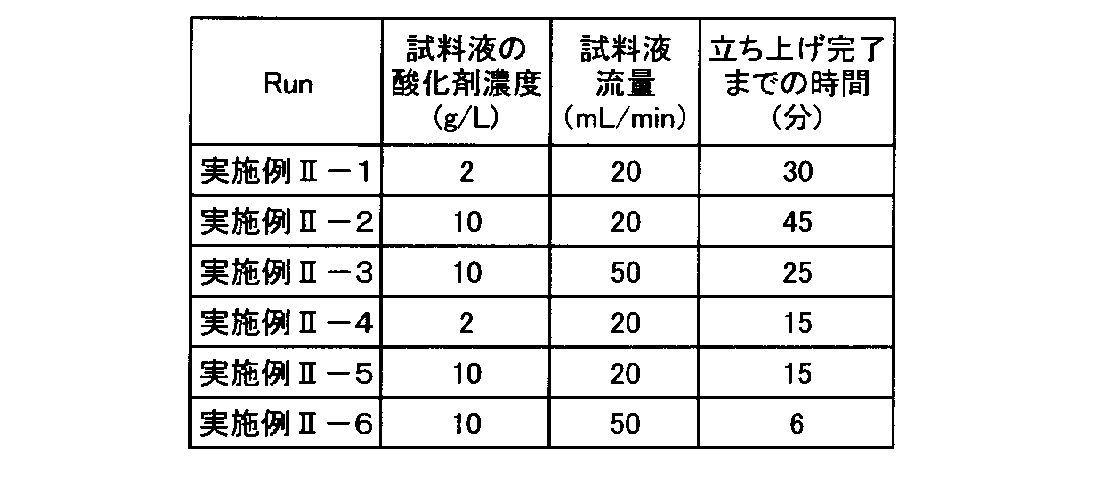
図1に示す酸化剤濃度の測定装置と図6に示す酸化剤濃度の測定装置を用い、実施例I-1,2と同様にして酸化剤濃度の測定を行う際の立ち上げ時間を比較する実験を行った。
図1の酸化剤濃度の測定装置を用いて測定を行った。
ESAユニットから、試料液として過硫酸溶液(92重量%硫酸溶液を電解;酸化剤濃度の設計値2g/L(as H2S2O8))を流量20mL/minで容量100mLの加熱分解器1に滞留時間5分で通液して、試料液を200℃まで昇温し、酸化剤を分解して酸素ガス濃度から酸化剤濃度を算出したところ2g/Lであることを確認した。
加熱分解器1の加熱を停止し、ESAユニットからの過硫酸溶液の供給を止め、計測を一時停止した。
ESAユニットからの送液を再開し、加熱分解器1に試料液が満たされてから200℃加熱を再開した。
送液再開から酸素ガス流量が安定し、立ち上げが完了するまでに要した時間は30分であった。
図1の酸化剤濃度の測定装置を用いて測定を行った。
ESAユニットから、試料液として過硫酸溶液(92重量%硫酸溶液を電解;酸化剤濃度の設計値10g/L(as H2S2O8))を流量20mL/minで容量100mLの加熱分解器1に滞留時間5分で通液して、試料液を200℃まで昇温し、酸化剤を分解して酸素ガス濃度から酸化剤濃度を算出したところ10g/Lであることを確認した。
加熱分解器1の加熱を停止し、ESAユニットからの過硫酸溶液の供給を止め、計測を一時停止した。
ESAユニットからの送液を再開し、加熱分解器1に試料液が満たされてから200℃加熱を再開した。
送液再開から酸素ガス流量が安定し、立ち上げが完了するまでに要した時間は45分であった。
図1の酸化剤濃度の測定装置を用いて測定を行った。
ESAユニットから、試料液として過硫酸溶液(92重量%硫酸溶液を電解;酸化剤濃度の設計値10g/L(as H2S2O8))を流量50mL/minで容量100mLの加熱分解器1に滞留時間5分で通液して、試料液を200℃まで昇温し、酸化剤を分解して酸素ガス濃度から酸化剤濃度を算出したところ10g/Lであることを確認した。
加熱分解器1の加熱を停止し、ESAユニットからの過硫酸溶液の供給を止め、計測を一時停止した。
ESAユニットからの送液を再開し、加熱分解器1に試料液が満たされてから200℃加熱を再開した。
送液再開から酸素ガス流量が安定し、立ち上げが完了するまでに要した時間は25分であった。
図6の酸化剤濃度の測定装置を用いて測定を行った。
ESAユニットから、試料液として過硫酸溶液(92重量%硫酸溶液を電解;酸化剤濃度の設計値2g/L(as H2S2O8))を流量20mL/minで容量100mLの加熱分解器1に滞留時間5分で通液して、試料液を200℃まで昇温し、酸化剤を分解して酸素ガス濃度から酸化剤濃度を算出したところ2g/Lであることを確認した。
ESAユニットからの過硫酸溶液供給を停止すると同時に、代替液タンク8から代替液(酸化剤濃度2g/L(as H2S2O8)の過硫酸溶液)を20mL/minで供給した。その際、加熱分解器1の加熱を継続して200℃を保持した。
ESAユニットからの試料液の送液を再開し、代替液タンク8からの送液を停止した。加熱分解器1は200℃を保持したままであり、送液再開から酸素ガス流量が安定し、立ち上げが完了するまでに要した時間は15分であった。
図6の酸化剤濃度の測定装置を用いて測定を行った。
ESAユニットから、試料液として過硫酸溶液(92重量%硫酸溶液を電解;酸化剤濃度の設計値10g/L(as H2S2O8))を流量20mL/minで容量100mLの加熱分解器1に滞留時間5分で通液して、試料液を200℃まで昇温し、酸化剤を分解して酸素ガス濃度から酸化剤濃度を算出したところ10g/Lであることを確認した。
ESAユニットからの過硫酸溶液供給を停止すると同時に、代替液タンク8から代替液(酸化剤濃度10g/L(as H2S2O8)の過硫酸溶液)を20mL/minで供給した。その際、加熱分解器1の加熱を継続して200℃を保持した。
ESAユニットからの試料液の送液を再開し、代替液タンク8からの送液を停止した。加熱分解器1は200℃を保持したままであり、送液再開から酸素ガス流量が安定し、立ち上げが完了するまでに要した時間は15分であった。
図6の酸化剤濃度の測定装置を用いて測定を行った。
ESAユニットから、試料液として過硫酸溶液(92重量%硫酸溶液を電解;酸化剤濃度の設計値10g/L(as H2S2O8))を流量50mL/minで容量100mLの加熱分解器1に滞留時間5分で通液して、試料液を200℃まで昇温し、酸化剤を分解して酸素ガス濃度から酸化剤濃度を算出したところ10g/Lであることを確認した。
ESAユニットからの過硫酸溶液供給を停止すると同時に、代替液タンク8から代替液(酸化剤濃度10g/L(as H2S2O8)の過硫酸溶液)を50mL/minで供給した。その際、加熱分解器1の加熱を継続して200℃を保持した。
ESAユニットからの試料液の送液を再開し、代替液タンク8からの送液を停止した。加熱分解器1は200℃を保持したままであり、送液再開から酸素ガス流量が安定し、立ち上げが完了するまでに要した時間は6分であった。
本出願は、2015年1月14日付で出願された日本特許出願2015-005079及び2016年1月6日付で出願された日本特許出願2016-000821に基づいており、その全体が引用により援用される。
2 気液分離器
3 分離液冷却器
4 分離液返送タンク
5 ガス冷却器
6 演算器
7 デミスター
8 代替液タンク
11F 液流量計
17F ガス流量計
20 貯留槽
22 洗浄機
28 酸化剤濃度測定ユニット
30 枚葉洗浄装置
31,32 貯留槽
33 電解装置
44 予備加熱器
46 加熱器
60 酸化剤濃度モニタリング装置
70 貯留槽
73 電解セル
75 気液分離器
80 酸化剤濃度測定ユニット
Claims (28)
- 電子材料洗浄工程の洗浄液として用いられる試料液の酸化剤濃度を測定する方法であって、
該試料液中の酸化剤の少なくとも一部を分解させ、該酸化剤の分解で発生する酸素ガスを含む放散ガスの放散量を測定し、この測定値に基づいて該試料液の酸化剤濃度を求めることを特徴とする酸化剤濃度の測定方法。 - 請求項1において、前記試料液を、前記酸化剤の分解手段に連続的に導入して該分解手段から酸素ガスを含む放散ガスを流出させる方法であって、該試料液の流量と該放散ガスの流量から該試料液の酸化剤濃度を算出する、酸化剤濃度の測定方法。
- 請求項1又は2において、前記酸化剤の分解方式が、加熱、紫外線、超音波、及び触媒より選ばれる1つ以上である、酸化剤濃度の測定方法。
- 請求項3において、前記試料液が硫酸濃度85重量%以上の酸化剤含有硫酸溶液であり、該酸化剤の分解方式が150℃以上に加熱するものである、酸化剤濃度の測定方法。
- 請求項1ないし4のいずれか1項において、前記試料液中の酸化剤を分解させた後、前記放散ガスを気液分離し、得られた分離ガス量を測定する、酸化剤濃度の測定方法。
- 請求項5において、前記気液分離後、得られた分離ガスを冷却して該ガス中の蒸気およびミストを除去する、酸化剤濃度の測定方法。
- 請求項6において、前記分離ガスを充填材の充填層に通気して蒸気およびミストを除去する、酸化剤濃度の測定方法。
- 請求項1ないし7のいずれか1項において、前記試料液中に、溶解性の有機物、未溶解SS、及び金属イオンのいずれか1種以上が含まれる、酸化剤濃度の測定方法。
- 請求項1ないし8のいずれか1項において、前記電子材料洗浄工程に送液される洗浄液の一部を、該送液系から試料液として分取し、該試料液の酸化剤濃度を測定した後、該送液系の該試料液の分取位置より上流側に戻す、酸化剤濃度の測定方法。
- 請求項1ないし9のいずれか1項において、前記電子材料洗浄工程において、洗浄排液が再生され、前記洗浄液として循環再利用される、酸化剤濃度の測定方法。
- 請求項1ないし10のいずれか1項において、前記試料液を、前記酸化剤の分解手段に連続的に導入して前記酸化剤濃度の測定を行う測定工程と、該酸化剤の分解手段への該試料液の導入を停止する非測定工程とを有し、該非測定工程において、該酸化剤の分解手段に代替液を導入する、酸化剤濃度の測定方法。
- 請求項11において、前記酸化剤の分解手段の分解方式が加熱によるものであり、前記非測定工程においても、該酸化剤の分解手段の加熱を継続する、酸化剤濃度の測定方法。
- 請求項11又は12において、前記代替液の液成分組成と、前記試料液の液成分組成との差が、該試料液の液成分組成に対して±30%以内である、酸化剤濃度の測定方法。
- 電子材料洗浄工程の洗浄液として用いられる試料液の酸化剤濃度を測定する酸化剤濃度の測定装置であって、
該試料液中の酸化剤の少なくとも一部を分解させる酸化剤分解手段と、該酸化剤の分解で発生する酸素ガスを含む放散ガスの放散量を測定する放散ガス量測定手段と、該放散ガス量測定手段の測定値に基づいて該試料液の酸化剤濃度を算出する演算手段とを備えることを特徴とする酸化剤濃度の測定装置。 - 請求項14において、前記試料液を前記酸化剤分解手段に導入する導入配管と、該導入配管に設けられた液流量計と、該酸化剤分解手段で発生した放散ガスを排出する排出配管と、該排出配管に設けられたガス流量計とを有し、前記演算手段は、該液流量計の測定値と該ガス流量計の測定値に基づいて前記酸化剤濃度を算出する、酸化剤濃度の測定装置。
- 請求項14又は15において、前記酸化剤の分解手段の分解方式が、加熱、紫外線、超音波、及び触媒より選ばれる1つ以上である、酸化剤濃度の測定装置。
- 請求項14ないし16のいずれか1項において、前記試料液が硫酸濃度85重量%以上の酸化剤含有硫酸溶液であり、前記酸化剤分解手段の分解方式が150℃以上に加熱するものである、酸化剤濃度の測定装置。
- 請求項14ないし17のいずれか1項において、前記酸化剤分解手段から排出された放散ガスを気液分離する気液分離手段を有し、該気液分離手段で分離された分離ガスが前記放散ガス量測定手段に送給される、酸化剤濃度の測定装置。
- 請求項18において、前記気液分離手段で分離させた分離ガスを冷却して該ガス中の蒸気およびミストを除去するガス清浄化手段を有し、該ガス清浄化手段で清浄化されたガスが前記放散ガス量測定手段に送給される、酸化剤濃度の測定装置。
- 請求項19において、前記ガス清浄化手段が、充填材の充填層を備える、酸化剤濃度の測定装置。
- 請求項18ないし20のいずれか1項において、前記気液分離手段で分離された分離液の冷却手段を備える、酸化剤濃度の測定装置。
- 請求項14ないし21のいずれか1項において、前記酸化剤分解手段に前記試料液の代りに導入するための代替液を貯留する代替液タンクと、該代替液タンク内の代替液を該酸化剤分解手段に導入する導入配管とを備える、酸化剤濃度の測定装置。
- 請求項22において、前記酸化剤分解手段の分解方式が加熱によるものであり、前記試料液を該酸化剤分解手段に導入する導入配管と、前記代替液タンク内の代替液を該酸化剤分解手段に導入する導入配管とで、液の導入を切り換える切換手段を有し、該酸化剤分解手段への該代替液の導入中も、該酸化剤分解手段の加熱が継続される、酸化剤濃度の測定装置。
- 請求項22又は23において、前記代替液の液成分組成と、前記試料液の液成分組成との差が、該試料液の液成分組成に対して±30%以内である、酸化剤濃度の測定装置。
- 電子材料の洗浄手段と、該洗浄手段に洗浄液を送給する洗浄液送給手段と、該洗浄液送給手段から洗浄液の一部を試料液として分取する試料液分取手段と、該試料液分取手段で分取された試料液の酸化剤濃度を測定する酸化剤濃度測定手段とを備える電子材料洗浄装置であって、該酸化剤濃度測定手段が、請求項14ないし24のいずれか1項に記載の酸化剤濃度の測定装置を備えることを特徴とする電子材料洗浄装置。
- 請求項25において、前記試料液分取手段で分取され、前記酸化剤濃度測定手段で酸化剤濃度が測定された後の試料液を、前記洗浄液送給手段の前記試料液分取位置よりも上流側に返送する試料液返送手段を備える、電子材料洗浄装置。
- 請求項26において、前記酸化剤濃度測定手段が、請求項21に記載の酸化剤濃度の測定装置であり、前記分離液の冷却手段で冷却された液の貯留槽を有し、該貯留槽内の液が、前記試料液返送手段により返送される、電子材料洗浄装置。
- 請求項25ないし27のいずれか1項において、前記洗浄手段で洗浄に使用された洗浄排液を再生する再生手段と、該再生手段で再生された液を洗浄液として前記洗浄手段に循環する循環手段とを備える、電子材料洗浄装置。
Priority Applications (3)
| Application Number | Priority Date | Filing Date | Title |
|---|---|---|---|
| KR1020177010242A KR20170103744A (ko) | 2015-01-14 | 2016-01-06 | 산화제 농도의 측정 방법 및 측정 장치, 그리고 전자 재료 세정 장치 |
| US15/540,807 US20170356891A1 (en) | 2015-01-14 | 2016-01-06 | Method and apparatus for measuring concentration of oxidant and system for cleaning electronic material |
| CN201680002983.XA CN107076716A (zh) | 2015-01-14 | 2016-01-06 | 氧化剂浓度的测定方法及测定装置以及电子材料洗净装置 |
Applications Claiming Priority (4)
| Application Number | Priority Date | Filing Date | Title |
|---|---|---|---|
| JP2015-005079 | 2015-01-14 | ||
| JP2015005079 | 2015-01-14 | ||
| JP2016-000821 | 2016-01-06 | ||
| JP2016000821A JP5979328B2 (ja) | 2015-01-14 | 2016-01-06 | 酸化剤濃度の測定方法および測定装置、並びに電子材料洗浄装置 |
Publications (1)
| Publication Number | Publication Date |
|---|---|
| WO2016114188A1 true WO2016114188A1 (ja) | 2016-07-21 |
Family
ID=56405735
Family Applications (1)
| Application Number | Title | Priority Date | Filing Date |
|---|---|---|---|
| PCT/JP2016/050216 Ceased WO2016114188A1 (ja) | 2015-01-14 | 2016-01-06 | 酸化剤濃度の測定方法および測定装置、並びに電子材料洗浄装置 |
Country Status (1)
| Country | Link |
|---|---|
| WO (1) | WO2016114188A1 (ja) |
Cited By (5)
| Publication number | Priority date | Publication date | Assignee | Title |
|---|---|---|---|---|
| JP2017173218A (ja) * | 2016-03-25 | 2017-09-28 | 栗田工業株式会社 | 酸化剤濃度の測定方法及び測定装置、並びに電子材料洗浄装置 |
| WO2018168014A1 (ja) * | 2017-03-17 | 2018-09-20 | 栗田工業株式会社 | 酸化剤濃度測定装置及び酸化剤濃度測定方法 |
| KR101940663B1 (ko) * | 2017-08-11 | 2019-01-22 | 충남대학교산학협력단 | 촉매 반응부를 가지는 산화제 과잉 시험장치 |
| CN116183812A (zh) * | 2022-12-05 | 2023-05-30 | 上海金艺检测技术有限公司 | 钢铁中氧化亚铁含量的全自动测定方法 |
| WO2024161748A1 (ja) * | 2023-01-31 | 2024-08-08 | 株式会社Screenホールディングス | 基板処理装置、および、基板処理方法 |
Citations (7)
| Publication number | Priority date | Publication date | Assignee | Title |
|---|---|---|---|---|
| JPH02110367A (ja) * | 1988-10-20 | 1990-04-23 | Tokico Ltd | 炭素量測定装置 |
| JPH07928Y2 (ja) * | 1988-11-04 | 1995-01-11 | 株式会社島津製作所 | 水素化物発生装置 |
| JPH0755789A (ja) * | 1993-08-20 | 1995-03-03 | Tokico Ltd | 液管理装置 |
| JPH1151931A (ja) * | 1997-07-30 | 1999-02-26 | Shimadzu Corp | 水質連続分析計 |
| JP2012189320A (ja) * | 2011-02-23 | 2012-10-04 | Kurita Water Ind Ltd | 過硫酸濃度の測定方法、過硫酸濃度測定装置、及び過硫酸供給装置 |
| JP2013253888A (ja) * | 2012-06-07 | 2013-12-19 | Hitachi High-Technologies Corp | 質量分析を用いた定量分析方法と定量分析装置 |
| WO2015012041A1 (ja) * | 2013-07-23 | 2015-01-29 | 栗田工業株式会社 | 全酸化性物質濃度の測定方法、基板洗浄方法および基板洗浄システム |
-
2016
- 2016-01-06 WO PCT/JP2016/050216 patent/WO2016114188A1/ja not_active Ceased
Patent Citations (7)
| Publication number | Priority date | Publication date | Assignee | Title |
|---|---|---|---|---|
| JPH02110367A (ja) * | 1988-10-20 | 1990-04-23 | Tokico Ltd | 炭素量測定装置 |
| JPH07928Y2 (ja) * | 1988-11-04 | 1995-01-11 | 株式会社島津製作所 | 水素化物発生装置 |
| JPH0755789A (ja) * | 1993-08-20 | 1995-03-03 | Tokico Ltd | 液管理装置 |
| JPH1151931A (ja) * | 1997-07-30 | 1999-02-26 | Shimadzu Corp | 水質連続分析計 |
| JP2012189320A (ja) * | 2011-02-23 | 2012-10-04 | Kurita Water Ind Ltd | 過硫酸濃度の測定方法、過硫酸濃度測定装置、及び過硫酸供給装置 |
| JP2013253888A (ja) * | 2012-06-07 | 2013-12-19 | Hitachi High-Technologies Corp | 質量分析を用いた定量分析方法と定量分析装置 |
| WO2015012041A1 (ja) * | 2013-07-23 | 2015-01-29 | 栗田工業株式会社 | 全酸化性物質濃度の測定方法、基板洗浄方法および基板洗浄システム |
Cited By (7)
| Publication number | Priority date | Publication date | Assignee | Title |
|---|---|---|---|---|
| JP2017173218A (ja) * | 2016-03-25 | 2017-09-28 | 栗田工業株式会社 | 酸化剤濃度の測定方法及び測定装置、並びに電子材料洗浄装置 |
| WO2017163456A1 (ja) * | 2016-03-25 | 2017-09-28 | 栗田工業株式会社 | 酸化剤濃度の測定方法及び測定装置、並びに電子材料洗浄装置 |
| WO2018168014A1 (ja) * | 2017-03-17 | 2018-09-20 | 栗田工業株式会社 | 酸化剤濃度測定装置及び酸化剤濃度測定方法 |
| JP2018155581A (ja) * | 2017-03-17 | 2018-10-04 | 栗田工業株式会社 | 酸化剤濃度測定装置及び酸化剤濃度測定方法 |
| KR101940663B1 (ko) * | 2017-08-11 | 2019-01-22 | 충남대학교산학협력단 | 촉매 반응부를 가지는 산화제 과잉 시험장치 |
| CN116183812A (zh) * | 2022-12-05 | 2023-05-30 | 上海金艺检测技术有限公司 | 钢铁中氧化亚铁含量的全自动测定方法 |
| WO2024161748A1 (ja) * | 2023-01-31 | 2024-08-08 | 株式会社Screenホールディングス | 基板処理装置、および、基板処理方法 |
Similar Documents
| Publication | Publication Date | Title |
|---|---|---|
| JP6024936B2 (ja) | 全酸化性物質濃度の測定方法、基板洗浄方法および基板洗浄システム | |
| WO2016114188A1 (ja) | 酸化剤濃度の測定方法および測定装置、並びに電子材料洗浄装置 | |
| CN102007579B (zh) | 电子材料用清洗水、电子材料的清洗方法及溶气水的供给系统 | |
| JP2009219995A (ja) | ガス溶解水供給システム | |
| JPS63153825A (ja) | 硫酸液の純粋化方法及び装置 | |
| TWI331775B (en) | Equipment and method for measuring silicon concentration in phosphoric acid solution | |
| JP6430772B2 (ja) | 炭酸ガス溶解水供給システム、炭酸ガス溶解水供給方法、およびイオン交換装置 | |
| JP5773132B2 (ja) | 過硫酸濃度の測定方法、過硫酸濃度測定装置、及び過硫酸供給装置 | |
| EP2733724B1 (en) | Method for cleaning metal gate semiconductor | |
| JP5979328B2 (ja) | 酸化剤濃度の測定方法および測定装置、並びに電子材料洗浄装置 | |
| US20150068985A1 (en) | Method and Apparatus for Removing Chloride from Samples Containing Volatile Organic Carbon | |
| JP6427378B2 (ja) | アンモニア溶解水供給システム、アンモニア溶解水供給方法、およびイオン交換装置 | |
| JP3914722B2 (ja) | 水系レジスト剥離液管理装置及び水系レジスト剥離液管理方法 | |
| JP5859287B2 (ja) | 超純水中の微量過酸化水素の濃度測定方法 | |
| JP5499602B2 (ja) | 有効酸化性物質の濃度測定方法 | |
| JP6265289B1 (ja) | 酸化剤濃度測定装置及び酸化剤濃度測定方法 | |
| TW201615557A (zh) | 含有氨之排放水的處理方法及處理裝置 | |
| JP6168184B1 (ja) | 酸化剤濃度の測定方法及び測定装置、並びに電子材料洗浄装置 | |
| JP2018182098A (ja) | 洗浄水供給装置 | |
| KR20030001335A (ko) | 비수계 내식막 박리액 관리장치 및 비수계 내식막 박리액관리방법 | |
| JP2017109148A (ja) | アンモニウムイオンを含有する廃液の廃液処理装置、廃液処理装置の制御方法及び廃液処理方法 |
Legal Events
| Date | Code | Title | Description |
|---|---|---|---|
| 121 | Ep: the epo has been informed by wipo that ep was designated in this application |
Ref document number: 16737259 Country of ref document: EP Kind code of ref document: A1 |
|
| ENP | Entry into the national phase |
Ref document number: 20177010242 Country of ref document: KR Kind code of ref document: A |
|
| WWE | Wipo information: entry into national phase |
Ref document number: 15540807 Country of ref document: US |
|
| NENP | Non-entry into the national phase |
Ref country code: DE |
|
| 122 | Ep: pct application non-entry in european phase |
Ref document number: 16737259 Country of ref document: EP Kind code of ref document: A1 |