WO2016113815A1 - 車載機 - Google Patents
車載機 Download PDFInfo
- Publication number
- WO2016113815A1 WO2016113815A1 PCT/JP2015/006368 JP2015006368W WO2016113815A1 WO 2016113815 A1 WO2016113815 A1 WO 2016113815A1 JP 2015006368 W JP2015006368 W JP 2015006368W WO 2016113815 A1 WO2016113815 A1 WO 2016113815A1
- Authority
- WO
- WIPO (PCT)
- Prior art keywords
- vehicle
- positioning
- reference value
- abnormality
- positioning performance
- Prior art date
- Legal status (The legal status is an assumption and is not a legal conclusion. Google has not performed a legal analysis and makes no representation as to the accuracy of the status listed.)
- Ceased
Links
Images



Classifications
-
- G—PHYSICS
- G01—MEASURING; TESTING
- G01C—MEASURING DISTANCES, LEVELS OR BEARINGS; SURVEYING; NAVIGATION; GYROSCOPIC INSTRUMENTS; PHOTOGRAMMETRY OR VIDEOGRAMMETRY
- G01C21/00—Navigation; Navigational instruments not provided for in groups G01C1/00 - G01C19/00
- G01C21/26—Navigation; Navigational instruments not provided for in groups G01C1/00 - G01C19/00 specially adapted for navigation in a road network
-
- G—PHYSICS
- G01—MEASURING; TESTING
- G01S—RADIO DIRECTION-FINDING; RADIO NAVIGATION; DETERMINING DISTANCE OR VELOCITY BY USE OF RADIO WAVES; LOCATING OR PRESENCE-DETECTING BY USE OF THE REFLECTION OR RERADIATION OF RADIO WAVES; ANALOGOUS ARRANGEMENTS USING OTHER WAVES
- G01S19/00—Satellite radio beacon positioning systems; Determining position, velocity or attitude using signals transmitted by such systems
- G01S19/01—Satellite radio beacon positioning systems transmitting time-stamped messages, e.g. GPS [Global Positioning System], GLONASS [Global Orbiting Navigation Satellite System] or GALILEO
- G01S19/13—Receivers
- G01S19/23—Testing, monitoring, correcting or calibrating of receiver elements
Definitions
- This disclosure relates to an in-vehicle unit that performs wireless communication.
- Patent Literature 1 discloses a technique for detecting an abnormality occurring in an in-vehicle device by an impact sensor provided in the in-vehicle device and notifying the center.
- an in-vehicle device transmits information including the position of a mounted vehicle (also referred to as a host vehicle) measured by a positioning device using a satellite positioning system to an in-vehicle device or a roadside device of another vehicle.
- a system that enables a host vehicle driver to receive a service (hereinafter referred to as an in-vehicle communication service) according to the position of the host vehicle.
- the positioning accuracy should decrease, but it is difficult to determine whether the decrease in positioning accuracy is due to an abnormality in the positioning device or due to environmental factors. Therefore, it can be said that it is difficult to detect an abnormality of a positioning device using a satellite positioning system.
- An object of the present disclosure is to provide an in-vehicle device that accurately detects an abnormality of a positioning device using a satellite positioning system.
- the in-vehicle device is used in each of a plurality of host vehicles including a target vehicle and a plurality of surrounding vehicles around the target vehicle, and a current position of each host vehicle is determined using a satellite positioning system.
- a vehicle-to-vehicle communication device that transmits and receives information through vehicle-to-vehicle communication.
- the in-vehicle device used in the target vehicle receives, via the inter-vehicle communication device, another device positioning performance index that is an index indicating the positioning performance of the positioning device that measures the current position of each of the plurality of surrounding vehicles.
- a reference value setting unit and a separate machine abnormality detection unit are examples of a reference value setting unit and a separate machine abnormality detection unit.
- the reference value setting unit sequentially sets the reference value of the positioning performance index from the received separate device positioning performance index.
- the separate machine abnormality detection unit compares the set reference value with the separate machine positioning performance index for the positioning machine of the target peripheral vehicle that is the predetermined diagnosis target among the plurality of peripheral vehicles, thereby Detects a positioning device abnormality.
- the reference value serving as a reference for the positioning performance index is sequentially set by the reference value setting unit from the positioning performance index received from the plurality of surrounding vehicles by the inter-vehicle communication device, the in-vehicle device and the vehicle of the target vehicle are set.
- a reference value serving as a reference for a positioning performance index can be set each time from a set of positioning performance indices received from neighboring vehicles located in the vicinity so that inter-vehicle communication is possible.
- the positioning performance index is an index representing the positioning performance of a positioning device that measures the current position of the vehicle using a satellite positioning system. Therefore, the reference value setting unit can set a reference value that serves as a reference for the positioning performance index of the positioning device in an area narrowed down in the vicinity of the target vehicle.
- the reference value is a value serving as a reference for positioning performance set from a set of positioning performance indicators. Therefore, if there is a drop in positioning performance that is not limited to some surrounding vehicles, such as when the positioning performance is reduced due to environmental factors in an area narrowed down in the vicinity of the target vehicle, this positioning performance The reference value also fluctuates with the decrease. On the other hand, since the influence on the reference value is mitigated with respect to a decrease in positioning performance limited to some peripheral vehicles due to an abnormality of the positioning device, fluctuations in the reference value can be suppressed.
- the reference value set by the reference value setting unit is compared with the positioning performance index of the positioning device of the surrounding vehicle received from the surrounding vehicle by the inter-vehicle communication device. Since the abnormality of the positioning device is detected, it is possible to accurately detect the abnormality of the positioning device of the surrounding vehicle.
- the in-vehicle device is used in each of a plurality of host vehicles including the target vehicle and at least one surrounding vehicle around the target vehicle, and each host vehicle using a satellite positioning system.
- the present invention is provided with a positioning device that measures the current position of the vehicle and a vehicle-to-vehicle communication device that transmits and receives information through vehicle-to-vehicle communication.
- the in-vehicle device used in the target vehicle is a separate device positioning that is an index indicating the positioning performance of the positioning device used in each of at least one surrounding vehicle transmitted by inter-vehicle communication via the inter-vehicle communication device.
- a performance index is received, and further includes a reference value setting unit, a positioning performance index acquisition unit, and an own device abnormality detection unit.
- the reference value setting unit sequentially sets the reference value of the positioning performance index from the separate device positioning performance index.
- the positioning performance index acquisition unit acquires the own positioning performance index for the positioning machine of the target vehicle.
- the own device abnormality detection unit compares the reference value set by the reference value setting unit with the own device positioning performance index of the target vehicle positioning device acquired by the positioning performance index acquisition unit, thereby determining the positioning device of the target vehicle. Detect abnormalities.
- the reference value serving as a reference for the positioning performance index is sequentially set by the reference value setting unit from the positioning performance index received from the plurality of surrounding vehicles by the inter-vehicle communication device, the in-vehicle device and the vehicle of the target vehicle are set.
- a reference value serving as a reference for a positioning performance index can be set each time from a set of positioning performance indices received from neighboring vehicles located in the vicinity so that inter-vehicle communication is possible.
- the positioning performance index is an index representing the positioning performance of a positioning device that measures the current position of the vehicle using a satellite positioning system. Therefore, the reference value setting unit can set a reference value that serves as a reference for the positioning performance index of the positioning device in an area narrowed down in the vicinity of the target vehicle.
- the reference value is a value serving as a reference for positioning performance set from a set of positioning performance indicators. Therefore, if there is a drop in positioning performance that is not limited to some vehicles, such as a temporary drop in positioning performance due to environmental factors in an area narrowed down in the vicinity of the target vehicle, this positioning The reference value also fluctuates as performance decreases. On the other hand, since the influence on the reference value is mitigated with respect to a decrease in positioning performance limited to some vehicles due to an abnormality in the positioning device, fluctuations in the reference value can be suppressed.
- the own aircraft abnormality detection unit compares the reference value set by the reference value setting unit with the positioning performance index for the positioning device of the target vehicle acquired from the target vehicle by the positioning performance index acquisition unit. Since the abnormality of the machine is detected, it is possible to accurately detect the abnormality of the positioning machine of the target vehicle.
- FIG. 1 shows an example of the schematic structure of a communication system
- a flowchart showing an example of reference value setting related processing in the controller of the target vehicle The flowchart which shows an example of another machine abnormality detection related processing in the controller of the target vehicle, It is a flowchart which shows an example of the own apparatus abnormality detection related process in the controller of an object vehicle.
- FIG. 1 is a diagram illustrating an example of a schematic configuration of a communication system 100 to which the present disclosure is applied.
- the communication system 100 shown in FIG. 1 includes an in-vehicle device 1b used in the vehicle B, an in-vehicle device 1a used in each of the vehicles A around the vehicle B, a provider terminal 2 as a roadside device installed on the roadside, Center 3 is included.
- the vehicle B is also referred to as the target vehicle B or the first vehicle.
- the vehicle A is also referred to as a peripheral vehicle A, a second vehicle, or another vehicle.
- the vehicle carrying the vehicle-mounted device is also referred to as a host vehicle, and both the vehicle A and the vehicle B correspond to this.
- the in-vehicle device 1b is also referred to as a first in-vehicle device.
- the vehicle-mounted device 1a is also referred to as a peripheral vehicle-mounted device, another vehicle-mounted device, or a second vehicle-mounted device.
- the communication system 100 includes a configuration including three in-vehicle devices 1 a used in each of three peripheral vehicles.
- the configuration is not limited thereto, and a plurality of in-vehicle devices 1 a other than three are included.
- a configuration may be used.
- the in-vehicle device 1a and the in-vehicle device 1b perform transmission / reception of information by wireless communication not via a communication network. That is, vehicle-to-vehicle communication is performed. Note that information is used not only as not countable but also countable.
- the communication range of the inter-vehicle communication may be, for example, a radius of about several tens of meters to several hundreds of meters.
- the in-vehicle device 1b and the provider terminal 2 transmit / receive information by wireless communication not via the communication network. That is, road-to-vehicle communication is performed.
- the inter-vehicle communication and the road-to-vehicle communication may be configured to use the same frequency band or may be configured to use different frequency bands.
- different frequencies in the same frequency band may be used, and communication may be performed while shifting the period.
- Examples of frequency bands used for vehicle-to-vehicle communication and road-to-vehicle communication include a 5.9 GHz band, a 5.8 GHz band, and a 700 MHz band.
- the in-vehicle device 1b and the center 3 perform wide area communication via a communication network.
- communication is performed via a communication network such as a mobile phone network or the Internet.
- the in-vehicle device 1a and the in-vehicle device 1b may be configured to be incorporated (that is, mounted) in the vehicle, or may be simply brought into the vehicle and detachably attached to a holder or the like. The details of the in-vehicle device 1a and the in-vehicle device 1b will be described later.
- the provider terminal 2 exchanges information related to the provision of services by road-to-vehicle communication with the in-vehicle device 1b used in the vehicle located in the wireless communication area of the own terminal.
- Examples of services include automatic payment through drive-through, automatic payment of parking fees at toll parking lots, support for traffic at intersections, and provision of traffic information. What is necessary is just to set so that the radio
- the center 3 is a server device, for example, and receives a notification transmitted from the in-vehicle device 1b by wide area communication.
- the center 3 may be composed of one server device or may be composed of a plurality of server devices.
- the vehicle-mounted device 1a includes a controller 11a, a position detector 12a, and a narrow area communication device (also referred to as an inter-vehicle communication device) 13a.
- the position detector 12a includes a GNSS receiver used in GNSS (Global Navigation Satellite System), and sequentially detects the current position of the surrounding vehicle A based on a signal received by an antenna from a positioning satellite (that is, positioning). )
- GNSS Global Navigation Satellite System
- This GNSS is also referred to as a satellite positioning system, and the position detector 12a is also referred to as a positioning machine.
- the measured current position (hereinafter referred to as vehicle position) is represented by, for example, latitude / longitude.
- the position detector 12a is configured to perform dead reckoning that complements the positioning result using dead reckoning navigation that estimates the vehicle position based on the pulse signal output from the wheel speed sensor, the yaw rate detected by the gyro sensor, and the like. It is good.
- the position detector 12a outputs information on positioning performance using GNSS to the controller 11a.
- Examples of information on positioning performance using GNSS include reception sensitivity such as the C / N ratio of satellites used for positioning, the number of visible satellites in the field of view at the time of positioning (hereinafter, the number of satellites), the last positioning time, There are positioning errors.
- DOP Deution of Precision
- GNSS GNSS
- the narrow area communication device 13a performs vehicle-to-vehicle communication with the vehicle-mounted device 1b located within the communication range via an antenna for transmission and reception. More specifically, the narrow area communication device 13a transmits a signal in accordance with an instruction from the controller 11a.
- the controller 11a is also referred to as an electronic control unit or a control circuit.
- a CPU a memory such as a ROM or a RAM, an I / O, and a bus for connecting them are executed, and various processes are executed by executing a control program stored in the ROM. Details of the controller 11a will be described later. Note that some or all of the functions executed by the controller 11a may be configured by hardware using one or a plurality of ICs.
- the controller 11a includes a positioning performance index acquisition unit 111a and a transmission processing unit 112a.
- the positioning performance index acquisition unit 111a acquires information related to positioning performance using GNSS (hereinafter referred to as positioning performance index) output from the position detector 12a.
- the positioning performance index is the above-described reception sensitivity, number of satellites, final positioning time, positioning error, etc., and any of these may be obtained, or a set of all or a part of these may be obtained. It is good also as a structure.
- the transmission processing unit 112a transmits the positioning performance index for the position detector 12a acquired by the positioning performance index acquisition unit 111a from the narrow area communication device 13a by inter-vehicle communication.
- the timing for transmitting the positioning performance index may be a predetermined cycle such as every 100 msec, or may be when a predetermined trigger is detected.
- the predetermined trigger when the in-vehicle device 1a is configured to perform road-to-vehicle communication with the roadside device, there is a start time of road-to-vehicle communication.
- an identifier such as a device ID for identifying the in-vehicle device 1a that is the transmission source may be assigned and transmitted.
- the in-vehicle device 1b includes a controller 11b, a position detector 12b, a narrow area communication device (also referred to as a vehicle / road vehicle communication device) 13b, and a wide area communication device 14b.
- the position detector 12b has a different member number for convenience, but is the same as the position detector 12a described above. That is, the current position of the target vehicle B using the in-vehicle device 1b is measured using the satellite positioning system. Therefore, this position detector 12b is also referred to as a positioning machine.
- the narrow area communication device 13b performs vehicle-to-vehicle communication with the vehicle-mounted device 1a located within the communication range, or performs road-to-vehicle communication with the provider terminal 2 via the transmission / reception antenna. More specifically, the narrow area communication device 13b transmits a signal in accordance with an instruction from the controller 11b. This narrow area communication device 13b is also referred to as an inter-vehicle communication device.
- the wide area communication device 14b communicates with the center 3 via a communication network such as a mobile phone network or the Internet.
- the controller 11b is also referred to as an electronic control unit or a control circuit.
- a CPU a memory such as a ROM or a RAM, an I / O, and a bus for connecting them are executed, and various processes are executed by executing a control program stored in the ROM. Details of the controller 11b will be described later. Note that some or all of the functions executed by the controller 11b may be configured in hardware by one or a plurality of ICs.
- the controller 11b includes a positioning position acquisition unit 111b, a positioning performance index acquisition unit 112b, a transmission processing unit 113b, a peripheral index acquisition unit 114b, an index storage unit 115b, a reference value setting unit 116b, and a separate device abnormality detection.
- the positioning position acquisition unit 111b sequentially acquires the vehicle position measured by the position detector 12b.
- the positioning performance index acquisition unit 112b acquires the positioning performance index output from the position detector 12b in the same manner as the positioning performance index acquisition unit 111a.
- the transmission processing unit 113b transmits the vehicle position acquired by the positioning position acquisition unit 111b from the narrow area communication device 13b by road-to-vehicle communication.
- the timing at which the vehicle position is transmitted by road-to-vehicle communication may be at the time of receiving a signal transmitted from the provider terminal 2 by road-to-vehicle communication.
- the in-vehicle device 1b receives a service corresponding to the vehicle position from the provider terminal 2.
- the positioning performance index for the position detector 12a of the peripheral vehicle A transmitted from the in-vehicle device 1a (that is, the peripheral vehicle A) by inter-vehicle communication is transmitted via the narrow area communication device 13b. Acquire sequentially. And the acquired positioning performance parameter
- the peripheral index acquisition unit 114b stores the received positioning performance index in the index storage unit 115b every time the positioning performance index is received from a different peripheral vehicle A by the narrow area communication device 13b. Thereby, when the positioning performance index is received from the plurality of surrounding vehicles A, the positioning performance index for the position detectors 12a of the plurality of surrounding vehicles A is accumulated in the index storage 115b.
- the positioning performance index received from different surrounding vehicles A is individually recognized by storing the positioning performance index in association with the identifier for identifying the in-vehicle device 1a as the transmission source. You can do it.
- the peripheral index acquisition unit 114b receives the positioning performance index from the in-vehicle device 1a that has already stored the positioning performance index in the index storage unit 115b, the positioning index that has been stored with the newly received positioning performance index. Should be updated.
- the positioning performance index that has not been updated for a certain period of time, such as several seconds, is deleted from the index storage unit 115b, the positioning performance index stored in the index storage unit 115b becomes the inter-vehicle communication of the in-vehicle device 1b. What is necessary is just to make it narrow down to the positioning performance parameter
- the reference value setting unit 116b sequentially sets a reference value serving as a reference for the set of positioning performance indices from the set of positioning performance indices received from the plurality of surrounding vehicles A stored in the index storage unit 115b.
- a mode value of a set of positioning performance indexes may be calculated, and the calculated mode value may be used as a reference value.
- an average value of a set of positioning performance indices may be used as a reference value, and an intermediate value of a set of positioning performance indices may be used as a reference value.
- the reference value setting unit 116b sets a reference value for each type when there are multiple types of positioning performance indicators. For example, when the type of positioning performance index is reception sensitivity, a reference value for reception sensitivity is set. The same applies to the number of satellites, final positioning time, and positioning error.
- the reference value setting unit 116b may set a reference value at regular intervals.
- the fixed period here is a time interval longer than a period of time estimated to cause a change in the set of positioning performance indexes stored in the index storage device 115b, and can be arbitrarily set as a time interval. To do.
- the reference value setting unit 116b may be configured to set the reference value every time a new positioning performance index is stored in the index storage unit 115b.
- the set of positioning performance indexes stored in the index storage device 115b is a set of positioning performance indexes received from the surrounding vehicle A actually located around the target vehicle B at that time. Therefore, the reference value setting unit 116b sets a reference value of a set of positioning performance indices received from the surrounding vehicle A actually located around the target vehicle B each time.
- the separate machine abnormality detection unit 117b compares the reference value set most recently by the reference value setting unit 116b with the positioning performance index for the position detector 12a of the surrounding vehicle A acquired by the peripheral index acquisition unit 114b.
- an abnormality of the position detector 12a is detected.
- an abnormality of the in-vehicle device 1a provided with the position detector 12a is detected.
- no abnormality is detected.
- the own aircraft abnormality detection unit 118b compares the reference value set most recently by the reference value setting unit 116b with the positioning performance index for the position detector 12b of the target vehicle B acquired by the positioning performance index acquisition unit 112b. When the positioning performance index for the position detector 12b deviates from the reference value by the predetermined value or more, an abnormality of the position detector 12b is detected. Further, when the deviation from the reference value is less than a predetermined value, no abnormality is detected.
- the different machine abnormality detection unit 117b and the own machine abnormality detection unit 118b have the same objects to be compared. Specifically, when the type of positioning performance index is reception sensitivity, it is compared with a reference value for reception sensitivity. The same applies to the number of satellites, final positioning time, and positioning error.
- the abnormality notification processing unit 119b indicates that the abnormality in the position detector 12a of the surrounding vehicle A has been detected.
- the abnormality notification processing unit 119b detects that the abnormality of the position detector 12b of the target vehicle B is detected when the own device abnormality detection unit 118b detects the abnormality of the position detector 12b of the target vehicle B.
- 14b is sent to the center 3 by wide area communication.
- the center 3 that has received the notification indicating that an abnormality has been detected, for example, an operator or the like deals with the abnormality.
- the position detector 12a and the position detector 12b are not limited to detecting and notifying the abnormality but the position detector 12a and the position detector 12b are detected when an abnormality is detected in the position detector 12a and the position detector 12b. It is good also as a structure which detects abnormality of the vehicle equipment 1a and vehicle equipment 1b provided with 12b, and notifies abnormality of the vehicle equipment 1a or vehicle equipment 1b.
- the described flowchart includes a plurality of sections (or referred to as steps), and each section is expressed as, for example, S1. Further, each section can be divided into a plurality of subsections, while a plurality of sections can be combined into one section. Each section can be referred to as a device, module, unit, or unique name (eg, a detector).
- the section includes (i) not only a section of software combined with a hardware unit (eg, a computer) but also (ii) a section of hardware (eg, an integrated circuit, a wiring logic circuit) and related devices. It can be realized with or without the function.
- the hardware section can be included inside the microcomputer.
- the flowchart of FIG. 4 may be configured to start when the ignition power of the target vehicle B is turned on.
- the surrounding index acquisition unit 114b acquires the positioning performance index for the position detector 12a of the surrounding vehicle A transmitted from the surrounding vehicle A through the inter-vehicle communication via the narrow area communication device 13b.
- the process proceeds to S2.
- the peripheral index acquisition unit 114b stores the acquired positioning performance index in the index storage unit 115b.
- the predetermined plural is a value determined in consideration of the reliability required for the reference value set by the reference value setting unit 116b from the set of positioning performance indexes stored in the index storage unit 115b.
- the reference value setting unit 116b sets a reference value serving as a reference for the set of positioning performance indicators from the set of positioning performance indicators received from the plurality of surrounding vehicles A stored in the indicator storage device 115b. To do.
- the separate machine abnormality detection related process is a process related to the detection of an abnormality in the position detector 12a of the surrounding vehicle A.
- the flowchart of FIG. 5 may be configured to start when the ignition power of the target vehicle B is turned on.
- the surrounding index acquisition unit 114b acquires the positioning performance index for the position detector 12a of the surrounding vehicle A transmitted from the surrounding vehicle A by inter-vehicle communication via the narrow area communication device 13b. In the case (YES in S21), the process proceeds to S22. On the other hand, if it has not been acquired (NO in S21), the process proceeds to S26.
- the separate apparatus abnormality detection unit 117b detects the latest reference value set in the reference value setting related process and the position detector of the surrounding vehicle A (also referred to as target surrounding vehicle) as the diagnostic target acquired in S21.
- the positioning performance index for 12a is compared.
- the abnormality notification processing unit 119b notifies the center 3 from the wide area communication device 14b to the center 3 that the abnormality of the position detector 12a has been detected for the surrounding vehicle A that acquired the positioning performance index in S21.
- the own machine abnormality detection related process is a process related to the detection of an abnormality in the position detector 12b of the target vehicle B.
- the flowchart of FIG. 6 may be configured to start when the ignition power of the target vehicle B is turned on.
- the positioning performance index acquisition unit 112b acquires the positioning performance index output from the position detector 12b.
- the process proceeds to S43.
- the process proceeds to S46.
- the own aircraft abnormality detection unit 118b compares the latest reference value set in the reference value setting related process with the positioning performance index for the position detector 12b of the target vehicle B acquired in S41.
- the abnormality notification processing unit 119b notifies the center 3 from the wide area communication device 14b to the center 3 that the abnormality has been detected in the position detector 12b of the target vehicle B.
- the reference value set by the reference value setting unit 116b is a set of positioning performance indexes received from the surrounding vehicle A located in the vicinity so that the vehicle can communicate with the target vehicle B at that time. This is the standard value. Therefore, when the positioning performance is not limited to some of the surrounding vehicles A and the target vehicle B, such as when the positioning performance is reduced due to environmental factors in an area narrowed down in the vicinity of the target vehicle B.
- the reference value also fluctuates as the positioning performance decreases.
- the separate apparatus abnormality detection unit 117b receives the reference value set by the reference value setting unit 116b and the position detector 12a of the surrounding vehicle A received from the surrounding vehicle A by the narrow area communication device 13b. Since the abnormality of the position detector 12a of the surrounding vehicle A is detected by comparing with the positioning performance index for the vehicle, the abnormality of the position detector 12a of the surrounding vehicle A can be detected with high accuracy.
- the own aircraft abnormality detection unit 118b detects the reference value set by the reference value setting unit 116b and the position detection of the target vehicle B acquired from the target vehicle B by the positioning performance index acquisition unit 112b. Since the abnormality of the position detector 12b of the target vehicle B is detected by comparing with the positioning performance index for the device 12b, the abnormality of the position detector 12b of the target vehicle B can be detected with high accuracy.
- the center 3 is notified of abnormalities in the position detector 12a of the surrounding vehicle A and the position detector 12b of the target vehicle B, so that the center 3 can promptly provide after-sales service for those abnormalities. It becomes possible to do.
- the in-vehicle device 1b of the target vehicle B notifies the center 3 from the wide area communication device 14b to the center 3 that the position detector 12a of the surrounding vehicle A has been detected by wide area communication. . Therefore, even when a device that communicates with the center 3 is not installed in the surrounding vehicle A or when the device is out of order, an abnormality of the position detector 12a of the surrounding vehicle A is notified to the center. Is possible.
- the reference value setting unit 116b uses a reference value setting unit 116b as a reference from a set of positioning performance indexes received from a plurality of surrounding vehicles A and a positioning performance index for the position detector 12b of the target vehicle B acquired by the positioning performance index acquisition unit 112b. It is good also as a structure which sets a value.
- the positioning performance index for the position detector 12b of the target vehicle B acquired by the positioning performance index acquisition unit 112b may be stored in the index storage unit 115b.
- the configuration in which the abnormality notification processing unit 119b notifies the abnormality detected by the separate device abnormality detection unit 117b or the own device abnormality detection unit 118b to the center 3 by the wide area communication is not necessarily limited thereto.
- the abnormality detected by the separate machine abnormality detection unit 117b or the own machine abnormality detection unit 118b may be notified by display or sound in the target vehicle B.
- the configuration in which the in-vehicle device 1b includes the separate device abnormality detection unit 117b and the own device abnormality detection unit 118b is shown, but the configuration is not necessarily limited thereto.
- the vehicle-mounted device 1b may be configured not to include the own device abnormality detection unit 118b and not to detect the abnormality of the position detector 12b of the target vehicle B.
- the vehicle-mounted device 1b may be configured not to include the positioning performance index acquisition unit 112b in addition to the own device abnormality detection unit 118b.
- Modification 4 In the first embodiment, the configuration in which the in-vehicle device 1b includes the separate device abnormality detection unit 117b and the own device abnormality detection unit 118b is shown, but the configuration is not necessarily limited thereto.
- the in-vehicle device 1b may not include the separate device abnormality detection unit 117b and may not detect an abnormality in the position detector 12a of the surrounding vehicle A.
- the in-vehicle device 1a includes a positioning position acquisition unit 111b, a transmission processing unit 113b, a peripheral index acquisition unit 114b, an index storage unit 115b, a reference value setting unit 116b, a separate machine abnormality detection unit 117b, a local machine abnormality detection unit 118b, and It is good also as a structure provided with the function to perform the process similar to the abnormality notification process part 119b. Moreover, it is good also as a structure provided with the function in which the vehicle equipment 1b performs the process similar to the transmission process part 112a.
- the provider terminal 2 is a roadside device installed on the roadside has been described as an example, but the present invention is not necessarily limited thereto.
- the provider terminal 2 may be configured to be mounted on a moving body such as an automobile.
Landscapes
- Engineering & Computer Science (AREA)
- Radar, Positioning & Navigation (AREA)
- Remote Sensing (AREA)
- Physics & Mathematics (AREA)
- General Physics & Mathematics (AREA)
- Computer Networks & Wireless Communication (AREA)
- Automation & Control Theory (AREA)
- Navigation (AREA)
- Position Fixing By Use Of Radio Waves (AREA)
- Traffic Control Systems (AREA)
Abstract
車載機(in-vehicle unit)は、対象車両とその周辺の複数の周辺車両を含む複数のホスト車両の、それぞれで用いられ、衛星測位システムを用いて各ホスト車両の現在位置を測位する測位機(12a、12b)と、車車間通信によって情報を送受信する車車間通信器(13a、13b)を備える。対象車両で用いられる車載機は、車車間通信器を介して、送信されてくる、複数の周辺車両のそれぞれの現在位置を測位する測位機(12a)についての測位性能を表す指標である測位性能指標を受信する。更に、対象車両の車載機は、受信した測位性能指標から、測位性能指標の基準値を逐次設定する基準値設定部(116b)と、基準値と、複数の周辺車両のうち、所定の診断ターゲットとなるターゲット周辺車両の測位機についての測位性能指標とを比較することによって、ターゲット周辺車両の測位機の異常を検出する別機異常検出部(117b)とを備える。
Description
本出願は、2015年1月15日に出願された日本出願番号2015-6176号に基づくもので、ここにその記載内容を援用する。
本開示は、無線通信を行う車載機(In-vehicle unit)に関するものである。
従来、車載機に生じた異常を検出してセンタへ通知を行う技術が知られている。例えば、特許文献1には、車載機に備えられた衝撃センサによって車載機に生じた異常を検出し、センタへ通知を行う技術が開示されている。
また、従来、車載機が他の車両の車載機や路側機に、衛星測位システムを用いて測位機で測位した搭載車両(ホスト車両とも言及される)の位置を含む情報を送信することで、ホスト車のドライバがホスト車の位置に応じたサービス(以下、車載通信サービス)を受けられるようにするシステムが知られている。
上述した車載通信サービスにおいて、衛星測位システムを用いる測位機の異常は、サービスの質に大きな影響を及ぼす。よって、特許文献1に開示の技術で車載機の異常を検出するように、測位機の異常を検出することが望まれる。
測位機に異常が生じた場合には、測位精度が低下する筈であるが、測位精度の低下が測位機の異常によるものか環境要因によるものであるのかを判別するのは困難である。よって、衛星測位システムを用いる測位機の異常を検出することも困難と言える。
本開示の目的は、衛星測位システムを用いる測位機の異常を精度良く検出する車載機を提供することにある。
本開示の第1の例によれば、車載機は、対象車両とその周辺の複数の周辺車両を含む複数のホスト車両の、それぞれで用いられ、衛星測位システムを用いて各ホスト車両の現在位置を測位する測位機と、車車間通信によって情報を送受信する車車間通信器とを備えるように提供される。対象車両で用いられる車載機は、車車間通信器を介して、複数の周辺車両のそれぞれの現在位置を測位する測位機についての測位性能を表す指標である別機測位性能指標を受信し、更に、基準値設定部と、別機異常検出部とを備える。基準値設定部は、受信した別機測位性能指標から、測位性能指標の基準値を逐次設定する。別機異常検出部は、設定した基準値と、複数の周辺車両のうち、所定の診断ターゲットとなるターゲット周辺車両の測位機についての別機測位性能指標とを比較することによって、ターゲット周辺車両の測位機の異常を検出する。
これによれば、車車間通信器で複数台の周辺車両から受信した測位性能指標から、測位性能指標の基準となる基準値を基準値設定部で逐次設定するので、対象車両の車載機と車車間通信が可能な程度に近辺に位置する周辺車両から受信した測位性能指標の集合から、測位性能指標の基準となる基準値をその都度設定することができる。測位性能指標は、衛星測位システムを用いて車両の現在位置を測位する測位機についての測位性能を表す指標である。よって、基準値設定部では、対象車両の近辺に絞られた領域での測位機の測位性能指標の基準となる基準値を設定することができる。
基準値は、測位性能指標の集合から設定された、測位性能の基準となる値である。よって、対象車両の近辺に絞られた領域で環境要因による測位性能の低下が生じた場合といった、一部の周辺車両に限られない測位性能の低下が生じている場合には、この測位性能の低下に合わせて基準値も変動する。一方、測位機の異常による一部の周辺車両に限られた測位性能の低下については、基準値への影響は緩和されるため、基準値の変動が抑えられる。
従って、この基準値と測位性能指標とを比較することによって、一部の周辺車両に限られない測位性能の低下と区別して、測位機の異常を精度良く検出することが可能になる。別機異常検出部では、基準値設定部で設定した基準値と、周辺車両から車車間通信器で受信したその周辺車両の測位機についての測位性能指標とを比較することによって、その周辺車両の測位機の異常を検出するので、その周辺車両の測位機の異常を精度良く検出することが可能になる。
また、本開示の第2の例によれば、車載機は、対象車両とその周辺の少なくとも一つの周辺車両を含む複数のホスト車両の、それぞれで用いられ、衛星測位システムを用いて各ホスト車両の現在位置を測位する測位機と、車車間通信によって情報を送受信する車車間通信器とを備えるように提供される。対象車両で用いられる車載機は、車車間通信器を介して、車車間通信によって送信されてくる、少なくとも一つの周辺車両のそれぞれで用いられる測位機についての測位性能を表す指標である別機測位性能指標を受信し、更に、基準値設定部、測位性能指標取得部、自機異常検出部、とを備える。基準値設定部は、別機測位性能指標から、測位性能指標の基準値を逐次設定する。測位性能指標取得部は、対象車両の測位機についての自機測位性能指標を取得する。自機異常検出部は、基準値設定部で設定した基準値と、測位性能指標取得部で取得した対象車両の測位機についての自機測位性能指標とを比較することによって、対象車両の測位機の異常を検出する。
これによれば、車車間通信器で複数台の周辺車両から受信した測位性能指標から、測位性能指標の基準となる基準値を基準値設定部で逐次設定するので、対象車両の車載機と車車間通信が可能な程度に近辺に位置する周辺車両から受信した測位性能指標の集合から、測位性能指標の基準となる基準値をその都度設定することができる。測位性能指標は、衛星測位システムを用いて車両の現在位置を測位する測位機についての測位性能を表す指標である。よって、基準値設定部では、対象車両の近辺に絞られた領域での測位機の測位性能指標の基準となる基準値を設定することができる。
基準値は、測位性能指標の集合から設定された、測位性能の基準となる値である。よって、対象車両の近辺に絞られた領域で環境要因による一時的な測位性能の低下が生じた場合といった、一部の車両に限られない測位性能の低下が生じている場合には、この測位性能の低下に合わせて基準値も変動する。一方、測位機の異常による一部の車両に限られた測位性能の低下については、基準値への影響は緩和されるため、基準値の変動が抑えられる。
従って、この基準値と測位性能指標とを比較することによって、一部の車両に限られない測位性能の低下と区別して、測位機の異常を精度良く検出することが可能になる。自機異常検出部では、基準値設定部で設定した基準値と、対象車両から測位性能指標取得部で取得した対象車両の測位機についての測位性能指標とを比較することによって、対象車両の測位機の異常を検出するので、対象車両の測位機の異常を精度良く検出することが可能になる。
本開示についての上記目的およびその他の目的、特徴や利点は、添付の図面を参照しながら下記の詳細な記述により、より明確になる。
通信システムの概略的な構成の一例を示す図、
周辺車両の車載機の概略的な構成の一例を示すブロック図、
対象車両の車載機の概略的な構成の一例を示すブロック図、
対象車両のコントローラでの基準値設定関連処理の一例を示すフローチャート、
対象車両のコントローラでの別機異常検出関連処理の一例を示すフローチャート、
対象車両のコントローラでの自機異常検出関連処理の一例を示すフローチャートである。
(実施形態1)
<通信システム100の概略構成>
以下、本開示の実施形態について図面を用いて説明する。図1は、本開示が適用された通信システム100の概略的な構成の一例を示す図である。図1に示す通信システム100は、車両Bで用いられる車載機1bと、車両Bの周辺の車両Aの各々で用いられる車載機1aと、路側に設置された路側機としてのプロバイダ端末2と、センタ3とを含んでいる。以降では、車両Bは、対象車両B、あるいは第1車両とも言及される。車両Aは、周辺車両A,第2車両、あるいは別車両とも言及される。尚、車載機を搭載する車両は、ホスト車両とも言及され、車両A、車両Bともこれに対応する。車載機1bは、第1車載機とも言及される。車載機1aは、周辺車載機、別車載機、あるいは第2車載機とも言及される。
<通信システム100の概略構成>
以下、本開示の実施形態について図面を用いて説明する。図1は、本開示が適用された通信システム100の概略的な構成の一例を示す図である。図1に示す通信システム100は、車両Bで用いられる車載機1bと、車両Bの周辺の車両Aの各々で用いられる車載機1aと、路側に設置された路側機としてのプロバイダ端末2と、センタ3とを含んでいる。以降では、車両Bは、対象車両B、あるいは第1車両とも言及される。車両Aは、周辺車両A,第2車両、あるいは別車両とも言及される。尚、車載機を搭載する車両は、ホスト車両とも言及され、車両A、車両Bともこれに対応する。車載機1bは、第1車載機とも言及される。車載機1aは、周辺車載機、別車載機、あるいは第2車載機とも言及される。
なお、図1では通信システム100に、3台の周辺車両の各々で用いられる3つの車載機1aを含む構成を示したが、必ずしもこれに限らず、3つ以外の複数の車載機1aが含まれる構成としてもよい。
車載機1aと車載機1bとは、通信網を介さない無線通信によって情報の送受信を行う。つまり、車車間通信を行う。なお、情報は、不可算としてのみならず、可算としても使用される。車車間通信の通信範囲は、例えば半径数十m~数百m程度とすればよい。また、車載機1bとプロバイダ端末2とは、通信網を介さない無線通信によって情報の送受信を行う。つまり、路車間通信を行う。
車車間通信と路車間通信とは、同じ周波数帯を用いる構成としてもよいし、異なる周波数帯を用いる構成としてもよい。車車間通信と路車間通信とが同じ周波数帯を用いる構成とする場合には、同じ周波数帯のうちの異なる周波数をそれぞれ用いるとともに、期間をずらして通信を行う構成とすればよい。車車間通信や路車間通信で用いる周波数帯としては、例えば、5.9GHz帯や5.8GHz帯や700MHz帯などがある。
車載機1bとセンタ3とは、通信網を介した広域通信を行う。広域通信は、携帯電話網やインターネット等の通信網を介して通信を行う。
車載機1a及び車載機1bは、車両に組み込まれる(つまり、搭載される)構成としてもよいし、単に車両に持ち込まれてホルダなどに着脱自在に取り付けられる構成としてもよい。なお、車載機1a及び車載機1bの詳細については後述する。
プロバイダ端末2は、自端末の無線通信エリア内に位置する車両で用いられる車載機1bとの間で路車間通信によって、サービスの提供に関する情報のやり取りを行う。サービスの一例としては、ドライブスルーでの自動決済や、有料駐車場での駐車料金の自動決済や、交差点の通行の支援や渋滞情報の提供などがある。プロバイダ端末2の無線通信エリアについては、サービス対象外の車両が通行するエリアを含まない程度の範囲に限定されるように設定すればよい。
センタ3は、例えばサーバ装置であって、車載機1bから広域通信によって送信されてくる通知を受信する。なお、センタ3は、1つのサーバ装置からなるものであってもよいし、複数のサーバ装置からなっているものであってもよい。
<車載機1aの概略構成>
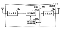
次に、図2を用いて、対象車両Bの周辺車両Aで用いられる車載機1aの概略的な構成の一例についての説明を行う。図2に示すように、車載機1aは、コントローラ11a、位置検出器12a、及び狭域通信器(車車間通信器とも言及される)13aを備えている。
次に、図2を用いて、対象車両Bの周辺車両Aで用いられる車載機1aの概略的な構成の一例についての説明を行う。図2に示すように、車載機1aは、コントローラ11a、位置検出器12a、及び狭域通信器(車車間通信器とも言及される)13aを備えている。
位置検出器12aは、GNSS(Global Navigation Satellite System)に用いられるGNSS受信機を備えており、測位衛星からアンテナで受信した信号をもとに、周辺車両Aの現在位置を逐次検出(つまり、測位)する。このGNSSは衛星測位システムとも言及され、位置検出器12aは測位機とも言及される。測位した現在位置(以下、車両位置)は、例えば緯度/経度で表すものとする。なお、位置検出器12aは、車輪速センサから出力されるパルス信号やジャイロセンサで検出するヨーレートなどによって車両位置を推測する推測航法を用いて測位結果を補完するデッドレコニング(Dead Reckoning)を行う構成としてもよい。
位置検出器12aは、GNSSを用いた測位性能に関する情報をコントローラ11aに出力する。GNSSを用いた測位性能に関する情報の一例としては、測位に用いた衛星のC/N比などの受信感度、測位時に視野内にあった可視衛星の数(以下、衛星数)、最終測位時刻、測位誤差などがある。
例えば、測位誤差としては、測位衛星からの信号の受信点から見た測位衛星の幾何学的配置に影響される測位精度劣化係数であるDOP(Dilution of Precision)を用いてもよいし、DOPの値の逆数を用いてもよい。他にも、デッドレコニングを行って測位した位置と、GNSSによって測位した位置との誤差を用いてもよい。
狭域通信器13aは、送受信用のアンテナを介して、通信範囲内に位置する車載機1bと車車間通信を行う。より詳しくは、狭域通信器13aは、コントローラ11aの指示に従って信号を送信する。
コントローラ11aは、電子制御ユニット、制御回路とも言及される。本実施形態では、一例として、CPU、ROMやRAM等のメモリ、I/O、及びこれらを接続するバスを備え、ROMに記憶された制御プログラムを実行することで各種の処理を実行する。コントローラ11aの詳細については後述する。なお、コントローラ11aが実行する機能の一部または全部を、一つあるいは複数のIC等によりハードウェア的に構成してもよい。
<コントローラ11aの概略構成>
続いて、コントローラ11aの概略的な構成の一例について説明を行う。図2に示すように、コントローラ11aは、測位性能指標取得部111a及び送信処理部112aを備えている。
続いて、コントローラ11aの概略的な構成の一例について説明を行う。図2に示すように、コントローラ11aは、測位性能指標取得部111a及び送信処理部112aを備えている。
測位性能指標取得部111aは、位置検出器12aから出力される、GNSSを用いた測位性能に関する情報(以下、測位性能指標)を取得する。測位性能指標は、前述した受信感度、衛星数、最終測位時刻、測位誤差などであって、これらのうちのいずれかを取得する構成としてもよいし、これらの全部若しくは一部の組を取得する構成としてもよい。
送信処理部112aは、測位性能指標取得部111aで取得した、位置検出器12aについての測位性能指標を、狭域通信器13aから車車間通信で送信させる。測位性能指標を送信させるタイミングは、例えば100msecごとなどの所定周期であってもよいし、所定のトリガの検出時であってもよい。所定のトリガの一例としては、車載機1aが路側機との路車間通信も行う構成とした場合には、路車間通信の開始時などがある。狭域通信器13aから測位性能指標を送信する場合には、送信元の車載機1aを識別するための機器IDなどの識別子を付与して送信すればよい。
<車載機1bの概略構成>
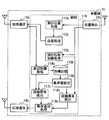
次に、図3を用いて、対象車両Bで用いられる車載機1bの概略的な構成の一例についての説明を行う。図3に示すように、車載機1bは、コントローラ11b、位置検出器12b、狭域通信器(車車/路車通信器とも言及される)13b、及び広域通信器14bを備えている。
次に、図3を用いて、対象車両Bで用いられる車載機1bの概略的な構成の一例についての説明を行う。図3に示すように、車載機1bは、コントローラ11b、位置検出器12b、狭域通信器(車車/路車通信器とも言及される)13b、及び広域通信器14bを備えている。
位置検出器12bは、便宜上、部材番号を異ならせているが、前述した位置検出器12aと同様である。つまり、衛星測位システムを用いて車載機1bを用いる対象車両Bの現在位置を測位する。よって、この位置検出器12bも、測位機とも言及される。
狭域通信器13bは、送受信用のアンテナを介して、通信範囲内に位置する車載機1aと車車間通信を行ったり、プロバイダ端末2と路車間通信を行ったりする。より詳しくは、狭域通信器13bは、コントローラ11bの指示に従って信号を送信する。この狭域通信器13bは車車間通信器とも言及される。広域通信器14bは、携帯電話網やインターネット等の通信網を介してセンタ3との間で通信を行う。
コントローラ11bは、電子制御ユニット、制御回路とも言及される。本実施形態では、一例として、CPU、ROMやRAM等のメモリ、I/O、及びこれらを接続するバスを備え、ROMに記憶された制御プログラムを実行することで各種の処理を実行する。コントローラ11bの詳細については後述する。なお、コントローラ11bが実行する機能の一部または全部を、一つあるいは複数のIC等によりハードウェア的に構成してもよい。
<コントローラ11bの概略構成>
続いて、コントローラ11bの概略的な構成の一例について説明を行う。図3に示すように、コントローラ11bは、測位位置取得部111b、測位性能指標取得部112b、送信処理部113b、周辺指標取得部114b、指標記憶器115b、基準値設定部116b、別機異常検出部117b、自機異常検出部118b、及び異常通知処理部119bを備えている。
続いて、コントローラ11bの概略的な構成の一例について説明を行う。図3に示すように、コントローラ11bは、測位位置取得部111b、測位性能指標取得部112b、送信処理部113b、周辺指標取得部114b、指標記憶器115b、基準値設定部116b、別機異常検出部117b、自機異常検出部118b、及び異常通知処理部119bを備えている。
測位位置取得部111bは、位置検出器12bで測位された車両位置を逐次取得する。測位性能指標取得部112bは、測位性能指標取得部111aと同様にして、位置検出器12bから出力される測位性能指標を取得する。
送信処理部113bは、測位位置取得部111bで取得した車両位置を、狭域通信器13bから路車間通信で送信させる。路車間通信で車両位置を送信させるタイミングは、プロバイダ端末2から路車間通信で送信されてくる信号の受信時などとすればよい。路車間通信でプロバイダ端末2に車両位置を送信することにより、車載機1bでは、プロバイダ端末2から車両位置に応じたサービスの提供を受ける。
周辺指標取得部114bでは、車載機1a(つまり、周辺車両A)から車車間通信によって送信された、その周辺車両Aの位置検出器12aについての測位性能指標を、狭域通信器13bを介して逐次取得する。そして、取得した測位性能指標を指標記憶器115bに記憶する。
周辺指標取得部114bは、異なる周辺車両Aから測位性能指標を狭域通信器13bで受信するごとに、受信した測位性能指標を指標記憶器115bに記憶する。これにより、複数台の周辺車両Aから測位性能指標を受信した場合には、複数台の周辺車両Aの位置検出器12aについての測位性能指標が指標記憶器115bに蓄積されることになる。
なお、指標記憶器115bに測位性能指標を記憶する場合には、送信元の車載機1aを識別する識別子と対応付けて記憶することで、異なる周辺車両Aから受信した測位性能指標を個別に認識できるようにすればよい。
また、周辺指標取得部114bは、指標記憶器115bに測位性能指標を記憶済みの車載機1aから測位性能指標を再度受信した場合には、新たに受信した測位性能指標で記憶済みの測位性能指標を更新すればよい。加えて、更新が例えば数秒等の一定期間行われなかった測位性能指標については指標記憶器115bから消去することで、指標記憶器115bに記憶される測位性能指標が、車載機1bの車車間通信の範囲内に位置する車載機1aの位置検出器12aについての測位性能指標に絞られるようにすればよい。
基準値設定部116bは、指標記憶器115bに記憶されている、複数台の周辺車両Aから受信した測位性能指標の集合から、この測位性能指標の集合の基準となる基準値を逐次設定する。一例としては、測位性能指標の集合の最頻値を算出し、算出した最頻値を基準値とすればよい。他にも、測位性能指標の集合の平均値を基準値としてもよいし、測位性能指標の集合の中間値を基準値としてもよい。
基準値設定部116bは、測位性能指標が複数種類である場合には、その種類別に基準値を設定する。例えば、測位性能指標の種類が受信感度の場合には、受信感度についての基準値を設定する。衛星数、最終測位時刻、測位誤差についても同様である。
基準値設定部116bは、一定周期ごとに基準値を設定すればよい。ここで言うところの一定周期は、指標記憶器115bに記憶される測位性能指標の集合に変化が生じると推定される程度の期間よりも長い時間間隔であって、任意に設定可能な時間間隔とする。また、基準値設定部116bは、指標記憶器115bに新たな測位性能指標が記憶されるごとに基準値の設定を行う構成としてもよい。
指標記憶器115bに記憶されている測位性能指標の集合は、その時点で対象車両Bの周辺に実際に位置する周辺車両Aから受信した測位性能指標の集合である。よって、基準値設定部116bは、その都度、対象車両Bの周辺に実際に位置する周辺車両Aから受信した測位性能指標の集合の基準値を設定することになる。
別機異常検出部117bは、基準値設定部116bで直近に設定した基準値と、周辺指標取得部114bで取得した、周辺車両Aの位置検出器12aについての測位性能指標とを比較する。そして、位置検出器12aについての測位性能指標が、基準値から所定値以上乖離している場合に、その位置検出器12aの異常を検出する。言い換えると、その位置検出器12aを備えている車載機1aの異常を検出する。また、基準値からの乖離が所定値未満の場合には、異常を検出しない。
自機異常検出部118bは、基準値設定部116bで直近に設定した基準値と、測位性能指標取得部112bで取得した、対象車両Bの位置検出器12bについての測位性能指標とを比較する。そして、位置検出器12bについての測位性能指標が、基準値から前述の所定値以上乖離している場合に、その位置検出器12bの異常を検出する。また、基準値からの乖離が所定値未満の場合には、異常を検出しない。
別機異常検出部117bでも、自機異常検出部118bでも、比較する対象は揃えるものとする。詳しくは、測位性能指標の種類が受信感度の場合には、受信感度についての基準値と比較する。衛星数、最終測位時刻、測位誤差についても同様である。
異常通知処理部119bは、別機異常検出部117bで周辺車両Aの位置検出器12aの異常を検出した場合に、その周辺車両Aの位置検出器12aの異常を検出したことを広域通信器14bからセンタ3に向けて広域通信によって通知させる。また、異常通知処理部119bは、自機異常検出部118bで対象車両Bの位置検出器12bの異常を検出した場合に、対象車両Bの位置検出器12bの異常を検出したことを広域通信器14bからセンタ3に向けて広域通信によって通知させる。異常を検出したことを示す通知を受信したセンタ3では、例えばオペレータ等が異常への対処を行う。
なお、位置検出器12aや位置検出器12bの異常を検出して通知する構成に限らず、位置検出器12aや位置検出器12bの異常を検出した場合に、その位置検出器12aや位置検出器12bを備えている車載機1aや車載機1bの異常を検出して、車載機1aや車載機1bの異常を通知する構成としてもよい。
<コントローラ11bでの基準値設定関連処理>
続いて、図4のフローチャートを用いて、コントローラ11bでの基準値の設定に関連する基準値設定関連処理の流れの一例について説明を行う。
続いて、図4のフローチャートを用いて、コントローラ11bでの基準値の設定に関連する基準値設定関連処理の流れの一例について説明を行う。
記載されるフローチャートは、複数のセクション(あるいはステップと言及される)を含み、各セクションは、たとえば、S1と表現される。さらに、各セクションは、複数のサブセクションに分割されることができる、一方、複数のセクションが合わさって一つのセクションにすることも可能である。各セクションは、デバイス、モジュール、ユニット、あるいは、固有名(例:ディテクター)として、言及されることができる。また、セクションは、(i)ハードウエアユニット(例えば、コンピュータ)と組み合わさったソフトウエアのセクションのみならず、(ii)ハードウエア(例えば、集積回路、配線論理回路)のセクションとして、関連する装置の機能を含みあるいは含まずに実現できる。さらに、ハードウエアのセクションは、マイクロコンピュータの内部に含まれることもできる。
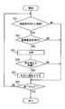
図4のフローチャートは、対象車両Bのイグニッション電源がオンになったときに開始する構成とすればよい。まず、S1では、周辺指標取得部114bが、周辺車両Aから車車間通信によって送信された、その周辺車両Aの位置検出器12aについての測位性能指標を、狭域通信器13bを介して取得した場合(S1でYES)には、S2に移る。一方、取得していない場合(S1でNO)には、S6に移る。S2では、周辺指標取得部114bが、取得した測位性能指標を指標記憶器115bに記憶する。
S3では、基準値設定部116bで基準値を設定するタイミングであった場合(S3でYES)には、S4に移る。一方、基準値を設定するタイミングでなかった場合は、S6に移る。基準値設定部116bで基準値を設定するタイミングは、前述した一定周期ごとであってもよいし、指標記憶器115bに新たな測位性能指標が記憶されたときであってもよい。
S4では、指標記憶器115bに記憶されている測位性能指標の数が所定の複数以上であった場合(S4でYES)には、S5に移る。一方、記憶されている測位性能指標の数が所定の複数未満であった場合(S4でNO)には、S6に移る。
ここで言うところの所定の複数とは、指標記憶器115bに記憶されている測位性能指標の集合から基準値設定部116bで設定される基準値に求める信頼度を考慮して定める値である。これにより、十分な信頼度のある基準値を設定できるだけの測位性能指標の母数に達していない場合には、基準値の設定を行わず、別機異常検出部117bや自機異常検出部118bでの誤検出を防止することが可能になる。
S5では、基準値設定部116bが、指標記憶器115bに記憶されている、複数台の周辺車両Aから受信した測位性能指標の集合から、この測位性能指標の集合の基準となる基準値を設定する。
S6では、基準値設定関連処理の終了タイミングであった場合(S6でYES)には、基準値設定関連処理を終了する。一方、基準値設定関連処理の終了タイミングでなかった場合(S6でNO)には、S1に戻って処理を繰り返す。基準値設定関連処理の終了タイミングの一例としては、対象車両Bのイグニッション電源がオフになったときなどがある。
<コントローラ11bでの別機異常検出関連処理>
続いて、図5のフローチャートを用いて、コントローラ11bでの別機異常検出関連処理の流れの一例について説明を行う。別機異常検出関連処理は、周辺車両Aの位置検出器12aについての異常の検出に関連する処理である。図5のフローチャートは、対象車両Bのイグニッション電源がオンになったときに開始する構成とすればよい。
続いて、図5のフローチャートを用いて、コントローラ11bでの別機異常検出関連処理の流れの一例について説明を行う。別機異常検出関連処理は、周辺車両Aの位置検出器12aについての異常の検出に関連する処理である。図5のフローチャートは、対象車両Bのイグニッション電源がオンになったときに開始する構成とすればよい。
まず、S21では、周辺指標取得部114bが、周辺車両Aから車車間通信によって送信された、その周辺車両Aの位置検出器12aについての測位性能指標を、狭域通信器13bを介して取得した場合(S21でYES)には、S22に移る。一方、取得していない場合(S21でNO)には、S26に移る。
S22では、基準値設定関連処理で基準値を設定済みであった場合(S22でYES)には、S23に移る。一方、基準値設定関連処理で基準値を設定済みでなかった場合(S22でNO)には、S26に移る。
S23では、別機異常検出部117bが、基準値設定関連処理で設定済みの直近の基準値と、S21で取得した診断ターゲットとしての周辺車両A(ターゲット周辺車両とも言及される)の位置検出器12aについての測位性能指標とを比較する。
S24では、S23での比較の結果、S21で取得した周辺車両Aの位置検出器12aについての測位性能指標が、基準値から所定値以上乖離している場合(S24でYES)には、その周辺車両Aの位置検出器12aの異常を検出し、S25に移る。一方、基準値からの乖離が所定値未満であった場合(S24でNO)には、その周辺車両Aの位置検出器12aの異常を検出せず、S26に移る。ここで言うところの所定値とは、異常が生じていると言える程度の値であって、任意に設定可能な値である。
S25では、異常通知処理部119bが、S21で測位性能指標を取得した周辺車両Aについて、位置検出器12aの異常を検出したことを広域通信器14bからセンタ3に向けて広域通信によって通知させる。
S26では、別機異常検出関連処理の終了タイミングであった場合(S26でYES)には、別機異常検出関連処理を終了する。一方、別機異常検出関連処理の終了タイミングでなかった場合(S26でNO)には、S21に戻って処理を繰り返す。別機異常検出関連処理の終了タイミングの一例としては、対象車両Bのイグニッション電源がオフになったときなどがある。
<コントローラ11bでの自機異常検出関連処理>
続いて、図6のフローチャートを用いて、コントローラ11bでの自機異常検出関連処理の流れの一例について説明を行う。自機異常検出関連処理は、対象車両Bの位置検出器12bについての異常の検出に関連する処理である。図6のフローチャートは、対象車両Bのイグニッション電源がオンになったときに開始する構成とすればよい。
続いて、図6のフローチャートを用いて、コントローラ11bでの自機異常検出関連処理の流れの一例について説明を行う。自機異常検出関連処理は、対象車両Bの位置検出器12bについての異常の検出に関連する処理である。図6のフローチャートは、対象車両Bのイグニッション電源がオンになったときに開始する構成とすればよい。
まず、S41では、測位性能指標取得部112bが、位置検出器12bから出力される測位性能指標を取得する。S42では、基準値設定関連処理で基準値を設定済みであった場合(S42でYES)には、S43に移る。一方、基準値設定関連処理で基準値を設定済みでなかった場合(S42でNO)には、S46に移る。
S43では、自機異常検出部118bが、基準値設定関連処理で設定済みの直近の基準値と、S41で取得した対象車両Bの位置検出器12bについての測位性能指標とを比較する。
S44では、S43での比較の結果、S41で取得した対象車両Bの位置検出器12bについての測位性能指標が、基準値から所定値以上乖離している場合(S44でYES)には、対象車両Bの位置検出器12bの異常を検出し、S45に移る。一方、基準値からの乖離が所定値未満であった場合(S44でNO)には、対象車両Bの位置検出器12bの異常を検出せず、S46に移る。
S45では、異常通知処理部119bが、対象車両Bの位置検出器12bの異常を検出したことを広域通信器14bからセンタ3に向けて広域通信によって通知させる。
S46では、自機異常検出関連処理の終了タイミングであった場合(S46でYES)には、自機異常検出関連処理を終了する。一方、自機異常検出関連処理の終了タイミングでなかった場合(S46でNO)には、S41に戻って処理を繰り返す。自機異常検出関連処理の終了タイミングの一例としては、対象車両Bのイグニッション電源がオフになったときなどがある。
<実施形態1のまとめ>
実施形態1の構成によれば、基準値設定部116bで設定する基準値は、その時点で対象車両Bと車車間通信可能な程度に近辺に位置する周辺車両Aから受信した測位性能指標の集合の基準となる値である。よって、対象車両Bの近辺に絞られた領域で環境要因による測位性能の低下が生じた場合といった、一部の周辺車両Aや対象車両Bに限られない測位性能の低下が生じている場合には、この測位性能の低下に合わせて基準値も変動する。一方、測位機の異常による一部の周辺車両Aや対象車両Bに限られた測位性能の低下については、基準値への影響は緩和されるため、基準値の変動が抑えられる。従って、この基準値と測位性能指標とを比較することによって、一部の周辺車両Aや対象車両Bに限られない測位性能の低下と区別して、位置検出器12aや位置検出器12bの異常を精度良く検出することが可能になる。
実施形態1の構成によれば、基準値設定部116bで設定する基準値は、その時点で対象車両Bと車車間通信可能な程度に近辺に位置する周辺車両Aから受信した測位性能指標の集合の基準となる値である。よって、対象車両Bの近辺に絞られた領域で環境要因による測位性能の低下が生じた場合といった、一部の周辺車両Aや対象車両Bに限られない測位性能の低下が生じている場合には、この測位性能の低下に合わせて基準値も変動する。一方、測位機の異常による一部の周辺車両Aや対象車両Bに限られた測位性能の低下については、基準値への影響は緩和されるため、基準値の変動が抑えられる。従って、この基準値と測位性能指標とを比較することによって、一部の周辺車両Aや対象車両Bに限られない測位性能の低下と区別して、位置検出器12aや位置検出器12bの異常を精度良く検出することが可能になる。
実施形態1の構成によれば、別機異常検出部117bでは、基準値設定部116bで設定した基準値と、周辺車両Aから狭域通信器13bで受信したその周辺車両Aの位置検出器12aについての測位性能指標とを比較することによって、その周辺車両Aの位置検出器12aの異常を検出するので、その周辺車両Aの位置検出器12aの異常を精度良く検出することが可能になる。
また、実施形態1の構成によれば、自機異常検出部118bでは、基準値設定部116bで設定した基準値と、対象車両Bから測位性能指標取得部112bで取得した対象車両Bの位置検出器12bについての測位性能指標とを比較することによって、対象車両Bの位置検出器12bの異常を検出するので、対象車両Bの位置検出器12bの異常を精度良く検出することが可能になる。
さらに、実施形態1の構成によれば、周辺車両Aの位置検出器12aや対象車両Bの位置検出器12bの異常をセンタ3に通知するので、センタ3においてそれらの異常に対するアフターサービスを迅速に行うことが可能になる。また、実施形態1の構成によれば、対象車両Bの車載機1bが、周辺車両Aの位置検出器12aの異常を検出したことを広域通信器14bからセンタ3に向けて広域通信によって通知させる。よって、周辺車両Aにセンタ3と通信を行う装置が搭載されていない場合や、その装置が故障している場合であっても、周辺車両Aの位置検出器12aの異常をセンタに通知することが可能になる。
(変形例1)
実施形態1では、複数台の周辺車両Aから受信した測位性能指標の集合から、基準値設定部116bで基準値を設定する構成を示したが、必ずしもこれに限らない。例えば、複数台の周辺車両Aから受信した測位性能指標と、測位性能指標取得部112bで取得した対象車両Bの位置検出器12bについての測位性能指標との集合から、基準値設定部116bで基準値を設定する構成としてもよい。この場合、測位性能指標取得部112bで取得した対象車両Bの位置検出器12bについての測位性能指標も、指標記憶器115bに記憶する構成とすればよい。
実施形態1では、複数台の周辺車両Aから受信した測位性能指標の集合から、基準値設定部116bで基準値を設定する構成を示したが、必ずしもこれに限らない。例えば、複数台の周辺車両Aから受信した測位性能指標と、測位性能指標取得部112bで取得した対象車両Bの位置検出器12bについての測位性能指標との集合から、基準値設定部116bで基準値を設定する構成としてもよい。この場合、測位性能指標取得部112bで取得した対象車両Bの位置検出器12bについての測位性能指標も、指標記憶器115bに記憶する構成とすればよい。
(変形例2)
実施形態1では、別機異常検出部117bや自機異常検出部118bで検出した異常を異常通知処理部119bが広域通信によってセンタ3に通知させる構成を示したが、必ずしもこれに限らない。例えば、別機異常検出部117bや自機異常検出部118bで検出した異常を対象車両Bにおいて表示や音声によって報知させる構成としてもよい。
実施形態1では、別機異常検出部117bや自機異常検出部118bで検出した異常を異常通知処理部119bが広域通信によってセンタ3に通知させる構成を示したが、必ずしもこれに限らない。例えば、別機異常検出部117bや自機異常検出部118bで検出した異常を対象車両Bにおいて表示や音声によって報知させる構成としてもよい。
(変形例3)
実施形態1では、車載機1bが別機異常検出部117bと自機異常検出部118bとを備える構成を示したが、必ずしもこれに限らない。例えば、車載機1bが自機異常検出部118bを備えず、対象車両Bの位置検出器12bについての異常の検出を行わない構成としてもよい。この場合、車載機1bは、自機異常検出部118bの他に、測位性能指標取得部112bも備えない構成としてもよい。
実施形態1では、車載機1bが別機異常検出部117bと自機異常検出部118bとを備える構成を示したが、必ずしもこれに限らない。例えば、車載機1bが自機異常検出部118bを備えず、対象車両Bの位置検出器12bについての異常の検出を行わない構成としてもよい。この場合、車載機1bは、自機異常検出部118bの他に、測位性能指標取得部112bも備えない構成としてもよい。
(変形例4)
実施形態1では、車載機1bが別機異常検出部117bと自機異常検出部118bとを備える構成を示したが、必ずしもこれに限らない。例えば、車載機1bが別機異常検出部117bを備えず、周辺車両Aの位置検出器12aについての異常の検出を行わない構成としてもよい。
実施形態1では、車載機1bが別機異常検出部117bと自機異常検出部118bとを備える構成を示したが、必ずしもこれに限らない。例えば、車載機1bが別機異常検出部117bを備えず、周辺車両Aの位置検出器12aについての異常の検出を行わない構成としてもよい。
(変形例5)
また、車載機1aの有する機能と車載機1bの有する機能との両方を有する車載機を対象車両B及び周辺車両Aで用いる構成としてもよい。つまり、車載機1aが、測位位置取得部111b、送信処理部113b、周辺指標取得部114b、指標記憶器115b、基準値設定部116b、別機異常検出部117b、自機異常検出部118b、及び異常通知処理部119bと同様の処理を行う機能を備える構成としてもよい。また、車載機1bが、送信処理部112aと同様の処理を行う機能を備える構成としてもよい。
また、車載機1aの有する機能と車載機1bの有する機能との両方を有する車載機を対象車両B及び周辺車両Aで用いる構成としてもよい。つまり、車載機1aが、測位位置取得部111b、送信処理部113b、周辺指標取得部114b、指標記憶器115b、基準値設定部116b、別機異常検出部117b、自機異常検出部118b、及び異常通知処理部119bと同様の処理を行う機能を備える構成としてもよい。また、車載機1bが、送信処理部112aと同様の処理を行う機能を備える構成としてもよい。
(変形例6)
実施形態1では、プロバイダ端末2が路側に設置された路側機である場合を例に挙げて説明を行ったが、必ずしもこれに限らない。例えば、プロバイダ端末2は、自動車などの移動体に搭載されている構成としてもよい。
実施形態1では、プロバイダ端末2が路側に設置された路側機である場合を例に挙げて説明を行ったが、必ずしもこれに限らない。例えば、プロバイダ端末2は、自動車などの移動体に搭載されている構成としてもよい。
本開示は、実施例に準拠して記述されたが、本開示は当該実施例や構造に限定されるものではないと理解される。本開示は、様々な変形例や均等範囲内の変形をも包含する。加えて、様々な組み合わせや形態、さらには、それらに一要素のみ、それ以上、あるいはそれ以下、を含む他の組み合わせや形態をも、本開示の範疇や思想範囲に入るものである
Claims (6)
- 対象車両とその周辺の複数の周辺車両とを含む、複数のホスト車両の、それぞれで用いられ、
衛星測位システムを用いて各ホスト車両の現在位置を測位する測位機(12a、12b)と、
車車間通信によって情報を送受信する車車間通信器(13a,13b)を備える車載機であって、
前記対象車両で用いられる前記車載機は、
前記車車間通信器を介して、送信されてくる、前記複数の周辺車両のそれぞれの現在位置を測位する前記測位機(12a)についての測位性能を表す指標である別機測位性能指標を受信し、
前記複数の周辺車両から受信した前記別機測位性能指標から、測位性能指標の基準値を逐次設定する基準値設定部(116b)と、
前記基準値設定部で設定した前記基準値と、前記複数の周辺車両のうち、所定の診断ターゲットとなるターゲット周辺車両の前記測位機についての前記別機測位性能指標とを比較することによって、前記ターゲット周辺車両の前記測位機の異常を検出する別機異常検出部(117b)と、を備える
車載機。 - 請求項1において、
前記対象車両で用いられる前記車載機は、
前記対象車両の前記測位機についての自機測位性能指標を取得する測位性能指標取得部(112b)と、
前記基準値設定部で設定した前記基準値と、前記測位性能指標取得部で取得した前記対象車両の前記測位機についての前記自機測位性能指標とを比較することによって、前記対象車両の前記測位機の異常を検出する自機異常検出部(118b)とを備える
車載機。 - 請求項2において、
前記対象車両で用いられる前記車載機は、
センタ(3)と通信網を介した通信を行う広域通信器(14b)と、
前記自機異常検出部で前記対象車両の前記測位機の異常を検出した場合に、前記対象車両の前記測位機の異常を検出したことを前記広域通信器から前記センタに向けて通知させる異常通知処理部(119b)とを備える
車載機。 - 請求項1又は2において、
前記対象車両で用いられる前記車載機は、
センタ(3)と通信網を介した通信を行う広域通信器(14b)と、
前記別機異常検出部で前記ターゲット周辺車両の前記測位機の異常を検出した場合に、前記ターゲット周辺車両の前記測位機の異常を検出したことを前記広域通信器から前記センタに向けて通知させる異常通知処理部(119b)とを備える
車載機。 - 対象車両とその周辺の少なくとも一つの周辺車両とを含む複数のホスト車両の、それぞれで用いられ、
衛星測位システムを用いて各ホスト車両の現在位置を測位する測位機(12a、12b)と、
車車間通信によって情報を送受信する車車間通信器(13a,13b)とを備える車載機であって、
前記対象車両で用いられる前記車載機は、
前記車車間通信器を介して、送信されてくる、前記少なくとも一つの周辺車両のそれぞれで用いられる前記測位機(12a)についての測位性能を表す指標である別機測位性能指標を受信し、
前記少なくとも一つの周辺車両からそれぞれ受信した前記別機測位性能指標から、測位性能指標の基準値を逐次設定する基準値設定部(116b)と、
前記対象車両の前記測位機についての自機測位性能指標を取得する測位性能指標取得部(112b)と、
前記基準値設定部で設定した前記基準値と、前記測位性能指標取得部で取得した前記対象車両の前記測位機についての前記自機測位性能指標とを比較することによって、前記対象車両の前記測位機の異常を検出する自機異常検出部(118b)とを備える
車載機。 - 請求項5において、
前記対象車両で用いられる前記車載機は、
センタ(3)と通信網を介した通信を行う広域通信器(14b)と、
前記自機異常検出部で前記対象車両の前記測位機の異常を検出した場合に、前記対象車両の前記測位機の異常を検出したことを前記広域通信器から前記センタに向けて通知させる異常通知処理部(119b)とを備える
車載機。
Applications Claiming Priority (2)
| Application Number | Priority Date | Filing Date | Title |
|---|---|---|---|
| JP2015-006176 | 2015-01-15 | ||
| JP2015006176A JP2016133316A (ja) | 2015-01-15 | 2015-01-15 | 車載機 |
Publications (1)
| Publication Number | Publication Date |
|---|---|
| WO2016113815A1 true WO2016113815A1 (ja) | 2016-07-21 |
Family
ID=56405383
Family Applications (1)
| Application Number | Title | Priority Date | Filing Date |
|---|---|---|---|
| PCT/JP2015/006368 Ceased WO2016113815A1 (ja) | 2015-01-15 | 2015-12-22 | 車載機 |
Country Status (2)
| Country | Link |
|---|---|
| JP (1) | JP2016133316A (ja) |
| WO (1) | WO2016113815A1 (ja) |
Cited By (1)
| Publication number | Priority date | Publication date | Assignee | Title |
|---|---|---|---|---|
| CN113359094A (zh) * | 2020-03-06 | 2021-09-07 | 本田技研工业株式会社 | 车辆用信息处理装置 |
Families Citing this family (2)
| Publication number | Priority date | Publication date | Assignee | Title |
|---|---|---|---|---|
| US11333736B2 (en) | 2017-12-25 | 2022-05-17 | Nec Corporation | Position measurement device and method, and recording medium |
| KR102488643B1 (ko) * | 2019-09-11 | 2023-01-16 | 한국도로공사 | 측위 차이를 이용한 정밀 위치 보정 장치 및 그 방법 |
Citations (4)
| Publication number | Priority date | Publication date | Assignee | Title |
|---|---|---|---|---|
| JPH11183588A (ja) * | 1997-12-17 | 1999-07-09 | Mazda Motor Corp | 移動体用ディファレンシャルgps装置 |
| JP2005072889A (ja) * | 2003-08-22 | 2005-03-17 | Matsushita Electric Works Ltd | Gps通信一体型システム |
| JP2011211336A (ja) * | 2010-03-29 | 2011-10-20 | Japan Radio Co Ltd | 無線通信機 |
| WO2014020949A1 (ja) * | 2012-08-01 | 2014-02-06 | 日本電気株式会社 | 通信装置、通信機、通信システム、通信方法、位置特定方法および記録媒体 |
-
2015
- 2015-01-15 JP JP2015006176A patent/JP2016133316A/ja active Pending
- 2015-12-22 WO PCT/JP2015/006368 patent/WO2016113815A1/ja not_active Ceased
Patent Citations (4)
| Publication number | Priority date | Publication date | Assignee | Title |
|---|---|---|---|---|
| JPH11183588A (ja) * | 1997-12-17 | 1999-07-09 | Mazda Motor Corp | 移動体用ディファレンシャルgps装置 |
| JP2005072889A (ja) * | 2003-08-22 | 2005-03-17 | Matsushita Electric Works Ltd | Gps通信一体型システム |
| JP2011211336A (ja) * | 2010-03-29 | 2011-10-20 | Japan Radio Co Ltd | 無線通信機 |
| WO2014020949A1 (ja) * | 2012-08-01 | 2014-02-06 | 日本電気株式会社 | 通信装置、通信機、通信システム、通信方法、位置特定方法および記録媒体 |
Cited By (1)
| Publication number | Priority date | Publication date | Assignee | Title |
|---|---|---|---|---|
| CN113359094A (zh) * | 2020-03-06 | 2021-09-07 | 本田技研工业株式会社 | 车辆用信息处理装置 |
Also Published As
| Publication number | Publication date |
|---|---|
| JP2016133316A (ja) | 2016-07-25 |
Similar Documents
| Publication | Publication Date | Title |
|---|---|---|
| CN107209986B (zh) | 车载设备 | |
| EP3605489B1 (en) | Processing device and method for generating object identification information | |
| WO2016110915A1 (ja) | 車載機、車載機診断システム | |
| WO2016116991A1 (ja) | 車載機、車載機診断システム | |
| JP5894865B2 (ja) | 車両位置検出装置、及びプログラム | |
| JP6493181B2 (ja) | 衝突判定装置 | |
| JP6398758B2 (ja) | 車両用通信機 | |
| WO2015079630A1 (ja) | 運転支援ユニット及び運転支援システム | |
| JP2016144078A (ja) | 車両用通信機 | |
| JP2016066144A (ja) | 路面情報収集装置および路面情報解析システム | |
| JP2017135603A (ja) | 歩行者位置検出システム、車載注意喚起装置、携帯情報端末、および歩行者位置検出方法 | |
| CN109425882A (zh) | 用于定位误差检测的方法和设备 | |
| WO2016113815A1 (ja) | 車載機 | |
| CN107211252B (zh) | 车辆用通信机 | |
| JP2009289223A (ja) | 交通状況予測システム、ナビゲーション装置及びサーバ | |
| JP2016118412A (ja) | 車載機 | |
| US11899040B2 (en) | Estimation of speed of a vehicle based on light intensity measurements | |
| JP2018205894A (ja) | 判定システム、車載通信機、判定装置、判定方法および判定プログラム | |
| JP4357266B2 (ja) | レーダ装置及びレーダ装置の異常判定方法 | |
| JP2017182196A (ja) | 接近車両検出装置 | |
| JP2016043749A (ja) | タイヤ空気圧異常報知装置およびタイヤ空気圧異常報知方法 | |
| JP2008002967A (ja) | 運転支援システム | |
| JP4575246B2 (ja) | 親局制御運行支援及び管理方法、移動体の位置決め方法 | |
| JP2016143087A (ja) | 位置検出システム及び車載情報処理装置 | |
| JP2008123091A (ja) | 路車間通信装置 |
Legal Events
| Date | Code | Title | Description |
|---|---|---|---|
| 121 | Ep: the epo has been informed by wipo that ep was designated in this application |
Ref document number: 15877770 Country of ref document: EP Kind code of ref document: A1 |
|
| NENP | Non-entry into the national phase |
Ref country code: DE |
|
| 122 | Ep: pct application non-entry in european phase |
Ref document number: 15877770 Country of ref document: EP Kind code of ref document: A1 |