WO2016111188A1 - 液化ガス用冷却装置 - Google Patents
液化ガス用冷却装置 Download PDFInfo
- Publication number
- WO2016111188A1 WO2016111188A1 PCT/JP2015/086134 JP2015086134W WO2016111188A1 WO 2016111188 A1 WO2016111188 A1 WO 2016111188A1 JP 2015086134 W JP2015086134 W JP 2015086134W WO 2016111188 A1 WO2016111188 A1 WO 2016111188A1
- Authority
- WO
- WIPO (PCT)
- Prior art keywords
- compressor
- liquefied gas
- maintenance
- refrigeration
- cooling device
- Prior art date
- Legal status (The legal status is an assumption and is not a legal conclusion. Google has not performed a legal analysis and makes no representation as to the accuracy of the status listed.)
- Ceased
Links
Images


Classifications
-
- F—MECHANICAL ENGINEERING; LIGHTING; HEATING; WEAPONS; BLASTING
- F25—REFRIGERATION OR COOLING; COMBINED HEATING AND REFRIGERATION SYSTEMS; HEAT PUMP SYSTEMS; MANUFACTURE OR STORAGE OF ICE; LIQUEFACTION SOLIDIFICATION OF GASES
- F25J—LIQUEFACTION, SOLIDIFICATION OR SEPARATION OF GASES OR GASEOUS OR LIQUEFIED GASEOUS MIXTURES BY PRESSURE AND COLD TREATMENT OR BY BRINGING THEM INTO THE SUPERCRITICAL STATE
- F25J1/00—Processes or apparatus for liquefying or solidifying gases or gaseous mixtures
- F25J1/02—Processes or apparatus for liquefying or solidifying gases or gaseous mixtures requiring the use of refrigeration, e.g. of helium or hydrogen ; Details and kind of the refrigeration system used; Integration with other units or processes; Controlling aspects of the process
- F25J1/0243—Start-up or control of the process; Details of the apparatus used; Details of the refrigerant compression system used
- F25J1/0279—Compression of refrigerant or internal recycle fluid, e.g. kind of compressor, accumulator, suction drum etc.
- F25J1/0298—Safety aspects and control of the refrigerant compression system, e.g. anti-surge control
-
- F—MECHANICAL ENGINEERING; LIGHTING; HEATING; WEAPONS; BLASTING
- F25—REFRIGERATION OR COOLING; COMBINED HEATING AND REFRIGERATION SYSTEMS; HEAT PUMP SYSTEMS; MANUFACTURE OR STORAGE OF ICE; LIQUEFACTION SOLIDIFICATION OF GASES
- F25J—LIQUEFACTION, SOLIDIFICATION OR SEPARATION OF GASES OR GASEOUS OR LIQUEFIED GASEOUS MIXTURES BY PRESSURE AND COLD TREATMENT OR BY BRINGING THEM INTO THE SUPERCRITICAL STATE
- F25J1/00—Processes or apparatus for liquefying or solidifying gases or gaseous mixtures
- F25J1/0002—Processes or apparatus for liquefying or solidifying gases or gaseous mixtures characterised by the fluid to be liquefied
- F25J1/0022—Hydrocarbons, e.g. natural gas
-
- F—MECHANICAL ENGINEERING; LIGHTING; HEATING; WEAPONS; BLASTING
- F25—REFRIGERATION OR COOLING; COMBINED HEATING AND REFRIGERATION SYSTEMS; HEAT PUMP SYSTEMS; MANUFACTURE OR STORAGE OF ICE; LIQUEFACTION SOLIDIFICATION OF GASES
- F25J—LIQUEFACTION, SOLIDIFICATION OR SEPARATION OF GASES OR GASEOUS OR LIQUEFIED GASEOUS MIXTURES BY PRESSURE AND COLD TREATMENT OR BY BRINGING THEM INTO THE SUPERCRITICAL STATE
- F25J1/00—Processes or apparatus for liquefying or solidifying gases or gaseous mixtures
- F25J1/003—Processes or apparatus for liquefying or solidifying gases or gaseous mixtures characterised by the kind of cold generation within the liquefaction unit for compensating heat leaks and liquid production
- F25J1/0047—Processes or apparatus for liquefying or solidifying gases or gaseous mixtures characterised by the kind of cold generation within the liquefaction unit for compensating heat leaks and liquid production using an "external" refrigerant stream in a closed vapor compression cycle
- F25J1/0052—Processes or apparatus for liquefying or solidifying gases or gaseous mixtures characterised by the kind of cold generation within the liquefaction unit for compensating heat leaks and liquid production using an "external" refrigerant stream in a closed vapor compression cycle by vaporising a liquid refrigerant stream
- F25J1/0057—Processes or apparatus for liquefying or solidifying gases or gaseous mixtures characterised by the kind of cold generation within the liquefaction unit for compensating heat leaks and liquid production using an "external" refrigerant stream in a closed vapor compression cycle by vaporising a liquid refrigerant stream after expansion of the liquid refrigerant stream with extraction of work
-
- F—MECHANICAL ENGINEERING; LIGHTING; HEATING; WEAPONS; BLASTING
- F25—REFRIGERATION OR COOLING; COMBINED HEATING AND REFRIGERATION SYSTEMS; HEAT PUMP SYSTEMS; MANUFACTURE OR STORAGE OF ICE; LIQUEFACTION SOLIDIFICATION OF GASES
- F25J—LIQUEFACTION, SOLIDIFICATION OR SEPARATION OF GASES OR GASEOUS OR LIQUEFIED GASEOUS MIXTURES BY PRESSURE AND COLD TREATMENT OR BY BRINGING THEM INTO THE SUPERCRITICAL STATE
- F25J1/00—Processes or apparatus for liquefying or solidifying gases or gaseous mixtures
- F25J1/02—Processes or apparatus for liquefying or solidifying gases or gaseous mixtures requiring the use of refrigeration, e.g. of helium or hydrogen ; Details and kind of the refrigeration system used; Integration with other units or processes; Controlling aspects of the process
- F25J1/0228—Coupling of the liquefaction unit to other units or processes, so-called integrated processes
- F25J1/0235—Heat exchange integration
- F25J1/0236—Heat exchange integration providing refrigeration for different processes treating not the same feed stream
-
- F—MECHANICAL ENGINEERING; LIGHTING; HEATING; WEAPONS; BLASTING
- F25—REFRIGERATION OR COOLING; COMBINED HEATING AND REFRIGERATION SYSTEMS; HEAT PUMP SYSTEMS; MANUFACTURE OR STORAGE OF ICE; LIQUEFACTION SOLIDIFICATION OF GASES
- F25J—LIQUEFACTION, SOLIDIFICATION OR SEPARATION OF GASES OR GASEOUS OR LIQUEFIED GASEOUS MIXTURES BY PRESSURE AND COLD TREATMENT OR BY BRINGING THEM INTO THE SUPERCRITICAL STATE
- F25J1/00—Processes or apparatus for liquefying or solidifying gases or gaseous mixtures
- F25J1/02—Processes or apparatus for liquefying or solidifying gases or gaseous mixtures requiring the use of refrigeration, e.g. of helium or hydrogen ; Details and kind of the refrigeration system used; Integration with other units or processes; Controlling aspects of the process
- F25J1/0243—Start-up or control of the process; Details of the apparatus used; Details of the refrigerant compression system used
- F25J1/0244—Operation; Control and regulation; Instrumentation
- F25J1/0245—Different modes, i.e. 'runs', of operation; Process control
- F25J1/0248—Stopping of the process, e.g. defrosting or deriming, maintenance; Back-up mode or systems
-
- F—MECHANICAL ENGINEERING; LIGHTING; HEATING; WEAPONS; BLASTING
- F25—REFRIGERATION OR COOLING; COMBINED HEATING AND REFRIGERATION SYSTEMS; HEAT PUMP SYSTEMS; MANUFACTURE OR STORAGE OF ICE; LIQUEFACTION SOLIDIFICATION OF GASES
- F25J—LIQUEFACTION, SOLIDIFICATION OR SEPARATION OF GASES OR GASEOUS OR LIQUEFIED GASEOUS MIXTURES BY PRESSURE AND COLD TREATMENT OR BY BRINGING THEM INTO THE SUPERCRITICAL STATE
- F25J1/00—Processes or apparatus for liquefying or solidifying gases or gaseous mixtures
- F25J1/02—Processes or apparatus for liquefying or solidifying gases or gaseous mixtures requiring the use of refrigeration, e.g. of helium or hydrogen ; Details and kind of the refrigeration system used; Integration with other units or processes; Controlling aspects of the process
- F25J1/0243—Start-up or control of the process; Details of the apparatus used; Details of the refrigerant compression system used
- F25J1/0244—Operation; Control and regulation; Instrumentation
- F25J1/0252—Control strategy, e.g. advanced process control or dynamic modeling
-
- F—MECHANICAL ENGINEERING; LIGHTING; HEATING; WEAPONS; BLASTING
- F25—REFRIGERATION OR COOLING; COMBINED HEATING AND REFRIGERATION SYSTEMS; HEAT PUMP SYSTEMS; MANUFACTURE OR STORAGE OF ICE; LIQUEFACTION SOLIDIFICATION OF GASES
- F25J—LIQUEFACTION, SOLIDIFICATION OR SEPARATION OF GASES OR GASEOUS OR LIQUEFIED GASEOUS MIXTURES BY PRESSURE AND COLD TREATMENT OR BY BRINGING THEM INTO THE SUPERCRITICAL STATE
- F25J1/00—Processes or apparatus for liquefying or solidifying gases or gaseous mixtures
- F25J1/02—Processes or apparatus for liquefying or solidifying gases or gaseous mixtures requiring the use of refrigeration, e.g. of helium or hydrogen ; Details and kind of the refrigeration system used; Integration with other units or processes; Controlling aspects of the process
- F25J1/0243—Start-up or control of the process; Details of the apparatus used; Details of the refrigerant compression system used
- F25J1/0257—Construction and layout of liquefaction equipments, e.g. valves, machines
- F25J1/0269—Arrangement of liquefaction units or equipments fulfilling the same process step, e.g. multiple "trains" concept
-
- F—MECHANICAL ENGINEERING; LIGHTING; HEATING; WEAPONS; BLASTING
- F25—REFRIGERATION OR COOLING; COMBINED HEATING AND REFRIGERATION SYSTEMS; HEAT PUMP SYSTEMS; MANUFACTURE OR STORAGE OF ICE; LIQUEFACTION SOLIDIFICATION OF GASES
- F25J—LIQUEFACTION, SOLIDIFICATION OR SEPARATION OF GASES OR GASEOUS OR LIQUEFIED GASEOUS MIXTURES BY PRESSURE AND COLD TREATMENT OR BY BRINGING THEM INTO THE SUPERCRITICAL STATE
- F25J1/00—Processes or apparatus for liquefying or solidifying gases or gaseous mixtures
- F25J1/02—Processes or apparatus for liquefying or solidifying gases or gaseous mixtures requiring the use of refrigeration, e.g. of helium or hydrogen ; Details and kind of the refrigeration system used; Integration with other units or processes; Controlling aspects of the process
- F25J1/0243—Start-up or control of the process; Details of the apparatus used; Details of the refrigerant compression system used
- F25J1/0279—Compression of refrigerant or internal recycle fluid, e.g. kind of compressor, accumulator, suction drum etc.
- F25J1/0281—Compression of refrigerant or internal recycle fluid, e.g. kind of compressor, accumulator, suction drum etc. characterised by the type of prime driver, e.g. hot gas expander
- F25J1/0284—Electrical motor as the prime mechanical driver
-
- F—MECHANICAL ENGINEERING; LIGHTING; HEATING; WEAPONS; BLASTING
- F25—REFRIGERATION OR COOLING; COMBINED HEATING AND REFRIGERATION SYSTEMS; HEAT PUMP SYSTEMS; MANUFACTURE OR STORAGE OF ICE; LIQUEFACTION SOLIDIFICATION OF GASES
- F25J—LIQUEFACTION, SOLIDIFICATION OR SEPARATION OF GASES OR GASEOUS OR LIQUEFIED GASEOUS MIXTURES BY PRESSURE AND COLD TREATMENT OR BY BRINGING THEM INTO THE SUPERCRITICAL STATE
- F25J1/00—Processes or apparatus for liquefying or solidifying gases or gaseous mixtures
- F25J1/02—Processes or apparatus for liquefying or solidifying gases or gaseous mixtures requiring the use of refrigeration, e.g. of helium or hydrogen ; Details and kind of the refrigeration system used; Integration with other units or processes; Controlling aspects of the process
- F25J1/0243—Start-up or control of the process; Details of the apparatus used; Details of the refrigerant compression system used
- F25J1/0279—Compression of refrigerant or internal recycle fluid, e.g. kind of compressor, accumulator, suction drum etc.
- F25J1/0294—Multiple compressor casings/strings in parallel, e.g. split arrangement
-
- F—MECHANICAL ENGINEERING; LIGHTING; HEATING; WEAPONS; BLASTING
- F25—REFRIGERATION OR COOLING; COMBINED HEATING AND REFRIGERATION SYSTEMS; HEAT PUMP SYSTEMS; MANUFACTURE OR STORAGE OF ICE; LIQUEFACTION SOLIDIFICATION OF GASES
- F25B—REFRIGERATION MACHINES, PLANTS OR SYSTEMS; COMBINED HEATING AND REFRIGERATION SYSTEMS; HEAT PUMP SYSTEMS
- F25B2400/00—Component parts or details not otherwise provided for in this subclass
- F25B2400/06—Several compression cycles arranged in parallel
-
- F—MECHANICAL ENGINEERING; LIGHTING; HEATING; WEAPONS; BLASTING
- F25—REFRIGERATION OR COOLING; COMBINED HEATING AND REFRIGERATION SYSTEMS; HEAT PUMP SYSTEMS; MANUFACTURE OR STORAGE OF ICE; LIQUEFACTION SOLIDIFICATION OF GASES
- F25B—REFRIGERATION MACHINES, PLANTS OR SYSTEMS; COMBINED HEATING AND REFRIGERATION SYSTEMS; HEAT PUMP SYSTEMS
- F25B2600/00—Control issues
- F25B2600/02—Compressor control
- F25B2600/021—Inverters therefor
-
- F—MECHANICAL ENGINEERING; LIGHTING; HEATING; WEAPONS; BLASTING
- F25—REFRIGERATION OR COOLING; COMBINED HEATING AND REFRIGERATION SYSTEMS; HEAT PUMP SYSTEMS; MANUFACTURE OR STORAGE OF ICE; LIQUEFACTION SOLIDIFICATION OF GASES
- F25J—LIQUEFACTION, SOLIDIFICATION OR SEPARATION OF GASES OR GASEOUS OR LIQUEFIED GASEOUS MIXTURES BY PRESSURE AND COLD TREATMENT OR BY BRINGING THEM INTO THE SUPERCRITICAL STATE
- F25J2230/00—Processes or apparatus involving steps for increasing the pressure of gaseous process streams
- F25J2230/20—Integrated compressor and process expander; Gear box arrangement; Multiple compressors on a common shaft
-
- F—MECHANICAL ENGINEERING; LIGHTING; HEATING; WEAPONS; BLASTING
- F25—REFRIGERATION OR COOLING; COMBINED HEATING AND REFRIGERATION SYSTEMS; HEAT PUMP SYSTEMS; MANUFACTURE OR STORAGE OF ICE; LIQUEFACTION SOLIDIFICATION OF GASES
- F25J—LIQUEFACTION, SOLIDIFICATION OR SEPARATION OF GASES OR GASEOUS OR LIQUEFIED GASEOUS MIXTURES BY PRESSURE AND COLD TREATMENT OR BY BRINGING THEM INTO THE SUPERCRITICAL STATE
- F25J2230/00—Processes or apparatus involving steps for increasing the pressure of gaseous process streams
- F25J2230/22—Compressor driver arrangement, e.g. power supply by motor, gas or steam turbine
-
- F—MECHANICAL ENGINEERING; LIGHTING; HEATING; WEAPONS; BLASTING
- F25—REFRIGERATION OR COOLING; COMBINED HEATING AND REFRIGERATION SYSTEMS; HEAT PUMP SYSTEMS; MANUFACTURE OR STORAGE OF ICE; LIQUEFACTION SOLIDIFICATION OF GASES
- F25J—LIQUEFACTION, SOLIDIFICATION OR SEPARATION OF GASES OR GASEOUS OR LIQUEFIED GASEOUS MIXTURES BY PRESSURE AND COLD TREATMENT OR BY BRINGING THEM INTO THE SUPERCRITICAL STATE
- F25J2280/00—Control of the process or apparatus
- F25J2280/20—Control for stopping, deriming or defrosting after an emergency shut-down of the installation or for back up system
-
- Y—GENERAL TAGGING OF NEW TECHNOLOGICAL DEVELOPMENTS; GENERAL TAGGING OF CROSS-SECTIONAL TECHNOLOGIES SPANNING OVER SEVERAL SECTIONS OF THE IPC; TECHNICAL SUBJECTS COVERED BY FORMER USPC CROSS-REFERENCE ART COLLECTIONS [XRACs] AND DIGESTS
- Y02—TECHNOLOGIES OR APPLICATIONS FOR MITIGATION OR ADAPTATION AGAINST CLIMATE CHANGE
- Y02B—CLIMATE CHANGE MITIGATION TECHNOLOGIES RELATED TO BUILDINGS, e.g. HOUSING, HOUSE APPLIANCES OR RELATED END-USER APPLICATIONS
- Y02B30/00—Energy efficient heating, ventilation or air conditioning [HVAC]
- Y02B30/70—Efficient control or regulation technologies, e.g. for control of refrigerant flow, motor or heating
Definitions
- the present invention relates to a cooling device for cooling and liquefying liquefied gas (hereinafter, simply referred to as a liquefied gas cooling device).
- liquefied natural gas (hereinafter, also simply referred to as LNG) is firstly precooled to about -30 ° C. at ambient temperature and pressure, then liquefied by further cooling the gas, and then further It is produced by subcooling to ° C.
- refrigeration systems using various refrigerants are used, and each refrigeration system is connected in series with a compressor, a condenser, a throttling expander, and an evaporator by a refrigerant flow path to perform refrigeration in a closed cycle.
- the cycle is supposed to be configured.
- Patent Documents 1 to 5 each disclose a cooling device for liquefied gas such as LNG using a refrigeration system as described above. These liquefied gas cooling devices are assumed to be provided with refrigeration devices having the required capacity individually for the precooling step and the liquefaction step.
- the refrigeration system of the liquefied gas cooling system is configured to drive a compressor by connecting a drive shaft of a compressor constituting a refrigeration cycle to an output shaft of a gas turbine or an electric motor.
- a compressor it is necessary to replace consumable parts such as bearings at regular operating hours, and it is necessary to recover and maintain the refrigerant in the refrigeration cycle each time. Therefore, during this time, there has been a problem that the liquefied gas cooling device can not be operated and production of LNG is interrupted.
- the compressor is a turbine shaft drive or a motor shaft drive and a refrigerant leak occurs from the shaft seal portion of the compressor drive shaft although it is extremely small, it has been necessary to periodically replenish the refrigerant additionally.
- a compressor and a turbine are arrange
- some of the refrigeration systems of multiple systems may be stopped and maintenance may be performed while operating other refrigeration apparatuses.
- the electric power part of a motor or an inverter may be in a live-line state, and there was a problem that the maintenance work may be dangerous.
- the present invention has been made in view of such circumstances, and can eliminate the refrigerant leakage from the shaft seal portion, as well as ensure the ease and safety of maintenance, and further, the arrangement of plant components It is an object of the present invention to provide a liquefied gas cooling device which can increase the degree of freedom and relieve the restriction of the equipment arrangement in a narrow space.
- the cooling device for liquefied gas of the present invention adopts the following means. That is, the liquefied gas cooling device according to the present invention includes a gas flow path for flowing liquefied gas liquefied by cooling, an evaporator and a compressor for cooling the liquefied gas flowing in the gas flow path, and a condenser,
- the compressor includes a housing having a sealed structure, a compression mechanism incorporated in the housing, and a compression mechanism incorporated in the housing together with the compression mechanism.
- An electric motor and is of a type driven via the electric motor.
- the occurrence of a very small amount of refrigerant leakage due to the presence of the shaft seal portion can be eliminated by eliminating the shaft seal portion of the compressor drive shaft. Therefore, it is possible not only to omit the maintenance for the periodical replenishment of the refrigerant, but also to reduce the maintenance cost, the refrigerant cost for the additional replenishment, and the like.
- the compressor is a type of compressor in which the electric motor is built in the housing, there is no need to separately arrange the drive devices of the compressor. Therefore, the installation space of the refrigeration system is reduced. By relaxing the placement constraints, application to plants with small spaces can be facilitated.
- the refrigeration system is modularized, and a plurality of refrigeration modules corresponding to the required cooling capacity are provided for the refrigeration modules. Connected in parallel or in series.
- the equipment arrangement in the case of providing a cooling device for liquefied gas having the same capacity, is made as compared with the case of installing one large-capacity refrigeration device by installing a plurality of refrigeration modules with reduced capacity.
- the compressor in the above-described liquefied gas cooling device, is modularized, and a plurality of compressor modules are connected in parallel to the refrigeration cycle so as to correspond to the required cooling capacity. It is connected to the.
- the arrangement of devices is reduced compared to the case of installing one large-capacity compressor by installing a plurality of compression modules with reduced capacity.
- the electric motor of the compressor is provided with a relay for the power supply circuit.
- maintenance can be performed by interrupting the electric path to the compressor via the relay provided in the power feeding circuit to the electric motor. Therefore, the power portion of the compressor stopped for maintenance can be maintained as an inactive line state, and the safety of the operator can be ensured.
- liquefied gas cooling device in the above-described liquefied gas cooling device, electric power from a power source can be supplied to the electric motor of the compressor through a grid interconnection converter and an inverter.
- the relay is provided for each of the feeding circuits.
- the electric path to the compressor is provided by the relay provided in the power feeding circuit to the electric motor of each compressor connected via the grid interconnection converter and the inverter. Shut down and perform maintenance. Therefore, the power portion of the compressor stopped for maintenance can be maintained as an inactive line state, and the safety of the operator can be ensured.
- the relay responds to the opening / closing operation of a maintenance on-off valve provided on the suction side and the discharge side of the compressor. , And are configured to be operated on and off.
- the compressor when the regular maintenance time for the compressor elapses, the compressor is brought into the stop state, and the maintenance on-off valve provided on the suction side and the discharge side is closed.
- the relay In response to the operation, the relay is turned off, and the electric path to the compressor can be shut off. Therefore, when the compressor is maintained, the power portion can be reliably inactivated, and the safety for the maintenance worker can be ensured more reliably.
- the maintenance on-off valve stops artificially or automatically after an operation time in which the compressor is set in advance. When it is turned on, it is closed manually or automatically, and the closing of its on-off valve is detected to turn off the relay, and the electric path to the compressor is shut off to make the compressor in a maintainable state. It is supposed to be configured.
- the controller or the like when the controller or the like counts the regular maintenance time (operation time) of the compressor and the compressor is artificially or automatically stopped, the on / off valve for maintenance is manually or automatically It is closed and detected by the controller etc. to turn off the relay.
- the electric path to the compressor can be shut off, and the power portion can be deactivated to put the compressor in a maintainable state. Therefore, the regular maintenance of the compressor and the process leading to the maintenance can be surely controlled, and the safety of the operator can be ensured.
- the refrigeration module or the compression module has a required cooling capacity due to an increase or decrease in the flow rate of the liquefied gas and a change in inflow temperature. It is configured to be increased or decreased according to.
- the number of refrigeration modules or compression modules operated is increased or decreased according to the increase or decrease of the flow rate of the liquefied gas and the change of the inflow temperature so that the amount of cold heat necessary for cooling the liquefied gas is sufficient.
- Ability to provide Therefore, it is possible to save the excessive power consumed for the cooling operation of the liquefied gas and perform the cooling operation without waste.
- the capacity of the refrigeration module or the compression module can be adjusted by an inverter, and the capacity of the respective modules can be increased or decreased.
- the efficiency is adjusted by comparing the efficiency in the case of adjusting and the efficiency in the case of adjusting the capacity by increasing or decreasing the compressor rotation speed.
- the efficiency range when the capacity range of the refrigeration module or the compression module is adjusted by the inverter and the number of operating modules of each module is reduced, and the efficiency when the capacity is reduced by decreasing the compressor rotational speed It is possible to compare and operate with the ability adjusted at higher efficiency. For example, if the efficiency of reducing the number of operating units is high, the power consumed for the cooling operation can be maximally saved by performing control to reduce the number of operating units of each module. In particular, it is desirable to calculate the efficiency for each estimated operating condition, since the refrigeration equipment that exchanges heat with the liquefied gas whose temperature changes significantly due to sensible heat changes greatly depending on the temperature range depending on the temperature range used. This makes it possible to maximally reduce the excess power consumed for the cooling operation.
- a compressor is used when selecting either increase or decrease in the number of operating refrigeration units or compression modules or increase or decrease in compressor rotational speed.
- the maintenance cost per operating time of the compressor obtained by dividing the regular maintenance cost of the above by the maintenance interval is added to the power cost and compared and judged.
- the present invention when selecting either increase or decrease in the number of operating modules or increase or decrease in compressor rotational speed, maintenance cost per operating time of the compressor is added to the electric power cost and compared and determined.
- efficient cooling operation can be performed in consideration of power consumption and maintenance costs.
- a refrigeration system that exchanges heat with liquefied gas that changes its temperature significantly due to sensible heat changes the load on the compressor depending on the temperature zone used, so the maintenance cost coefficient and maintenance interval of the compressor indicate the temperature used It is desirable to make it variable according to the area.
- the refrigeration module or the compression module is optimized and operated with the module under maintenance excluded.
- the number of modules to be operated and the modules to be operated are determined such that the maximum number of maintainable units determined from the resources of the spare and maintenance personnel simultaneously reaches the maintenance time.
- maintenance of each compressor is controlled by controlling the number of operating units and operating modules so that the maximum number of maintainable units determined from the capacity margin and the resources of maintenance personnel simultaneously reach maintenance time. It is possible to carry out without stopping operation and without increasing maintenance wait and maintenance factors. This is because many of the liquefied gas plants are located offshore and in remote areas, and it is difficult to easily replace and absorb maintenance personnel and idle with other plants, so maintenance work It is extremely useful in reducing the plant personnel who perform these tasks.
- the present invention by eliminating the shaft seal portion of the compressor drive shaft, it is possible to eliminate the occurrence of a very small amount of refrigerant leakage due to the presence of the shaft seal portion, so maintenance for periodic refrigerant replenishment. As a result, it is possible to reduce the maintenance cost, the refrigerant cost for the additional replenishment, and the like.
- the compressor since the compressor is a type of compressor in which the electric motor is built in the housing, there is no need to separately arrange the drive devices of the compressor. Therefore, the installation space of the refrigeration system is reduced. By relaxing the placement constraints, application to plants with small spaces can be facilitated.
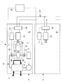
- FIG. 1 shows a partial configuration of the liquefied gas cooling device according to the first embodiment of the present invention
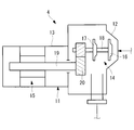
- FIG. 2 shows a schematic configuration of a compressor for a refrigeration system applied to the device. It is done.
- the liquefied gas cooling device 1 has a gas flow path 2 for flowing liquefied gas which is a raw material gas, and the gas flow path 2 is provided with a refrigeration system 3 for cooling the liquefied gas to a predetermined temperature. It is assumed.
- the refrigerating apparatus 3 adiabatically expands the compressor 4 for compressing the refrigerant, the condenser 5 for condensing and liquefying the high-temperature high-pressure refrigerant gas compressed by the compressor 4, and the refrigerant condensed by the condenser 5
- the refrigeration cycle 10 of the closed cycle is configured by connecting the throttling expander 6 to be operated and the evaporator 7 that evaporates the low-temperature low-pressure refrigerant adiabatically expanded by the throttling expander 6 by the refrigerant channel 9 in the above order. is there.
- Various expansion machines (expanders) or expansion valves can be used as the expansion / expansion unit 6 described above.
- the refrigeration apparatus 3 here is modularized as a small-capacity refrigeration apparatus 3 and a required cooling capacity (necessary cooling capacity) can be obtained by connecting a plurality of refrigeration modules A1, B1, C1,. It is configured as follows.
- the gas flow path 2 for flowing the natural gas to be liquefied is circulated to the downstream side process so as to be liquefied natural gas (LNG) at -162 ° C. by being sequentially cooled through the evaporator 7 of the refrigeration unit 3 It has become so.
- the gas flow path 2 may be connected in parallel or in series to the plurality of refrigeration modules A1, B1, C1.
- the compressor 4 applied to the refrigeration unit 3 is, as shown in FIG. 2, inside the housing 11 of a sealed structure configured by integrally connecting the compressor housing 12 and the motor housing 13 by bolts or the like.
- the compressor is a sealed electric compressor incorporating the compression mechanism 14 and the electric motor 15.
- the compressor 4 here has upper and lower two-stage impellers 16 and 17 and is driven through the speed increasing gear 20 by a motor shaft 19 rotatably supported at its rotating shaft 18 via a bearing (not shown). It is considered to be a type of turbo compressor that is designed to
- the compressor 4 is a two-stage compressor in which the impellers 16 and 17 are provided in upper and lower two stages, but may be a single-stage compressor or a multistage compressor having three or more stages. Thus, the compressor is driven via the speed increasing gear 20. However, it may be a compressor having a direct coupling structure in which the rotary shaft 18 and the motor shaft 19 are integrated.
- the electric motor 15 of the compressor 4 is integrally provided with power from a power source such as a generator to the grid interconnection converter 21, the power feeding circuit 22 and the respective refrigeration modules A1, B1 and C1 to form a modularized inverter 23 A power circuit for feeding power is connected.
- the grid interconnection converter 21 is modularized and multistaged corresponding to the multistage construction of the refrigeration system 3 (A1, B1, C1), and the inverter provided on the side of each of the refrigeration modules A1, B1, C1. And 23 are connected via a DC link.
- a cold heat source consisting of liquefied gas at -162 ° C. exists, so for example, using a superconducting cable or a superconducting motor It may be configured.
- a liquefied gas (LNG) is produced by cooling a raw material gas such as natural gas by the liquefied gas cooling device 1, by operating the refrigeration device 3 which is modularized into a plurality of units and arranged in multiple stages.
- the liquefied gas at normal temperature flowing in the gas flow path 2 is sequentially cooled by the evaporator 7, and is firstly predicted to about -30.degree. C., and then further cooled and subcooled therefrom to obtain -162.degree. It is called liquefied gas (LNG).
- the compressor 4 of each of the refrigeration modules A1, B1 and C1 operated in the process of liquefying and cooling the raw material gas has to carry out maintenance for replacing consumable parts such as bearings every preset operation time. It does not. At this time, after the compressor 4 is stopped and the refrigerant inside is recovered, maintenance is performed.
- the refrigeration apparatuses 3 are modularized as small-capacity units, and a plurality of refrigeration modules A1, B1 and C1 are connected in parallel or in series to the gas flow path 2. For this reason, when performing maintenance, it is sufficient to stop the operation sequentially and perform maintenance of the compressor 4 from the one where the operation time set in advance has elapsed, operate the other refrigeration modules, and stop the entire system. It is possible to maintain the compressor 4 individually while continuing the operation.
- the refrigeration system 3 is modularized, and a plurality of refrigeration modules A1, B1 and C1 are connected in parallel or in series to the gas flow path 2 so as to correspond to the required cooling capacity. Therefore, in the case of providing the liquefied gas cooling device 1 having the same capacity, one large-capacity refrigeration device is installed by installing a plurality of reduced-capacity refrigeration modules A1, B1, C1. Compared to the case, the degree of freedom of the arrangement of the devices can be enhanced. Therefore, while being able to relieve
- the compressor 4 is a hermetic compressor 4 of a type driven via an electric motor 15 built in a housing 11 of a hermetic structure together with a compression mechanism 14. Therefore, the shaft seal portion of the compressor drive shaft (rotational shaft) 18 can be eliminated, and the occurrence of a minute amount of refrigerant leakage due to the presence of the shaft seal portion can be eliminated. As a result, not only can maintenance for periodical replenishment of the refrigerant can be omitted but also maintenance costs, refrigerant costs for additional replenishment, and the like can be reduced.
- the compressor 4 is a compressor 4 of a type in which the electric motor 15 is built in the housing 11, it is not necessary to separately arrange devices for driving the compressor 4. Therefore, the installation space of the refrigeration system 3 can be reduced, and the restriction on the arrangement of the plant components can be eased, whereby the application to a plant with a narrow space can be facilitated.
- a power circuit connected to the electric motor 15 of the compressor 4 is modularized by integrally providing power from a power source such as a generator to the grid interconnection converter 21, the power feeding circuit 22 and the respective refrigeration modules A1, B1 and C1.
- the inverter 23 is composed of
- the grid interconnection converter 21 is modularized and multistaged corresponding to the multistage construction of the refrigeration system 3 (A1, B1, C1), and provided on the side of each of the refrigeration modules A1, B1, C1 It is configured to be connected to the corresponding inverter 23 via a DC link. Therefore, the connection with each of the refrigeration modules A1, B1, C1 can be facilitated.
- FIG. 1 a second embodiment of the present invention will be described using FIG.
- the present embodiment is configured such that a plurality of modularized compressors 4 are connected in parallel to the refrigeration cycle 10 with respect to the above-described first embodiment.
- the other points are the same as in the first embodiment, and thus the description thereof is omitted.
- the liquefied gas cooling device 1 modularizes the hermetic compressor 4 of a type in which the compression mechanism 14 and the electric motor 15 are built in the housing 11, and the compression module A 2,
- the refrigeration apparatus 3 has a configuration in which B2, C2, ... are connected in parallel between a plurality of suction channels 9A and a plurality of discharge channels 9B of the refrigeration cycle 10, and the refrigeration system 3 having this configuration is installed in the gas channel 2 It is
- Electric power from a power source such as a generator is supplied to the grid interconnection converter 21, the power feeding circuit 22, and each A power circuit is connected to be supplied with power via the inverter 23 which is modularized by being integrated with the compression modules A2, B2 and C2.
- the compressor 4 of the type incorporating the electric motor 15 is modularized, and a plurality of compression modules A2, B2, C2, ... are connected in parallel to the refrigeration cycle 10 so as to correspond to the necessary cooling capacity.
- a plurality of reduced-capacity compression modules A2, B2 and C2 can be connected in parallel to cope with the large capacity.
- the degree of freedom in the arrangement of the devices can be enhanced as compared with the case of installing one compressor of the above.
- the electric power circuit connected to the electric motor 15 of each compression module A2, B2, C2, ... is connected to the grid interconnection converter 21, the power supply circuit 22 and each compression module A2, B2, C2 And the inverter 23 modularized integrally.
- the grid interconnection converter 21 is connected to an inverter 23 provided on the side of each of the compression modules A2, B2 and C2 via a DC link. Therefore, the connection with each compression module A2, B2, C2 can be facilitated.
- FIG. 1 a third embodiment of the present invention will be described using FIG.
- the present embodiment is different from the above-described first embodiment in that a relay 24 is provided in the power supply circuit 22 to the compressor 4 of each of the refrigeration modules A1, B1 and C1.
- the other points are the same as in the first embodiment, and thus the description thereof is omitted.
- the relays 24 are respectively provided to the feeding circuits 22 of the inverters 23 for the electric motors 15 of the respective compressors 4 in the respective refrigeration modules A1, B1 and C1. It is provided. At the time of periodic maintenance of the compressor 4, the electric path of the compressor 4 is shut off by the relay 24 so that the power portion of the compressor stopped for maintenance can be maintained as an inactive line state.
- the relay 24 is provided in the power feeding circuit 22 to the inverter 23, and the relay 24 is provided in the suction flow passage 9A and the discharge flow passage 9B of the compressor 4 for maintenance on / off valves 25, 26. It is configured to turn on and off in response to the opening and closing of the.
- the on-off valves 25 and 26 are provided to the suction passage 9A and the discharge passage 9B of the compressor 4. It is sufficient to provide only the refrigerant in the compressor 4 by shutting off the refrigeration cycle 10 by the on-off valves 25 and 26. This makes it possible to facilitate maintenance and shorten its time.
- the operation time of the compressor 4 is counted by each controller 27 or the host controller 28, and the operation of the compressor 4 is stopped artificially or automatically when a preset operation time passes, and then the manual operation is performed manually.
- the maintenance on / off valves 25 and 26 are closed automatically.
- the refrigerant in the compressor 4 is recovered and maintenance is performed, in which case the power portion including the inverter 23 and the electric motor 15 remains in the active line state Since there is a risk of electric shock, when the relay 24 is turned off in response to the closing of the maintenance on / off valves 25 and 26, the electric power portion can be brought into the inactive line state.
- the maintenance of the compressor 4 is performed according to the following procedure. (1) The operation time of the compressor 4 is counted by each controller 27 or the host controller 28, and when a preset operation time has elapsed, it is determined that maintenance is necessary by alarming it via appropriate means. Operation of the refrigeration system 3 (compressor 4) is artificially or automatically stopped. (2) After the compressor 4 is stopped, the maintenance on-off valves 25 and 26 provided in the suction flow passage 9A and the discharge flow passage 9B are manually or automatically closed to shut off the refrigeration cycle 10 As a result, the compressor 4 is separated from the refrigeration cycle 10, the relay 24 is turned off, and the power portion of the compressor 4 is brought into the inactive line state.
- the controller 27 takes in a valve signal to the microcomputer and outputs the on / off signal to the relay 24 via the control program. It will be the method.
- a digital signal circuit system may be used in which the relay 24 is turned on / off via a relay circuit that operates based on a signal from an on / off switch attached to the on / off valves 25 and 26.
- a dual system may be provided to enhance the reliability.
- a protective lock or a control panel door which needs to be released at the time of maintenance may be used as an alternative means.
- an answerback signal output function is added to the relay 24 and there is a difference between the state of the on / off valves 25 and 26 for maintenance and the state of the relay 24, it is judged as an abnormal state, and the upper grid interconnection converter The system may be completely shut down with 21 turned off.
- the plurality of refrigeration modules A1, B1 and C1 are controlled in the number of operation as follows through the upper controller 28 It is supposed to be.
- the number of operating units is increased or decreased according to the required cooling capacity due to the increase or decrease of the flow rate of liquefied gas and the change of inflow temperature. Operation control is performed.
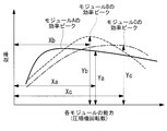
- the capacity range of each module can be adjusted by the inverter 23, and the efficiency when the number of operating modules of each module is reduced and the efficiency when the compressor rotational speed of each module is lowered to reduce the capacity
- the operation efficiency is higher, for example, if the operation efficiency is higher, it is determined and controlled so as to reduce the operation efficiency.
- the relationship between the capacity (compressor rotational speed) of each module and the efficiency is, for example, as shown in FIG. ⁇ (Xa * Ya) + (Xb * Yb) + (Xc * Yc) ⁇ Operation is controlled so as to maximize.
- the performance characteristic with respect to the rotational speed is preferably different.
- each module is optimized and operated with the module under maintenance excluded, and the maximum number of maintainable units determined from the capacity margin and resources of maintenance personnel The number and operating modules to be operated are determined so that maintenance time will be reached simultaneously.
- power from the power supply can be supplied to the electric motor 15 of the compressor 4 of each module via the grid interconnection converter 21 and the inverter 23, and the relay 24 is supplied to each of the power supply circuits 22. It is provided. For this reason, at the time of the periodic maintenance with respect to the compressor 4, the electric path to the said compressor 4 can be interrupted
- the relay 24 is configured to be turned on and off in response to opening and closing operations of maintenance on / off valves 25 and 26 provided on the suction side and the discharge side of the compressor 4. Therefore, when the regular maintenance time (operation time) for the compressor 4 elapses, the compressor 4 is artificially or automatically stopped, and the maintenance opening and closing provided on the suction side and the discharge side When the valves 25 and 26 are closed, the relay 24 is turned off in response to the operation, and the electric path to the compressor 4 can be shut off. Thus, when the compressor 4 is maintained, the power portion thereof can be reliably brought into the inactive line state, and the safety for the maintenance worker can be ensured more reliably.
- the maintenance on-off valves 25 and 26 are manually or automatically closed when the compressor 4 is stopped artificially or automatically after a preset operation time has elapsed. , 26 are detected to turn off the relay 24 and to shut off the electric path to the compressor 4, thereby making the compressor 4 in a state in which maintenance can be performed.
- the controller 27 or the host controller 28 counts the periodic maintenance time (operating time) of the compressor 4 and the compressor 4 is stopped, the maintenance on / off valves 25 and 26 are closed manually or automatically. Can be detected by the controller 27 or 28 or the like to turn off the relay 24. As a result, the electric path to the compressor 4 can be shut off, and the power portion can be deactivated and the compressor 4 can be maintained. Therefore, the regular maintenance of the compressor 4 and the process leading to the maintenance can be surely controlled, and the safety of the operator can be secured.
- the number of operating the refrigeration modules A1, B1, C1 or the compression modules A2, B2, C2 is increased or decreased according to the required cooling capacity due to the increase or decrease of the flow rate of liquefied gas and the change of inflow temperature. It is done. Therefore, it is necessary to cool the liquefied gas by operating the refrigeration modules A1, B1 and C1 or the compression modules A2, B2 and C2 according to the increase and decrease of the flow rate of the liquefied gas and the change of the inflow temperature. It is possible to provide just enough capacity as a cold energy. As a result, it is possible to save the excess power consumed for the cooling operation of the liquefied gas and perform the cooling operation without waste.
- the capacity of each module (A1, B1, C1 or A2, B2, C2) can be adjusted by the inverter 23, and the efficiency and compression when adjusting the capacity by increasing or decreasing the number of operating each module
- the efficiency is adjusted by increasing or decreasing the machine rotational speed to adjust the capacity, and adjustment is performed with the higher efficiency.
- the capacity range of the refrigeration modules A1, B1 and C1 or the compression modules A2, B2 and C2 is adjusted by the inverter 23, and the efficiency when the number of operating modules is reduced and the compressor rotational speed are reduced to reduce the capacity.
- the efficiency can be compared with that in the case of a reduction, and the operation can be performed with the ability adjusted with the higher efficiency.
- control is performed to reduce the number of operating units of each module (A1, B1, C1 or A2, B2, C2), thereby saving the power consumed for cooling operation as much as possible. can do.
- the refrigerating apparatus 3 which exchanges heat with the liquefied gas whose temperature changes largely due to sensible heat change greatly depends on the temperature range to be used, the performance characteristic with respect to the rotational speed is largely different. This makes it possible to maximally reduce the excess power consumed for the cooling operation.
- the maintenance cost per operation time of the compressor 4 is obtained by dividing the regular maintenance cost of the compressor 4 by the maintenance interval. Can be added to the power cost for comparison and judgment.
- the maintenance cost per operating time of the compressor 4 may be added to the electric power cost to compare and select it can.
- the refrigeration modules A1, B1 and C1 or the compression modules A2, B2 and C2 are optimized in the state where the modules under maintenance are excluded, and determined from the capacity margin and resources of maintenance personnel.
- the maximum number of vehicles that can be maintained simultaneously is decided to determine the number of modules to operate and the modules to be operated so that maintenance time will come simultaneously. Therefore, maintenance of each compressor can be performed by operating the system by controlling the number of modules and modules to be operated so that the maximum number of maintainable units determined from the capacity margin and resources of maintenance personnel simultaneously reach maintenance time. It is possible to carry out without stopping and without waiting for maintenance or increasing maintenance factors.
- the present invention is not limited to the invention according to the above-described embodiment, and appropriate modifications can be made without departing from the scope of the invention.
- the example which used the turbo compressor as compressor 4 applied to refrigeration unit 3 was explained in the above-mentioned embodiment, it is not limited to this, for example, screw compressor and reciprocating compression of other types A compressor such as a machine may be used.
- the liquefied gas cooling device 1 of the present invention can be similarly applied to the liquefaction of liquefied gas other than natural gas.
- all the refrigeration modules A1, B1 and C1 and the compressors 4 of the compression modules A2, B2 and C2 are inverter-driven compressors 4, but some of the compressors 4 are inverter-driven compressions.
- the machine or another compressor may be a constant speed compressor.
- the feed circuit 22 In this case, the power supply circuit 22 to the electric motor 15 is provided with the relay 24, and the electric path is interrupted by the relay 24 at the time of maintenance, and the electric power is supplied.
- the part may be in an inactivated radiation state.
- Cooling device for liquefied gas 2 Gas flow path 3
- Refrigeration device 4 Compressor 5
- Condenser 6 Throttling expander 7
- Evaporator 9 Refrigerant flow path 10
- Refrigeration flow path 11 Housing 14
- Compression mechanism 15 Electric motor 21
- Grid-connected converter 22 Feeding circuit 23
- Inverter 24 Relays 25 and 26 Maintenance valve 27
- Controller 28 Host controllers A1, B1 and C1 Refrigerating modules A2, B2 and C2 Compression module
Landscapes
- Engineering & Computer Science (AREA)
- Physics & Mathematics (AREA)
- Mechanical Engineering (AREA)
- Thermal Sciences (AREA)
- General Engineering & Computer Science (AREA)
- Chemical & Material Sciences (AREA)
- Chemical Kinetics & Catalysis (AREA)
- General Chemical & Material Sciences (AREA)
- Oil, Petroleum & Natural Gas (AREA)
- Separation By Low-Temperature Treatments (AREA)
- Control Of Positive-Displacement Pumps (AREA)
- Filling Or Discharging Of Gas Storage Vessels (AREA)
Priority Applications (6)
| Application Number | Priority Date | Filing Date | Title |
|---|---|---|---|
| EP15877061.0A EP3244138A4 (en) | 2015-01-05 | 2015-12-24 | Cooling device for liquefied gas |
| BR112017014138-8A BR112017014138A2 (pt) | 2015-01-05 | 2015-12-24 | aparelho de resfriamento de gás liquefeito |
| US15/538,094 US10571190B2 (en) | 2015-01-05 | 2015-12-24 | Liquefied gas cooling apparatus |
| MYPI2017702387A MY186879A (en) | 2015-01-05 | 2015-12-24 | Liquefied gas cooling apparatus |
| CN201580072172.2A CN107110574B (zh) | 2015-01-05 | 2015-12-24 | 液化气体用冷却装置 |
| KR1020177017159A KR101928229B1 (ko) | 2015-01-05 | 2015-12-24 | 액화 가스용 냉각 장치 |
Applications Claiming Priority (2)
| Application Number | Priority Date | Filing Date | Title |
|---|---|---|---|
| JP2015-000503 | 2015-01-05 | ||
| JP2015000503A JP6415989B2 (ja) | 2015-01-05 | 2015-01-05 | 液化ガス用冷却装置 |
Publications (1)
| Publication Number | Publication Date |
|---|---|
| WO2016111188A1 true WO2016111188A1 (ja) | 2016-07-14 |
Family
ID=56355887
Family Applications (1)
| Application Number | Title | Priority Date | Filing Date |
|---|---|---|---|
| PCT/JP2015/086134 Ceased WO2016111188A1 (ja) | 2015-01-05 | 2015-12-24 | 液化ガス用冷却装置 |
Country Status (8)
| Country | Link |
|---|---|
| US (1) | US10571190B2 (enExample) |
| EP (1) | EP3244138A4 (enExample) |
| JP (1) | JP6415989B2 (enExample) |
| KR (1) | KR101928229B1 (enExample) |
| CN (1) | CN107110574B (enExample) |
| BR (1) | BR112017014138A2 (enExample) |
| MY (1) | MY186879A (enExample) |
| WO (1) | WO2016111188A1 (enExample) |
Families Citing this family (7)
| Publication number | Priority date | Publication date | Assignee | Title |
|---|---|---|---|---|
| JP2016125773A (ja) * | 2015-01-05 | 2016-07-11 | 三菱重工業株式会社 | 液化ガス用冷却装置 |
| JP6320955B2 (ja) * | 2015-03-09 | 2018-05-09 | 株式会社神戸製鋼所 | 液化システム及び発電システム |
| CN110530058B (zh) * | 2018-05-20 | 2022-07-26 | 李华玉 | 联合循环热泵装置 |
| US20220090854A1 (en) * | 2020-09-18 | 2022-03-24 | L'air Liquide, Societe Anonyme Pour L'etude Et L?Exploitation Des Procedes Georges Claude | Process for subcooling liquid stream with refrigerant gas |
| JP2022170301A (ja) | 2021-04-28 | 2022-11-10 | 株式会社日立産機システム | 圧縮機 |
| JP7509252B1 (ja) * | 2023-02-24 | 2024-07-02 | いすゞ自動車株式会社 | 冷却構造 |
| US12535267B2 (en) | 2023-08-16 | 2026-01-27 | Air Products And Chemicals, Inc. | Apparatus and process for pre-liquefaction fluid processing for improved liquefaction operations |
Citations (9)
| Publication number | Priority date | Publication date | Assignee | Title |
|---|---|---|---|---|
| JPS51150757A (en) * | 1975-06-09 | 1976-12-24 | Inst Francais Du Petrole | Cooling system of liquid |
| JPS6129657A (ja) * | 1984-07-20 | 1986-02-10 | 株式会社東芝 | 冷凍装置 |
| JPS6424185A (en) * | 1987-07-15 | 1989-01-26 | Sanden Corp | Compressor actuation method |
| JP2001271753A (ja) * | 2000-03-29 | 2001-10-05 | Daikin Ind Ltd | 開放形圧縮機および開放形圧縮機ユニット |
| JP2008267722A (ja) * | 2007-04-23 | 2008-11-06 | Mitsubishi Electric Corp | 熱源機および冷凍空調装置 |
| JP2009027815A (ja) * | 2007-07-18 | 2009-02-05 | Fuji Heavy Ind Ltd | 系統連系コンバータ装置 |
| US20090232663A1 (en) * | 2008-03-13 | 2009-09-17 | Saul Mirsky | Compressor-Expander Set Critical Speed Avoidance |
| JP2012513005A (ja) * | 2008-11-25 | 2012-06-07 | テクニップ フランス | 天然ガス供給流を用いて過冷却された液化天然ガス流を生産するための工程、及び関連した装置 |
| JP2014066396A (ja) * | 2012-09-25 | 2014-04-17 | Ihi Corp | ターボ冷凍機 |
Family Cites Families (29)
| Publication number | Priority date | Publication date | Assignee | Title |
|---|---|---|---|---|
| US3413816A (en) | 1966-09-07 | 1968-12-03 | Phillips Petroleum Co | Liquefaction of natural gas |
| US3548606A (en) | 1968-07-08 | 1970-12-22 | Phillips Petroleum Co | Serial incremental refrigerant expansion for gas liquefaction |
| US3527059A (en) * | 1968-12-26 | 1970-09-08 | Phillips Petroleum Co | Method of controlling parallel-operating refrigeration compressors |
| JPS5952185A (ja) | 1982-09-20 | 1984-03-26 | 三菱重工業株式会社 | 間接式膨張タ−ビンサイクル再液化装置用主冷媒圧縮機 |
| US4698080A (en) | 1984-06-15 | 1987-10-06 | Phillips Petroleum Company | Feed control for cryogenic gas plant |
| JPH03160285A (ja) | 1989-11-17 | 1991-07-10 | Sanyo Electric Co Ltd | 冷凍装置 |
| JP3407441B2 (ja) | 1994-12-20 | 2003-05-19 | 松下電器産業株式会社 | 除湿機 |
| JPH10246526A (ja) | 1997-03-07 | 1998-09-14 | Hitachi Ltd | セパレート型空気調和装置 |
| JPH1183133A (ja) | 1997-09-01 | 1999-03-26 | Mitsubishi Heavy Ind Ltd | 空気調和機 |
| AU1937999A (en) | 1997-12-16 | 1999-07-05 | Lockheed Martin Idaho Technologies Company | Apparatus and process for the refrigeration, liquefaction and separation of gases with varying levels of purity |
| JP2002168545A (ja) | 2000-12-01 | 2002-06-14 | Mitsubishi Electric Corp | 冷凍サイクル装置 |
| US6647744B2 (en) | 2002-01-30 | 2003-11-18 | Exxonmobil Upstream Research Company | Processes and systems for liquefying natural gas |
| AU2003275396C1 (en) | 2002-09-30 | 2010-12-23 | Bp Corporation North America Inc. | Modular LNG process |
| EG24658A (en) | 2002-09-30 | 2010-04-07 | Bpcorporation North America In | All electric lng system and process |
| US6640586B1 (en) | 2002-11-01 | 2003-11-04 | Conocophillips Company | Motor driven compressor system for natural gas liquefaction |
| US6962060B2 (en) | 2003-12-10 | 2005-11-08 | Air Products And Chemicals, Inc. | Refrigeration compression system with multiple inlet streams |
| EP1856457B1 (en) | 2005-02-18 | 2017-07-12 | Carrier Corporation | Refrigeration circuit |
| US7665315B2 (en) * | 2005-10-21 | 2010-02-23 | Emerson Retail Services, Inc. | Proofing a refrigeration system operating state |
| JP4929350B2 (ja) | 2007-04-26 | 2012-05-09 | 株式会社日立製作所 | Lng製造設備と水製造設備とを組み合せた発電設備を有する複合プラント及びlng製造設備と水製造設備とを組み合せた発電設備を有する複合プラントの運転方法。 |
| EP2015011A1 (de) * | 2007-07-12 | 2009-01-14 | Siemens Aktiengesellschaft | Gasverflüssigungsanlage sowie ein Verfahren zum unterbrechungsfreien Betrieb einer Gasverflüssigungsanlage |
| US20090090131A1 (en) | 2007-10-09 | 2009-04-09 | Chevron U.S.A. Inc. | Process and system for removing total heat from base load liquefied natural gas facility |
| US20100281915A1 (en) | 2009-05-05 | 2010-11-11 | Air Products And Chemicals, Inc. | Pre-Cooled Liquefaction Process |
| JP5698912B2 (ja) | 2010-03-05 | 2015-04-08 | 株式会社日立産機システム | 圧縮機 |
| NL2005598C2 (en) * | 2010-10-29 | 2012-05-02 | Louis Zuurhout | Method and apparatus for cooling a hydrocarbon stream. |
| TWI646264B (zh) * | 2011-03-04 | 2019-01-01 | 美商布魯克機械公司 | 低溫冷凍系統以及用於控制氦氣冷凍劑之供給的方法 |
| FR2977015B1 (fr) | 2011-06-24 | 2015-07-03 | Saipem Sa | Procede de liquefaction de gaz naturel a triple circuit ferme de gaz refrigerant |
| JP2013061124A (ja) | 2011-09-14 | 2013-04-04 | Panasonic Corp | 冷却装置 |
| FR2983287B1 (fr) | 2011-11-25 | 2018-03-02 | L'air Liquide, Societe Anonyme Pour L'etude Et L'exploitation Des Procedes Georges Claude | Procede et installation de separation d'air par distillation cryogenique |
| AU2012216352B2 (en) * | 2012-08-22 | 2015-02-12 | Woodside Energy Technologies Pty Ltd | Modular LNG production facility |
-
2015
- 2015-01-05 JP JP2015000503A patent/JP6415989B2/ja active Active
- 2015-12-24 WO PCT/JP2015/086134 patent/WO2016111188A1/ja not_active Ceased
- 2015-12-24 CN CN201580072172.2A patent/CN107110574B/zh active Active
- 2015-12-24 MY MYPI2017702387A patent/MY186879A/en unknown
- 2015-12-24 BR BR112017014138-8A patent/BR112017014138A2/pt not_active Application Discontinuation
- 2015-12-24 US US15/538,094 patent/US10571190B2/en active Active
- 2015-12-24 EP EP15877061.0A patent/EP3244138A4/en not_active Withdrawn
- 2015-12-24 KR KR1020177017159A patent/KR101928229B1/ko active Active
Patent Citations (9)
| Publication number | Priority date | Publication date | Assignee | Title |
|---|---|---|---|---|
| JPS51150757A (en) * | 1975-06-09 | 1976-12-24 | Inst Francais Du Petrole | Cooling system of liquid |
| JPS6129657A (ja) * | 1984-07-20 | 1986-02-10 | 株式会社東芝 | 冷凍装置 |
| JPS6424185A (en) * | 1987-07-15 | 1989-01-26 | Sanden Corp | Compressor actuation method |
| JP2001271753A (ja) * | 2000-03-29 | 2001-10-05 | Daikin Ind Ltd | 開放形圧縮機および開放形圧縮機ユニット |
| JP2008267722A (ja) * | 2007-04-23 | 2008-11-06 | Mitsubishi Electric Corp | 熱源機および冷凍空調装置 |
| JP2009027815A (ja) * | 2007-07-18 | 2009-02-05 | Fuji Heavy Ind Ltd | 系統連系コンバータ装置 |
| US20090232663A1 (en) * | 2008-03-13 | 2009-09-17 | Saul Mirsky | Compressor-Expander Set Critical Speed Avoidance |
| JP2012513005A (ja) * | 2008-11-25 | 2012-06-07 | テクニップ フランス | 天然ガス供給流を用いて過冷却された液化天然ガス流を生産するための工程、及び関連した装置 |
| JP2014066396A (ja) * | 2012-09-25 | 2014-04-17 | Ihi Corp | ターボ冷凍機 |
Non-Patent Citations (1)
| Title |
|---|
| See also references of EP3244138A4 * |
Also Published As
| Publication number | Publication date |
|---|---|
| CN107110574A (zh) | 2017-08-29 |
| JP6415989B2 (ja) | 2018-10-31 |
| EP3244138A1 (en) | 2017-11-15 |
| KR101928229B1 (ko) | 2018-12-11 |
| US20170350649A1 (en) | 2017-12-07 |
| KR20170088392A (ko) | 2017-08-01 |
| BR112017014138A2 (pt) | 2018-01-02 |
| US10571190B2 (en) | 2020-02-25 |
| EP3244138A4 (en) | 2018-12-05 |
| CN107110574B (zh) | 2019-10-15 |
| JP2016125772A (ja) | 2016-07-11 |
| MY186879A (en) | 2021-08-26 |
Similar Documents
| Publication | Publication Date | Title |
|---|---|---|
| WO2016111188A1 (ja) | 液化ガス用冷却装置 | |
| WO2016111189A1 (ja) | 液化ガス用冷却装置 | |
| JP3680619B2 (ja) | 冷凍装置 | |
| EP2524144B1 (en) | Integral compressor-expander | |
| KR101727547B1 (ko) | 냉각기 코스트-스루를 위한 가변속 드라이브 제어 | |
| US20100186427A1 (en) | Exhaust system | |
| JP5984456B2 (ja) | 熱源システムの制御装置、熱源システムの制御方法、熱源システム、電力調整ネットワークシステム、及び熱源機の制御装置 | |
| KR101741708B1 (ko) | 컴프레서 장치 및 그 제어 방법 | |
| JP2016125772A5 (enExample) | ||
| CN108474371B (zh) | 双氦气压缩机 | |
| JP6556891B2 (ja) | 液化ガス用冷却装置およびそのメンテナンス方法 | |
| CN106969528B (zh) | 一种热量回收循环系统及其方法 | |
| US20220090854A1 (en) | Process for subcooling liquid stream with refrigerant gas | |
| TW202006251A (zh) | 低溫泵系統 | |
| JP2015194294A (ja) | 冷凍機 | |
| US20230417465A1 (en) | Refrigerator and operation method during precooling of refrigerator | |
| US10697457B2 (en) | Device for compressing and expanding a gas and method for controlling the pressure in two grids of a different nominal pressure level | |
| JP7362032B2 (ja) | 冷水製造システム | |
| JP7362031B2 (ja) | 冷水製造システム | |
| RU2701173C1 (ru) | Установка по выработке сжиженного природного газа | |
| JP4393211B2 (ja) | 空調冷凍装置及び空調冷凍装置の制御方法 | |
| CN119983584A (zh) | 基于同轴制冷机组的主备机在线切换系统及方法 | |
| JP5627947B2 (ja) | 空調・冷蔵・冷凍システム | |
| JP2022041737A (ja) | 圧縮機における圧縮気体冷却方法及び圧縮気体冷却装置 | |
| KR20150125782A (ko) | 터보냉동기의 압축기 운전제어방법 |
Legal Events
| Date | Code | Title | Description |
|---|---|---|---|
| 121 | Ep: the epo has been informed by wipo that ep was designated in this application |
Ref document number: 15877061 Country of ref document: EP Kind code of ref document: A1 |
|
| WWE | Wipo information: entry into national phase |
Ref document number: 15538094 Country of ref document: US |
|
| ENP | Entry into the national phase |
Ref document number: 20177017159 Country of ref document: KR Kind code of ref document: A |
|
| REEP | Request for entry into the european phase |
Ref document number: 2015877061 Country of ref document: EP |
|
| NENP | Non-entry into the national phase |
Ref country code: DE |
|
| REG | Reference to national code |
Ref country code: BR Ref legal event code: B01A Ref document number: 112017014138 Country of ref document: BR |
|
| ENP | Entry into the national phase |
Ref document number: 112017014138 Country of ref document: BR Kind code of ref document: A2 Effective date: 20170629 |