WO2016111185A1 - 電極およびそれを用いたリチウムイオン二次電池 - Google Patents
電極およびそれを用いたリチウムイオン二次電池 Download PDFInfo
- Publication number
- WO2016111185A1 WO2016111185A1 PCT/JP2015/086061 JP2015086061W WO2016111185A1 WO 2016111185 A1 WO2016111185 A1 WO 2016111185A1 JP 2015086061 W JP2015086061 W JP 2015086061W WO 2016111185 A1 WO2016111185 A1 WO 2016111185A1
- Authority
- WO
- WIPO (PCT)
- Prior art keywords
- oxide particles
- positive electrode
- negative electrode
- active material
- electrode
- Prior art date
- Legal status (The legal status is an assumption and is not a legal conclusion. Google has not performed a legal analysis and makes no representation as to the accuracy of the status listed.)
- Ceased
Links
Images

Classifications
-
- H—ELECTRICITY
- H01—ELECTRIC ELEMENTS
- H01M—PROCESSES OR MEANS, e.g. BATTERIES, FOR THE DIRECT CONVERSION OF CHEMICAL ENERGY INTO ELECTRICAL ENERGY
- H01M4/00—Electrodes
- H01M4/02—Electrodes composed of, or comprising, active material
- H01M4/13—Electrodes for accumulators with non-aqueous electrolyte, e.g. for lithium-accumulators; Processes of manufacture thereof
-
- H—ELECTRICITY
- H01—ELECTRIC ELEMENTS
- H01M—PROCESSES OR MEANS, e.g. BATTERIES, FOR THE DIRECT CONVERSION OF CHEMICAL ENERGY INTO ELECTRICAL ENERGY
- H01M10/00—Secondary cells; Manufacture thereof
- H01M10/05—Accumulators with non-aqueous electrolyte
- H01M10/052—Li-accumulators
-
- H—ELECTRICITY
- H01—ELECTRIC ELEMENTS
- H01M—PROCESSES OR MEANS, e.g. BATTERIES, FOR THE DIRECT CONVERSION OF CHEMICAL ENERGY INTO ELECTRICAL ENERGY
- H01M10/00—Secondary cells; Manufacture thereof
- H01M10/05—Accumulators with non-aqueous electrolyte
- H01M10/058—Construction or manufacture
- H01M10/0585—Construction or manufacture of accumulators having only flat construction elements, i.e. flat positive electrodes, flat negative electrodes and flat separators
-
- H—ELECTRICITY
- H01—ELECTRIC ELEMENTS
- H01M—PROCESSES OR MEANS, e.g. BATTERIES, FOR THE DIRECT CONVERSION OF CHEMICAL ENERGY INTO ELECTRICAL ENERGY
- H01M4/00—Electrodes
- H01M4/02—Electrodes composed of, or comprising, active material
- H01M4/62—Selection of inactive substances as ingredients for active masses, e.g. binders, fillers
-
- Y—GENERAL TAGGING OF NEW TECHNOLOGICAL DEVELOPMENTS; GENERAL TAGGING OF CROSS-SECTIONAL TECHNOLOGIES SPANNING OVER SEVERAL SECTIONS OF THE IPC; TECHNICAL SUBJECTS COVERED BY FORMER USPC CROSS-REFERENCE ART COLLECTIONS [XRACs] AND DIGESTS
- Y02—TECHNOLOGIES OR APPLICATIONS FOR MITIGATION OR ADAPTATION AGAINST CLIMATE CHANGE
- Y02E—REDUCTION OF GREENHOUSE GAS [GHG] EMISSIONS, RELATED TO ENERGY GENERATION, TRANSMISSION OR DISTRIBUTION
- Y02E60/00—Enabling technologies; Technologies with a potential or indirect contribution to GHG emissions mitigation
- Y02E60/10—Energy storage using batteries
-
- Y—GENERAL TAGGING OF NEW TECHNOLOGICAL DEVELOPMENTS; GENERAL TAGGING OF CROSS-SECTIONAL TECHNOLOGIES SPANNING OVER SEVERAL SECTIONS OF THE IPC; TECHNICAL SUBJECTS COVERED BY FORMER USPC CROSS-REFERENCE ART COLLECTIONS [XRACs] AND DIGESTS
- Y02—TECHNOLOGIES OR APPLICATIONS FOR MITIGATION OR ADAPTATION AGAINST CLIMATE CHANGE
- Y02P—CLIMATE CHANGE MITIGATION TECHNOLOGIES IN THE PRODUCTION OR PROCESSING OF GOODS
- Y02P70/00—Climate change mitigation technologies in the production process for final industrial or consumer products
- Y02P70/50—Manufacturing or production processes characterised by the final manufactured product
Definitions
- the present invention relates to an electrode and a lithium ion secondary battery using the electrode.
- Lithium ion batteries can be broadly classified into wound batteries and stacked batteries.
- the electrode element of the wound battery has a structure in which a positive electrode sheet and a negative electrode sheet are wound with a separator therebetween.
- the electrode element of the stacked battery has a structure in which a positive electrode sheet and a negative electrode sheet are separated by a separator and repeatedly stacked.
- the positive electrode sheet and the negative electrode sheet consist of an electrode application part in which a mixture comprising an active material, a binder and a conductive material is applied to a current collector, and an electrode that is not applied with a mixture to connect the electrode terminals. And an application part.
- the electrode element is enclosed in an outer case together with an electrolytic solution, a lithium-containing electrolyte, and the like.
- one end of the positive electrode terminal and the negative electrode terminal is electrically connected to the electrode uncoated part of the positive electrode and the electrode uncoated part of the negative electrode, respectively.
- the other end of the negative electrode terminal is drawn out of the outer case.
- the separator that separates the positive electrode and negative electrode of the battery is a porous film with a thickness of several tens to several hundreds of microns, so that during normal use, the electrolyte and lithium ions are passed through, but the positive electrode sheet and the negative electrode sheet are in direct contact with each other. There is nothing.
- the positive electrode and the negative electrode are short-circuited due to a metal foreign object or the like piercing the battery, the short-circuited portion generates heat, and the separator is greatly heat-shrinked in a direction parallel to the in-plane direction of the positive electrode or the negative electrode. May not be isolated. If the capacity is increased, the possibility of smoking, ignition, etc. is further increased.
- the amount of active material and electrolyte in the outer case increases, the amount of water contained in it increases. If moisture is present in the battery, the life of the battery may be shortened due to hydrogen and oxygen gas generation due to water electrolysis, such as expansion deformation of the outer case, leakage of the electrolyte, and cycle characteristics of the battery.
- Patent Document 1 As measures against moisture present in the battery, porous materials such as zeolite for absorbing moisture and alumina, silica, oxidation for neutralizing acid generated by the reaction between the lithium-containing electrolyte and moisture A proposal has been made to include an inorganic oxide as an acid neutralizing agent selected from magnesium in a battery element (Patent Document 2).
- the present invention suppresses the ignition and heat generation of the battery even when the positive electrode and the negative electrode are short-circuited by a metal foreign object or the like, and reduces gas generation by appropriately adsorbing moisture in the electrolyte.
- a lithium ion secondary battery that can be used.
- a lithium ion secondary battery in which a positive electrode in which a positive electrode active material layer is formed on a positive electrode current collector and a negative electrode in which a negative electrode active material layer is formed on a negative electrode current collector are alternately stacked via a separator, A protective layer containing oxide particles and a binder is formed on the active material layer surface of at least one of the positive electrode and the negative electrode, A lithium ion secondary battery characterized in that the water absorption rate of the protective layer under the following conditions is greater than 0 and 0.1% or less.
- the present invention since a protective layer containing oxide particles and a binder is formed on the surface of the electrode, even if the positive electrode and the negative electrode are short-circuited through the metal foreign object or the like, A protective layer remains between the electrodes around the foreign matter, and direct contact between the positive electrode surface and the negative electrode surface can be prevented. As a result, smoke and ignition of the battery can be suppressed.
- the protective layer since the protective layer has an appropriate water absorption rate, the hydrate derived from oxide particles generated in a very small amount enhances the adhesion with the electrode active material, and even if the separator shrinks, the active material It becomes easier to stay in the original position.
- generation of H 2 gas and O 2 gas is also suppressed by moisture adsorption, there is an effect of preventing the electrode element from these gases from being deformed.
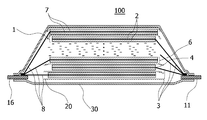
- FIG. 1 is a schematic view schematically showing a cross-sectional structure of a laminated battery 100 which is an embodiment of the lithium ion secondary battery of the present invention.
- the lithium ion secondary battery of the present invention includes an electrode laminate in which positive electrodes and negative electrodes are alternately stacked via separators, and a plurality of stacked or wound electrodes are provided.
- the electrode laminate is accommodated in a container together with the electrolytic solution, and a rectangular container formed of aluminum or a flexible film is used for the container.
- a positive electrode terminal and a negative electrode terminal are electrically connected to the electrode laminate, and a part or all of the positive electrode terminal and the negative electrode terminal are drawn out of the container.
- the positive electrode 1 is provided with an application part (positive electrode active material layer) 2 in which a slurry containing a positive electrode active material is applied and dried, and an uncoated part where no slurry is applied, on the front and back of the positive electrode current collector.
- an application part (negative electrode active material layer) 7 in which a slurry containing a negative electrode active material is applied and dried, and an uncoated part where no slurry is applied, on the front and back of the negative electrode current collector 8.
- the non-coated portion of the positive electrode active material in the positive electrode current collector is a positive electrode tab 3 for connecting to the positive electrode terminal 11
- the non-coated portion of the negative electrode active material in the negative electrode current collector is the negative electrode terminal.
- 16 is a negative electrode tab 8 for connection to 16.
- a protective layer capable of adsorbing moisture during the operation of the battery is formed on at least one of the surfaces where the positive electrode active material application part 2 and the negative electrode active material application part 7 face each other with the separator 20 therebetween.
- the positive electrode active material application part 2 and the negative electrode active material application part 7 are expressed regardless of whether or not a protective layer is formed on the surface of the active material layer of at least one of the positive electrode and the negative electrode. .
- FIG. 2 schematically shows an active material coating portion (active material layer) 14 formed on the current collector 13 provided with a protective layer 12 on the surface.
- the protective layer 12 is formed on both surfaces of the electrode.
- one or more protective layers may be provided between the opposing positive electrode and negative electrode, and may be provided on either the positive electrode or the negative electrode. That is, in one embodiment of the present invention, an active material layer formed on a current collector (metal foil), a protective layer containing oxide particles and a binder formed on the surface of the active material layer, An electrode comprising: a protective layer having a water absorption rate of greater than 0 and 0.1% or less under the following conditions is provided.
- the positive electrode tabs 3 are grouped on the positive electrode terminal 11 and connected to each other by ultrasonic welding or the like together with the positive electrode terminal 11, and the negative electrode tabs 8 are grouped on the negative electrode terminal 16 and connected to each other by ultrasonic welding or the like together with the negative electrode terminal 16. Is done.
- one end of the positive electrode terminal 11 is drawn out of the flexible film 30, and one end of the negative electrode terminal 16 is also drawn out of the flexible film 20.
- An insulating member for preventing a short circuit with the negative electrode terminal may be formed at the boundary portion 4 between the coated portion 2 and the uncoated portion of the positive electrode active material.
- the external dimensions of the negative electrode active material application part 7 are preferably larger than the external dimensions of the positive electrode active material application part 2 and smaller than the external dimensions of the separator 20.
- examples of the positive electrode active material include LiCoO 2 , LiNiO 2 , LiNi 1-x CoO 2 , LiNi x (CoAl) 1-x O 2 , LiNi 1/3 Co 1/3 Mn 1/3 O 2 , Layered oxide materials such as Li 2 MnO 3 —LiNi 1/3 Co 1/3 Mn 1/3 O 2 , spinel materials such as LiMn 2 O 4 , LiMn 1.5 Ni 0.5 O 4 , LiFePO olivine-based material such as 4, Li 2 CoPO 4 F, fluoride olivine-based material, such as Li 2 MnSiO 4 F, include, vanadium oxide-based material such as V 2 O 5, one or more of these Can be used as a mixture.
- a pH adjuster can be added to the slurry for positive electrode formation as a Mn ion elution prevention means.
- various acids can be added.
- oxalic acid which is a weak acid, particularly an organic acid.
- such a pH adjuster can be added to the electrolytic solution in addition to the positive electrode forming slurry.
- Examples of the negative electrode active material include carbon materials such as graphite, amorphous carbon, diamond-like carbon, fullerene, carbon nanotube, and carbon nanohorn, lithium metal materials, alloy materials such as silicon and tin, Nb 2 O 5 and TiO 2. These oxide-based materials or composites thereof can be used.
- the protective layer includes oxide particles and a binder.
- the oxide particles are not particularly limited, and any oxide particles can be used as long as they satisfy the absorptance described later and have insulating properties.
- the protective layer those in which oxide particles such as MgO, CaO, Al 2 O 3 , and SiO 2 are formed into a sheet shape with a binder are preferable, and MgO is particularly preferable.
- the binder for the protective layer polyvinylidene fluoride (PVdF), polytetrafluoroethylene (PTFE), carboxymethylcellulose (CMC), modified acrylonitrile rubber particles, etc. can be used.
- Ratio of binder to oxide particles Is 90 to 98% of oxide particles with respect to 2 to 10% of binder. If the binder is 2% or more, the oxide particles can be prevented from falling off the electrode surface. On the other hand, if the binder is 10% or less, a preferable water absorption rate can be secured.
- the water absorption rate of the protective layer is greater than 0 and 0.1% or less.
- the water absorption here is included in the coating layer at 85 ° C. of a sheet piece in which a slurry containing a binder for protective layer and oxide particles is applied to the surface of a metal foil that hardly absorbs water.
- oxide particles such as MgO subjected to surface treatment such as water resistance treatment are slurried together with a binder, and the slurry is applied to the surface of the active material layer of the electrode.
- the thickness of the protective layer is not particularly limited, but is preferably 0.2 ⁇ m or more and 20 ⁇ m or less, and more preferably 0.2 ⁇ m or more and 10 ⁇ m or less.
- Oxide particles with deliquescent properties such as MgO
- the adhesion between the oxide particles and the active material is not good, and instead it is necessary to use a large amount of a binder or the like. This is not preferable because the volume energy density is lowered.
- the ratio of MgO closed to the whole oxide particle shall be 50 mass% or more from a viewpoint of insulation and suppression of gas generation.
- the particle diameter of the oxide particles may be smaller than the thickness of the protective layer, but is preferably 0.1 ⁇ m or more and 10 ⁇ m or less, more preferably 0.1 or more and 1 ⁇ m or less. If it is 0.1 ⁇ m or more, the binder and the oxide particles do not aggregate. On the other hand, if the particle diameter is 10 ⁇ m or less, the thickness of the protective layer does not become too large.
- the pore volume of the oxide particles is preferably 0.3 cc / g or more from the viewpoint of holding the electrolytic solution.
- the oxide particles generate a trace amount of hydrate to enhance the adhesion between the protective layer and the active material layer, that is, preferably have an appropriate trace amount of deliquescence, other than MgO. These materials are also applicable.
- binder for the positive electrode active material and the negative electrode active material polyvinylidene fluoride (PVdF), polytetrafluoroethylene (PTFE), carboxymethyl cellulose (CMC), modified acrylonitrile rubber particles, and the like can be used.
- PVdF polyvinylidene fluoride
- PTFE polytetrafluoroethylene
- CMC carboxymethyl cellulose
- modified acrylonitrile rubber particles and the like
- the binder resin of the protective layer and the binder resin of the active material layer are preferably the same type of binder.
- a conductive support agent etc. can be added suitably to a positive electrode active material or a negative electrode active material, and 1 type, or 2 or more types, such as carbon black, carbon fiber, or graphite, can be combined as a conductive support agent.
- positive electrode current collector aluminum, stainless steel, nickel, titanium, or an alloy thereof can be used, and aluminum is particularly preferable.
- negative electrode current collector copper, stainless steel, nickel, titanium, or an alloy thereof can be used, and copper is particularly preferable.
- cyclic carbonates such as ethylene carbonate, propylene carbonate, vinylene carbonate, butylene carbonate, ethyl methyl carbonate (EMC), diethyl carbonate (DEC), dimethyl carbonate (DMC), dipropyl carbonate (DPC), etc.
- Organic solvents such as chain carbonates, aliphatic carboxylic acid esters, ⁇ -lactones such as ⁇ -butyrolactone, chain ethers, and cyclic ethers may be used singly or in combination. The lithium salt which dissolves in these organic solvents can be dissolved.
- these electrolytes may contain additives such as propane sultone, disulfonic acid ester, vinyl ethylene carbonate, vinylene carbonate, and the like that form an SEI film (Solid Electrolyte Interface) on the surface of the negative electrode and other flame retardants.
- additives such as propane sultone, disulfonic acid ester, vinyl ethylene carbonate, vinylene carbonate, and the like that form an SEI film (Solid Electrolyte Interface) on the surface of the negative electrode and other flame retardants.
- the separator examples include a resin porous film, a woven fabric, a non-woven fabric, and the like.
- a polyolefin resin such as polypropylene or polyethylene, a polyester resin, an acrylic resin, a styrene resin, or a nylon resin can be used as the resin component.
- a polyolefin-based microporous membrane is preferable because of its excellent ion permeability and physical separation between the positive electrode and the negative electrode.
- the separator may also be formed with a layer containing inorganic particles, and examples of the inorganic particles include insulating oxides, nitrides, sulfides, carbides, etc. Among them, TiO. 2 or Al 2 O 3 is preferably included.
- a flexible film, a can case, or the like can be used for the container, and it is preferable to use a flexible film from the viewpoint of reducing the weight of the battery.
- a laminate film in which a resin layer is provided on the front and back surfaces of a metal layer serving as a base material can be used.
- a metal layer having a barrier property such as preventing leakage of the electrolytic solution or entry of moisture from the outside can be selected, and aluminum, stainless steel, or the like can be used. Aluminum is particularly preferable.
- At least one surface of the metal layer is provided with a heat-fusible resin layer such as a modified polyolefin, and the heat-fusible resin layers of the flexible film are opposed to each other and around the portion for housing the electrode laminate Is heat-sealed to form an exterior body.
- a resin layer such as a nylon film or a polyester film can be provided on the surface of the exterior body that is the surface opposite to the surface on which the heat-fusible resin layer is formed.
- the positive electrode terminal can be made of aluminum or aluminum alloy, and the negative electrode terminal can be copper or copper alloy or nickel plated on them. Each terminal is pulled out to the outside of the flexible film. However, a heat-sealable resin can be provided in advance on each terminal at a position located at a portion where the periphery of the exterior body is thermally welded.
- Example 1 ⁇ Positive electrode> A mixed active material of LiMn 2 O 4 and Li (Ni 1/3 Co 1/3 Al 1/3 ) O 2 was used as the positive electrode active material, carbon black as the conductive agent, and PVdF as the binder 92: 4: A slurry in which these mixtures were dispersed in an organic solvent was prepared at a mass ratio of 4. This slurry was applied to a part of a current collector mainly composed of aluminum having a thickness of 20 ⁇ m and dried to form an application part of a positive electrode active material having a thickness of 80 ⁇ m. At this time, the portion of the current collector on which the slurry is not applied is used as an electrode tab. Next, a slurry in which PVdF and oxide particles were dispersed in an organic solvent was applied and dried on the surface of the positive electrode active material applied portion to form a protective layer.
- oxide particles those containing MgO, CaO, Al 2 O 3 and SiO 2 in a mass ratio of 98: 0.8: 0.1: 0.1 were used.
- MgO having an average particle diameter of 1 ⁇ m was used.
- PVdF as a binder was 15 wt% in a total of 100 wt% with oxide particles.
- the protective layer was formed to a thickness of 3 ⁇ m.
- An insulating tape was formed on the portion corresponding to the boundary between the coated portion and the uncoated portion of the positive electrode active material so as to cover both the coated portion and the uncoated portion. This insulating tape is for suppressing the fall off of the active material and the short circuit with the current collector.
- a prepared slurry was prepared. This slurry was intermittently applied to a 15 ⁇ m thick copper foil as a negative electrode current collector and dried so that the thickness after pressing was 55 ⁇ m on one side of the current collector. In this example, the step or inclination of the active material layer and the insulating member were not provided at the boundary between the negative electrode active material application part and the non-application part.
- the obtained positive electrode 20 layer and negative electrode 21 layer were laminated via a separator made of polypropylene having a thickness of 25 ⁇ m, and the negative electrode tab and the positive electrode tab, and the negative electrode terminal and the positive electrode terminal were ultrasonically welded, respectively.
- the film is mixed with ethylene carbonate (EC) and diethyl carbonate (DEC) at a ratio of 3: 7 and accommodated with a nonaqueous electrolytic solution to which LiPF 6 is added at 1 M / L, so that a laminated laminate as shown in FIG. A battery was obtained.
- EC ethylene carbonate
- DEC diethyl carbonate
- Example 2 The same conditions as in Example 1 except that MgO, CaO, Al 2 O 3 and SiO 2 were included as oxide particles of the protective layer in a mass ratio of 50: 30: 5: 10. A laminated battery was obtained.
- Example 1 A laminated laminate battery was obtained in the same manner as in Example 1 except that MgO not subjected to surface treatment was used for the oxide particles.
- Example 2 A laminated laminate battery was obtained in the same manner as in Example 1 except that the protective layer was not formed.
- the laminate battery of each of the examples and comparative examples was evaluated by averaging 10 pieces of each case for swelling and capacity reduction after the cycle characteristics of the laminated batteries of each example and comparative example.
- the thickness was small, and improvement in cycle characteristics was confirmed.
- a nail SUS304, ⁇ 3 mm was pierced into the laminated battery of each example and comparative example so as to penetrate the outer case, and the presence or absence of smoke or ignition was confirmed. The results are shown in Table 1.
- the present invention is useful for manufacturing an electrode of a lithium ion secondary battery and manufacturing a lithium ion secondary battery using the electrode.
Landscapes
- Chemical & Material Sciences (AREA)
- Chemical Kinetics & Catalysis (AREA)
- Electrochemistry (AREA)
- General Chemical & Material Sciences (AREA)
- Engineering & Computer Science (AREA)
- Manufacturing & Machinery (AREA)
- Materials Engineering (AREA)
- Battery Electrode And Active Subsutance (AREA)
- Secondary Cells (AREA)
- Connection Of Batteries Or Terminals (AREA)
Abstract
正極集電体に正極活物質層が形成された正極と、負極集電体に負極活物質層が形成された負極とが、セパレータを介して交互に積層されるリチウムイオン二次電池において、正極または負極の少なくとも一方の活物質層表面に酸化物粒子および結着剤を含む保護層が形成され、該保護層の下記条件での吸水率が0よりも大きく、0.1%以下であることを特徴とする。 <条件> 金属箔の表面に結着剤および酸化物粒子を含むスラリーを塗布し、シート片を85℃で塗工層中に含まれる溶媒が1000ppm以下になるまで乾燥させたときの乾燥前後の金属箔を除いた部分の質量の増加率。
Description
本発明は、電極および当該電極を用いたリチウムイオン二次電池に関する。
二次電池は、携帯電話、デジタルカメラ、ラップトップコンピュータなどのポータブル機器の電源としてはもちろん、車両等の電源としてとしても広く普及してきており、なかでも、高エネルギー密度で軽量なリチウムイオン電池は、生活に欠かせないエネルギー蓄積デバイスになっている。リチウムイオン電池は大別して捲回型電池と積層型電池に分類できる。捲回型電池の電極素子は正極シートと負極シートとをセパレータによって隔離して巻き回された構造を有する。積層型電池の電極素子は正極シートと負極シートとをセパレータによって隔離して繰り返し積層された構造を有する。正極シートおよび負極シートは、集電体に活物質、結着剤および導電材などからなる合剤が塗布された電極塗布部と、電極端子を接続するために合剤が塗布されていない電極未塗布部とを備えている。電極素子は、電解液やリチウム含有電解質等とともに外装ケースに封入されている。ここで、捲回型電池および積層型電池のいずれの電池素子にも、正極端子と負極端子の一端がそれぞれ正極の電極未塗布部と負極の電極未塗布部に電気的に接続され、正極端子と負極端子の他端が外装ケースの外部に引き出されている。
このような高エネルギー密度のリチウムイオン二次電池は、さらなる高エネルギー密度と大容量化が期待されており、同時に安全性の確保がますます重要になっている。
電池の正極と負極とを隔離するセパレータは多孔膜で数十~数百ミクロンの厚さを持っているため、通常使用時には電解液およびリチウムイオンを通すものの、正極シートと負極シートとが直接触れることはない。しかし、電池に金属異物等が突き刺さるなどして正極と負極が短絡すると、短絡部分は発熱し、セパレータが正極や負極の面内方向と平行な方向にも大きく熱収縮してしまい、正極と負極を隔離することができなくなるおそれがある。大容量化されれば発煙、発火等に至る可能性が一層高くなる。
電池の正極と負極とを隔離するセパレータは多孔膜で数十~数百ミクロンの厚さを持っているため、通常使用時には電解液およびリチウムイオンを通すものの、正極シートと負極シートとが直接触れることはない。しかし、電池に金属異物等が突き刺さるなどして正極と負極が短絡すると、短絡部分は発熱し、セパレータが正極や負極の面内方向と平行な方向にも大きく熱収縮してしまい、正極と負極を隔離することができなくなるおそれがある。大容量化されれば発煙、発火等に至る可能性が一層高くなる。
また、外装ケース内の活物質や電解液の量が増えると、それに含まれる水分量も多くなる。電池内に水分が存在すると、水の電気分解による水素や酸素のガス発生により外装ケースの膨張変形、電解液の漏れ、さらには電池としてのサイクル特性等、寿命を低下させることがある。
金属異物等の突き刺さりに対する安全対策としては、ポリオレフィン系のセパレータ膜基材と、当該基材の表面等にバインダー高分子により無機物粒子同士を結び付けて気孔構造を持たせた活性層を含ませたセパレータが提案されている(特許文献1)。
また、電池中に存在する水分に対する対策としては、水分を吸収するためのゼオライト等の多孔性物質と、リチウム含有電解質と水分との反応で生じた酸を中和するためのアルミナ、シリカ、酸化マグネシウムから選択される酸中和剤としての無機酸化物と、を電池素子中に含ませる提案がされている(特許文献2)。
また、電池中に存在する水分に対する対策としては、水分を吸収するためのゼオライト等の多孔性物質と、リチウム含有電解質と水分との反応で生じた酸を中和するためのアルミナ、シリカ、酸化マグネシウムから選択される酸中和剤としての無機酸化物と、を電池素子中に含ませる提案がされている(特許文献2)。
特許文献1や特許文献2に記載されているような無機物を電極活物質やセパレータに含ませると、当該無機物が存在する分だけ電解液や電極活物質が存在できる領域が減り、体積あたりのエネルギー密度の低下を招くことがある。一方、無機物の量を減らすと正極と負極の短絡を防ぐことが難しくなるという課題がある。またゼオライトは細孔等を調整することにより水分を選択的に吸着しようとすると、電解液を保液することやリチウムイオンの挿入放出の妨げとなることがあった。
そこで本発明は、金属異物等が突き刺さることなどによって生じる正極と負極との短絡時にも、電池の発火や発熱を抑制するとともに、電解液中の水分を適切に吸着することでガスの発生を低減することが可能なリチウムイオン二次電池を提供する。
すなわち、本発明の実施形態によれば、
正極集電体に正極活物質層が形成された正極と、負極集電体に負極活物質層が形成された負極とが、セパレータを介して交互に積層されるリチウムイオン二次電池において、
前記正極または負極の少なくとも一方の活物質層表面に酸化物粒子および結着剤を含む保護層が形成され、
該保護層の下記条件での吸水率が0よりも大きく、0.1%以下であることを特徴とするリチウムイオン二次電池が提供される。
<条件>
集電体の表面に結着剤および酸化物粒子を含むスラリーを塗布し、シート片を85℃で電極中に含まれる溶媒が1000ppm以下になるまで乾燥させたときの乾燥前後の集電体を除いた部分の質量の増加率。
正極集電体に正極活物質層が形成された正極と、負極集電体に負極活物質層が形成された負極とが、セパレータを介して交互に積層されるリチウムイオン二次電池において、
前記正極または負極の少なくとも一方の活物質層表面に酸化物粒子および結着剤を含む保護層が形成され、
該保護層の下記条件での吸水率が0よりも大きく、0.1%以下であることを特徴とするリチウムイオン二次電池が提供される。
<条件>
集電体の表面に結着剤および酸化物粒子を含むスラリーを塗布し、シート片を85℃で電極中に含まれる溶媒が1000ppm以下になるまで乾燥させたときの乾燥前後の集電体を除いた部分の質量の増加率。
本発明によれば、電極の表面に酸化物粒子及び結着剤を含む保護層を形成しているため、金属異物等が突き刺さることなどによって正極と負極とがそれを介して短絡したとしても、異物周辺の電極間に保護層が残り、正極電極表面と負極電極表面とが直接接触することを防ぐことができる。その結果、電池の発煙や発火を抑制することができる。また、保護層が適度な吸水率を有することで、ごく微量に発生する酸化物粒子由来の水和物が電極活物質との密着性を高め、セパレータ等が収縮しても活物質に対して元の位置にとどまりやすくなる。加えて、水分の吸着によってH2ガスやO2ガスの発生も抑制するため、これらのガスによる電極素子が変形を防ぐ効果がある。
以下、本発明の実施形態について図面を用いて説明する。
図1は本発明のリチウムイオン二次電池の一形態であるラミネート電池100の一断面構造を模式的に示した概略図である。
図1は本発明のリチウムイオン二次電池の一形態であるラミネート電池100の一断面構造を模式的に示した概略図である。
本発明のリチウムイオン二次電池は、正極と負極とがセパレータを介して交互に重ねられ、複数積層または捲回された電極積層体を備えている。
電極積層体は電解液と共に容器に収容され、容器にはアルミニウムで成型された角型容器や、可撓性フィルムが用いられる。前記電極積層体には正極端子および負極端子が電気的に接続されており、前記正極端子および前記負極端子の一部または全部が容器の外部に引き出されている構成になっている。
電極積層体は電解液と共に容器に収容され、容器にはアルミニウムで成型された角型容器や、可撓性フィルムが用いられる。前記電極積層体には正極端子および負極端子が電気的に接続されており、前記正極端子および前記負極端子の一部または全部が容器の外部に引き出されている構成になっている。
正極1には正極集電体の表裏に、正極活物質を含むスラリーを塗布し乾燥した塗布部(正極活物質層)2とスラリーが塗布されない未塗布部がそれぞれ設けられており、負極6には負極集電体8の表裏に、負極活物質を含むスラリーを塗布し乾燥した塗布部(負極活物質層)7とスラリーが塗布されない未塗布部がそれぞれ設けられている。
図1に示すラミネート電池100では、正極集電体における正極活物質の未塗布部を正極端子11と接続するための正極タブ3とし、負極集電体における負極活物質の未塗布部は負極端子16と接続するための負極タブ8とする。正極活物質の塗布部2と負極活物質の塗布部7とがセパレータ20を介して対向する面の少なくとも一方には、電池の動作中に水分を吸着可能な保護層が形成されている。本発明では正極と負極の少なくとも一方の電極の活物質層表面に保護層が形成されているか否かに関わらず、正極活物質の塗布部2および負極活物質の塗布部7と表現している。
なお、図2は集電体13に形成された活物質の塗布部(活物質層)14表面に保護層12を設けたものを模式的に示したものである。図2では電極の両面に保護層12を形成しているが、対向する正極と負極との間に1層以上保護層があればよく、正極及び負極のいずれか一方側に設けてもよい。つまり、本発明の一実施形態例では、集電体(金属箔)上に形成された活物質層と、該活物質層表面に形成された、酸化物粒子および結着剤を含む保護層とを備えた電極であって、該保護層の下記条件での吸水率が0よりも大きく、0.1%以下であることを特徴とする電極が提供される。
<条件>
金属箔の表面に結着剤および酸化物粒子を含むスラリーを塗布し、シート片を85℃で塗工層中に含まれる溶媒が1000ppm以下になるまで乾燥させたときの乾燥前後の金属箔を除いた部分の質量の増加率。
<条件>
金属箔の表面に結着剤および酸化物粒子を含むスラリーを塗布し、シート片を85℃で塗工層中に含まれる溶媒が1000ppm以下になるまで乾燥させたときの乾燥前後の金属箔を除いた部分の質量の増加率。
正極タブ3同士は正極端子11上にまとめられ、正極端子11とともに超音波溶接等で互いに接続され、負極タブ8同士は負極端子16上にまとめられ、負極端子16とともに超音波溶接等で互いに接続される。そのうえで、正極端子11の一端は可撓性フィルム30の外部に引き出され、負極端子16の一端も可撓性フィルム20の外部に引き出されている。
正極活物質の塗布部2と未塗布部の境界部4には、負極端子との短絡を防止するための絶縁部材を形成してもよい。
なお、負極活物質の塗布部7の外形寸法は正極活物質の塗布部2の外形寸法よりも大きく、セパレータ20の外形寸法よりも小さいことが好ましい。
なお、負極活物質の塗布部7の外形寸法は正極活物質の塗布部2の外形寸法よりも大きく、セパレータ20の外形寸法よりも小さいことが好ましい。
ラミネート電池において、正極活物質としては、例えばLiCoO2、LiNiO2、LiNi1-xCoO2、LiNix(CoAl)1-xO2、LiNi1/3Co1/3Mn1/3O2、Li2MnO3-LiNi1/3Co1/3Mn1/3O2などの層状酸化物系材料や、LiMn2O4、LiMn1.5Ni0.5O4などのスピネル系材料、LiFePO4などのオリビン系材料、Li2CoPO4F、Li2MnSiO4Fなどのフッ化オリビン系材料、V2O5などの酸化バナジウム系材料などが挙げられ、これらの1種または2種以上を混合して使用することができる。
なお、正極活物質としてLiMn系複合酸化物を使用する場合、保護層に使用する酸化物粒子がアルカリ性を呈すると、Mnイオンの溶出が起こり易くなり、電池特性が低下することがある。このため、Mnイオン溶出防止手段として、pH調整剤を正極形成用スラリー中に添加することができる。pH調整剤としては、各種酸類を添加することができるが、酸性が強すぎると、正極活物質や後述する保護層の酸化物粒子への悪影響が懸念される。本発明では、弱酸、特に有機酸であるシュウ酸を用いることが好ましい。また、このようなpH調整剤は、正極形成用スラリー中に添加する以外に、電解液中に添加することもできる。
負極活物質としては黒鉛、非晶質炭素、ダイヤモンド状炭素、フラーレン、カーボンナノチューブ、カーボンナノホーンなどの炭素材料や、リチウム金属材料、シリコンやスズなどの合金系材料、Nb2O5やTiO2などの酸化物系材料、あるいはこれらの複合物を用いることができる。
保護層は、酸化物粒子および結着剤を含む。酸化物粒子としては、特に制限はないが、後述する吸収率を満足するもので、絶縁性を有するものであればいずれも使用することができる。保護層としては、MgO、CaO、Al2O3、SiO2等の酸化物粒子を結着剤によってシート状に形成されたものが好ましく、特にMgOを含むことが好ましい。保護層の結着剤としてはポリフッ化ビニリデン(PVdF)、ポリテトラフルオロエチレン(PTFE)、カルボキシメチルセルロース(CMC)、変性アクリロニトリルゴム粒子などを用いることができる、結着剤と酸化物粒子との比率は質量比で結着剤2~10%に対して酸化物粒子が90~98%である。結着剤が2%以上であれば、酸化物粒子が電極表面から脱落することを抑制できる。一方、結着剤が10%以下であれば、好ましい吸水率を確保することができる。
保護層の吸水率は0よりも大きく、0.1%以下である。なお、ここでの吸水率は、実質的に殆ど吸水しない金属箔の表面に保護層用の結着剤および酸化物粒子を含むスラリーを塗布したシート片を85℃で塗工層中に含まれる溶媒が1000ppm以下になるまで乾燥させたときの乾燥前後の金属箔を除いた部分の質量の増加率としている。このような吸水率の保護層を得るためには、耐水処理などの表面処理がなされたMgOなどの酸化物粒子を結着剤とともにスラリー化し、そのスラリーを電極の活物質層表面に塗布し、十分に乾燥して、実質的に結着剤および酸化粒子でシート化することで得ることができる。特に潮解性の高いMgOを使用する場合、表面処理して使用することが好ましい。この表面処理は任意の方法を選択すればよく、たとえばMgO粒子とともに、CaO、Al2O3、SiO2のうちの少なくとも1種を含む混合物を熱処理し、MgO粒子の周囲にCaO、Al2O3、SiO2のうちの少なくとも1種を付着させて複合粒子とすればよい。
保護層の厚みは、特に限定されるものではないが、0.2μm以上20μm以下であることが好ましく、0.2μm以上10μm以下であることより好ましい。
保護層の厚みは、特に限定されるものではないが、0.2μm以上20μm以下であることが好ましく、0.2μm以上10μm以下であることより好ましい。
MgOなどの潮解性のある酸化物粒子は、表面処理をしないと、吸水性および潮解性が高くなり過ぎて水和物が酸化物粒子の表面にとどまらずに電解液中にも拡散しやすくなり、電解液を変質させる可能性やリチウムイオンの移動を阻害する可能性が高くなるため好ましくない。一方、まったく潮解と固化を生じない粒子を用いた場合には、酸化物粒子と活物質との密着性は良好にならず、その代わりに結着剤等を多く用いる必要があり、電池としての体積エネルギー密度を低下させるため好ましくない。酸化物粒子全体に閉めるMgOの割合は絶縁性及びガス発生の抑制の観点から50質量%以上とすることが好ましい。
酸化物粒子の粒子径としては保護層の厚みよりも小さければよいが、0.1μm以上10μm以下が好ましく、より好ましくは0.1以上1μm以下である。0.1μm以上であれば、結着剤と酸化物粒子とが凝集することなく、一方、粒子径が10μm以下であれば、保護層の厚みが大きくなりすぎることがない。酸化物粒子の細孔容積は電解液を保持する観点から0.3cc/g以上あるのが好ましい。
本発明において、酸化物粒子は微量な水和物を生成して保護層と活物質層との密着性を高めることが重要であり、すなわち適切な微量の潮解性を有することが好ましく、MgO以外の材料も応用可能である。
正極活物質、負極活物質の結着剤としてはポリフッ化ビニリデン(PVdF)、ポリテトラフルオロエチレン(PTFE)、カルボキシメチルセルロース(CMC)、変性アクリロニトリルゴム粒子などを用いることができる。活物質層上に保護層を形成する場合、保護層の結着樹脂と活物質層の結着樹脂が同種の結着剤であることが好ましい。また、正極活物質や負極活物質には導電助剤等を適宜加えることができ、導電助剤としては、カーボンブラック、炭素繊維または黒鉛などの1種または2種以上を組み合わせることができる。
正極集電体としてはアルミニウム、ステンレス鋼、ニッケル、チタンまたはこれらの合金等を用いることができ、特にアルミニウムが好ましい。負極集電体としては銅、ステンレス鋼、ニッケル、チタンまたはこれらの合金を用いることができ、特に銅が好ましい。
また、電解液としては、エチレンカーボネート、プロピレンカーボネート、ビニレンカーボネート、ブチレンカーボネート等の環状カーボネート類、エチルメチルカーボネート(EMC)、ジエチルカーボネート(DEC)、ジメチルカーボネート(DMC)、ジプロピルカーボネート(DPC)等の鎖状カーボネート類、脂肪族カルボン酸エステル類、γ-ブチロラクトン等のγ-ラクトン類、鎖状エーテル類、環状エーテル類、などの有機溶媒を一種又は二種以上を混合して使用することができ、これらの有機溶媒に溶解するリチウム塩を溶解させる。また、これらの電解液にはプロパンスルトン、ジスルホン酸エステル、ビニルエチレンカーボネート、ビニレンカーボネート等、負極の表面にSEI膜(Solid Electrolyte Interface)を形成する添加剤や、その他難燃剤を含ませることができる。
セパレータとしては、樹脂製の多孔膜、織布、不織布等があげられ、例えば樹脂成分としてはポリプロピレンやポリエチレン等のポリオレフィン樹脂、ポリエステル樹脂、アクリル樹脂、スチレン樹脂またはナイロン樹脂等を用いることができる。特にポリオレフィン系の微多孔膜は、イオン透過性および正極と負極との物理的な隔離性に優れているため好ましい。また、必要に応じて、セパレータにも無機物粒子を含む層を形成してもよく、無機物粒子としては、絶縁性の酸化物、窒化物、硫化物、炭化物などを挙げることができ、なかでもTiO2やAl2O3を含むことが好ましい。
容器には可撓性フィルムや缶ケース等を用いることができ、電池の軽量化の観点からは可撓性フィルムを用いることが好ましい。可撓性フィルムは、基材となる金属層の表裏面に樹脂層が設けられたラミネートフィルムを用いることができる。金属層には電解液の漏出や外部からの水分の侵入を防止する等のバリア性を有するものを選択することができ、アルミニウム、ステンレス鋼などを用いることができるが、アルミニウムが特に好ましい。金属層の少なくとも一方の面には変性ポリオレフィンなどの熱融着性の樹脂層が設けられ、可撓性フィルムの熱融着性の樹脂層同士を対向させ、電極積層体を収納する部分の周囲を熱融着することで外装体を形成する。熱融着性の樹脂層が形成された面と反対側の面となる外装体表面にはナイロンフィルム、ポリエステルフィルムなどの樹脂層を設けることができる。
正極端子には、アルミニウムやアルミニウム合金で構成されたもの、負極端子には銅や銅合金あるいはそれらにニッケルメッキを施したものなどを用いることができる。それぞれの端子は可撓性フィルムの外部に引き出されるが、外装体の周囲を熱溶着する部分に位置する箇所には、それぞれの端子にも熱融着性の樹脂をあらかじめ設けることができる。
以下、実施例を参照して本発明を具体的に説明するが、本発明はこれらの実施例のみに限定されるものではない。
(実施例1)
<正極>
正極活物質としてLiMn2O4とLi(Ni1/3Co1/3Al1/3)O2との混合活物質を用い、導電剤としてカーボンブラック、結着剤としてPVdFを92:4:4の質量比で用い、これらの合剤を有機溶媒中に分散したスラリーを準備した。このスラリーを、厚み20μmのアルミニウムを主成分とする集電体の一部に塗布、乾燥し、厚さ80μmの正極活物質の塗布部を形成した。このとき、スラリーを塗布しなかった集電体の部分を電極タブとして利用する。次に、この正極活物質の塗布部表面に、有機溶媒中にPVdFおよび酸化物粒子を分散したスラリーを塗布乾燥し、保護層を形成した。
<正極>
正極活物質としてLiMn2O4とLi(Ni1/3Co1/3Al1/3)O2との混合活物質を用い、導電剤としてカーボンブラック、結着剤としてPVdFを92:4:4の質量比で用い、これらの合剤を有機溶媒中に分散したスラリーを準備した。このスラリーを、厚み20μmのアルミニウムを主成分とする集電体の一部に塗布、乾燥し、厚さ80μmの正極活物質の塗布部を形成した。このとき、スラリーを塗布しなかった集電体の部分を電極タブとして利用する。次に、この正極活物質の塗布部表面に、有機溶媒中にPVdFおよび酸化物粒子を分散したスラリーを塗布乾燥し、保護層を形成した。
酸化物粒子には、MgOとCaOとAl2O3とSiO2が質量比で98:0.8:0.1:0.1の比率で含まれるものを用いた。MgOは平均粒子径が1μmのものを使用した。また、結着剤としてのPVdFは、酸化物粒子との合計100wt%中、15wt%とした。保護層は3μmの厚みに形成した。
正極活物質の塗布部と未塗布部との境界にあたる部分には、塗布部と未塗布部のどちらにもかかるように絶縁テープを形成した。この絶縁テープは活物質の脱落および集電体との短絡を抑制するためのものである。
<負極>
負極活物質として表面を非晶質炭素で被覆した黒鉛を用い、結着剤としてPVdFを用い(黒鉛:結着剤=95;5(質量比))、これらの合剤を有機溶媒中に分散したスラリーを準備した。このスラリーを、負極集電体である厚み15μmの銅箔に間欠的に塗布・乾燥し、プレス後の厚みが集電体の片面で55μmとなるようにした。本実施例では負極活物質の塗布部と未塗布部の境界に活物質層の段差や傾斜および絶縁部材は設けなかった。
負極活物質として表面を非晶質炭素で被覆した黒鉛を用い、結着剤としてPVdFを用い(黒鉛:結着剤=95;5(質量比))、これらの合剤を有機溶媒中に分散したスラリーを準備した。このスラリーを、負極集電体である厚み15μmの銅箔に間欠的に塗布・乾燥し、プレス後の厚みが集電体の片面で55μmとなるようにした。本実施例では負極活物質の塗布部と未塗布部の境界に活物質層の段差や傾斜および絶縁部材は設けなかった。
<ラミネート電池の作製>
得られた正極20層と負極21層とを厚み25μmのポリプロピレンからなるセパレータを介して積層し、これらの負極タブ及び正極タブと負極端子及び正極端子とをそれぞれ超音波溶接し、可撓性のフィルムに、エチレンカーボネート(EC)とジエチルカーボネート(DEC)を3:7で混合し、LiPF6を1M/L添加した非水電解液とともに収容することで、図1に示すような積層型のラミネート電池を得た。
得られた正極20層と負極21層とを厚み25μmのポリプロピレンからなるセパレータを介して積層し、これらの負極タブ及び正極タブと負極端子及び正極端子とをそれぞれ超音波溶接し、可撓性のフィルムに、エチレンカーボネート(EC)とジエチルカーボネート(DEC)を3:7で混合し、LiPF6を1M/L添加した非水電解液とともに収容することで、図1に示すような積層型のラミネート電池を得た。
(実施例2)
保護層の酸化物粒子としてMgOとCaOとAl2O3とSiO2とを質量比で50:30:5:10の比率で含ませた以外の条件は実施例1と同様にして積層型のラミネート電池を得た。
保護層の酸化物粒子としてMgOとCaOとAl2O3とSiO2とを質量比で50:30:5:10の比率で含ませた以外の条件は実施例1と同様にして積層型のラミネート電池を得た。
(比較例1)
酸化物粒子に表面処理がされていないMgOを用いた以外の条件は実施例1と同様にして積層型のラミネート電池を得た。
酸化物粒子に表面処理がされていないMgOを用いた以外の条件は実施例1と同様にして積層型のラミネート電池を得た。
(比較例2)
保護層を形成しない以外の条件は実施例1と同様にして積層型のラミネート電池を得た。
保護層を形成しない以外の条件は実施例1と同様にして積層型のラミネート電池を得た。
<評価>
実施例1,2及び比較例1の保護層用スラリーをAl箔の表面に塗布したシート片を85℃で保護層中に含まれる溶媒が1000ppm以下になるまで乾燥させたときの乾燥前後のAl箔を除いた部分の質量の増加率を吸水率(%)として評価した。
実施例1,2及び比較例1の保護層用スラリーをAl箔の表面に塗布したシート片を85℃で保護層中に含まれる溶媒が1000ppm以下になるまで乾燥させたときの乾燥前後のAl箔を除いた部分の質量の増加率を吸水率(%)として評価した。
また、各実施例および比較例のラミネート電池のサイクル特性後の外装ケースの膨れ、容量の低下を各水準ともに10ピースずつ評価して平均したところ、実施例1~2のラミネート電池は比較例1に対して厚みが小さく、サイクル特性の改善が確認された。
また、各実施例および比較例のラミネート電池に釘(SUS304、φ3mm)を外装ケースを貫通するように突き刺し、発煙や発火の有無を確認した。
以上の結果を表1に示す。
また、各実施例および比較例のラミネート電池に釘(SUS304、φ3mm)を外装ケースを貫通するように突き刺し、発煙や発火の有無を確認した。
以上の結果を表1に示す。

表1に示すように、保護層を設けることで電池内の水分が酸化物粒子に吸収され、ガス発生が抑制されていることが分かる。さらに、保護層の吸水率が0を超え、0.1%以下であることで、釘刺し試験における発煙や発火が防止できることが確認された。
以上、実施例を参照して本願発明を説明したが、本願発明は上記実施例に限定されものではない。本願発明の構成や詳細には、本願発明のスコープ内で当業者が理解し得る様々な変更をすることができる。
以上、実施例を参照して本願発明を説明したが、本願発明は上記実施例に限定されものではない。本願発明の構成や詳細には、本願発明のスコープ内で当業者が理解し得る様々な変更をすることができる。
本発明は、リチウムイオン二次電池の電極の製造および当該電極を用いたリチウムイオン二次電池の製造に有用である。
この出願は、2015年1月5日に出願された日本出願特願2015-59を基礎とする優先権を主張し、その開示の全てをここに取り込む。
この出願は、2015年1月5日に出願された日本出願特願2015-59を基礎とする優先権を主張し、その開示の全てをここに取り込む。
1 正極
2 正極活物質の塗布部(正極活物質層)
3 正極タブ
4 正極活物質の塗布部と未塗布部の境界部
6 負極
7 負極活物質の塗布部(負極活物質層)
8 負極タブ
11 正極端子
12 保護層
13 集電体(金属箔)
14 塗布部(活物質層)
16 負極端子
20 セパレータ
30 可撓性フィルム
100 ラミネート電池
2 正極活物質の塗布部(正極活物質層)
3 正極タブ
4 正極活物質の塗布部と未塗布部の境界部
6 負極
7 負極活物質の塗布部(負極活物質層)
8 負極タブ
11 正極端子
12 保護層
13 集電体(金属箔)
14 塗布部(活物質層)
16 負極端子
20 セパレータ
30 可撓性フィルム
100 ラミネート電池
Claims (13)
- 正極集電体に正極活物質層が形成された正極と、負極集電体に負極活物質層が形成された負極とが、セパレータを介して交互に積層されるリチウムイオン二次電池において、
前記正極または負極の少なくとも一方の活物質層表面に酸化物粒子および結着剤を含む保護層が形成され、
該保護層の下記条件での吸水率が0よりも大きく、0.1%以下であることを特徴とするリチウムイオン二次電池。
<条件>
集電体の表面に結着剤および酸化物粒子を含むスラリーを塗布し、シート片を85℃で塗工層中に含まれる溶媒が1000ppm以下になるまで乾燥させたときの乾燥前後の集電体を除いた部分の質量の増加率。 - 前記酸化物粒子がMgOを含む請求項1記載のリチウムイオン二次電池。
- 前記酸化物粒子は、MgO粒子の表面にCaO、Al2O3、SiO2のうちの少なくとも1種を付着させた複合粒子であることを特徴とする請求項1または2に記載のリチウムイオン二次電池。
- 前記酸化物粒子中、MgOの含有量が50質量%以上である請求項2または3に記載のリチウムイオン二次電池。
- 前記結着剤は、ポリフッ化ビニリデン、ポリテトラフルオロエチレン、カルボキシメチルセルロース、および変性アクリロニトリルゴム粒子から選択される少なくとも1種である請求項1乃至4のいずれか1項に記載のリチウムイオン二次電池。
- 前記保護層は、質量比で前記結着剤2~10%に対して前記酸化物粒子が90~98%である請求項1乃至5のいずれか1項に記載のリチウムイオン二次電池。
- 前記正極と前記負極とが、前記セパレータを介して交互に複数積層された電極積層体を電解液とともに可撓性のフィルムに収容してなる請求項1乃至6のいずれか1項に記載のリチウムイオン二次電池。
- 金属箔上に形成された活物質層と、
該活物質層表面に形成された、酸化物粒子および結着剤を含む保護層と
を備えた電極であって、
該保護層の下記条件での吸水率が0よりも大きく、0.1%以下であることを特徴とする電極。
<条件>
金属箔の表面に結着剤および酸化物粒子を含むスラリーを塗布し、シート片を85℃で塗工層中に含まれる溶媒が1000ppm以下になるまで乾燥させたときの乾燥前後の金属箔を除いた部分の質量の増加率。 - 前記酸化物粒子がMgOを含む請求項8記載の電極。
- 前記酸化物粒子は、MgO粒子の表面にCaO、Al2O3、SiO2のうちの少なくとも1種を付着させた複合粒子であることを特徴とする請求項8または9に記載の電極。
- 前記酸化物粒子中、MgOの含有量が50質量%以上である請求項9または10に記載のリチウムイオン二次電池。
- 前記結着剤は、ポリフッ化ビニリデン、ポリテトラフルオロエチレン、カルボキシメチルセルロース、および変性アクリロニトリルゴム粒子から選択される少なくとも1種である請求項8乃至11のいずれか1項に記載の電極。
- 前記保護層は、質量比で前記結着剤2~10%に対して前記酸化物粒子が90~98%である請求項8乃至12のいずれか1項に記載の電極。
Priority Applications (1)
| Application Number | Priority Date | Filing Date | Title |
|---|---|---|---|
| JP2016568327A JP6783146B2 (ja) | 2015-01-05 | 2015-12-24 | 電極およびそれを用いたリチウムイオン二次電池 |
Applications Claiming Priority (2)
| Application Number | Priority Date | Filing Date | Title |
|---|---|---|---|
| JP2015000059 | 2015-01-05 | ||
| JP2015-000059 | 2015-01-05 |
Publications (1)
| Publication Number | Publication Date |
|---|---|
| WO2016111185A1 true WO2016111185A1 (ja) | 2016-07-14 |
Family
ID=56355884
Family Applications (1)
| Application Number | Title | Priority Date | Filing Date |
|---|---|---|---|
| PCT/JP2015/086061 Ceased WO2016111185A1 (ja) | 2015-01-05 | 2015-12-24 | 電極およびそれを用いたリチウムイオン二次電池 |
Country Status (2)
| Country | Link |
|---|---|
| JP (1) | JP6783146B2 (ja) |
| WO (1) | WO2016111185A1 (ja) |
Cited By (5)
| Publication number | Priority date | Publication date | Assignee | Title |
|---|---|---|---|---|
| CN106410268A (zh) * | 2016-12-12 | 2017-02-15 | 江西迪比科股份有限公司 | 一种多涂层智能高安全聚合物锂离子二次电池 |
| CN108539121A (zh) * | 2018-04-16 | 2018-09-14 | 江西迪芯能源科技有限公司 | 一种锂离子电池负极浆料及锂离子电池 |
| JP2020021553A (ja) * | 2018-07-30 | 2020-02-06 | 積水化学工業株式会社 | リチウムイオン二次電池用電極、及びリチウムイオン二次電池 |
| CN116314617A (zh) * | 2021-12-03 | 2023-06-23 | 朴力美电动车辆活力株式会社 | 二次电池的正极板的制造方法和二次电池 |
| WO2024087450A1 (zh) * | 2022-10-24 | 2024-05-02 | 珠海冠宇电池股份有限公司 | 叠片电芯及锂离子电池 |
Citations (6)
| Publication number | Priority date | Publication date | Assignee | Title |
|---|---|---|---|---|
| WO2007108425A1 (ja) * | 2006-03-17 | 2007-09-27 | Sanyo Electric Co., Ltd. | 非水電解質電池及びその製造方法 |
| WO2013035795A1 (ja) * | 2011-09-08 | 2013-03-14 | 日本ゼオン株式会社 | 二次電池用スラリー |
| JP2013089323A (ja) * | 2011-10-13 | 2013-05-13 | Toyota Motor Corp | 非水電解質二次電池 |
| JP2013222623A (ja) * | 2012-04-17 | 2013-10-28 | Toyota Motor Corp | 非水電解質二次電池 |
| JP2014150034A (ja) * | 2013-02-04 | 2014-08-21 | Asahi Glass Co Ltd | 蓄電デバイス用電極および蓄電デバイス |
| WO2014157715A1 (ja) * | 2013-03-27 | 2014-10-02 | Jsr株式会社 | 蓄電デバイス用バインダー組成物 |
-
2015
- 2015-12-24 JP JP2016568327A patent/JP6783146B2/ja active Active
- 2015-12-24 WO PCT/JP2015/086061 patent/WO2016111185A1/ja not_active Ceased
Patent Citations (6)
| Publication number | Priority date | Publication date | Assignee | Title |
|---|---|---|---|---|
| WO2007108425A1 (ja) * | 2006-03-17 | 2007-09-27 | Sanyo Electric Co., Ltd. | 非水電解質電池及びその製造方法 |
| WO2013035795A1 (ja) * | 2011-09-08 | 2013-03-14 | 日本ゼオン株式会社 | 二次電池用スラリー |
| JP2013089323A (ja) * | 2011-10-13 | 2013-05-13 | Toyota Motor Corp | 非水電解質二次電池 |
| JP2013222623A (ja) * | 2012-04-17 | 2013-10-28 | Toyota Motor Corp | 非水電解質二次電池 |
| JP2014150034A (ja) * | 2013-02-04 | 2014-08-21 | Asahi Glass Co Ltd | 蓄電デバイス用電極および蓄電デバイス |
| WO2014157715A1 (ja) * | 2013-03-27 | 2014-10-02 | Jsr株式会社 | 蓄電デバイス用バインダー組成物 |
Cited By (5)
| Publication number | Priority date | Publication date | Assignee | Title |
|---|---|---|---|---|
| CN106410268A (zh) * | 2016-12-12 | 2017-02-15 | 江西迪比科股份有限公司 | 一种多涂层智能高安全聚合物锂离子二次电池 |
| CN108539121A (zh) * | 2018-04-16 | 2018-09-14 | 江西迪芯能源科技有限公司 | 一种锂离子电池负极浆料及锂离子电池 |
| JP2020021553A (ja) * | 2018-07-30 | 2020-02-06 | 積水化学工業株式会社 | リチウムイオン二次電池用電極、及びリチウムイオン二次電池 |
| CN116314617A (zh) * | 2021-12-03 | 2023-06-23 | 朴力美电动车辆活力株式会社 | 二次电池的正极板的制造方法和二次电池 |
| WO2024087450A1 (zh) * | 2022-10-24 | 2024-05-02 | 珠海冠宇电池股份有限公司 | 叠片电芯及锂离子电池 |
Also Published As
| Publication number | Publication date |
|---|---|
| JP6783146B2 (ja) | 2020-11-11 |
| JPWO2016111185A1 (ja) | 2017-11-02 |
Similar Documents
| Publication | Publication Date | Title |
|---|---|---|
| CN105742573B (zh) | 非水电解质二次电池用正极和非水电解质二次电池 | |
| CN104600240B (zh) | 电极组件和包含其的锂二次电池 | |
| JP4724223B2 (ja) | 電池用セパレータの製造方法 | |
| JP5530353B2 (ja) | セパレータ用多孔質膜、電池用セパレータ、電池用電極およびそれらの製造方法、ならびにリチウム二次電池 | |
| CN102468457B (zh) | 非水电解质电池 | |
| JP4927064B2 (ja) | 二次電池 | |
| JP6139194B2 (ja) | 非水電解質二次電池 | |
| CN102110847A (zh) | 非水电解质二次电池和非水电解质二次电池用电极 | |
| CN107068973A (zh) | 非水电解质二次电池用正极和非水电解质二次电池 | |
| JP2014199714A (ja) | 非水電解質二次電池用負極およびその非水電解質二次電池 | |
| JP2009283273A (ja) | 電池用セパレータおよび電池 | |
| CN110214385B (zh) | 非水电解质二次电池用正极和非水电解质二次电池 | |
| JP6783146B2 (ja) | 電極およびそれを用いたリチウムイオン二次電池 | |
| JP6992390B2 (ja) | 蓄電素子の製造方法及び蓄電素子 | |
| WO2015083389A1 (ja) | リチウムイオン二次電池 | |
| JP2020149881A (ja) | 二次電池 | |
| KR20170032546A (ko) | 다공성 나노 소재를 포함하는 내부 실란트층을 포함하는 이차전지용 케이스 및 이를 포함하는 리튬 이차전지 | |
| CN112913051B (zh) | 二次电池 | |
| JPH10214640A (ja) | 電 池 | |
| KR20130043734A (ko) | 안전성이 향상된 이차전지 | |
| KR20130126106A (ko) | 이차전지용 파우치 외장재 및 파우치형 이차전지 | |
| JP7182131B2 (ja) | 非水電解質二次電池用正極及び非水電解質二次電池 | |
| JP5334795B2 (ja) | 非水二次電池およびその製造方法 | |
| JPWO2019049886A1 (ja) | 電極、及びリチウムイオン二次電池 | |
| JP6846570B2 (ja) | 非水電解質二次電池及び非水電解質二次電池の製造方法 |
Legal Events
| Date | Code | Title | Description |
|---|---|---|---|
| 121 | Ep: the epo has been informed by wipo that ep was designated in this application |
Ref document number: 15877058 Country of ref document: EP Kind code of ref document: A1 |
|
| ENP | Entry into the national phase |
Ref document number: 2016568327 Country of ref document: JP Kind code of ref document: A |
|
| NENP | Non-entry into the national phase |
Ref country code: DE |
|
| 122 | Ep: pct application non-entry in european phase |
Ref document number: 15877058 Country of ref document: EP Kind code of ref document: A1 |