WO2016111128A1 - 故障検出装置 - Google Patents
故障検出装置 Download PDFInfo
- Publication number
- WO2016111128A1 WO2016111128A1 PCT/JP2015/085133 JP2015085133W WO2016111128A1 WO 2016111128 A1 WO2016111128 A1 WO 2016111128A1 JP 2015085133 W JP2015085133 W JP 2015085133W WO 2016111128 A1 WO2016111128 A1 WO 2016111128A1
- Authority
- WO
- WIPO (PCT)
- Prior art keywords
- temperature sensor
- unit
- sensor circuit
- failure detection
- resistor
- Prior art date
- Legal status (The legal status is an assumption and is not a legal conclusion. Google has not performed a legal analysis and makes no representation as to the accuracy of the status listed.)
- Ceased
Links
Images

Classifications
-
- G—PHYSICS
- G01—MEASURING; TESTING
- G01K—MEASURING TEMPERATURE; MEASURING QUANTITY OF HEAT; THERMALLY-SENSITIVE ELEMENTS NOT OTHERWISE PROVIDED FOR
- G01K7/00—Measuring temperature based on the use of electric or magnetic elements directly sensitive to heat ; Power supply therefor, e.g. using thermoelectric elements
- G01K7/16—Measuring temperature based on the use of electric or magnetic elements directly sensitive to heat ; Power supply therefor, e.g. using thermoelectric elements using resistive elements
- G01K7/22—Measuring temperature based on the use of electric or magnetic elements directly sensitive to heat ; Power supply therefor, e.g. using thermoelectric elements using resistive elements the element being a non-linear resistance, e.g. thermistor
- G01K7/24—Measuring temperature based on the use of electric or magnetic elements directly sensitive to heat ; Power supply therefor, e.g. using thermoelectric elements using resistive elements the element being a non-linear resistance, e.g. thermistor in a specially-adapted circuit, e.g. bridge circuit
- G01K7/245—Measuring temperature based on the use of electric or magnetic elements directly sensitive to heat ; Power supply therefor, e.g. using thermoelectric elements using resistive elements the element being a non-linear resistance, e.g. thermistor in a specially-adapted circuit, e.g. bridge circuit in an oscillator circuit
-
- G—PHYSICS
- G01—MEASURING; TESTING
- G01K—MEASURING TEMPERATURE; MEASURING QUANTITY OF HEAT; THERMALLY-SENSITIVE ELEMENTS NOT OTHERWISE PROVIDED FOR
- G01K1/00—Details of thermometers not specially adapted for particular types of thermometer
- G01K1/02—Means for indicating or recording specially adapted for thermometers
- G01K1/028—Means for indicating or recording specially adapted for thermometers arrangements for numerical indication
-
- G—PHYSICS
- G01—MEASURING; TESTING
- G01K—MEASURING TEMPERATURE; MEASURING QUANTITY OF HEAT; THERMALLY-SENSITIVE ELEMENTS NOT OTHERWISE PROVIDED FOR
- G01K15/00—Testing or calibrating of thermometers
-
- G—PHYSICS
- G01—MEASURING; TESTING
- G01K—MEASURING TEMPERATURE; MEASURING QUANTITY OF HEAT; THERMALLY-SENSITIVE ELEMENTS NOT OTHERWISE PROVIDED FOR
- G01K15/00—Testing or calibrating of thermometers
- G01K15/007—Testing
-
- G—PHYSICS
- G01—MEASURING; TESTING
- G01K—MEASURING TEMPERATURE; MEASURING QUANTITY OF HEAT; THERMALLY-SENSITIVE ELEMENTS NOT OTHERWISE PROVIDED FOR
- G01K3/00—Thermometers giving results other than momentary value of temperature
- G01K3/005—Circuits arrangements for indicating a predetermined temperature
-
- G—PHYSICS
- G01—MEASURING; TESTING
- G01K—MEASURING TEMPERATURE; MEASURING QUANTITY OF HEAT; THERMALLY-SENSITIVE ELEMENTS NOT OTHERWISE PROVIDED FOR
- G01K7/00—Measuring temperature based on the use of electric or magnetic elements directly sensitive to heat ; Power supply therefor, e.g. using thermoelectric elements
- G01K7/16—Measuring temperature based on the use of electric or magnetic elements directly sensitive to heat ; Power supply therefor, e.g. using thermoelectric elements using resistive elements
- G01K7/22—Measuring temperature based on the use of electric or magnetic elements directly sensitive to heat ; Power supply therefor, e.g. using thermoelectric elements using resistive elements the element being a non-linear resistance, e.g. thermistor
- G01K7/24—Measuring temperature based on the use of electric or magnetic elements directly sensitive to heat ; Power supply therefor, e.g. using thermoelectric elements using resistive elements the element being a non-linear resistance, e.g. thermistor in a specially-adapted circuit, e.g. bridge circuit
-
- G—PHYSICS
- G01—MEASURING; TESTING
- G01K—MEASURING TEMPERATURE; MEASURING QUANTITY OF HEAT; THERMALLY-SENSITIVE ELEMENTS NOT OTHERWISE PROVIDED FOR
- G01K7/00—Measuring temperature based on the use of electric or magnetic elements directly sensitive to heat ; Power supply therefor, e.g. using thermoelectric elements
- G01K7/16—Measuring temperature based on the use of electric or magnetic elements directly sensitive to heat ; Power supply therefor, e.g. using thermoelectric elements using resistive elements
- G01K7/18—Measuring temperature based on the use of electric or magnetic elements directly sensitive to heat ; Power supply therefor, e.g. using thermoelectric elements using resistive elements the element being a linear resistance, e.g. platinum resistance thermometer
- G01K7/183—Measuring temperature based on the use of electric or magnetic elements directly sensitive to heat ; Power supply therefor, e.g. using thermoelectric elements using resistive elements the element being a linear resistance, e.g. platinum resistance thermometer characterised by the use of the resistive element
Definitions
- the present invention relates to a failure detection device for a sensor circuit.
- a power conversion device such as an inverter mounted on a vehicle or the like is equipped with a sensor for measuring a physical quantity such as temperature and voltage, and a sensor circuit for adjusting the output from the sensor within a desired measurement range.
- protection control of the power conversion device is performed based on the output from the sensor circuit. Therefore, when the output characteristic of the sensor circuit is abnormal, appropriate protection control of the power conversion device cannot be performed.
- Patent Document 1 a method in which a temperature sensor is connected to the ground via a resistance element and a failure of the temperature sensor circuit is diagnosed based on an output from the temperature sensor circuit at this time.
- the failure detection apparatus is a sensor circuit unit that is connected to the sensor unit and generates a characteristic signal of the sensor unit, a signal output unit that outputs a predetermined signal value, and a signal output instead of the sensor unit.
- a failure of the sensor circuit unit is detected using a switching circuit unit that connects the unit to the sensor circuit unit and a diagnostic signal that is output from the sensor circuit unit based on a predetermined signal value when the signal output unit is connected And a control unit.
- FIG. 1 is a circuit configuration of the failure detection apparatus 1.
- the temperature sensor 10 is installed in a power converter (not shown) such as an inverter, and the resistance value changes according to the resistance temperature characteristic due to temperature change.
- the temperature sensor 10 is connected to the temperature sensor circuit 11.
- the temperature sensor circuit 11 includes a power supply 12, resistors 13, 14, 15 and a capacitor 16.
- the power supply 12 causes a current to flow through the temperature sensor 10 via the resistor 13.
- the resistor 13 and the resistor 14 are connected in series, one end of the resistor 14 is connected to the temperature sensor 10 and the other end is grounded.
- the resistor 14 is installed in parallel with the temperature sensor 10 to constitute a combined resistor.
- One end of the resistor 15 is connected to one end of the resistor 14, and the other end of the resistor 15 is grounded via the capacitor 16.
- the other end of the resistor 15 is connected to the microcomputer 17 and outputs a characteristic signal 18 a to the microcomputer 17.
- the characteristic signal 18 a is generated by a combination of the power source 12, the resistor 13, the resistor 14, and the temperature sensor 10.
- the resistor 15 is provided for limiting a current to the microcomputer 17 and for a filter effect.
- the capacitor 16 is provided for the filter effect.
- the microcomputer 17 converts the characteristic signal 18a input as an analog signal into a digital signal, and then executes failure diagnosis processing described later. Then, the microcomputer 17 notifies the result of the failure diagnosis process to a host control device (not shown). Further, the microcomputer 17 outputs a switching signal 19 in the failure diagnosis process.
- the switching signal 19 is input to the switch circuit 21 of the first circuit unit 20.
- the first circuit unit 20 is connected in parallel to the temperature sensor 10, and when the switching signal 19 is ON (Low), the switch circuit 21 is in a conductive state, and the temperature sensor 10 is in an invalid state.
- the switching signal 19 is OFF (High)
- the switch circuit 21 is cut off and the temperature sensor 10 is enabled.
- the switching signal 19 is also input to the switch circuit 23 of the second circuit unit 22.
- the second circuit unit 22 is arranged between the temperature sensor 10 and GND, with the switch circuit 23 and the resistor 24 connected in parallel.
- the resistor 24 has a predetermined resistance value, and is connected to the power source 12 via the resistor 13 to output a predetermined voltage corresponding to the resistance value to the temperature sensor circuit 11.
- the switching signal 19 is ON (Low)
- the switch circuit 23 is cut off and the resistor 24 is connected to the temperature sensor circuit 11.
- the switching signal 19 is OFF (High)
- the switch circuit 23 is in a conductive state
- the resistor 24 is in an invalid state.
- the switching signal 19 is normally OFF (High) at the normal time, and at this time, the switch circuit 21 of the first circuit unit 20 is cut off, and the temperature sensor 10 is in an effective state.
- the switch circuit 23 of the second circuit unit 22 is turned on. Therefore, the temperature sensor 10 is connected to the temperature sensor circuit 11, the characteristic signal 18 a from the temperature sensor 10 is input to the microcomputer 17, and the microcomputer 17 measures the temperature.
- the switch circuit 21 is turned on and the temperature sensor 10 is disabled.
- the switch circuit 23 is cut off. Therefore, the resistor 24 is connected to the temperature sensor circuit 11, and the diagnostic signal 18 b based on the voltage output from the resistor 24 is output from the temperature sensor circuit 11 to the microcomputer 17.
- the microcomputer 17 detects the diagnostic signal 18b output from the temperature sensor circuit 11, and performs failure diagnosis of the temperature sensor circuit 11 based on the detection result. At this time, if a highly accurate resistor 24 having a constant resistance value is used, the detection accuracy of diagnosis can be increased.
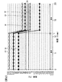
- FIG. 2 is a diagram showing the output characteristics of the temperature sensor circuit 11 during normal operation and during failure diagnosis.
- the vertical axis in FIG. 2 represents the values of the characteristic signal 18a and the diagnostic signal 18b output from the temperature sensor circuit 11, and the horizontal axis represents the measurement time.
- the characteristic signal 18a from the temperature sensor 10 is input to the microcomputer 17 to measure the temperature.
- a diagnostic signal 18b from the resistor 24 is input to the microcomputer 17 and measured as a temperature corresponding to the value of the diagnostic signal 18b.
- the output characteristic 30 indicates the output characteristic when there is no abnormality in the temperature sensor circuit 11.
- the output characteristic 31 is an output characteristic of the temperature sensor circuit 11 when an abnormality occurs in the resistor 14 and, for example, the resistance value of the resistor 14 is halved.
- the output characteristic 32 is an output characteristic of the temperature sensor circuit 11 when the resistance value of the resistor 14 is doubled.
- the output characteristic 33 is an output characteristic of the temperature sensor circuit 11 when the resistance value of the resistor 13 is doubled.
- the output characteristic 34 is an output characteristic of the temperature sensor circuit 11 when the resistance value of the resistor 13 is halved. As shown in FIG. 2, at the time of failure diagnosis, the output characteristics 31 to 34 are greatly different from the output characteristics 30 when there is no abnormality. Therefore, when the diagnostic signal 18b at the time of failure diagnosis is detected and the detected value falls within a predetermined detection range 35 determined based on the output characteristic 30, the temperature sensor circuit 11 is diagnosed as normal, and the detection range 35 is If exceeded, it is diagnosed as abnormal.
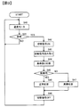
- FIG. 3 is a flowchart of the failure detection process executed by the microcomputer 17.
- the microcomputer 17 monitors the temperature by the temperature sensor 10. In the normal state where the temperature of the temperature sensor 10 is monitored, the switching signal 19 is turned off. That is, the temperature sensor 10 is connected to the temperature sensor circuit 11, and the characteristic signal 18 a from the temperature sensor 10 is input to the microcomputer 17, and the temperature is monitored by the microcomputer 17.
- the microcomputer 17 determines whether or not failure diagnosis of the temperature sensor circuit 11 is performed. For example, when a failure diagnosis command is received from a host control device of the microcomputer 17, it is determined that the failure diagnosis is performed, and when no command is received, it is determined that the failure diagnosis is not performed. If it is determined not to perform the failure diagnosis, the process returns to step S40 and the temperature monitoring is continued. When a temperature abnormality is detected during temperature monitoring, the temperature abnormality is notified to the host control device.
- step S41 If it is determined in step S41 that failure diagnosis is performed, the process proceeds to step S42.
- step S42 the microcomputer 17 turns on the switching signal 19. When the switching signal 19 is turned ON, a resistor 24 is connected to the temperature sensor circuit 11 instead of the temperature sensor 10, and a diagnostic signal 18 b from the resistor 24 is input to the microcomputer 17.
- the microcomputer 17 reads the input diagnostic signal 18b.
- the microcomputer 17 compares the value obtained by reading the diagnostic signal 18b with a predetermined reference value.
- the predetermined reference value is a diagnosis output from the temperature sensor circuit 11 when the resistor 24 having a predetermined resistance value is connected to the temperature sensor circuit 11 when the temperature sensor circuit 11 is operating normally. This is the value of the signal 18b.
- This reference value is determined by the voltage value of the power supply 12 and the resistance values of the resistors 13, 14 and 15.
- step S45 the microcomputer 17 determines whether the value of the diagnostic signal 18b is within a predetermined detection range 35 centered on the reference value shown in FIG. 2 based on the comparison result in step S44. If it is within the detection range 35, the temperature sensor circuit 11 is detected as normal, and information indicating normality is output to the host control device in step S46. On the other hand, if the detection range 35 is exceeded in step S45, an abnormality is detected, and information indicating abnormality is output to the host control device in step S47.
- step S48 After responding to the host controller in step S46 or step S47, the process proceeds to step S48, and the microcomputer 17 turns off the switching signal 19. Therefore, the temperature sensor 10 is connected to the temperature sensor circuit 11. Thereafter, the process returns to step S40, and the microcomputer 17 monitors the temperature of the temperature sensor 10.
- the failure of the resistors 13 and 14 of the temperature sensor circuit 11 can be appropriately detected with high accuracy.
- the failure detection apparatus 1 is replaced with a temperature sensor circuit 11 that is connected to the temperature sensor 10 and generates a characteristic signal 18a of the temperature sensor 10, a resistor 24 that outputs a predetermined signal value, and the temperature sensor 10.
- the first circuit unit 20 and the second circuit unit 22 that connect the resistor 24 to the temperature sensor circuit 11, and the diagnosis that is output from the temperature sensor circuit 11 based on a predetermined signal value when the resistor 24 is connected
- a microcomputer 17 for detecting a failure of the temperature sensor circuit 11 using the signal.
- the first circuit unit 20 and the second circuit unit 22 connect the temperature sensor 10 or the resistor 24 to the temperature sensor circuit 11 based on the switching signal output from the microcomputer 17. Thereby, it can switch suitably based on the switching signal output from the microcomputer 17 at the time of failure diagnosis.
- the microcomputer 17 determines whether the diagnostic signal 18b is within a predetermined range and detects a failure of the temperature sensor circuit 11. Thereby, the detection accuracy of the failure of the temperature sensor circuit 11 can be improved.
- the present invention can be implemented by modifying the embodiment described above as follows.
- (1) The temperature sensor 10 and the temperature sensor circuit 11 have been described as examples. However, other sensors such as a voltage output sensor can be similarly implemented instead of the temperature sensor 10.
- the resistor 24 having a predetermined resistance value of the second circuit unit 22 is provided, and the failure diagnosis of the temperature sensor circuit 11 is performed based on the voltage output from the resistor 24.
- a constant voltage source that outputs a predetermined voltage may be provided instead of the resistor 24, for example.
- the signal output unit that outputs a predetermined signal value outputs a predetermined signal value when connected to the temperature sensor circuit 11, and the temperature sensor circuit 11 can output a predetermined diagnostic signal 18b based on the output. Any one may be used as long as it is present.
- the failure diagnosis of the temperature sensor circuit 11 is performed according to the command from the host control device.
- the failure diagnosis may be performed under other conditions. For example, when the temperature detected by the temperature sensor 10 shows an abnormal value, a failure diagnosis of the temperature sensor circuit 11 is performed. As a result, if a failure of the temperature sensor circuit 11 is detected, it is determined that the temperature sensor circuit 11 has failed. If a failure of the temperature sensor circuit 11 has not been detected, the temperature sensor 10 has failed. Judge that In this way, when the temperature measurement is abnormal, it is possible to determine which of the temperature sensor 10 and the temperature sensor circuit 11 has failed.
- the present invention is not limited to the above-described embodiment, and other forms conceivable within the scope of the technical idea of the present invention are also included in the scope of the present invention as long as the characteristics of the present invention are not impaired. . Moreover, it is good also as a structure which combined the above-mentioned embodiment and a some modification.
Landscapes
- Physics & Mathematics (AREA)
- General Physics & Mathematics (AREA)
- Nonlinear Science (AREA)
- Measuring Temperature Or Quantity Of Heat (AREA)
- Testing Electric Properties And Detecting Electric Faults (AREA)
- Testing Of Short-Circuits, Discontinuities, Leakage, Or Incorrect Line Connections (AREA)
Abstract
Description
ステップS40では、マイクロコンピュータ17は温度センサ10による温度をモニタする。なお、温度センサ10の温度をモニタしている通常状態では切替信号19はOFFにされている。すなわち、温度センサ回路11には温度センサ10が接続されて、温度センサ10による特性信号18aがマイクロコンピュータ17へ入力され、マイクロコンピュータ17で温度をモニタしている。
(1)故障検出装置1は、温度センサ10に接続されて温度センサ10の特性信号18aを生成する温度センサ回路11と、所定の信号値を出力する抵抗体24と、温度センサ10に替えて、抵抗体24を温度センサ回路11に接続する第1回路部20および第2回路部22と、抵抗体24が接続されたときに所定の信号値に基づいて温度センサ回路11から出力される診断信号を用いて、温度センサ回路11の故障を検出するマイクロコンピュータ17とを備える。これにより、温度センサ回路11の故障の検出精度を高めることができる。
本発明は、以上説明した実施形態を次のように変形して実施することができる。
(1)温度センサ10と温度センサ回路11の例で説明した。しかし、温度センサ10の替わりに電圧出力センサなどその他のセンサでも同様に実施することができる。
10 温度センサ
11 温度センサ回路
12 電源
16 コンデンサ
17 マイクロコンピュータ
20 第1回路部
22 第2回路部
24 抵抗体
Claims (6)
- センサ部に接続されて前記センサ部の特性信号を生成するセンサ回路部と、
所定の信号値を出力する信号出力部と、
前記センサ部に替えて、前記信号出力部を前記センサ回路部に接続する切替回路部と、
前記信号出力部が接続されたときに前記所定の信号値に基づいて前記センサ回路部から出力される診断信号を用いて、前記センサ回路部の故障を検出する制御部とを備える故障検出装置。 - 請求項1に記載の故障検出装置であって、
前記切替回路部は、前記制御部から出力される切替信号に基づいて前記センサ部または前記信号出力部を前記センサ回路部に接続する故障検出装置。 - 請求項1または2に記載の故障検出装置であって、
前記切替回路部は、前記センサ部を無効にする第1回路部と、前記第1回路部が前記センサ部を無効にした状態で前記センサ回路部の接続先を前記信号出力部に切り替える第2回路部とを備える故障検出装置。 - 請求項1~3のいずれか一項に記載の故障検出装置であって、
前記制御部は、前記診断信号が所定の範囲内にあるかを判定して前記センサ回路部の故障を検出する故障検出装置。 - 請求項1に記載の故障検出装置であって、
前記センサ部は、温度センサである故障検出装置。 - 請求項1に記載の故障検出装置であって、
前記信号出力部は、所定の抵抗値を有する抵抗体である故障検出装置。
Priority Applications (4)
| Application Number | Priority Date | Filing Date | Title |
|---|---|---|---|
| DE112015005434.0T DE112015005434T5 (de) | 2015-01-06 | 2015-12-16 | Fehlerdetektionsvorrichtung |
| US15/540,432 US10514307B2 (en) | 2015-01-06 | 2015-12-16 | Fault detection apparatus |
| CN201580072331.9A CN107110717A (zh) | 2015-01-06 | 2015-12-16 | 故障检测装置 |
| JP2016568307A JP6329648B2 (ja) | 2015-01-06 | 2015-12-16 | 故障検出装置 |
Applications Claiming Priority (2)
| Application Number | Priority Date | Filing Date | Title |
|---|---|---|---|
| JP2015000929 | 2015-01-06 | ||
| JP2015-000929 | 2015-01-06 |
Publications (1)
| Publication Number | Publication Date |
|---|---|
| WO2016111128A1 true WO2016111128A1 (ja) | 2016-07-14 |
Family
ID=56355830
Family Applications (1)
| Application Number | Title | Priority Date | Filing Date |
|---|---|---|---|
| PCT/JP2015/085133 Ceased WO2016111128A1 (ja) | 2015-01-06 | 2015-12-16 | 故障検出装置 |
Country Status (5)
| Country | Link |
|---|---|
| US (1) | US10514307B2 (ja) |
| JP (1) | JP6329648B2 (ja) |
| CN (1) | CN107110717A (ja) |
| DE (1) | DE112015005434T5 (ja) |
| WO (1) | WO2016111128A1 (ja) |
Cited By (2)
| Publication number | Priority date | Publication date | Assignee | Title |
|---|---|---|---|---|
| JP2018156434A (ja) * | 2017-03-17 | 2018-10-04 | 東芝三菱電機産業システム株式会社 | プロセス制御システム |
| CN115343044A (zh) * | 2021-05-12 | 2022-11-15 | 西门子股份公司 | 用于对装置进行状态监控的方法和组件 |
Families Citing this family (3)
| Publication number | Priority date | Publication date | Assignee | Title |
|---|---|---|---|---|
| CN108318154A (zh) * | 2018-01-29 | 2018-07-24 | 广东美的暖通设备有限公司 | 温度传感器故障诊断电路、诊断方法及制冷设备 |
| CN112986863B (zh) * | 2021-02-04 | 2024-04-12 | 三一重能股份有限公司 | 温度检测系统的线路检测方法、装置和电子设备 |
| WO2024106137A1 (ja) * | 2022-11-15 | 2024-05-23 | パナソニックエナジー株式会社 | 電池パック、温度測定回路及び電池パックの故障診断方法 |
Citations (4)
| Publication number | Priority date | Publication date | Assignee | Title |
|---|---|---|---|---|
| JP2005345380A (ja) * | 2004-06-04 | 2005-12-15 | Osaka Gas Co Ltd | 故障検知機能付き電子回路 |
| JP2006200914A (ja) * | 2005-01-18 | 2006-08-03 | Nissin Kogyo Co Ltd | 温度検出回路 |
| JP2009236536A (ja) * | 2008-03-26 | 2009-10-15 | Calsonic Kansei Corp | メータ自己診断装置 |
| JP2013130545A (ja) * | 2011-12-22 | 2013-07-04 | Sanyo Electric Co Ltd | 切替判定装置及び異常判定方法 |
Family Cites Families (14)
| Publication number | Priority date | Publication date | Assignee | Title |
|---|---|---|---|---|
| JPS5479085A (en) * | 1977-12-05 | 1979-06-23 | Matsushita Electric Ind Co Ltd | Temperature measuring apparatus |
| GB2157515B (en) * | 1984-02-01 | 1987-10-07 | Suwa Seikosha Kk | Electronic thermometer |
| JP3808265B2 (ja) * | 1999-02-12 | 2006-08-09 | 矢崎総業株式会社 | 電源供給制御装置及び電源供給制御方法 |
| US6448671B1 (en) * | 1999-08-05 | 2002-09-10 | Trw Inc. | Distributed vehicle safety system having fault protection |
| JP3668708B2 (ja) * | 2001-10-22 | 2005-07-06 | 株式会社日立製作所 | 故障検知システム |
| JP2005009924A (ja) * | 2003-06-17 | 2005-01-13 | Honda Motor Co Ltd | 温度センサ回路の故障診断装置 |
| JP2006126053A (ja) * | 2004-10-29 | 2006-05-18 | Jidosha Denki Kogyo Co Ltd | 故障検出装置 |
| DE102005037717B3 (de) * | 2005-08-10 | 2006-12-21 | Daimlerchrysler Ag | Verfahren und Vorrichtung zur Diagnose eines Außentemperatursensors |
| JP2008206214A (ja) * | 2007-02-16 | 2008-09-04 | Ricoh Co Ltd | スイッチングレギュレータ |
| GB2482004A (en) * | 2010-07-14 | 2012-01-18 | Influx Measurements Ltd | Monitoring apparatus |
| JP5110154B2 (ja) * | 2010-11-10 | 2012-12-26 | 株式会社デンソー | 電圧検出装置および電圧検出システム |
| JP2013153563A (ja) * | 2012-01-24 | 2013-08-08 | Toshiba Corp | 半導体集積回路装置およびdc−dcコンバータ |
| JP5655824B2 (ja) * | 2012-07-20 | 2015-01-21 | 株式会社デンソー | 温度検出装置 |
| JP6474305B2 (ja) * | 2015-04-23 | 2019-02-27 | 株式会社日立製作所 | 太陽光発電システムの診断方法及び監視装置 |
-
2015
- 2015-12-16 JP JP2016568307A patent/JP6329648B2/ja active Active
- 2015-12-16 WO PCT/JP2015/085133 patent/WO2016111128A1/ja not_active Ceased
- 2015-12-16 CN CN201580072331.9A patent/CN107110717A/zh active Pending
- 2015-12-16 DE DE112015005434.0T patent/DE112015005434T5/de active Pending
- 2015-12-16 US US15/540,432 patent/US10514307B2/en active Active
Patent Citations (4)
| Publication number | Priority date | Publication date | Assignee | Title |
|---|---|---|---|---|
| JP2005345380A (ja) * | 2004-06-04 | 2005-12-15 | Osaka Gas Co Ltd | 故障検知機能付き電子回路 |
| JP2006200914A (ja) * | 2005-01-18 | 2006-08-03 | Nissin Kogyo Co Ltd | 温度検出回路 |
| JP2009236536A (ja) * | 2008-03-26 | 2009-10-15 | Calsonic Kansei Corp | メータ自己診断装置 |
| JP2013130545A (ja) * | 2011-12-22 | 2013-07-04 | Sanyo Electric Co Ltd | 切替判定装置及び異常判定方法 |
Cited By (3)
| Publication number | Priority date | Publication date | Assignee | Title |
|---|---|---|---|---|
| JP2018156434A (ja) * | 2017-03-17 | 2018-10-04 | 東芝三菱電機産業システム株式会社 | プロセス制御システム |
| CN115343044A (zh) * | 2021-05-12 | 2022-11-15 | 西门子股份公司 | 用于对装置进行状态监控的方法和组件 |
| US12276682B2 (en) | 2021-05-12 | 2025-04-15 | Siemens Aktiengesellschaft | Method for monitoring the status of an apparatus and assembly |
Also Published As
| Publication number | Publication date |
|---|---|
| CN107110717A (zh) | 2017-08-29 |
| JPWO2016111128A1 (ja) | 2017-08-31 |
| DE112015005434T5 (de) | 2017-08-17 |
| US20170363481A1 (en) | 2017-12-21 |
| JP6329648B2 (ja) | 2018-05-23 |
| US10514307B2 (en) | 2019-12-24 |
Similar Documents
| Publication | Publication Date | Title |
|---|---|---|
| JP6329648B2 (ja) | 故障検出装置 | |
| JP5575986B2 (ja) | プロセス流体温度計測器 | |
| CN110595524B (zh) | 传感器饱和故障检测 | |
| JP6158029B2 (ja) | 電子制御装置 | |
| JP4296811B2 (ja) | 物理量センサ装置 | |
| JP5832751B2 (ja) | 自己診断可能な電子回路及び磁界検出装置 | |
| KR101764735B1 (ko) | 누수감지센서의 구동회로 | |
| JP2004294442A (ja) | 故障検出を備えたエンジン速度センサ | |
| US9574925B2 (en) | Fluid measurement device having a circuit for precise flow measurement | |
| KR101493213B1 (ko) | 아날로그 센서의 종류 판별 장치 | |
| JP2014211382A (ja) | センサ装置 | |
| JPWO2017150013A1 (ja) | 温度検出回路 | |
| TWI802375B (zh) | 電流感測器的錯誤排除系統及方法 | |
| JP2007068249A (ja) | 電気自動車用リーク検出装置 | |
| KR100944315B1 (ko) | 에어필터의 막힘 감지 장치 및 그 방법 | |
| KR102862437B1 (ko) | 온도 센싱에 기초한 고장 진단 검출 장치 및 고장 진단 검출 방법 | |
| EP3357203A1 (en) | Process variable transmitter with self-learning loop diagnostics | |
| GB2334588A (en) | Monitoring correct operation of a sensor module comprising a Wheatstone bridge circuit | |
| JP5177001B2 (ja) | 故障検出装置及び故障検出方法 | |
| KR20150046947A (ko) | 램프 고장진단 시스템 및 그 방법 | |
| JP5040719B2 (ja) | 2線式フィールド機器とフィールドバスシステム | |
| JP2015021954A (ja) | 電流制御装置 | |
| JP2012047636A (ja) | ブリッジセンサの断線検出装置 | |
| JP6673154B2 (ja) | オープンコレクタ方式の回転センサの自己診断回路 | |
| JPWO2020012929A1 (ja) | 車載電子制御装置 |
Legal Events
| Date | Code | Title | Description |
|---|---|---|---|
| 121 | Ep: the epo has been informed by wipo that ep was designated in this application |
Ref document number: 15877001 Country of ref document: EP Kind code of ref document: A1 |
|
| ENP | Entry into the national phase |
Ref document number: 2016568307 Country of ref document: JP Kind code of ref document: A |
|
| WWE | Wipo information: entry into national phase |
Ref document number: 15540432 Country of ref document: US |
|
| WWE | Wipo information: entry into national phase |
Ref document number: 112015005434 Country of ref document: DE |
|
| 122 | Ep: pct application non-entry in european phase |
Ref document number: 15877001 Country of ref document: EP Kind code of ref document: A1 |