WO2016111103A1 - 光音響計測用プローブ並びにそれを備えたプローブユニットおよび光音響計測装置 - Google Patents
光音響計測用プローブ並びにそれを備えたプローブユニットおよび光音響計測装置 Download PDFInfo
- Publication number
- WO2016111103A1 WO2016111103A1 PCT/JP2015/084107 JP2015084107W WO2016111103A1 WO 2016111103 A1 WO2016111103 A1 WO 2016111103A1 JP 2015084107 W JP2015084107 W JP 2015084107W WO 2016111103 A1 WO2016111103 A1 WO 2016111103A1
- Authority
- WO
- WIPO (PCT)
- Prior art keywords
- probe
- photoacoustic
- acoustic wave
- light emitting
- detecting element
- Prior art date
Links
Images


Classifications
-
- A—HUMAN NECESSITIES
- A61—MEDICAL OR VETERINARY SCIENCE; HYGIENE
- A61B—DIAGNOSIS; SURGERY; IDENTIFICATION
- A61B5/00—Measuring for diagnostic purposes; Identification of persons
- A61B5/0093—Detecting, measuring or recording by applying one single type of energy and measuring its conversion into another type of energy
- A61B5/0095—Detecting, measuring or recording by applying one single type of energy and measuring its conversion into another type of energy by applying light and detecting acoustic waves, i.e. photoacoustic measurements
-
- A—HUMAN NECESSITIES
- A61—MEDICAL OR VETERINARY SCIENCE; HYGIENE
- A61B—DIAGNOSIS; SURGERY; IDENTIFICATION
- A61B8/00—Diagnosis using ultrasonic, sonic or infrasonic waves
- A61B8/13—Tomography
-
- A—HUMAN NECESSITIES
- A61—MEDICAL OR VETERINARY SCIENCE; HYGIENE
- A61B—DIAGNOSIS; SURGERY; IDENTIFICATION
- A61B5/00—Measuring for diagnostic purposes; Identification of persons
- A61B5/72—Signal processing specially adapted for physiological signals or for diagnostic purposes
- A61B5/7203—Signal processing specially adapted for physiological signals or for diagnostic purposes for noise prevention, reduction or removal
-
- G—PHYSICS
- G01—MEASURING; TESTING
- G01N—INVESTIGATING OR ANALYSING MATERIALS BY DETERMINING THEIR CHEMICAL OR PHYSICAL PROPERTIES
- G01N29/00—Investigating or analysing materials by the use of ultrasonic, sonic or infrasonic waves; Visualisation of the interior of objects by transmitting ultrasonic or sonic waves through the object
- G01N29/04—Analysing solids
- G01N29/06—Visualisation of the interior, e.g. acoustic microscopy
- G01N29/0654—Imaging
- G01N29/0672—Imaging by acoustic tomography
-
- G—PHYSICS
- G01—MEASURING; TESTING
- G01N—INVESTIGATING OR ANALYSING MATERIALS BY DETERMINING THEIR CHEMICAL OR PHYSICAL PROPERTIES
- G01N29/00—Investigating or analysing materials by the use of ultrasonic, sonic or infrasonic waves; Visualisation of the interior of objects by transmitting ultrasonic or sonic waves through the object
- G01N29/22—Details, e.g. general constructional or apparatus details
- G01N29/24—Probes
- G01N29/2418—Probes using optoacoustic interaction with the material, e.g. laser radiation, photoacoustics
-
- A—HUMAN NECESSITIES
- A61—MEDICAL OR VETERINARY SCIENCE; HYGIENE
- A61B—DIAGNOSIS; SURGERY; IDENTIFICATION
- A61B2562/00—Details of sensors; Constructional details of sensor housings or probes; Accessories for sensors
- A61B2562/02—Details of sensors specially adapted for in-vivo measurements
- A61B2562/0204—Acoustic sensors
-
- A—HUMAN NECESSITIES
- A61—MEDICAL OR VETERINARY SCIENCE; HYGIENE
- A61B—DIAGNOSIS; SURGERY; IDENTIFICATION
- A61B2576/00—Medical imaging apparatus involving image processing or analysis
-
- A—HUMAN NECESSITIES
- A61—MEDICAL OR VETERINARY SCIENCE; HYGIENE
- A61B—DIAGNOSIS; SURGERY; IDENTIFICATION
- A61B5/00—Measuring for diagnostic purposes; Identification of persons
- A61B5/02—Detecting, measuring or recording pulse, heart rate, blood pressure or blood flow; Combined pulse/heart-rate/blood pressure determination; Evaluating a cardiovascular condition not otherwise provided for, e.g. using combinations of techniques provided for in this group with electrocardiography or electroauscultation; Heart catheters for measuring blood pressure
- A61B5/02007—Evaluating blood vessel condition, e.g. elasticity, compliance
-
- G—PHYSICS
- G01—MEASURING; TESTING
- G01N—INVESTIGATING OR ANALYSING MATERIALS BY DETERMINING THEIR CHEMICAL OR PHYSICAL PROPERTIES
- G01N2291/00—Indexing codes associated with group G01N29/00
- G01N2291/10—Number of transducers
- G01N2291/106—Number of transducers one or more transducer arrays
-
- G—PHYSICS
- G16—INFORMATION AND COMMUNICATION TECHNOLOGY [ICT] SPECIALLY ADAPTED FOR SPECIFIC APPLICATION FIELDS
- G16H—HEALTHCARE INFORMATICS, i.e. INFORMATION AND COMMUNICATION TECHNOLOGY [ICT] SPECIALLY ADAPTED FOR THE HANDLING OR PROCESSING OF MEDICAL OR HEALTHCARE DATA
- G16H30/00—ICT specially adapted for the handling or processing of medical images
- G16H30/40—ICT specially adapted for the handling or processing of medical images for processing medical images, e.g. editing
Definitions
- the present invention relates to a photoacoustic measurement probe that irradiates a subject with light and receives the light to detect a photoacoustic wave generated in the subject.
- the present invention also relates to a probe unit and a photoacoustic measuring device provided with such a probe.
- This measurement method irradiates a subject with pulsed light having an appropriate wavelength (for example, a wavelength band of visible light, near infrared light, or mid-infrared light), and an absorbing substance in the subject is irradiated with the pulsed light.
- a photoacoustic wave which is an elastic wave generated as a result of absorbing energy, is detected, and the concentration of the absorbing substance is quantitatively measured.
- the absorbing substance in the subject is, for example, glucose or hemoglobin contained in blood.
- a technique for detecting such a photoacoustic wave and generating a photoacoustic image based on the detection signal is called photoacoustic imaging (PAI) or photoacoustic tomography (PAT). Yes.
- a light emitting unit that emits measurement light such as pulsed light toward the subject and a portion of the subject that has been irradiated with the measurement light are emitted.
- a probe that includes an acoustic wave detecting element that detects an acoustic wave and a housing that accommodates the light emitting unit and the acoustic wave detecting element therein is often used.
- the present invention has been made in view of the above circumstances, and an object thereof is to provide a photoacoustic measurement probe capable of preventing the occurrence of artifacts.
- an object of the present invention is to provide a probe unit and a photoacoustic measuring apparatus that can prevent the occurrence of artifacts.
- One photoacoustic measurement probe is: A light emitting section for emitting measurement light toward the subject; An acoustic wave detecting element that detects an acoustic wave emitted from a portion of the subject that has been irradiated with the measurement light; and In a photoacoustic measurement probe having a surface directed to a subject at the time of use and having a housing that houses a light emitting portion and an acoustic wave detection element inside, Between the light emitting part and the acoustic wave detection element, at least one slit that extends from the surface of the housing toward the inside of the housing and that is open on the surface of the housing is provided.
- both end portions of the slit are located outside the both end portions of the acoustic wave detecting element.
- At least one light emitting portion is disposed on each side of the acoustic wave detection element with the acoustic wave detection element interposed therebetween.
- one of the light emitting parts provided on both sides of the acoustic wave detecting element and the acoustic wave detecting element A slit disposed between the other end of the light emitting portion disposed on both sides of the acoustic wave detecting element and the slit disposed between the acoustic wave detecting element and the other. It is desirable that the acoustic wave detecting elements are surrounded by the slits by being connected to each other by another slit.
- the other slit is not discontinuous on the way and the acoustic wave detecting element is surrounded by the slit over the entire circumference.
- the present invention is not limited thereto, and the other slit may be discontinuous in the middle.
- Another photoacoustic measurement probe is: A light emitting section for emitting measurement light toward the subject; An acoustic wave detecting element that detects an acoustic wave emitted from a portion of the subject that has been irradiated with the measurement light; and
- a photoacoustic measurement probe having a surface directed to a subject at the time of use and having a housing that houses a light emitting portion and an acoustic wave detection element inside, A set in which two materials having different acoustic impedances are brought into close contact with each other, and a set of materials constituting an interface extending from the surface of the casing toward the inside of the casing between the light emitting portion and the acoustic wave detection element. , At least one set.
- both ends of the interface with respect to the direction orthogonal to the arrangement direction of the light emitting portion and the acoustic wave detection element. It is desirable that each of the portions is located outside the both end portions of the acoustic wave detection element.
- At least one light emitting portion is disposed on each side of the acoustic wave detection element with the acoustic wave detection element interposed therebetween. desirable.
- the acoustic wave detection element is surrounded by the interface by being connected by another interface in which materials having different acoustic impedances are brought into close contact with each other.
- the other interface is not discontinuous in the middle, and the acoustic wave detecting element is surrounded by the interface over the entire circumference.
- the present invention is not limited to this, and the other interface may be discontinuous on the way.
- a slit extending from the surface of the housing toward the inside of the housing is provided between the light emitting portion and the acoustic wave detection element. Furthermore, it is desirable that a material having an acoustic impedance different from that of the material constituting the housing is filled.
- the slit When the slit is filled with a material having an acoustic impedance different from that of the material constituting the housing, a material having an acoustic impedance different from that of the material constituting the housing is covered over the entire depth of the slit. It is desirable that it is filled.
- the slit when the slit is filled with a material having an acoustic impedance different from that of the material constituting the housing, the material having an acoustic impedance different from that of the material constituting the housing matches the surface of the housing. It may be filled from the position to a position shallower than the depth of the slit.
- a fluorinated liquid is preferably used as a material having an acoustic impedance different from that of the material constituting the casing.
- the “fluorinated liquid” refers to a liquid composed of one or a mixture of perfluoropolyethers, perfluorocarbons, hydrofluoropolyethers, hydrofluoroethers. .
- the housing is composed of housing materials having different acoustic impedances in a portion including the light emitting portion and a portion including the acoustic wave detection element, and the above-described interface is formed by the two housing materials. It is also possible to configure.
- the probe unit according to the present invention is: The photoacoustic measurement probe according to the present invention described above, A light source that outputs measurement light; And a connection part for optically connecting the measurement light to the light emitting part of the photoacoustic measurement probe.
- the photoacoustic measuring device is: The photoacoustic measurement probe according to the present invention described above, And a signal processing unit that generates a photoacoustic image based on a photoacoustic wave detection signal output from the photoacoustic measurement probe.
- At least one slit that opens from the surface of the housing toward the inside of the housing and that opens to the housing surface is provided between the light emitting portion and the acoustic wave detection element. Therefore, the photoacoustic wave generated as described above and traveling toward the acoustic wave detecting element is reflected and attenuated at the interface between the air in the slit and the housing material. Therefore, high-intensity photoacoustic waves are not incident on the acoustic wave detection element, and the generation of artifacts is prevented.
- a pair of two materials having different acoustic impedances is brought into close contact with each other from the surface of the housing between the light emitting part and the acoustic wave detection element. Since at least one set of materials constituting the interface extending toward the inside of the housing is provided, the photoacoustic wave generated as described above and traveling toward the acoustic wave detection element is reflected at the interface. Attenuate. Therefore, high-intensity photoacoustic waves are not incident on the acoustic wave detection element, and the generation of artifacts is prevented.
- FIG. 1 is a side sectional view showing a probe according to a first embodiment of the present invention.
- Front view of the probe of FIG. Side sectional view showing a probe according to a second embodiment of the present invention.
- FIG. 1 is a schematic diagram showing the overall configuration of the photoacoustic measurement apparatus 10 of the present embodiment.
- FIGS. 2 and 3 are respectively photoacoustic measurement probes (hereinafter simply referred to as probes) used in the photoacoustic measurement apparatus 10. 2) is a side sectional view and a front view showing 11. In FIG. 1, the shape of the probe 11 is schematically shown.
- the photoacoustic measuring apparatus 10 of this embodiment has a function which produces
- a probe ultrasonic probe
- a laser unit 13 a laser unit 13
- a display unit 14 and the like.
- the probe 11 has, for example, a function of irradiating measurement light and ultrasonic waves toward a subject M that is a living body, and a function of detecting an acoustic wave U propagating in the subject M. That is, the probe 11 can perform irradiation (transmission) of ultrasonic waves to the subject M, and detection (reception) of reflected ultrasonic waves (reflected acoustic waves) reflected by the subject M and returning. Further, the probe 11 can detect photoacoustic waves generated in the subject M.
- acoustic wave is a term including ultrasonic waves and photoacoustic waves.
- ultrasonic wave means an elastic wave transmitted by the probe and its reflected wave
- photoacoustic wave means an elastic wave emitted when the absorber 65 absorbs measurement light.
- absorber 65 in the subject M include blood vessels and metal members.
- the probe 11 is disposed on the both sides of the transducer array 20 with the transducer array 20 as an acoustic wave detecting element and the transducer array 20 in between.
- a total of two light emitting portions 40 and a housing 50 that accommodates the transducer array 20 and the two light emitting portions 40 are provided.
- the transducer array 20 is located, for example, about 1 mm inside from the upper end surface in FIG.
- the transducer array 20 also functions as an ultrasonic transmission element.
- the transducer array 20 is connected to the ultrasonic transmission circuit and the acoustic wave reception circuit via the wiring 20a.
- an optical fiber 60 is connected to the probe 11 as a connecting portion that guides laser light L, which is measurement light emitted from a laser unit 13 described later, to the light emitting portion 40.
- the transducer array 20 is composed of, for example, a plurality of ultrasonic transducers arranged one-dimensionally or two-dimensionally.
- the ultrasonic vibrator is a piezoelectric element made of a polymer film such as piezoelectric ceramics or polyvinylidene fluoride (PVDF).
- the ultrasonic transducer has a function of converting the received acoustic wave U into an electrical signal.
- the electric signal output from the transducer array 20 is input to a receiving circuit 21 described later.
- probes 11 corresponding to sector scanning, those corresponding to linear scanning, those corresponding to convex scanning, etc. are prepared, and an appropriate one is selected and used according to the imaging region.
- the transducer array 20 may include an acoustic lens.
- the ultrasonic transducer has a function of transmitting ultrasonic waves. That is, when an alternating voltage is applied to the ultrasonic vibrator, the ultrasonic vibrator generates an ultrasonic wave having a frequency corresponding to the frequency of the alternating voltage. Note that transmission and reception of ultrasonic waves may be separated from each other. That is, for example, ultrasonic waves may be transmitted from a position different from the probe 11, and reflected ultrasonic waves with respect to the transmitted ultrasonic waves may be received by the probe 11.
- the light emitting unit 40 is a part that irradiates the subject M with the laser light L guided by the optical fiber 60. As shown in FIG. 2 and FIG. 3, in this embodiment, the two light emitting units 40 are arranged with the transducer array 20 in between, for example, in the elevation direction of the transducer array 20 (a plurality of ultrasonic transducers are arranged). When arranged one-dimensionally, they are arranged on both sides of a direction perpendicular to the arrangement direction and parallel to the detection surface.
- the light emitting unit 40 includes, as an example, a first light guide member 41, a diffusion unit 42, and a second light guide member 43.
- the first light guide member 41, the diffusing portion 42, and the second light guide member 43 are arranged in series with respect to the traveling direction of the measurement light, and these are fixed by a fixed frame (not shown).
- the first light guide member 41 may be air.
- the light exit end face of the optical fiber 60 described above is optically coupled to the light entrance end face of the first light guide member 41.
- a light guide plate can be used, for example.
- the light guide plate is a specially processed surface of an acrylic plate or a quartz plate, for example, and emits light incident from one end surface with uniform in-plane intensity from the other end surface.
- the first light guide member 41 guides the laser light L guided by the optical fiber 60 to the diffusion unit 42.
- the diffusing unit 42 diffuses the laser light L emitted from the first light guide member 41. Thereby, the irradiation range of the laser beam L is further expanded.
- a diffusion plate can be used.
- a lens diffusion plate in which microlenses are randomly arranged on the substrate, a quartz plate in which diffusion fine particles are dispersed, or the like can be used.
- a holographic diffusion plate or an engineering diffusion plate may be used as the lens diffusion plate.
- the diffusion part 42 does not have to be a member independent of the first light guide member 41.
- a diffusion layer may be provided at the light emitting end portion of the first light guide member 41 to form the diffusing portion 42, or a diffusion surface may be provided at the light emitting end surface to form the diffusing portion 42.
- the diffusing portion 42 is fixed to a fixing member (not shown) by, for example, an adhesive.
- an adhesive having a high light diffusibility. This is because when the adhesive adheres to the lens diffusing surface, the light diffusibility of the portion is lost, and strong light may be emitted locally.
- an adhesive having light diffusibility is used, light can be diffused by the light diffusibility of the adhesive even when the adhesive adheres to the lens diffusion surface.
- an adhesive such as silicone rubber containing a white pigment can be used.
- An example of the white pigment is TiO 2 .
- the content of TiO 2 is preferably 1% by weight to 20% by weight.
- the silicone rubber for example, liquid rubber KE-45-W manufactured by Shin-Etsu Chemical Co., Ltd. can be used.
- the second light guide member 43 emits the laser light L diffused by the diffusion unit 42 toward the subject M.
- the light emitting end portion of the second light guide member 43 is fitted into the light window portion (opening portion) of the housing 50, and functions to fill a gap between the light window portions.
- they may be provided on the light incident end portion and the light incident end surface of the second light guide member 43, respectively.
- the laser unit 13 shown in FIG. 1 has a flash lamp excitation Q-switch solid laser such as a Q-switch alexandrite laser, for example, and emits laser light L as measurement light to be irradiated onto the subject M.
- the laser unit 13 is configured to receive a trigger signal from the control unit 34 of the ultrasonic unit 12 and output the laser light L.
- the laser unit 13 preferably outputs pulsed laser light L having a pulse width of 1 to 100 nsec (nanoseconds).
- the wavelength of the laser light L is appropriately selected according to the light absorption characteristics of the absorber 65 in the subject M to be measured.
- the wavelength be a wavelength belonging to the near-infrared wavelength region.
- the near-infrared wavelength region means a wavelength region of about 700 to 850 nm.
- the wavelength of the laser beam L is naturally not limited to this.
- the laser beam L may be a single wavelength or may include a plurality of wavelengths such as 750 nm and 800 nm. When the laser light L includes a plurality of wavelengths, light of these wavelengths may be irradiated to the subject M at the same time, or may be irradiated while being switched alternately.
- the laser unit 13 is also capable of outputting laser light in the near-infrared wavelength region as well as YAG-SHG (Second harmonic generation) -OPO (Optical Parametric Oscillation). : Optical parametric oscillation) laser, Ti-Sapphire (titanium-sapphire) laser, or the like.
- the laser unit 13 as a light source constitutes a probe unit together with the probe 11 and the optical fiber 60.
- the optical fiber 60 guides the laser light L emitted from the laser unit 13 to the two light emitting units 40.
- the optical fiber 60 is not particularly limited, and a known fiber such as a quartz fiber can be used.
- a known fiber such as a quartz fiber can be used.
- one thick optical fiber may be used, or a bundle fiber in which a plurality of optical fibers are bundled may be used.
- the bundle fiber is arranged so that the laser light L is incident from the light incident end face of the bundled fiber portion, and the fiber portion branched into two of the bundle fiber is used.
- the light emitting portions 40 are coupled to the light emitting end surfaces, respectively.
- the ultrasonic unit 12 includes a reception circuit 21, a reception memory 22, a data separation unit 23, a photoacoustic image generation unit 24, an ultrasonic image generation unit 29, a display control unit 30, a transmission control circuit 33, and a control unit 34.
- the control unit 34 controls each unit of the photoacoustic measurement apparatus 10, and includes a trigger control circuit (not shown) in the present embodiment.
- This trigger control circuit sends a light trigger signal to the laser unit 13 when acquiring a photoacoustic image, for example.
- the flash lamp of the excitation source is turned on in the Q-switch solid-state laser of the laser unit 13, and excitation of the laser rod is started. While the excited state of the laser rod is maintained, the laser unit 13 can output the laser light L.
- the control unit 34 then transmits a Q switch trigger signal from the trigger control circuit to the laser unit 13. That is, the control unit 34 controls the output timing of the laser light L from the laser unit 13 by this Q switch trigger signal. Further, the control unit 34 transmits a sampling trigger signal to the receiving circuit 21 simultaneously with transmission of the Q switch trigger signal.
- This sampling trigger signal defines the start timing of the photoacoustic signal sampling in the AD converter (Analog-to-Digital converter) of the receiving circuit 21. As described above, by using the sampling trigger signal, it is possible to sample the photoacoustic signal in synchronization with the output of the laser light L.
- the control unit 34 transmits an ultrasonic transmission trigger signal that instructs the transmission control circuit 33 to perform ultrasonic transmission when acquiring an ultrasonic image.
- the transmission control circuit 33 transmits ultrasonic waves from the probe 11.
- the control unit 34 transmits a sampling trigger signal to the receiving circuit 21 in synchronization with the timing of ultrasonic transmission, and starts sampling of the reflected ultrasonic signal.
- the position of the probe 11 is gradually changed with respect to the subject M, for example, in the above-described elevation direction, and the subject M is irradiated with the laser light L or ultrasonic waves. Are scanned. Therefore, sampling of the photoacoustic signal or reflected ultrasonic signal is performed while shifting the acoustic wave detection line one line at a time in synchronization with this scanning.
- the scanning may be performed by the operator manually moving the probe 11 or may be performed using an automatic scanning mechanism.
- the receiving circuit 21 receives the detection signal output from the probe 11 and stores the received detection signal in the reception memory 22.
- the reception circuit 21 typically includes a low noise amplifier, a variable gain amplifier, a low-pass filter, and an AD converter.
- the detection signal of the probe 11 is amplified by a low noise amplifier, then gain adjusted according to the depth by a variable gain amplifier, a high frequency component is cut by a low-pass filter, converted to a digital signal by an AD converter, and received.
- the receiving circuit 21 is composed of, for example, one IC (Integrated Circuit).
- the probe 11 outputs a photoacoustic wave detection signal and a reflected ultrasonic detection signal. Accordingly, digitized photoacoustic waves and reflected ultrasonic detection signals (sampling data) are stored in the reception memory 22.
- the data separation unit 23 reads sampling data (photoacoustic data) of the photoacoustic wave detection signal from the reception memory 22 and transmits it to the photoacoustic image generation unit 24. Further, the data separation unit 23 reads sampling data (reflection ultrasonic data) of the reflected ultrasonic detection signal from the reception memory 22 and transmits it to the ultrasonic image generation unit 29.
- the photoacoustic image generation unit 24 adds the photoacoustic data stored in the reception memory 22 to each other with a delay time corresponding to the position of the transducer array 20 of the probe 11 to reconstruct data for one line, Data of a tomographic image (photoacoustic image) is generated based on the photoacoustic data of each line.
- this photoacoustic image generation part 24 may replace with a delay addition method, and may perform a reconfiguration
- the photoacoustic image generation unit 24 may perform reconstruction using a Hough transform method or a Fourier transform method.
- the photoacoustic image generation unit 24 outputs the photoacoustic image data generated as described above to the display control unit 30.
- the photoacoustic image generation unit 24 constitutes a signal processing unit in the photoacoustic measurement apparatus of the present invention.
- the ultrasonic image generation unit 29 performs processing similar to that for the photoacoustic data on the reflected ultrasonic data stored in the reception memory 22 to obtain tomographic image (ultrasonic image) data. Generate.
- the ultrasonic image generation unit 29 outputs the ultrasonic image data generated as described above to the display control unit 30.
- the display control unit 30 causes the display unit 14 to display a photoacoustic image based on the photoacoustic image data and an ultrasonic image based on the ultrasonic image data. These two images are displayed separately or combined and displayed on the display unit 14 as a combined image. In the latter case, the display control unit 30 performs image composition by superimposing a photoacoustic image and an ultrasonic image, for example. Thus, if an ultrasonic image is generated and displayed in addition to the photoacoustic image, a portion that cannot be imaged by the photoacoustic image can be observed in the ultrasonic image.
- the probe 11 is provided with slits 45 between the transducer array 20 and one light emitting unit 40 and between the transducer array 20 and the other light emitting unit 40. It has been.
- Each slit 45 extends from the surface 50a of the housing 50 toward the inside of the housing and is open to the housing surface 50a.
- FIG. 12 shows an example of a conventional probe that does not have the slit 45 as described above.
- FIG. 12 shows a side cross-sectional shape of the probe.
- the same elements as those in FIG. 2 described above are denoted by the same reference numerals, and description thereof will be omitted unless necessary (the same applies hereinafter).
- artifacts can occur due to the following causes. That is, as shown in FIG. 12, when the measurement light (laser light) L is emitted from the light emitting unit 40, the measurement light L may irradiate the vicinity of the surface of the housing 50.
- a photoacoustic wave is generated from the portion of the casing 50 that has absorbed the measurement light L, as schematically shown by an arrow A in the figure, and this photoacoustic wave is detected by the transducer array 20 to produce an artifact. It happens.
- the probe for photoacoustic measurement of the present invention is obtained based on the above new findings.
- the photoacoustic wave generated as described above is attenuated by the slit 45 provided between the transducer array 20 and the light emitting unit 40. That is, the air in the slit and the material of the housing 50 are in contact with each other at the two side surfaces of the slit 45 (the side surface on the transducer array 20 side and the side surface on the light emitting unit 40 side). Both of them are greatly different in acoustic impedance.
- the photoacoustic wave generated in the vicinity of one light emitting portion 40 and traveling toward the transducer array 20 is reflected and attenuated at the two side surfaces of the slit 45. Therefore, high-intensity photoacoustic waves do not reach the transducer array 20. The same applies to the photoacoustic wave that occurs in the vicinity of another light emitting unit 40 and travels toward the transducer array 20.
- the acoustic impedance of air is about 440 Pa ⁇ s / m
- the material of the housing 50 is, for example, ABS (acrylonitrile butadiene styrene copolymer synthetic resin)
- the acoustic impedance is 2.3 ⁇ 10 6 Pa ⁇ s. / M or so.
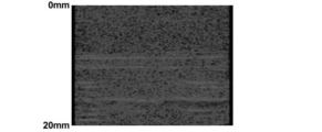
- FIG. 13 and FIG. 14 show the results of confirming the above description by actually generating and displaying a photoacoustic image (tomographic image).
- FIG. 13 is a photograph showing a photoacoustic image generated using a conventional probe having the same configuration as that of the probe 11 of this embodiment except that the slit 45 is not provided
- FIG. 14 is a photo of the probe 11 of this embodiment. It is a photograph which shows the photoacoustic image produced
- These photoacoustic images are both background images subjected to enhancement processing, and the numbers shown on the left side of each figure indicate the distance from the probe surface, that is, the depth position of the subject.
- horizontal stripe-shaped artifacts are recognized from a depth position close to 10 mm to a position of 20 mm, whereas such obvious artifacts are not recognized in the image of FIG. 14.
- each slit 45 is larger than the length of the transducer array 20. That is, when the probe 11 is viewed in plan from the surface (front surface), both end portions of the slit 45 are respectively in the direction orthogonal to the arrangement direction of the light emitting unit 40 and the transducer array 20 (left-right direction in FIG. 3).
- the transducer array 20 is located outside the both end portions. With such a configuration, the photoacoustic wave generated near the side end portion of the light emitting portion 40 is also reliably incident on the slit 45 and attenuated.
- FIG. 4 shows a side cross-sectional shape of the probe 211 of the present embodiment.
- two slits 45 similar to those in the probe 11 described above are provided.
- a portion of each slit 45 close to the housing surface 50 a is filled with a blocking member 46.
- Each blocking member 46 is arranged so that the surface thereof is flush with the housing surface 50 a and in close contact with the housing 50. By arranging such a blocking member 46, it is possible to prevent foreign matter and the like from entering the slit 45.
- the blocking member 46 is made of a material having an acoustic impedance different from that of the housing 50. Examples of such a combination of two materials include, but are not limited to, a material of the casing 50 made of ABS resin and a material of the blocking member 46 made of silicone rubber.
- the acoustic impedance of the former material is 2.3 ⁇ 10 6 Pa ⁇ s /
- the acoustic impedance of the latter material is about 1.2 ⁇ 10 6 Pa ⁇ s / m to 1.5 ⁇ 10 6 Pa ⁇ s / m.
- the blocking member 46 is preferably made of a material having a high acoustic attenuation rate.
- the photoacoustic wave is reflected by the portion of the slit 45 where the blocking member 46 does not exist in the same manner as in the probe 11 of the first embodiment. Attenuates.
- the effect of attenuating the photoacoustic wave is also obtained in the portion of the slit 45 where the blocking member 46 exists. That is, at both end portions of each blocking member 46 (the end portion on the transducer array 20 side and the end portion on the light emitting portion 40 side), there are interfaces where two materials having different acoustic impedances are in close contact with each other. ing. These two interfaces extend from the housing surface 50a toward the inside of the housing. Therefore, when a photoacoustic wave generated in the vicinity of one light emitting unit 40 propagates through the blocking member 46 and proceeds toward the transducer array 20, the photoacoustic wave is reflected at the two interfaces. Therefore, it does not reach the transducer array 20 with high intensity. The same applies to the photoacoustic wave that occurs in the vicinity of another light emitting unit 40 and travels toward the transducer array 20.
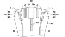
- FIG. 5 shows a side cross-sectional shape of the probe 311 of this embodiment.
- the width between the light emitting unit 40 and the transducer array 20 and the width between the other light emitting unit 40 and the transducer array 20 are slightly larger than the slit 45 in the probe 11 described above.
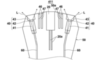
- FIG. 6 shows a side cross-sectional shape of the probe 411 of the present embodiment.
- the probe 411 is the same as that in the probe 311 of the third embodiment between one light emitting unit 40 and the transducer array 20 and between the other light emitting unit 40 and the transducer array 20.
- the two slits 47 are provided.
- the portions close to the respective housing surfaces 50a of the four slits 47 are filled with the same blocking member 46 as that in the second embodiment shown in FIG.
- Each blocking member 46 is arranged so that the surface thereof is flush with the housing surface 50 a and in close contact with the housing 50.
- the present embodiment can basically obtain the same operations and effects as those of the second embodiment.
- four interfaces of two materials having different acoustic impedances exist between one light emitting unit 40 and the transducer array 20. Therefore, when the photoacoustic wave generated in the vicinity of each light emitting portion 40 propagates through the blocking member 46 and travels toward the transducer array 20, the photoacoustic wave is transmitted four times at the interface as described above. Reflected and more attenuated. There are also four interfaces between the material of the housing 50 and air between one light emitting unit 40 and the transducer array 20.
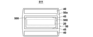
- FIG. 7 shows the front shape of the probe 511 of this embodiment.
- This probe 511 is the same as that in the probe 11 of the first embodiment between one light emitting unit 40 and the transducer array 20 and between the other light emitting unit 40 and the transducer array 20.
- the two slits 45 are provided.
- the two slits 45 are connected to each other by one slit and another slit 500 between the other ends. That is, the transducer array 20 is surrounded by the slit 45 and the slit 500 over the entire circumference.
- each light emitting portion 40 propagates outside the both end portions of the slit 45.
- the transducer array 20 is reached around the inside.
- the photoacoustic waves that wrap around as described above reach the transducer array 20. Is also prevented.
- the slit 500 may be discontinuous on the way.
- the photoacoustic image is generated and displayed using the probe 511 of the present embodiment, it is generated in the photoacoustic image as compared with the case where the photoacoustic image is generated and displayed using the probe 11 shown in FIG. Artifacts to do are reduced significantly.
- FIG. 8 shows a side cross-sectional shape of the probe 611 of the present embodiment.
- the material constituting the housing 50 is acoustic impedance between one light emitting unit 40 and the transducer array 20 and between the other light emitting unit 40 and the transducer array 20.
- a blocking member 48 made of a different material is disposed. Examples of such a combination of two materials include, but are not limited to, a material of the casing 50 made of ABS resin and a material of the blocking member 48 made of silicone rubber.
- the acoustic impedance of the former material is about 2.3 ⁇ 10 6 Pa ⁇ s / m
- the acoustic impedance of the latter material is 1.2 ⁇ 10 6 Pa ⁇ s / m to 1.5 ⁇ 10 6 Pa.
- -It is about s / m.
- the blocking member 48 is preferably made of a material having a high acoustic attenuation rate.
- the material of the blocking member 48 may be a foamed or porous plastic member.
- a combination of a plurality of members such as an upper part of the blocking member 48 such as silicone rubber and a lower part of the plastic member may be used. Since such a plastic member includes a large number of interfaces having different acoustic impedances inside, a further effect that photoacoustic waves are reflected and scattered within the member can be obtained.
- the surface of the blocking member 48 is arranged so as to be flush with the housing surface 50 a and in close contact with the housing 50.
- a blocking member 48 is provided with a slit similar to the slit 45 shown in FIG. 2 in the housing 50, and a material having an acoustic impedance different from that of the material constituting the housing 50 is applied to the slit. It can be created by filling over the depth.
- the housing 50 is made by, for example, injection molding, it can be made by embedding a material different from the housing material.
- the housing 50 after the housing 50 is created, it can be created by altering a part of the housing 50.
- the outer surface (on the light emitting unit 40 side) and the inner side (on the transducer array 20 side) of the blocking member 48 have interfaces where two materials having different acoustic impedances are in close contact with each other. These two interfaces extend from the housing surface 50a toward the inside of the housing. Therefore, as in the case where the blocking member 46 shown in FIG. 4 is provided, when a photoacoustic wave generated in the vicinity of one light emitting portion 40 attempts to travel toward the transducer array 20, the photoacoustic is obtained. Since the waves are reflected and attenuated at the two interfaces, respectively, the waves do not reach the transducer array 20 with high intensity. The same applies to the photoacoustic wave that occurs in the vicinity of another light emitting unit 40 and travels toward the transducer array 20.
- the blocking member 48 has both end portions outside the both end portions of the transducer array 20 with respect to the direction orthogonal to the arrangement direction of the light emitting portion 40 and the transducer array 20. Has been created to be located. Therefore, both ends of the interface between the blocking member 48 and the housing 50 are located outside the both ends of the transducer array 20. Therefore, the photoacoustic wave generated in the vicinity of each of both end portions of the light emitting unit 40 is reliably incident on this interface and reflected and attenuated.
- the blocking member 48 may be formed so as to surround the periphery of the transducer array 20 similarly to the slits 45 and 500 shown in FIG. In such a case, since the interface between the blocking member 48 and the casing 50 also surrounds the transducer array 20, the photoacoustic wave wraps around from the end side of the transducer array 20 and enters the transducer array 20. It is prevented from being detected. Note that the blocking member 48 newly disposed to surround the transducer array 20 (the blocking member 48 disposed at a position corresponding to the slit 500) may be discontinuous.
- FIG. 9 shows a side cross-sectional shape of the probe 711 of this embodiment.
- the probe 711 is different from the probe 611 of the sixth embodiment shown in FIG. 8 in that two blocking members 49 thinner than the blocking member 48 are provided instead of the one blocking member 48.
- These blocking members 49 are also made of a material having an acoustic impedance different from that of the material constituting the housing 50.
- the same operation and effect as those in the probe 611 of the sixth embodiment shown in FIG. 8 can be obtained.
- four interfaces of two materials having different acoustic impedances exist between one light emitting unit 40 and the transducer array 20. Therefore, when the photoacoustic wave generated in the vicinity of each light emitting portion 40 tries to travel toward the transducer array 20, the photoacoustic wave is reflected at the interface as described above four times in total and attenuated more greatly. Will come to do. Thereby, even when a photoacoustic image is generated and displayed using the probe 711 of this embodiment, occurrence of artifacts in the photoacoustic image is prevented.
- FIG. 10 shows a side cross-sectional shape of the probe 811 of this embodiment.
- the probe 811 is not provided with the blocking member 48, and instead, the housing 50 is composed of two types of materials 50 ⁇ / b> A and 50 ⁇ / b> B. It is different.
- the casing materials 50A and 50B have different acoustic impedances.
- the casing material 50A is used for a portion including the transducer array 20, and the casing material 50B is a light emitting portion on the outside of the material 50A. It is used for the part which contains 40.
- one interface between the two casing materials 50A and 50B having different acoustic impedances exists between one light emitting unit 40 and the transducer array 20. Therefore, when a photoacoustic wave generated in the vicinity of each light emitting portion 40 attempts to travel toward the transducer array 20, a part of the photoacoustic wave is reflected by the above-described interface and attenuates. . Thereby, even when a photoacoustic image is generated and displayed using the probe 811 of this embodiment, occurrence of artifacts in the photoacoustic image is prevented.
- the combination of the casing materials 50A and 50B include those in which the casing material 50A is ABS resin and the casing material 50B is acrylic resin, but the combination is not limited thereto.
- the acoustic impedance of the housing material 50A is about 2.3 ⁇ 10 6 Pa ⁇ s / m
- the acoustic impedance of the housing material 50B is about 3.2 ⁇ 10 6 Pa ⁇ s / m.
- the housing 50 is configured from the two housing materials 50A and 50B, a material having an acoustic impedance different from that of each housing material is disposed in the housing material 50A or the housing material 50B.
- the number of interfaces where two materials having different acoustic impedances are in close contact with each other can be further increased.
- the blocking member 48 as shown in FIG. 8 is disposed in the housing material 50B, three interfaces are present between the light emitting unit 40 and the transducer array 20.
- a slit may be provided at the boundary between the casing material 50A and the casing material 50B to insert another member. Moreover, when doing so, the slit may surround the transducer array 20. Furthermore, when the slit as described above is not provided, the boundary between the casing material 50A and the casing material 50B may be configured to surround the transducer array 20.
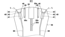
- FIG. 11 shows a side cross-sectional shape of the probe 911 of the present embodiment.
- This probe 911 is different from the probe 611 of the sixth embodiment shown in FIG. 8 in that the blocking member 46 is provided and the shape of the slit 50c of the housing 50 is different. More specifically, the blocking member 46 is fixed to the casing 50 so as to be flush with the casing surface 50a so as to cover the blocking member 48 from the probe surface side.
- the slit 50c that receives the blocking member 48 has a shape in which a plurality of irregularities that are serrated in the cross section and repeated in the slit depth direction are provided on the inner wall, that is, the wall surface on the transducer array 20 side.
- the blocking member 48 is Novec (registered trademark) 7100, which is a fluorinated solvent of 3M Company, or Fluorinert (registered trademark) FC-40, which is a fluorinated inert liquid of the same company.
- Novec 7100 is one of the hydrofluoroethers that are fluorinated liquids described above
- Fluorinert FC-40 is one of the perfluorocarbons that are also fluorinated liquids.
- the acoustic impedance is about 2.3 ⁇ 10 6 Pa ⁇ s / m as described above.
- the acoustic impedance of Novec 7100 is about 0.9 ⁇ 10 6 Pa ⁇ s / m
- the acoustic impedance of Fluorinert FC-40 is about 1.2 ⁇ 10 6 Pa ⁇ s / m. Therefore, also in the present embodiment, there are two interfaces where two materials having different acoustic impedances are in close contact with each other on the outer side (light emitting unit 40 side) and the inner side (vibrator array 20 side) of the blocking member 48. It is in a state extending from the body surface 50a toward the inside of the housing.
- the photoacoustic wave that is going to travel toward the transducer array 20 is scattered by these irregularities. Therefore, even if the photoacoustic wave reaches the transducer array 20, the photoacoustic wave is in a scattered state. From this point, the occurrence of the artifact is more reliably prevented.
- the subject M is generally a living body such as a human body. Since a living body usually contains a lot of water, the speed of sound in a living body at room temperature is about 1450 m / s to 1560 m / s in water. On the other hand, the sound speeds in the above-mentioned Novec7100 and Fluorinert FC-40 are 599.0 m / s and 636.4 m / s, respectively, which are about 40% of the sound speed in water.
- the probe 11 is configured as a hand-held type, the above-described depth of the slit 50c does not particularly lengthen the probe 11, and therefore the probe 11 has a reasonable size.
- the blocking member 48 is made of a general resin having an acoustic impedance different from that of the ABS resin mentioned above (for example, about 2.8 ⁇ 10 6 Pa ⁇ s / m).
- the speed of sound in the general resin is usually around 2000 m / s. Therefore, when the blocking member 48 is formed of such a general resin, if a photoacoustic image from the surface of the living body to a depth of 30 mm is generated as described above, a resin material thickness of about 40 mm is required. Become. The reason will be described below.
- an artifact generated from the probe housing 50 is displayed at a depth position of 30 mm or more from the living body surface in the photoacoustic wave image.
- the sound velocity V in the housing 50 is 2000 m / s as described above
- the observation time T of the photoacoustic wave generated at a depth of 30 mm from the living body surface and the equation (1) are used.
- the depth of the slit 50c needs to be about 40 mm.
- the probe 11 is configured as a hand-held type, if the depth of the slit 50c is required to be about 40 mm, the probe 11 becomes remarkably long for that reason, and it becomes very difficult to use as a hand-held type. .
- All of the probes according to the embodiments described above are formed by placing the transducer array 20 as an acoustic wave detection element in between and one light emitting section 40 on each side thereof.
- the probe is not limited to such a probe, and a probe in which a plurality of light emitting portions are disposed on at least one of both sides of one acoustic wave detecting element, or only one acoustic wave detecting element and one light emitting portion are provided.
- the present invention is also applicable to a probe having a plurality of acoustic wave detection elements.
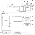
- FIG. 15 shows an example of the photoacoustic measuring apparatus 10 configured as described above.
- the photoacoustic measurement apparatus 10 shown in FIG. 15 has a configuration in which the data separation unit 23, the ultrasonic image generation unit 29, and the transmission control circuit 33 are removed as compared with the one shown in FIG.
- the photoacoustic measuring device 10 demonstrated above is comprised so that a photoacoustic image may be produced
- the probe of this invention is not restricted to that kind of photoacoustic measuring device, but detected photoacoustic
- the present invention is applicable to all photoacoustic measurement devices that perform some measurement based on waves. That is, if the probe of the present invention is applied to a photoacoustic measuring apparatus, it is widely prevented that the artifacts as described above adversely affect the measurement result.
Landscapes
- Health & Medical Sciences (AREA)
- Life Sciences & Earth Sciences (AREA)
- Physics & Mathematics (AREA)
- Engineering & Computer Science (AREA)
- General Health & Medical Sciences (AREA)
- Pathology (AREA)
- Molecular Biology (AREA)
- Veterinary Medicine (AREA)
- Public Health (AREA)
- Biophysics (AREA)
- Animal Behavior & Ethology (AREA)
- Biomedical Technology (AREA)
- Heart & Thoracic Surgery (AREA)
- Medical Informatics (AREA)
- Surgery (AREA)
- Signal Processing (AREA)
- Acoustics & Sound (AREA)
- Analytical Chemistry (AREA)
- Immunology (AREA)
- General Physics & Mathematics (AREA)
- Biochemistry (AREA)
- Chemical & Material Sciences (AREA)
- Psychiatry (AREA)
- Artificial Intelligence (AREA)
- Physiology (AREA)
- Computer Vision & Pattern Recognition (AREA)
- Nuclear Medicine, Radiotherapy & Molecular Imaging (AREA)
- Radiology & Medical Imaging (AREA)
- Optics & Photonics (AREA)
- Ultra Sonic Daignosis Equipment (AREA)
- Investigating Or Analyzing Materials By The Use Of Ultrasonic Waves (AREA)
Abstract
光音響計測装置においてアーチファクトの発生を防止できる光音響計測用プローブおよびプローブユニットを得る。測定光Lを被検体に向けて出射させる光出射部40と、測定光Lの照射を受けた被検体の部分から発せられた音響波を検出する音響波検出素子20と、使用時に被検体に向けられる表面50aを有し、内部に光出射部40および音響波検出素子20を収容した筐体50とを有する光音響計測用プローブ11において、光出射部40と音響波検出素子20との間に、筐体表面50aから筐体内部に向かって延びる、筐体表面50aに開口したスリット45を少なくとも1つ設ける。
Description
本発明は、被検体に向けて光を照射し、その光を受けて被検体内で発生した光音響波を検出する光音響計測用プローブに関するものである。
また本発明は、そのようなプローブを備えたプローブユニットおよび光音響計測装置に関するものである。
近年、光音響効果を利用した非侵襲の計測法が注目されている。この計測法は、ある適宜の波長(例えば、可視光、近赤外光または中間赤外光の波長帯域)を有するパルス光を被検体に照射し、被検体内の吸収物質がこのパルス光のエネルギーを吸収した結果生じる弾性波である光音響波を検出して、その吸収物質の濃度を定量的に計測するものである。被検体内の吸収物質とは、例えば血液中に含まれるグルコースやヘモグロビンなどである。また、このような光音響波を検出しその検出信号に基づいて光音響画像を生成する技術は、光音響イメージング(PAI:Photoacoustic Imaging)あるいは光音響トモグラフィー(PAT:Photo Acoustic Tomography)と呼ばれている。
光音響イメージングでは、例えば特許文献1および2に示されるように、パルス光等の測定光を被検体に向けて出射させる光出射部と、測定光の照射を受けた被検体の部分から発せられた音響波を検出する音響波検出素子と、内部に上記光出射部および音響波検出素子を収容した筐体とを備えてなるプローブが多く使用される。
従来、上記の光出射部、音響波検出素子および筐体を備えてなるプローブを用いて光音響画像を生成する場合、光音響画像にアーチファクト(偽画像)が発生しやすいことが認められている。
本発明は上記の事情に鑑みてなされたものであり、アーチファクトの発生を防止できる光音響計測用プローブを提供することを目的とする。
さらに本発明は、アーチファクトの発生を防止できるプローブユニットおよび光音響計測装置を提供することを目的とする。
本発明による一つの光音響計測用プローブは、
測定光を被検体に向けて出射させる光出射部と、
測定光の照射を受けた被検体の部分から発せられた音響波を検出する音響波検出素子と、
使用時に被検体に向けられる表面を有し、内部に光出射部および音響波検出素子を収容した筐体とを有する光音響計測用プローブにおいて、
光出射部と音響波検出素子との間に、筐体の表面から筐体内部に向かって延びる、筐体表面に開口したスリットを少なくとも1つ有することを特徴とするものである。
測定光を被検体に向けて出射させる光出射部と、
測定光の照射を受けた被検体の部分から発せられた音響波を検出する音響波検出素子と、
使用時に被検体に向けられる表面を有し、内部に光出射部および音響波検出素子を収容した筐体とを有する光音響計測用プローブにおいて、
光出射部と音響波検出素子との間に、筐体の表面から筐体内部に向かって延びる、筐体表面に開口したスリットを少なくとも1つ有することを特徴とするものである。
なお、上記構成を有する本発明の光音響計測用プローブにおいては、表面側から光音響計測用プローブを平面視した場合において、光出射部と音響波検出素子との並び方向と直交する方向に関して、スリットの両端部がそれぞれ、音響波検出素子の両端部よりも外側に位置していることが望ましい。
また、上記構成を有する本発明の光音響計測用プローブにおいては、音響波検出素子を間に置いて、音響波検出素子の両側に各々光出射部が少なくとも1つ配設されていることが望ましい。
そのように、音響波検出素子の両側に各々光出射部が少なくとも1つ配設されている場合は、音響波検出素子の両側に配設された光出射部の一方とこの音響波検出素子との間に配設されたスリットと、音響波検出素子の両側に配設された光出射部の他方とこの音響波検出素子との間に配設されたスリットとが、互いに一端部どうし、他端部どうしで別のスリットにより繋げられて、音響波検出素子がスリットにより囲まれていることが望ましい。なお、上記別のスリットは、途中で不連続となることが無いものとして、音響波検出素子がスリットにより全周に亘って囲まれるようにするのが望ましい。ただしそれに限らず、上記別のスリットは、途中で不連続とされていても構わない。
また、本発明による別の光音響計測用プローブは、
測定光を被検体に向けて出射させる光出射部と、
測定光の照射を受けた被検体の部分から発せられた音響波を検出する音響波検出素子と、
使用時に被検体に向けられる表面を有し、内部に光出射部および音響波検出素子を収容した筐体とを有する光音響計測用プローブにおいて、
互いに音響インピーダンスが異なる2つの材料を密接させてなる組であって、光出射部と音響波検出素子との間において筐体の表面から筐体内部に向かって延びる界面を構成する材料の組を、少なくとも1組有することを特徴とするものである。
測定光を被検体に向けて出射させる光出射部と、
測定光の照射を受けた被検体の部分から発せられた音響波を検出する音響波検出素子と、
使用時に被検体に向けられる表面を有し、内部に光出射部および音響波検出素子を収容した筐体とを有する光音響計測用プローブにおいて、
互いに音響インピーダンスが異なる2つの材料を密接させてなる組であって、光出射部と音響波検出素子との間において筐体の表面から筐体内部に向かって延びる界面を構成する材料の組を、少なくとも1組有することを特徴とするものである。
この本発明による別の光音響計測用プローブにおいては、表面側から光音響計測用プローブを平面視した場合において、光出射部と音響波検出素子との並び方向と直交する方向に関して、界面の両端部がそれぞれ、音響波検出素子の両端部よりも外側に位置していることが望ましい。
また、上述した本発明による別の光音響計測用プローブにおいては、音響波検出素子を間に置いて、この音響波検出素子の両側に各々光出射部が少なくとも1つ配設されていることが望ましい。
そのように、音響波検出素子の両側に各々光出射部が少なくとも1つ配設されている場合は、音響波検出素子の両側に配設された光出射部の一方とこの音響波検出素子との間に存在する界面と、音響波検出素子の両側に配設された光出射部の他方とこの音響波検出素子との間に存在する界面とが、互いに一端部どうし、他端部どうしで、互いに音響インピーダンスが異なる材料を密接させてなる別の界面により繋げられて、音響波検出素子が界面により囲まれていることが望ましい。なお、上記別の界面は、途中で不連続となることが無いものとして、音響波検出素子が界面により全周に亘って囲まれるようにするのが望ましい。ただしそれに限らず、上記別の界面は、途中で不連続とされていても構わない。
また、上述した本発明による別の光音響計測用プローブにおいては、光出射部と音響波検出素子との間に、筐体の表面から筐体内部に向かって延びるスリットが設けられ、このスリット内に、筐体を構成する材料とは音響インピーダンスが異なる材料が充填されていることが望ましい。
そのようにスリット内に、筐体を構成する材料とは音響インピーダンスが異なる材料が充填される場合は、筐体を構成する材料とは音響インピーダンスが異なる材料が、スリットの全深さに亘って充填されていることが望ましい。
あるいは、上記のスリット内に、筐体を構成する材料とは音響インピーダンスが異なる材料が充填される場合は、筐体を構成する材料とは音響インピーダンスが異なる材料が、筐体の表面と整合する位置から、スリットの深さよりも浅い位置までの間に充填されていてもよい。
なお、上述した筐体を構成する材料とは音響インピーダンスが異なる材料としては、例えばフッ素化液が好適に用いられる。この「フッ素化液」とは、パーフルオロポリエーテル類、パーフルオロカーボン類、ハイドロフロロポリエーテル類、ハイドロフルオロエーテル類のうちの一つ、もしくは複数からなる混合物から構成される液体を指すものである。
さらに、筐体を、光出射部を内包する部分と、音響波検出素子を内包する部分とで、互いに音響インピーダンスが異なる筐体材料から構成して、それら2つの筐体材料によって上記の界面を構成することも可能である。
他方、本発明によるプローブユニットは、
以上説明した本発明による光音響計測用プローブと、
測定光を出力する光源と、
測定光を光音響計測用プローブの光出射部へ光学的に接続する接続部とを備えてなるものである。
以上説明した本発明による光音響計測用プローブと、
測定光を出力する光源と、
測定光を光音響計測用プローブの光出射部へ光学的に接続する接続部とを備えてなるものである。
また、本発明による光音響計測装置は、
以上説明した本発明による光音響計測用プローブと、
光音響計測用プローブが出力する光音響波検出信号に基づいて光音響画像を生成する信号処理部とを備えてなるものである。
以上説明した本発明による光音響計測用プローブと、
光音響計測用プローブが出力する光音響波検出信号に基づいて光音響画像を生成する信号処理部とを備えてなるものである。
本発明者の研究によると、従来のプローブを用いた光音響計測装置においては、下記の原因によりアーチファクトが発生することが分かった。すなわち、プローブ筐体内の光出射部から測定光が出射する際、この測定光が筐体の表面近傍部分を照射することがある。すると、その測定光を吸収した筐体の部分から光音響波が発生し、この光音響波が音響波検出素子に検出されてアーチファクトが生じるのである。
本発明による一つの光音響計測用プローブにおいては、光出射部と音響波検出素子との間に、筐体の表面から筐体内部に向かって延びる、筐体表面に開口したスリットを少なくとも1つ有しているので、上述のように発生して音響波検出素子の方に進行する光音響波は、スリット内の空気と筐体材料との界面で反射、減衰する。そこで、高強度の光音響波が音響波検出素子に入射することがなくなって、アーチファクトの発生が防止される。
また、本発明による別の光音響計測用プローブにおいては、互いに音響インピーダンスが異なる2つの材料を密接させてなる組であって、光出射部と音響波検出素子との間において筐体の表面から筐体内部に向かって延びる界面を構成する材料の組を、少なくとも1組有しているので、上述のように発生して音響波検出素子の方に進行する光音響波は、上記界面で反射、減衰する。そこで、高強度の光音響波が音響波検出素子に入射することがなくなって、アーチファクトの発生が防止される。
以下、図面を参照して、本発明の実施形態について詳しく説明する。
<第1の実施形態>
まず、本発明の第1の実施形態による光音響計測プローブ、プローブユニットおよび光音響計測装置について説明する。図1は本実施形態の光音響計測装置10の全体構成を示す概略図であり、図2および図3はそれぞれ、上記光音響計測装置10に用いられた光音響計測プローブ(以下、単にプローブという)11を示す側断面図および正面図である。なお図1において、プローブ11の形状は概略的に示してある。
<第1の実施形態>
まず、本発明の第1の実施形態による光音響計測プローブ、プローブユニットおよび光音響計測装置について説明する。図1は本実施形態の光音響計測装置10の全体構成を示す概略図であり、図2および図3はそれぞれ、上記光音響計測装置10に用いられた光音響計測プローブ(以下、単にプローブという)11を示す側断面図および正面図である。なお図1において、プローブ11の形状は概略的に示してある。
本実施形態の光音響計測装置10は、一例として、光音響信号に基づいて光音響画像を生成する機能を有するものであり、図1に概略的に示すように、プローブ(超音波探触子)11、超音波ユニット12、レーザユニット13および表示部14等を備えている。以下、それらの構成要素について順次説明する。
プローブ11は、例えば生体である被検体Mに向けて測定光および超音波を照射する機能と、被検体M内を伝搬する音響波Uを検出する機能とを有する。すなわちプローブ11は、被検体Mに対する超音波の照射(送信)、および被検体Mで反射して戻って来た反射超音波(反射音響波)の検出(受信)を行うことができる。さらにプローブ11は、被検体M内で発生した光音響波も検出可能である。本明細書において「音響波」とは、超音波および光音響波を含む用語である。ここで、「超音波」とはプローブにより送信された弾性波およびその反射波を意味し、「光音響波」とは吸収体65が測定光を吸収することにより発する弾性波を意味する。なお被検体M内の吸収体65としては、例えば血管、金属部材等が挙げられる。
プローブ11は、図2に詳しく示される通り、音響波検出素子である振動子アレイ20と、この振動子アレイ20を間に置いて、該振動子アレイ20の両側に各々1つずつ配設された合計2つの光出射部40と、振動子アレイ20および2つの光出射部40を内部に収容した筐体50とを備えている。振動子アレイ20は、例えば、図2における上端面から約1mm程度内側に入ったところに位置する。
本実施形態において振動子アレイ20は、超音波送信素子としても機能する。振動子アレイ20は、配線20aを介して超音波送信用回路および音響波受信用回路と接続される。またプローブ11には、後述するレーザユニット13から発せられた測定光であるレーザ光Lを、光出射部40まで導光させる接続部としての光ファイバ60が接続されている。
上記振動子アレイ20は、例えば一次元または二次元に配列された複数の超音波振動子から構成されている。この超音波振動子は、例えば圧電セラミクス、またはポリフッ化ビニリデン(PVDF)のような高分子フィルムから構成された圧電素子である。超音波振動子は、受信した音響波Uを電気信号に変換する機能を有している。振動子アレイ20が出力する上記電気信号は、後述する受信回路21に入力される。プローブ11は一般に、セクタ走査対応のもの、リニア走査対応のもの、コンベックス走査対応のもの等が用意され、それらの中から適宜のものが撮像部位に応じて選択使用される。なお、振動子アレイ20は音響レンズを含んでもよい。
上記超音波振動子は、超音波を送信する機能も有する。すなわち、この超音波振動子に交番電圧が印加されると、超音波振動子は交番電圧の周波数に対応した周波数の超音波を発生させる。なお、超音波の送信と受信は互いに分離させてもよい。つまり、例えばプローブ11とは異なる位置から超音波の送信を行い、その送信された超音波に対する反射超音波をプローブ11で受信するようにしてもよい。
光出射部40は、光ファイバ60によって導光されたレーザ光Lを被検体Mに照射する部分である。図2および図3に示されるように、本実施形態では2つの光出射部40が、振動子アレイ20を間に置いて、振動子アレイ20の例えばエレベーション方向(複数の超音波振動子が一次元に配列された場合、その配列方向に直角で検出面に平行な方向)の両側に配置されている。
光出射部40は、一例として第1の導光部材41、拡散部42および第2の導光部材43から構成されている。第1の導光部材41、拡散部42および第2の導光部材43は、測定光の進行方向に対して直列に並べられており、これらは図示外の固定枠体によって固定されている。なお、第1の導光部材41は空気でもよい。
第1の導光部材41の光入射端面には、上述した光ファイバ60の光出射端面が光学的に結合されている。第1の導光部材41としては、例えば導光板を使用することができる。導光板は、例えばアクリル板や石英板の表面に特殊な加工が施されたものであり、一方の端面から入射した光を他方の端面から均一な面内強度で出射させる。この第1の導光部材41は、光ファイバ60によって導光されたレーザ光Lを拡散部42へ導光する。
拡散部42は、第1の導光部材41から出射したレーザ光Lを拡散させるものである。これにより、レーザ光Lの照射範囲がより拡大される。拡散部42としては、例えば拡散板を使用することができる。この拡散板としては、マイクロレンズが基板上にランダムに配置されているレンズ拡散板や、例えば拡散微粒子が分散された石英板等を使用することができる。レンズ拡散板としてはホログラフィック拡散板やエンジニアリング拡散板を用いてもよい。拡散部42は、第1の導光部材41と独立した部材である必要はない。例えば、第1の導光部材41の光出射端部に拡散層を設けて拡散部42としてもよいし、その光出射端面に拡散面を設けて拡散部42としてもよい。
拡散部42は、例えば接着剤によって図示外の固定部材に固定されるが、レンズ拡散板を接着する際には、光拡散性が強い接着剤を用いることが好ましい。これは、レンズ拡散面に接着剤が付着すると、その部分の光拡散性が失われ、局所的に強い光が出射する可能性があるためである。光拡散性を有する接着剤を用いた場合、レンズ拡散面に接着剤が付着した場合でも、接着剤の光拡散性によって光を拡散させることができる。接着剤としては、例えば白色顔料入りのシリコーンゴムなどの接着剤を用いることができる。白色顔料としては、例えばTiO2が挙げられる。TiO2の含有率は、1重量%~20重量%が好ましい。シリコーンゴムとしては、例えば信越化学工業株式会社製の液状ゴムKE-45-Wを用いることができる。
第2の導光部材43は、拡散部42によって拡散されたレーザ光Lを被検体Mに向けて出射させるものである。第2の導光部材43の光出射端部は、筺体50の光窓部(開口部分)に嵌められており、該光窓部の隙間を埋める機能を果たす。また、上述した拡散層や拡散面を第1の導光部材41に設ける代わりに、それぞれ第2の導光部材43の光入射端部や光入射端面に設けてもよい。
図1に示されるレーザユニット13は、例えばQスイッチアレキサンドライトレーザ等のフラッシュランプ励起Qスイッチ固体レーザを有し、被検体Mに照射する測定光としてのレーザ光Lを発する。レーザユニット13は、例えば超音波ユニット12の制御部34からのトリガ信号を受けてレーザ光Lを出力するように構成されている。レーザユニット13は、1~100nsec(ナノ秒)のパルス幅を有するパルスレーザ光Lを出力するものであることが好ましい。
レーザ光Lの波長は、計測の対象となる被検体M内の吸収体65の光吸収特性に応じて適宜選択される。例えば計測対象が生体内のヘモグロビンである場合、つまり血管を撮像する場合、一般的にその波長は、近赤外波長域に属する波長であることが好ましい。近赤外波長域とはおよそ700~850nmの波長域を意味する。しかし、レーザ光Lの波長は当然これに限られるものではない。またレーザ光Lは、単波長のものでもよいし、例えば750nmおよび800nm等の複数波長を含むものでもよい。レーザ光Lが複数の波長を含む場合、これらの波長の光は、同時に被検体Mに照射されてもよいし、交互に切り替えられながら照射されてもよい。
なおレーザユニット13は、上に述べたアレキサンドライトレーザの他、同様に近赤外波長域のレーザ光を出力可能なYAG-SHG(Second harmonic generation:第二次高調波発生)-OPO(Optical Parametric Oscillation:光パラメトリック発振)レーザや、Ti-Sapphire(チタン-サファイア)レーザ等を用いて構成することもできる。
光源としての上記レーザユニット13は、プローブ11および光ファイバ60と共にプローブユニットを構成している。
光ファイバ60は、レーザユニット13から出射されたレーザ光Lを、2つの光出射部40まで導く。光ファイバ60は特に限定されず、石英ファイバ等の公知のものを使用することができる。例えば1本の太い光ファイバが用いられてもよいし、あるいは複数の光ファイバが束ねられてなるバンドルファイバが用いられてもよい。一例としてバンドルファイバが用いられる場合、1つにまとめられたファイバ部分の光入射端面から上記レーザ光Lが入射するようにバンドルファイバが配置され、そしてバンドルファイバの2つに分岐されたファイバ部分の光出射端面にそれぞれ光出射部40が結合される。
超音波ユニット12は、受信回路21、受信メモリ22、データ分離手段23、光音響画像生成部24、超音波画像生成部29、表示制御部30、送信制御回路33および制御部34を有する。
制御部34は、光音響計測装置10の各部を制御するものであり、本実施形態では図示外のトリガ制御回路を備える。このトリガ制御回路は、例えば光音響画像を取得する場合には、レーザユニット13に光トリガ信号を送る。これによりレーザユニット13のQスイッチ固体レーザにおいて励起源のフラッシュランプが点灯し、レーザロッドの励起が開始される。このレーザロッドの励起状態が維持されている間、レーザユニット13はレーザ光Lを出力可能な状態となる。
制御部34は、その後トリガ制御回路からレーザユニット13へQスイッチトリガ信号を送信する。つまり制御部34は、このQスイッチトリガ信号によって、レーザユニット13からのレーザ光Lの出力タイミングを制御する。また制御部34は、Qスイッチトリガ信号の送信と同時に、サンプリングトリガ信号を受信回路21に送信する。このサンプリングトリガ信号は、受信回路21のAD変換器(Analog to Digital convertor)における光音響信号のサンプリングの開始タイミングを規定する。このように、サンプリングトリガ信号を使用することにより、レーザ光Lの出力と同期して光音響信号をサンプリングすることが可能となる。
制御部34は、超音波画像を取得する場合は、送信制御回路33に超音波送信を指示する超音波送信トリガ信号を送信する。送信制御回路33は、超音波送信トリガ信号を受けると、プローブ11から超音波を送信させる。制御部34は、超音波送信のタイミングに合わせて受信回路21にサンプリングトリガ信号を送信し、反射超音波信号のサンプリングを開始させる。
以上述べた光音響画像あるいは超音波画像を取得する際、プローブ11は、被検体Mに対して例えば前述したエレベーション方向に少しずつ位置が変えられて、レーザ光Lあるいは超音波により被検体Mが走査される。そこで上記光音響信号あるいは反射超音波信号のサンプリングはこの走査と同期して、音響波検出ラインを一ラインずつずらしながらなされる。なお上記走査は、術者がプローブ11を手操作で動かすことによってなされてもよいし、あるいは自動走査機構を用いてなされてもよい。
受信回路21は、プローブ11が出力する検出信号を受信し、受信した検出信号を受信メモリ22に格納する。受信回路21は典型的には、低ノイズアンプ、可変ゲインアンプ、ローパスフィルタ、およびAD変換器を含んで構成される。プローブ11の検出信号は、低ノイズアンプで増幅された後に、可変ゲインアンプで深度に応じたゲイン調整がなされ、ローパスフィルタで高周波成分がカットされた後にAD変換器でデジタル信号に変換され、受信メモリ22に格納される。受信回路21は、例えば1つのIC(Integrated Circuit)で構成される。
本実施形態においてプローブ11は、光音響波の検出信号と反射超音波の検出信号とを出力する。そこで受信メモリ22には、デジタル化された光音響波および反射超音波の検出信号(サンプリングデータ)が格納される。データ分離手段23は、受信メモリ22から光音響波検出信号のサンプリングデータ(光音響データ)を読み出して、光音響画像生成部24に送信する。またデータ分離手段23は、受信メモリ22から反射超音波検出信号のサンプリングデータ(反射超音波データ)を読み出して、超音波画像生成部29に送信する。
光音響画像生成部24は、受信メモリ22に格納された上記光音響データを、プローブ11の振動子アレイ20の位置に応じた遅延時間で互いに加算して1ライン分のデータを再構成し、各ラインの光音響データに基づいて断層画像(光音響画像)のデータを生成する。なお、この光音響画像生成部24は、遅延加算法に代えて、CBP法(Circular Back Projection)により再構成を行うものでもよい。あるいは光音響画像生成部24は、ハフ変換法またはフーリエ変換法を用いて再構成を行うものでもよい。光音響画像生成部24は、上記のようにして生成された光音響画像のデータを表示制御部30に出力する。
以上の説明から明らかな通り、光音響画像生成部24は、本発明の光音響計測装置における信号処理部を構成している。
超音波画像生成部29は、受信メモリ22に格納された反射超音波データに対して、基本的に上記光音響データに対するのと同様の処理を施して、断層画像(超音波画像)のデータを生成する。超音波画像生成部29は、そのようにして生成された超音波画像のデータを表示制御部30に出力する。
表示制御部30は、上記光音響画像のデータに基づいて光音響画像を、また上記超音波画像のデータに基づいて超音波画像を、それぞれ表示部14に表示させる。これら2つの画像は別々に、あるいは合成されて合成画像として表示部14に表示される。後者の場合、表示制御部30は、例えば光音響画像と超音波画像とを重畳させて画像合成を行う。このように、光音響画像に加えて超音波画像を生成、表示させれば、光音響画像では画像化することができない部分を超音波画像において観察可能となる。
次に、以上述べた通りの基本構成を有する光音響計測装置10において、アーチファクトの発生を防止するためにプローブ11が有する構成について説明する。図2および図3に示される通りプローブ11には、振動子アレイ20と一方の光出射部40との間、および振動子アレイ20と他方の光出射部40との間に、スリット45が設けられている。各スリット45は、筐体50の表面50aから筐体内部に向かって延び、そして筐体表面50aに開口するような形とされている。
ここで図12に、上述したようなスリット45を有していない従来のプローブの例を示す。図12は、そのプローブの側断面形状を示すものである。なおこの図12において、先に説明した図2中のものと同等の要素には同番号を付してあり、それらについての説明は特に必要の無い限り省略する(以下、同様)。本発明者の研究によると、従来のプローブを用いた光音響計測装置においては、下記の原因によりアーチファクトが発生し得ることが分かった。すなわち、図12に示すように光出射部40から測定光(レーザ光)Lが出射する際、この測定光Lが筐体50の表面近傍部分を照射することがある。すると、その測定光Lを吸収した筐体50の部分から、同図に矢印Aで概略的に示すように光音響波が発生し、この光音響波が振動子アレイ20に検出されてアーチファクトが生じるのである。
本発明の光音響計測用プローブは、上記の新しい知見に基づいて得られたものである。具体的に本実施形態のプローブ11においては、振動子アレイ20と光出射部40との間に設けたスリット45により、上述のようにして発生した光音響波を減衰させるようにしている。つまり、1つのスリット45の2つの側面(振動子アレイ20側の側面と、光出射部40側の側面)の所では、スリット内の空気と筐体50の材料とが接する状態になっていて、それら両者は音響インピーダンスが互いに大きく異なっている。したがって、1つの光出射部40の近傍で発生して振動子アレイ20の方に進行する光音響波は、このスリット45の2つの側面の所で反射、減衰するようになる。そのため、高強度の光音響波が振動子アレイ20に到達することがなくなる。これは、別の光出射部40の近傍で発生して、振動子アレイ20の方に進行する光音響波に関しても同様である。
なお具体的に、空気の音響インピーダンスは440Pa・s/m程度、筐体50の材料が例えばABS(アクリロニトリルブタジエンスチレン共重合合成樹脂)の場合、その音響インピーダンスは2.3×106Pa・s/m程度である。
以上の通りにして、本実施形態のプローブ11を用いて光音響画像を生成、表示させる場合は、光音響画像にアーチファクトが発生することが防止される。
図13および図14は、以上述べたことを、実際に光音響画像(断層画像)を生成、表示させて確認した結果を示すものである。図13は、スリット45が設けられていない以外は本実施形態のプローブ11と同等の構成を有する従来のプローブを用いて生成された光音響画像を示す写真、図14は本実施形態のプローブ11を用いて生成された光音響画像を示す写真である。なおこれらの光音響画像は共に強調処理を施したバックグラウンド画像であり、各図の左側に示した数字は、プローブ表面からの距離つまり被写体の深さ位置を示している。図13の画像では、深さ位置が10mmに近いところから20mmの位置までに亘って横縞状のアーチファクトが認められるのに対し、図14画像ではそのような明らかなアーチファクトは認められない。
なお本実施形態のプローブ11においては、図3に明確に示されるように、各スリット45の長さは、振動子アレイ20の長さよりも大とされている。つまり、プローブ11を表面(正面)から平面視した場合において、光出射部40と振動子アレイ20との並び方向と直交する方向(図3中の左右方向)に関して、スリット45の両端部がそれぞれ、振動子アレイ20の両端部よりも外側に位置している。このような構成とすることにより、光出射部40の側端部に近い所で発生した光音響波も、スリット45に確実に入射して減衰するようになる。
<第2の実施形態>
次に図4を参照して、本発明の第2の実施形態によるプローブ211について説明する。図4は、本実施形態のプローブ211の側断面形状を示すものである。このプローブ211においても、前述したプローブ11におけるのと同様の2つのスリット45が設けられている。そして各スリット45の筐体表面50aに近い部分には、遮断部材46が充填されている。各遮断部材46は、その表面が筐体表面50aと面一に整合し、また、筐体50と密接する状態に配置されている。このような遮断部材46を配しておくことにより、スリット45内に異物等が侵入することを防止できる。
次に図4を参照して、本発明の第2の実施形態によるプローブ211について説明する。図4は、本実施形態のプローブ211の側断面形状を示すものである。このプローブ211においても、前述したプローブ11におけるのと同様の2つのスリット45が設けられている。そして各スリット45の筐体表面50aに近い部分には、遮断部材46が充填されている。各遮断部材46は、その表面が筐体表面50aと面一に整合し、また、筐体50と密接する状態に配置されている。このような遮断部材46を配しておくことにより、スリット45内に異物等が侵入することを防止できる。
遮断部材46は、筐体50の材料とは音響インピーダンスが異なる材料からなるものである。そのような2つの材料の組み合わせとしては、筐体50の材料をABS樹脂とし、遮断部材46の材料をシリコーンゴムとするものが例示されるが、それに限られるものではない。上記例において、前者の材料の音響インピーダンスは2.3×10⁶Pa・s/
m程度、後者の材料の音響インピーダンスは1.2×10⁶Pa・s/m~1.5×106Pa・s/m程度である。なお、遮断部材46は音響減衰率の高い材料であることが望ましい。
m程度、後者の材料の音響インピーダンスは1.2×10⁶Pa・s/m~1.5×106Pa・s/m程度である。なお、遮断部材46は音響減衰率の高い材料であることが望ましい。
以上の構成を有する本実施形態のプローブ211においては、スリット45の、遮断部材46が存在していない部分により、第1の実施形態のプローブ11におけるのと同様にして、光音響波が反射、減衰する。
またそれに加えて、スリット45の、遮断部材46が存在している部分においても、上記光音響波を減衰させる効果が得られる。すなわち、各遮断部材46の両端部(振動子アレイ20側の端部と、光出射部40側の端部)には、音響インピーダンスが互いに異なる2つの材料が密接してなる界面がそれぞれ存在している。これら2つの界面は、筐体表面50aから筐体内部に向かって延びる状態となっている。したがって、1つの光出射部40の近傍で発生した光音響波が、遮断部材46を伝搬して振動子アレイ20の方に進行しようとすると、その光音響波は上記2つの界面でそれぞれ反射して減衰するので、高強度で振動子アレイ20まで到達することがなくなる。これは、別の光出射部40の近傍で発生して、振動子アレイ20の方に進行する光音響波に関しても同様である。
以上の通りにして、本実施形態のプローブ211を用いて光音響画像を生成、表示させる場合も、光音響画像にアーチファクトが発生することが防止される。なお、図4に示されている遮断部材46から見てスリット側の内部に、詳細には図4に示されている遮断部材46の下部に、発泡状あるいは多孔質形状のプラスチック部材があっても良い。このようなプラスチック部材は内部に音響インピーダンスが異なる界面を多数含むため、部材内で光音響波が反射および散乱するという更なる効果も得られる。
<第3の実施形態>
次に図5を参照して、本発明の第3の実施形態によるプローブ311について説明する。図5は、本実施形態のプローブ311の側断面形状を示すものである。このプローブ311においては、一方の光出射部40と振動子アレイ20との間、および他方の光出射部40と振動子アレイ20との間にそれぞれ、前述したプローブ11におけるスリット45よりはやや幅が小さい2つのスリット47が設けられている。このような2つのスリット47も、前述したスリット45と同様に、各光出射部40の近傍で発生して振動子アレイ20の方に向かって進行する光音響波を反射、減衰させる。それにより、本実施形態のプローブ311を用いて光音響画像を生成、表示させる場合も、光音響画像にアーチファクトが発生することが防止される。
次に図5を参照して、本発明の第3の実施形態によるプローブ311について説明する。図5は、本実施形態のプローブ311の側断面形状を示すものである。このプローブ311においては、一方の光出射部40と振動子アレイ20との間、および他方の光出射部40と振動子アレイ20との間にそれぞれ、前述したプローブ11におけるスリット45よりはやや幅が小さい2つのスリット47が設けられている。このような2つのスリット47も、前述したスリット45と同様に、各光出射部40の近傍で発生して振動子アレイ20の方に向かって進行する光音響波を反射、減衰させる。それにより、本実施形態のプローブ311を用いて光音響画像を生成、表示させる場合も、光音響画像にアーチファクトが発生することが防止される。
<第4の実施形態>
次に図6を参照して、本発明の第4の実施形態によるプローブ411について説明する。図6は、本実施形態のプローブ411の側断面形状を示すものである。このプローブ411においては、一方の光出射部40と振動子アレイ20との間、および他方の光出射部40と振動子アレイ20との間にそれぞれ第3の実施形態のプローブ311におけるものと同様の2つのスリット47が設けられている。そして合計4つのスリット47のそれぞれの筐体表面50aに近い部分に、図4に示した第2の実施形態におけるものと同様の遮断部材46が充填されている。各遮断部材46は、その表面が筐体表面50aと面一に整合し、また、筐体50と密接する状態に配置されている。
次に図6を参照して、本発明の第4の実施形態によるプローブ411について説明する。図6は、本実施形態のプローブ411の側断面形状を示すものである。このプローブ411においては、一方の光出射部40と振動子アレイ20との間、および他方の光出射部40と振動子アレイ20との間にそれぞれ第3の実施形態のプローブ311におけるものと同様の2つのスリット47が設けられている。そして合計4つのスリット47のそれぞれの筐体表面50aに近い部分に、図4に示した第2の実施形態におけるものと同様の遮断部材46が充填されている。各遮断部材46は、その表面が筐体表面50aと面一に整合し、また、筐体50と密接する状態に配置されている。
上記のようなスリット47を設けると共に遮断部材46を配しておくことにより、本実施形態でも、基本的に、第2の実施形態におけるのと同様の作用、効果が得られる。本実施形態では特に、1つの光出射部40と振動子アレイ20との間に、互いに音響インピーダンスが異なる2つの材料の界面が4つ存在している。そこで、各光出射部40の近傍で発生した光音響波が、遮断部材46を伝搬して振動子アレイ20の方に進行しようとすると、その光音響波は上記のような界面で合計4回反射して、より大きく減衰するようになる。また、1つの光出射部40と振動子アレイ20との間に、筐体50の材料と空気との界面も4つ存在している。そこで、これらの界面における光音響波の反射、減衰もより大きいものとなる。それにより、本実施形態のプローブ411を用いて光音響画像を生成、表示させる場合も、光音響画像にアーチファクトが発生することが防止される。
<第5の実施形態>
次に図7を参照して、本発明の第5の実施形態によるプローブ511について説明する。図7は、本実施形態のプローブ511の正面形状を示すものである。このプローブ511においては、一方の光出射部40と振動子アレイ20との間、および他方の光出射部40と振動子アレイ20との間にそれぞれ第1の実施形態のプローブ11におけるものと同様の2つのスリット45が設けられている。そしてこれら2つのスリット45は、互いに一端部どうし、他端部どうしで別のスリット500により繋げられている。つまり振動子アレイ20は、全周に亘ってスリット45及びスリット500により囲まれている状態となっている。
次に図7を参照して、本発明の第5の実施形態によるプローブ511について説明する。図7は、本実施形態のプローブ511の正面形状を示すものである。このプローブ511においては、一方の光出射部40と振動子アレイ20との間、および他方の光出射部40と振動子アレイ20との間にそれぞれ第1の実施形態のプローブ11におけるものと同様の2つのスリット45が設けられている。そしてこれら2つのスリット45は、互いに一端部どうし、他端部どうしで別のスリット500により繋げられている。つまり振動子アレイ20は、全周に亘ってスリット45及びスリット500により囲まれている状態となっている。
図3に示したような構成においては、各光出射部40の両端部(図3中の左右端部)近傍部分で発生した光音響波が、スリット45の両端部の外側を伝搬してから内側に回り込んで振動子アレイ20に到達する可能性もある。それに対して、本実施形態におけるように振動子アレイ20がスリット45、500によって囲まれている状態になっていれば、上述のように回り込んだ光音響波が振動子アレイ20に到達することも防止される。なお、上記スリット500は、途中で不連続とされていても構わない。
そこで、本実施形態のプローブ511を用いて光音響画像を生成、表示させる場合は、図3に示したプローブ11を用いて光音響画像を生成、表示させる場合と比べて、光音響画像に発生するアーチファクトはより顕著に低減する。
<第6の実施形態>
次に図8を参照して、本発明の第6の実施形態によるプローブ611について説明する。図8は、本実施形態のプローブ611の側断面形状を示すものである。このプローブ611においては、一方の光出射部40と振動子アレイ20との間、および他方の光出射部40と振動子アレイ20との間にそれぞれ、筐体50を構成する材料とは音響インピーダンスが異なる材料からなる遮断部材48が配設されている。そのような2つの材料の組み合わせとしては、筐体50の材料をABS樹脂とし、遮断部材48の材料をシリコーンゴムとするものが例示されるが、それに限られるものではない。上記例において、前者の材料の音響インピーダンスは2.3×10⁶Pa・s/m程度、後者の材料の音響インピーダンスは1.2×106Pa・s/m~1.5×106Pa・s/m程度である。なお、遮断部材48は、音響減衰率の高い材料であることが望ましい。なお、遮断部材48の材料としては、発泡状あるいは多孔質形状のプラスチック部材でも良い。また、遮断部材48の上部がシリコーンゴムで下部がプラスチック部材のような複数部材の組み合わせでも良い。このようなプラスチック部材は内部に音響インピーダンスが異なる界面を多数含むため、部材内で光音響波が反射および散乱するという更なる効果も得られる。
次に図8を参照して、本発明の第6の実施形態によるプローブ611について説明する。図8は、本実施形態のプローブ611の側断面形状を示すものである。このプローブ611においては、一方の光出射部40と振動子アレイ20との間、および他方の光出射部40と振動子アレイ20との間にそれぞれ、筐体50を構成する材料とは音響インピーダンスが異なる材料からなる遮断部材48が配設されている。そのような2つの材料の組み合わせとしては、筐体50の材料をABS樹脂とし、遮断部材48の材料をシリコーンゴムとするものが例示されるが、それに限られるものではない。上記例において、前者の材料の音響インピーダンスは2.3×10⁶Pa・s/m程度、後者の材料の音響インピーダンスは1.2×106Pa・s/m~1.5×106Pa・s/m程度である。なお、遮断部材48は、音響減衰率の高い材料であることが望ましい。なお、遮断部材48の材料としては、発泡状あるいは多孔質形状のプラスチック部材でも良い。また、遮断部材48の上部がシリコーンゴムで下部がプラスチック部材のような複数部材の組み合わせでも良い。このようなプラスチック部材は内部に音響インピーダンスが異なる界面を多数含むため、部材内で光音響波が反射および散乱するという更なる効果も得られる。
上記遮断部材48は、その表面が筐体表面50aと面一に整合し、また、筐体50と密接する状態に配置されている。このような遮断部材48は例えば、図2に示したスリット45と同様のスリットを筐体50に設けた後、そのスリットに、筐体50を構成する材料とは音響インピーダンスが異なる材料をスリット全深さに亘って充填することにより作成することができる。あるいは、筐体50を例えば射出成形によって作る際に、筐体材料とは別の材料を埋め込むことによって作成することもできる。さらには、筐体50を作成した後に、該筐体50の一部を変質させることによって作成することもできる。
上記遮断部材48の外側(光出射部40側)と内側(振動子アレイ20側)には、音響インピーダンスが互いに異なる2つの材料が密接してなる界面がそれぞれ存在している。これら2つの界面は、筐体表面50aから筐体内部に向かって延びる状態となっている。そこで、図4に示した遮断部材46が設けられている場合と同様に、1つの光出射部40の近傍で発生した光音響波が振動子アレイ20の方に進行しようとすると、その光音響波は上記2つの界面でそれぞれ反射、減衰するので、高強度で振動子アレイ20まで到達することがなくなる。これは、別の光出射部40の近傍で発生して、振動子アレイ20の方に進行する光音響波に関しても同様である。
以上により、本実施形態のプローブ611を用いて光音響画像を生成、表示させる場合も、光音響画像にアーチファクトが発生することが防止される。
なお遮断部材48は、図2に示したスリット45と同様に、光出射部40と振動子アレイ20との並び方向と直交する方向に関して、両端部がそれぞれ振動子アレイ20の両端部よりも外側に位置するように作成されている。したがって、この遮断部材48と筐体50との界面も、両端部がそれぞれ振動子アレイ20の両端部よりも外側に位置する状態となっている。そこで、光出射部40の両端部の各々の近傍で発生した光音響波もこの界面に確実に入射して反射、減衰するようになる。
また遮断部材48は、図7に示したスリット45および500と同様に、振動子アレイ20の周囲を囲むように作成されてもよい。そうした場合は、遮断部材48と筐体50との界面も振動子アレイ20の周囲を囲む状態となるので、光音響波が振動子アレイ20の端部側から回り込んで該振動子アレイ20に検出されることが防止される。なお、振動子アレイ20の周囲を囲むために新たに配設する遮断部材48(スリット500に相当する位置に配する遮断部材48)は、途中で不連続とされていても構わない。
<第7の実施形態>
次に図9を参照して、本発明の第7の実施形態によるプローブ711について説明する。図9は、本実施形態のプローブ711の側断面形状を示すものである。このプローブ711は、図8に示した第6実施形態のプローブ611と比べると、1つの遮断部材48の代わりに、それよりも薄い2つの遮断部材49が設けられている点で異なる。それらの遮断部材49も、筐体50を構成する材料とは音響インピーダンスが異なる材料からなるものである。
次に図9を参照して、本発明の第7の実施形態によるプローブ711について説明する。図9は、本実施形態のプローブ711の側断面形状を示すものである。このプローブ711は、図8に示した第6実施形態のプローブ611と比べると、1つの遮断部材48の代わりに、それよりも薄い2つの遮断部材49が設けられている点で異なる。それらの遮断部材49も、筐体50を構成する材料とは音響インピーダンスが異なる材料からなるものである。
上記構成のプローブ711においても、図8に示した第6実施形態のプローブ611におけるのと同様の作用、効果が得られる。本実施形態では特に、1つの光出射部40と振動子アレイ20との間に、互いに音響インピーダンスが異なる2つの材料の界面が4つ存在している。そこで、各光出射部40の近傍で発生した光音響波が、振動子アレイ20の方に進行しようとすると、その光音響波は上記のような界面で合計4回反射して、より大きく減衰するようになる。それにより、本実施形態のプローブ711を用いて光音響画像を生成、表示させる場合も、光音響画像にアーチファクトが発生することが防止される。
<第8の実施形態>
次に図10を参照して、本発明の第8の実施形態によるプローブ811について説明する。図10は、本実施形態のプローブ811の側断面形状を示すものである。このプローブ811は、図8に示した第6実施形態のプローブ611と比べると、遮断部材48が設けられず、その代わりに、筐体50が2種の材料50Aおよび50Bから構成されている点で異なる。それらの筐体材料50Aおよび50Bは、互いに音響インピーダンスが異なるものであり、筐体材料50Aは振動子アレイ20を内包する部分に用いられ、筐体材料50Bは材料50Aの外側でそれぞれ光出射部40を内包する部分に用いられている。
次に図10を参照して、本発明の第8の実施形態によるプローブ811について説明する。図10は、本実施形態のプローブ811の側断面形状を示すものである。このプローブ811は、図8に示した第6実施形態のプローブ611と比べると、遮断部材48が設けられず、その代わりに、筐体50が2種の材料50Aおよび50Bから構成されている点で異なる。それらの筐体材料50Aおよび50Bは、互いに音響インピーダンスが異なるものであり、筐体材料50Aは振動子アレイ20を内包する部分に用いられ、筐体材料50Bは材料50Aの外側でそれぞれ光出射部40を内包する部分に用いられている。
上記構成のプローブ811においては、1つの光出射部40と振動子アレイ20との間に、互いに音響インピーダンスが異なる2つの筐体材料50Aおよび50Bの界面が1つ存在している。そこで、各光出射部40の近傍で発生した光音響波が、振動子アレイ20の方に進行しようとすると、その光音響波の一部は上記の界面で反射して、減衰するようになる。それにより、本実施形態のプローブ811を用いて光音響画像を生成、表示させる場合も、光音響画像にアーチファクトが発生することが防止される。
上記筐体材料50Aおよび50Bの組み合わせとして具体的には、筐体材料50AをABS樹脂とし、筐体材料50Bをアクリル樹脂とするものが例示されるが、それに限られるものではない。なお上記例において、筐体材料50Aの音響インピーダンスは2.3×10⁶Pa・s/m程度、筐体材料50Bの音響インピーダンスは3.2×106Pa・s/m程度である。
上述したように2つの筐体材料50Aおよび50Bから筐体50を構成する場合も、筐体材料50Aまたは筐体材料50Bの中に、各筐体材料とは音響インピーダンスが異なる材料を配設して、互いに音響インピーダンスが異なる2つの材料が密接してなる界面の数をさらに増やすこともできる。例えば、筐体材料50Bの中に、図8に示したような遮断部材48を配設すれば、光出射部40と振動子アレイ20との間に上記界面が3つ存在することになる。
なお、筐体材料50Aと筐体材料50Bとの境界にスリットを設けて別の部材を入れてもよい。また、そのようにする場合、そのスリットが振動子アレイ20を囲むように構成されてもよい。さらに、上述のようなスリットを設けない場合において、筐体材料50Aと筐体材料50Bとの境界が、振動子アレイ20を囲むように構成されてもよい。
<第9の実施形態>
次に図11を参照して、本発明の第9の実施形態によるプローブ911について説明する。図11は、本実施形態のプローブ911の側断面形状を示すものである。このプローブ911は、図8に示した第6実施形態のプローブ611と比べると、遮断部材46が設けられている点、および筐体50のスリット50cの形状の点で異なるものである。より詳しくは、上記遮断部材46は、遮断部材48をプローブ表面側から覆うように筐体表面50aと面一にして筐体50に固定されている。また、遮断部材48を受け入れているスリット50cは、その内側つまり振動子アレイ20側の壁面に、断面鋸歯状でスリット深さ方向に繰り返す複数の凹凸が設けられた形状とされている。
次に図11を参照して、本発明の第9の実施形態によるプローブ911について説明する。図11は、本実施形態のプローブ911の側断面形状を示すものである。このプローブ911は、図8に示した第6実施形態のプローブ611と比べると、遮断部材46が設けられている点、および筐体50のスリット50cの形状の点で異なるものである。より詳しくは、上記遮断部材46は、遮断部材48をプローブ表面側から覆うように筐体表面50aと面一にして筐体50に固定されている。また、遮断部材48を受け入れているスリット50cは、その内側つまり振動子アレイ20側の壁面に、断面鋸歯状でスリット深さ方向に繰り返す複数の凹凸が設けられた形状とされている。
本実施形態において、遮断部材48としては、3M社(3M Company)のフッ素系溶剤であるNovec(登録商標)7100や、あるいは同社のフッ素系不活性液体であるフロリナート(登録商標)FC-40が好適に用いられる。なお、Novec7100は、前述したフッ素化液であるハイドロフルオロエーテル類の一つ、フロリナートFC-40は同じくフッ素化液であるパーフルオロカーボン類の一つである。このように遮断部材48がフッ素化液からなるものとされていても、上記遮断部材46が設けられているので、遮断部材48が筐体50から漏出することはない。
筐体50の材料をABS樹脂とすると、その音響インピーダンスは前述したように2.3×10⁶Pa・s/m程度である。それに対して、Novec7100の音響インピーダンスは0.9×106Pa・s/m、フロリナートFC-40の音響インピーダンスは~1.2×106Pa・s/m程度である。したがって本実施形態においても、遮断部材
48の外側(光出射部40側)と内側(振動子アレイ20側)においてそれぞれ、音響インピーダンスが互いに異なる2つの材料が密接してなる界面が2つ、筐体表面50aから筐体内部に向かって延びた状態となっている。
48の外側(光出射部40側)と内側(振動子アレイ20側)においてそれぞれ、音響インピーダンスが互いに異なる2つの材料が密接してなる界面が2つ、筐体表面50aから筐体内部に向かって延びた状態となっている。
そこで、本実施形態においても、1つの光出射部40の近傍で発生した光音響波が振動子アレイ20の方に進行しようとすると、その光音響波は上記2つの界面でそれぞれ反射、減衰するので、高強度で振動子アレイ20まで到達することがなくなる。これは、別の光出射部40の近傍で発生して、振動子アレイ20の方に進行する光音響波に関しても同様である。以上により、本実施形態のプローブ911を用いて光音響画像を生成、表示させる場合も、光音響画像にアーチファクトが発生することが防止される。
さらに本実施形態では、スリット50cの壁面に前述した複数の凹凸が設けられているので、振動子アレイ20の方に進行しようとする光音響波は、これらの凹凸によって散乱される。したがって、上記光音響波がたとえ振動子アレイ20に到達したとしても、散乱した状態となっているので、この点から、上記アーチファクトの発生がより確実に防止される。
なお、被検体Mは一般に、人体等の生体である。生体には通常、水が多く含まれるので、常温下の生体中での音速は、水中での音速1450m/s~1560m/sと同程度となっている。それに対して、上に挙げたNovec7100、フロリナートFC-40の中での音速は各々599.0m/s、636.4m/sであって、水中の音速の40%程度である。そのため、例えば生体表面から30mmの深さまでの光音響画像を生成して観察したい場合、遮断部材48を充填させるスリット50cは、筐体表面50aから12mm(=30mm×0.4)程度の深さとすればよい。プローブ11をハンドヘルド型のものとして構成する場合、上記程度のスリット50cの深さはプローブ11を特に長大化させるものではなく、よって、プローブ11は妥当なサイズのものとなる。
それに対して、上に挙げたABS樹脂とは音響インピーダンスが異なる(例えば2.8×10⁶Pa・s/m程度)一般的な樹脂から遮断部材48を構成することも考えられる。その一般的な樹脂の中での音速は、通常、2000m/s前後である。したがって、そのような一般的な樹脂から遮断部材48を構成する場合、上記と同じように生体表面から30mmの深さまでの光音響画像を生成しようとすると、40mm程度の樹脂材料厚さが必要となる。以下、その理由について説明する。
光音響波の観測時間T、つまり光音響波が発生してから振動子アレイ20で検出されるまでにかかる時間T(s)は、伝搬距離をX(m)、伝搬媒体中の音速をV(m/s)とすると、一般に以下の式(1)
T=X/V(s)・・・(1)
で求められる。生体表面から30mmの深さ位置で発生する光音響波の観測時間Tは、主に人体である生体中での音速がおよそ1500m/s前後であるため、(1)式を用いて、T=0.03/(1500m/s)=2×10-5 sと求まる。ここで、プローブ筐体50から発生するアーチファクトを、光音響波画像において生体表面から30mm以上の深さ位置に表示させることを考える。筐体50中での音速Vを上述のように2000m/sであるとみなすと、生体表面から30mmの深さ位置で発生する光音響波の観測時間Tと(1)式を用いて、筐体50の伝搬距離Xは、X=T・V=(2×10-5 s)x(2000m/s)=0.04m=40mmとなる。
したがって、スリット50cの全長に亘って遮断部材48を充填するならば、スリット50cの深さは40mm程度必要となる。プローブ11をハンドヘルド型のものとして構成する場合、スリット50cの深さが40mm程度必要であると、プローブ11はそのために顕著に長いものとなって、ハンドヘルド型のものとしては大変使い難いものとなる。
以上説明した実施形態のプローブは全て、音響波検出素子である振動子アレイ20を間に置いて、その両側に各々光出射部40が1つずつ配設されてなるものであるが、本発明はそのようなプローブに限らず、1つの音響波検出素子の両側の少なくとも一方に光出射部が複数配設されてなるプローブや、音響波検出素子と光出射部が各々1つだけ設けられてなるプローブや、さらには音響波検出素子が複数設けられてなるプローブにも適用可能である。
また、上では光音響画像と共に反射超音波画像も生成、表示可能とされた光音響計測装置10に適用されたプローブ11について説明したが、本発明のプローブは、反射超音波画像の生成、表示は行わず、光音響画像の生成、表示のみを行うように構成された光音響計測装置に適用することも勿論可能である。図15は、そのように構成された光音響計測装置10の一例を示すものである。この図15に示す光音響計測装置10は、図1に示したものと比べると、データ分離手段23、超音波画像生成部29および送信制御回路33が除かれた構成となっている。
さらに、以上説明した光音響計測装置10は、光音響画像を生成、表示するように構成されたものであるが、本発明のプローブはその種の光音響計測装置に限らず、検出した光音響波に基づいて何らかの計測を行う光音響計測装置全てに対して適用可能である。すなわち、本発明のプローブを光音響計測装置に適用すれば、前述したようなアーチファクトが計測結果に悪影響を及ぼすことが広く防止される。
10 光音響計測装置
11、211、311、411、511、611、711、811、911 プローブ
12 超音波ユニット
13 レーザユニット
14 表示部
20 振動子アレイ
21 受信回路
22 受信メモリ
23 データ分離手段
24 光音響画像生成部
29 超音波画像生成部
30 表示制御部
33 送信制御回路
34 制御部
40 光出射部
45、47、50c、500 スリット
46、48、49 遮断部材
50 筺体
50a 筐体の表面
50A、50B 筐体材料
60 光ファイバ
65 吸収体
L レーザ光(測定光)
M 被検体
U 音響波
11、211、311、411、511、611、711、811、911 プローブ
12 超音波ユニット
13 レーザユニット
14 表示部
20 振動子アレイ
21 受信回路
22 受信メモリ
23 データ分離手段
24 光音響画像生成部
29 超音波画像生成部
30 表示制御部
33 送信制御回路
34 制御部
40 光出射部
45、47、50c、500 スリット
46、48、49 遮断部材
50 筺体
50a 筐体の表面
50A、50B 筐体材料
60 光ファイバ
65 吸収体
L レーザ光(測定光)
M 被検体
U 音響波
Claims (15)
- 測定光を被検体に向けて出射させる光出射部と、
前記測定光の照射を受けた被検体の部分から発せられた音響波を検出する音響波検出素子と、
使用時に被検体に向けられる表面を有し、内部に前記光出射部および前記音響波検出素子を収容した筐体とを有する光音響計測用プローブにおいて、
前記光出射部と前記音響波検出素子との間に、前記筐体の表面から筐体内部に向かって延びる、前記表面に開口したスリットを少なくとも1つ有することを特徴とする光音響計測用プローブ。 - 前記表面側から前記光音響計測用プローブを平面視した場合において、前記光出射部と前記音響波検出素子との並び方向と直交する方向に関して、前記スリットの両端部がそれぞれ、前記音響波検出素子の両端部よりも外側に位置している請求項1記載の光音響計測用プローブ。
- 前記音響波検出素子を間に置いて、該音響波検出素子の両側に各々前記光出射部が少なくとも1つ配設されている請求項1または2記載の光音響計測用プローブ。
- 前記音響波検出素子の両側に配設された光出射部の一方と該音響波検出素子との間に有る前記スリットと、前記音響波検出素子の両側に配設された光出射部の他方と該音響波検出素子との間に有る前記スリットとが、互いに一端部どうし、他端部どうしで別のスリットにより繋げられて、前記音響波検出素子がスリットにより囲まれている請求項3記載の光音響計測用プローブ。
- 測定光を被検体に向けて出射させる光出射部と
前記測定光の照射を受けた被検体の部分から発せられた音響波を検出する音響波検出素子と、
使用時に被検体に向けられる表面を有し、内部に前記光出射部および前記音響波検出素子を収容した筐体とを有する光音響計測用プローブにおいて、
互いに音響インピーダンスが異なる2つの材料を密接させてなる組であって、前記光出射部と前記音響波検出素子との間において前記筐体の表面から筐体内部に向かって延びる界面を構成する材料の組を少なくとも1組有することを特徴とする光音響計測用プローブ。 - 前記表面側から前記光音響計測用プローブを平面視した場合において、前記光出射部と前記音響波検出素子との並び方向と直交する方向に関して、前記界面の両端部がそれぞれ、前記音響波検出素子の両端部よりも外側に位置している請求項5記載の光音響計測用プローブ。
- 前記音響波検出素子を間に置いて、該音響波検出素子の両側に各々前記光出射部が少なくとも1つ配設されている請求項5または6記載の光音響計測用プローブ。
- 前記音響波検出素子の両側に配設された光出射部の一方と該音響波検出素子との間に存在する前記界面と、前記音響波検出素子の両側に配設された光出射部の他方と該音響波検出素子との間に存在する前記界面とが、互いに一端部どうし、他端部どうしで、互いに音響インピーダンスが異なる材料を密接させてなる別の界面により繋げられて、前記音響波検出素子が界面により囲まれている請求項7記載の光音響計測用プローブ。
- 前記光出射部と前記音響波検出素子との間に、前記筐体の表面から筐体内部に向かって延びるスリットが設けられ、該スリット内に、前記筐体を構成する材料とは音響インピーダンスが異なる材料が充填されている請求項5から8いずれか1項記載の光音響計測用プローブ。
- 前記筐体を構成する材料とは音響インピーダンスが異なる材料が、前記スリットの全深さに亘って充填されている請求項9記載の光音響計測用プローブ。
- 前記筐体を構成する材料とは音響インピーダンスが異なる材料が、前記筐体の表面と整合する位置から、前記スリットの深さよりも浅い位置までの間に充填されている請求項9記載の光音響計測用プローブ。
- 前記筐体を構成する材料とは音響インピーダンスが異なる材料が、フッ素化液である請求項9から11いずれか1項記載の光音響計測用プローブ。
- 前記筐体が、光出射部を内包する部分と、前記音響波検出素子を内包する部分とで、互いに音響インピーダンスが異なる筐体材料から構成されて、それら2つの筐体材料によって前記界面が構成されている請求項5から12いずれか1項記載の光音響計測用プローブ。
- 請求項1から13いずれか1項記載の光音響計測用プローブと、
測定光を出力する光源と、
前記測定光を前記光音響計測用プローブの光出射部へ光学的に接続する接続部とを備えてなるプローブユニット。 - 請求項1から13いずれか1項記載の光音響計測用プローブと、
前記光音響計測用プローブが出力する光音響波検出信号に基づいて光音響画像を生成する信号処理部とを備えてなる光音響計測装置。
Priority Applications (2)
| Application Number | Priority Date | Filing Date | Title |
|---|---|---|---|
| EP15876976.0A EP3243443A4 (en) | 2015-01-08 | 2015-12-04 | Probe for photoacoustic measurement, probe unit comprising same, and photoacoustic measuring device |
| US15/642,907 US11344204B2 (en) | 2015-01-08 | 2017-07-06 | Photoacoustic measurement probe and probe unit and photoacoustic measurement apparatus including the same |
Applications Claiming Priority (4)
| Application Number | Priority Date | Filing Date | Title |
|---|---|---|---|
| JP2015-002676 | 2015-01-08 | ||
| JP2015002676 | 2015-01-08 | ||
| JP2015184763A JP6381043B2 (ja) | 2015-01-08 | 2015-09-18 | 光音響計測用プローブ並びにそれを備えたプローブユニットおよび光音響計測装置 |
| JP2015-184763 | 2015-09-18 |
Related Child Applications (1)
| Application Number | Title | Priority Date | Filing Date |
|---|---|---|---|
| US15/642,907 Continuation US11344204B2 (en) | 2015-01-08 | 2017-07-06 | Photoacoustic measurement probe and probe unit and photoacoustic measurement apparatus including the same |
Publications (1)
| Publication Number | Publication Date |
|---|---|
| WO2016111103A1 true WO2016111103A1 (ja) | 2016-07-14 |
Family
ID=56355805
Family Applications (1)
| Application Number | Title | Priority Date | Filing Date |
|---|---|---|---|
| PCT/JP2015/084107 WO2016111103A1 (ja) | 2015-01-08 | 2015-12-04 | 光音響計測用プローブ並びにそれを備えたプローブユニットおよび光音響計測装置 |
Country Status (2)
| Country | Link |
|---|---|
| US (1) | US11344204B2 (ja) |
| WO (1) | WO2016111103A1 (ja) |
Families Citing this family (1)
| Publication number | Priority date | Publication date | Assignee | Title |
|---|---|---|---|---|
| WO2017096406A1 (en) * | 2015-12-04 | 2017-06-08 | The Research Foundation For The State University Of New York | Devices and methods for photoacoustic tomography |
Citations (2)
| Publication number | Priority date | Publication date | Assignee | Title |
|---|---|---|---|---|
| JP2013176542A (ja) * | 2012-02-03 | 2013-09-09 | Fujifilm Corp | プローブ |
| JP2013255707A (ja) * | 2012-06-13 | 2013-12-26 | Canon Inc | 被検体情報取得装置、および、光音響プローブ |
Family Cites Families (4)
| Publication number | Priority date | Publication date | Assignee | Title |
|---|---|---|---|---|
| US5433207A (en) * | 1993-11-15 | 1995-07-18 | Pretlow, Iii; Robert A. | Method and apparatus to characterize ultrasonically reflective contrast agents |
| JP2012166009A (ja) | 2011-01-28 | 2012-09-06 | Fujifilm Corp | 超音波プローブ |
| JP5697615B2 (ja) | 2011-02-07 | 2015-04-08 | 富士フイルム株式会社 | 超音波プローブ |
| KR102149322B1 (ko) * | 2013-05-20 | 2020-08-28 | 삼성메디슨 주식회사 | 광음향 프로브 어셈블리 및 이를 포함하는 광음향 영상 장치 |
-
2015
- 2015-12-04 WO PCT/JP2015/084107 patent/WO2016111103A1/ja active Application Filing
-
2017
- 2017-07-06 US US15/642,907 patent/US11344204B2/en active Active
Patent Citations (2)
| Publication number | Priority date | Publication date | Assignee | Title |
|---|---|---|---|---|
| JP2013176542A (ja) * | 2012-02-03 | 2013-09-09 | Fujifilm Corp | プローブ |
| JP2013255707A (ja) * | 2012-06-13 | 2013-12-26 | Canon Inc | 被検体情報取得装置、および、光音響プローブ |
Non-Patent Citations (1)
| Title |
|---|
| See also references of EP3243443A4 * |
Also Published As
| Publication number | Publication date |
|---|---|
| US11344204B2 (en) | 2022-05-31 |
| US20170296063A1 (en) | 2017-10-19 |
Similar Documents
| Publication | Publication Date | Title |
|---|---|---|
| JP5907918B2 (ja) | 光音響計測装置および光音響計測方法並びにプローブの接触判断方法 | |
| JP4469903B2 (ja) | 生体情報イメージング装置 | |
| JP5855994B2 (ja) | 音響波検出用のプローブおよびそれを備えた光音響計測装置 | |
| JP2010075681A (ja) | 光音響装置および光音響波を受信するための探触子 | |
| JP2010088627A5 (ja) | ||
| JP5702313B2 (ja) | 光音響分析用プローブユニットおよび光音響分析装置 | |
| JP2012170762A (ja) | 光音響分析用プローブユニットおよび光音響分析装置 | |
| JP2013022171A (ja) | カテーテル型光音響用プローブ | |
| JP6172912B2 (ja) | 被検体情報取得装置および光音響プローブ | |
| JP6475369B2 (ja) | 音響波画像生成装置および音響波画像生成方法 | |
| US11399719B2 (en) | Probe for photoacoustic measurement and photoacoustic measurement apparatus including same | |
| WO2016111103A1 (ja) | 光音響計測用プローブ並びにそれを備えたプローブユニットおよび光音響計測装置 | |
| JP6408163B2 (ja) | 光音響計測用プローブ並びにそれを備えたプローブユニットおよび光音響計測装置 | |
| JP6381043B2 (ja) | 光音響計測用プローブ並びにそれを備えたプローブユニットおよび光音響計測装置 | |
| JP2013188489A (ja) | 被検体情報処理装置およびその作動方法 | |
| WO2014192488A1 (ja) | 光音響計測用プローブ並びにそれを備えたプローブユニットおよび光音響計測装置 | |
| JP2014184025A (ja) | 光音響計測装置、プローブおよび音響整合部材並びに光音響計測方法およびプローブの接触判断方法 | |
| JP2012090862A (ja) | 光音響検査用探触子および光音響検査装置 | |
| JP6262679B2 (ja) | 光音響計測装置 | |
| JP6463414B2 (ja) | 音響波プローブおよび音響波装置 | |
| JP2016187484A (ja) | 注液針および光音響計測装置 | |
| JP6005211B2 (ja) | 画像情報取得装置及び画像情報取得方法 | |
| JP2014069032A (ja) | 被検体情報取得装置 |
Legal Events
| Date | Code | Title | Description |
|---|---|---|---|
| 121 | Ep: the epo has been informed by wipo that ep was designated in this application |
Ref document number: 15876976 Country of ref document: EP Kind code of ref document: A1 |
|
| REEP | Request for entry into the european phase |
Ref document number: 2015876976 Country of ref document: EP |
|
| NENP | Non-entry into the national phase |
Ref country code: DE |