WO2016111103A1 - Sonde pour mesure photo-acoustique, unité de sonde la comprenant et dispositif de mesure photo-acoustique - Google Patents
Sonde pour mesure photo-acoustique, unité de sonde la comprenant et dispositif de mesure photo-acoustique Download PDFInfo
- Publication number
- WO2016111103A1 WO2016111103A1 PCT/JP2015/084107 JP2015084107W WO2016111103A1 WO 2016111103 A1 WO2016111103 A1 WO 2016111103A1 JP 2015084107 W JP2015084107 W JP 2015084107W WO 2016111103 A1 WO2016111103 A1 WO 2016111103A1
- Authority
- WO
- WIPO (PCT)
- Prior art keywords
- probe
- photoacoustic
- acoustic wave
- light emitting
- detecting element
- Prior art date
Links
Images


Classifications
-
- A—HUMAN NECESSITIES
- A61—MEDICAL OR VETERINARY SCIENCE; HYGIENE
- A61B—DIAGNOSIS; SURGERY; IDENTIFICATION
- A61B5/00—Measuring for diagnostic purposes; Identification of persons
- A61B5/0093—Detecting, measuring or recording by applying one single type of energy and measuring its conversion into another type of energy
- A61B5/0095—Detecting, measuring or recording by applying one single type of energy and measuring its conversion into another type of energy by applying light and detecting acoustic waves, i.e. photoacoustic measurements
-
- A—HUMAN NECESSITIES
- A61—MEDICAL OR VETERINARY SCIENCE; HYGIENE
- A61B—DIAGNOSIS; SURGERY; IDENTIFICATION
- A61B8/00—Diagnosis using ultrasonic, sonic or infrasonic waves
- A61B8/13—Tomography
-
- A—HUMAN NECESSITIES
- A61—MEDICAL OR VETERINARY SCIENCE; HYGIENE
- A61B—DIAGNOSIS; SURGERY; IDENTIFICATION
- A61B5/00—Measuring for diagnostic purposes; Identification of persons
- A61B5/72—Signal processing specially adapted for physiological signals or for diagnostic purposes
- A61B5/7203—Signal processing specially adapted for physiological signals or for diagnostic purposes for noise prevention, reduction or removal
-
- G—PHYSICS
- G01—MEASURING; TESTING
- G01N—INVESTIGATING OR ANALYSING MATERIALS BY DETERMINING THEIR CHEMICAL OR PHYSICAL PROPERTIES
- G01N29/00—Investigating or analysing materials by the use of ultrasonic, sonic or infrasonic waves; Visualisation of the interior of objects by transmitting ultrasonic or sonic waves through the object
- G01N29/04—Analysing solids
- G01N29/06—Visualisation of the interior, e.g. acoustic microscopy
- G01N29/0654—Imaging
- G01N29/0672—Imaging by acoustic tomography
-
- G—PHYSICS
- G01—MEASURING; TESTING
- G01N—INVESTIGATING OR ANALYSING MATERIALS BY DETERMINING THEIR CHEMICAL OR PHYSICAL PROPERTIES
- G01N29/00—Investigating or analysing materials by the use of ultrasonic, sonic or infrasonic waves; Visualisation of the interior of objects by transmitting ultrasonic or sonic waves through the object
- G01N29/22—Details, e.g. general constructional or apparatus details
- G01N29/24—Probes
- G01N29/2418—Probes using optoacoustic interaction with the material, e.g. laser radiation, photoacoustics
-
- A—HUMAN NECESSITIES
- A61—MEDICAL OR VETERINARY SCIENCE; HYGIENE
- A61B—DIAGNOSIS; SURGERY; IDENTIFICATION
- A61B2562/00—Details of sensors; Constructional details of sensor housings or probes; Accessories for sensors
- A61B2562/02—Details of sensors specially adapted for in-vivo measurements
- A61B2562/0204—Acoustic sensors
-
- A—HUMAN NECESSITIES
- A61—MEDICAL OR VETERINARY SCIENCE; HYGIENE
- A61B—DIAGNOSIS; SURGERY; IDENTIFICATION
- A61B2576/00—Medical imaging apparatus involving image processing or analysis
-
- A—HUMAN NECESSITIES
- A61—MEDICAL OR VETERINARY SCIENCE; HYGIENE
- A61B—DIAGNOSIS; SURGERY; IDENTIFICATION
- A61B5/00—Measuring for diagnostic purposes; Identification of persons
- A61B5/02—Detecting, measuring or recording pulse, heart rate, blood pressure or blood flow; Combined pulse/heart-rate/blood pressure determination; Evaluating a cardiovascular condition not otherwise provided for, e.g. using combinations of techniques provided for in this group with electrocardiography or electroauscultation; Heart catheters for measuring blood pressure
- A61B5/02007—Evaluating blood vessel condition, e.g. elasticity, compliance
-
- G—PHYSICS
- G01—MEASURING; TESTING
- G01N—INVESTIGATING OR ANALYSING MATERIALS BY DETERMINING THEIR CHEMICAL OR PHYSICAL PROPERTIES
- G01N2291/00—Indexing codes associated with group G01N29/00
- G01N2291/10—Number of transducers
- G01N2291/106—Number of transducers one or more transducer arrays
-
- G—PHYSICS
- G16—INFORMATION AND COMMUNICATION TECHNOLOGY [ICT] SPECIALLY ADAPTED FOR SPECIFIC APPLICATION FIELDS
- G16H—HEALTHCARE INFORMATICS, i.e. INFORMATION AND COMMUNICATION TECHNOLOGY [ICT] SPECIALLY ADAPTED FOR THE HANDLING OR PROCESSING OF MEDICAL OR HEALTHCARE DATA
- G16H30/00—ICT specially adapted for the handling or processing of medical images
- G16H30/40—ICT specially adapted for the handling or processing of medical images for processing medical images, e.g. editing
Definitions
- the present invention relates to a photoacoustic measurement probe that irradiates a subject with light and receives the light to detect a photoacoustic wave generated in the subject.
- the present invention also relates to a probe unit and a photoacoustic measuring device provided with such a probe.
- This measurement method irradiates a subject with pulsed light having an appropriate wavelength (for example, a wavelength band of visible light, near infrared light, or mid-infrared light), and an absorbing substance in the subject is irradiated with the pulsed light.
- a photoacoustic wave which is an elastic wave generated as a result of absorbing energy, is detected, and the concentration of the absorbing substance is quantitatively measured.
- the absorbing substance in the subject is, for example, glucose or hemoglobin contained in blood.
- a technique for detecting such a photoacoustic wave and generating a photoacoustic image based on the detection signal is called photoacoustic imaging (PAI) or photoacoustic tomography (PAT). Yes.
- a light emitting unit that emits measurement light such as pulsed light toward the subject and a portion of the subject that has been irradiated with the measurement light are emitted.
- a probe that includes an acoustic wave detecting element that detects an acoustic wave and a housing that accommodates the light emitting unit and the acoustic wave detecting element therein is often used.
- the present invention has been made in view of the above circumstances, and an object thereof is to provide a photoacoustic measurement probe capable of preventing the occurrence of artifacts.
- an object of the present invention is to provide a probe unit and a photoacoustic measuring apparatus that can prevent the occurrence of artifacts.
- One photoacoustic measurement probe is: A light emitting section for emitting measurement light toward the subject; An acoustic wave detecting element that detects an acoustic wave emitted from a portion of the subject that has been irradiated with the measurement light; and In a photoacoustic measurement probe having a surface directed to a subject at the time of use and having a housing that houses a light emitting portion and an acoustic wave detection element inside, Between the light emitting part and the acoustic wave detection element, at least one slit that extends from the surface of the housing toward the inside of the housing and that is open on the surface of the housing is provided.
- both end portions of the slit are located outside the both end portions of the acoustic wave detecting element.
- At least one light emitting portion is disposed on each side of the acoustic wave detection element with the acoustic wave detection element interposed therebetween.
- one of the light emitting parts provided on both sides of the acoustic wave detecting element and the acoustic wave detecting element A slit disposed between the other end of the light emitting portion disposed on both sides of the acoustic wave detecting element and the slit disposed between the acoustic wave detecting element and the other. It is desirable that the acoustic wave detecting elements are surrounded by the slits by being connected to each other by another slit.
- the other slit is not discontinuous on the way and the acoustic wave detecting element is surrounded by the slit over the entire circumference.
- the present invention is not limited thereto, and the other slit may be discontinuous in the middle.
- Another photoacoustic measurement probe is: A light emitting section for emitting measurement light toward the subject; An acoustic wave detecting element that detects an acoustic wave emitted from a portion of the subject that has been irradiated with the measurement light; and
- a photoacoustic measurement probe having a surface directed to a subject at the time of use and having a housing that houses a light emitting portion and an acoustic wave detection element inside, A set in which two materials having different acoustic impedances are brought into close contact with each other, and a set of materials constituting an interface extending from the surface of the casing toward the inside of the casing between the light emitting portion and the acoustic wave detection element. , At least one set.
- both ends of the interface with respect to the direction orthogonal to the arrangement direction of the light emitting portion and the acoustic wave detection element. It is desirable that each of the portions is located outside the both end portions of the acoustic wave detection element.
- At least one light emitting portion is disposed on each side of the acoustic wave detection element with the acoustic wave detection element interposed therebetween. desirable.
- the acoustic wave detection element is surrounded by the interface by being connected by another interface in which materials having different acoustic impedances are brought into close contact with each other.
- the other interface is not discontinuous in the middle, and the acoustic wave detecting element is surrounded by the interface over the entire circumference.
- the present invention is not limited to this, and the other interface may be discontinuous on the way.
- a slit extending from the surface of the housing toward the inside of the housing is provided between the light emitting portion and the acoustic wave detection element. Furthermore, it is desirable that a material having an acoustic impedance different from that of the material constituting the housing is filled.
- the slit When the slit is filled with a material having an acoustic impedance different from that of the material constituting the housing, a material having an acoustic impedance different from that of the material constituting the housing is covered over the entire depth of the slit. It is desirable that it is filled.
- the slit when the slit is filled with a material having an acoustic impedance different from that of the material constituting the housing, the material having an acoustic impedance different from that of the material constituting the housing matches the surface of the housing. It may be filled from the position to a position shallower than the depth of the slit.
- a fluorinated liquid is preferably used as a material having an acoustic impedance different from that of the material constituting the casing.
- the “fluorinated liquid” refers to a liquid composed of one or a mixture of perfluoropolyethers, perfluorocarbons, hydrofluoropolyethers, hydrofluoroethers. .
- the housing is composed of housing materials having different acoustic impedances in a portion including the light emitting portion and a portion including the acoustic wave detection element, and the above-described interface is formed by the two housing materials. It is also possible to configure.
- the probe unit according to the present invention is: The photoacoustic measurement probe according to the present invention described above, A light source that outputs measurement light; And a connection part for optically connecting the measurement light to the light emitting part of the photoacoustic measurement probe.
- the photoacoustic measuring device is: The photoacoustic measurement probe according to the present invention described above, And a signal processing unit that generates a photoacoustic image based on a photoacoustic wave detection signal output from the photoacoustic measurement probe.
- At least one slit that opens from the surface of the housing toward the inside of the housing and that opens to the housing surface is provided between the light emitting portion and the acoustic wave detection element. Therefore, the photoacoustic wave generated as described above and traveling toward the acoustic wave detecting element is reflected and attenuated at the interface between the air in the slit and the housing material. Therefore, high-intensity photoacoustic waves are not incident on the acoustic wave detection element, and the generation of artifacts is prevented.
- a pair of two materials having different acoustic impedances is brought into close contact with each other from the surface of the housing between the light emitting part and the acoustic wave detection element. Since at least one set of materials constituting the interface extending toward the inside of the housing is provided, the photoacoustic wave generated as described above and traveling toward the acoustic wave detection element is reflected at the interface. Attenuate. Therefore, high-intensity photoacoustic waves are not incident on the acoustic wave detection element, and the generation of artifacts is prevented.
- FIG. 1 is a side sectional view showing a probe according to a first embodiment of the present invention.
- Front view of the probe of FIG. Side sectional view showing a probe according to a second embodiment of the present invention.
- FIG. 1 is a schematic diagram showing the overall configuration of the photoacoustic measurement apparatus 10 of the present embodiment.
- FIGS. 2 and 3 are respectively photoacoustic measurement probes (hereinafter simply referred to as probes) used in the photoacoustic measurement apparatus 10. 2) is a side sectional view and a front view showing 11. In FIG. 1, the shape of the probe 11 is schematically shown.
- the photoacoustic measuring apparatus 10 of this embodiment has a function which produces
- a probe ultrasonic probe
- a laser unit 13 a laser unit 13
- a display unit 14 and the like.
- the probe 11 has, for example, a function of irradiating measurement light and ultrasonic waves toward a subject M that is a living body, and a function of detecting an acoustic wave U propagating in the subject M. That is, the probe 11 can perform irradiation (transmission) of ultrasonic waves to the subject M, and detection (reception) of reflected ultrasonic waves (reflected acoustic waves) reflected by the subject M and returning. Further, the probe 11 can detect photoacoustic waves generated in the subject M.
- acoustic wave is a term including ultrasonic waves and photoacoustic waves.
- ultrasonic wave means an elastic wave transmitted by the probe and its reflected wave
- photoacoustic wave means an elastic wave emitted when the absorber 65 absorbs measurement light.
- absorber 65 in the subject M include blood vessels and metal members.
- the probe 11 is disposed on the both sides of the transducer array 20 with the transducer array 20 as an acoustic wave detecting element and the transducer array 20 in between.
- a total of two light emitting portions 40 and a housing 50 that accommodates the transducer array 20 and the two light emitting portions 40 are provided.
- the transducer array 20 is located, for example, about 1 mm inside from the upper end surface in FIG.
- the transducer array 20 also functions as an ultrasonic transmission element.
- the transducer array 20 is connected to the ultrasonic transmission circuit and the acoustic wave reception circuit via the wiring 20a.
- an optical fiber 60 is connected to the probe 11 as a connecting portion that guides laser light L, which is measurement light emitted from a laser unit 13 described later, to the light emitting portion 40.
- the transducer array 20 is composed of, for example, a plurality of ultrasonic transducers arranged one-dimensionally or two-dimensionally.
- the ultrasonic vibrator is a piezoelectric element made of a polymer film such as piezoelectric ceramics or polyvinylidene fluoride (PVDF).
- the ultrasonic transducer has a function of converting the received acoustic wave U into an electrical signal.
- the electric signal output from the transducer array 20 is input to a receiving circuit 21 described later.
- probes 11 corresponding to sector scanning, those corresponding to linear scanning, those corresponding to convex scanning, etc. are prepared, and an appropriate one is selected and used according to the imaging region.
- the transducer array 20 may include an acoustic lens.
- the ultrasonic transducer has a function of transmitting ultrasonic waves. That is, when an alternating voltage is applied to the ultrasonic vibrator, the ultrasonic vibrator generates an ultrasonic wave having a frequency corresponding to the frequency of the alternating voltage. Note that transmission and reception of ultrasonic waves may be separated from each other. That is, for example, ultrasonic waves may be transmitted from a position different from the probe 11, and reflected ultrasonic waves with respect to the transmitted ultrasonic waves may be received by the probe 11.
- the light emitting unit 40 is a part that irradiates the subject M with the laser light L guided by the optical fiber 60. As shown in FIG. 2 and FIG. 3, in this embodiment, the two light emitting units 40 are arranged with the transducer array 20 in between, for example, in the elevation direction of the transducer array 20 (a plurality of ultrasonic transducers are arranged). When arranged one-dimensionally, they are arranged on both sides of a direction perpendicular to the arrangement direction and parallel to the detection surface.
- the light emitting unit 40 includes, as an example, a first light guide member 41, a diffusion unit 42, and a second light guide member 43.
- the first light guide member 41, the diffusing portion 42, and the second light guide member 43 are arranged in series with respect to the traveling direction of the measurement light, and these are fixed by a fixed frame (not shown).
- the first light guide member 41 may be air.
- the light exit end face of the optical fiber 60 described above is optically coupled to the light entrance end face of the first light guide member 41.
- a light guide plate can be used, for example.
- the light guide plate is a specially processed surface of an acrylic plate or a quartz plate, for example, and emits light incident from one end surface with uniform in-plane intensity from the other end surface.
- the first light guide member 41 guides the laser light L guided by the optical fiber 60 to the diffusion unit 42.
- the diffusing unit 42 diffuses the laser light L emitted from the first light guide member 41. Thereby, the irradiation range of the laser beam L is further expanded.
- a diffusion plate can be used.
- a lens diffusion plate in which microlenses are randomly arranged on the substrate, a quartz plate in which diffusion fine particles are dispersed, or the like can be used.
- a holographic diffusion plate or an engineering diffusion plate may be used as the lens diffusion plate.
- the diffusion part 42 does not have to be a member independent of the first light guide member 41.
- a diffusion layer may be provided at the light emitting end portion of the first light guide member 41 to form the diffusing portion 42, or a diffusion surface may be provided at the light emitting end surface to form the diffusing portion 42.
- the diffusing portion 42 is fixed to a fixing member (not shown) by, for example, an adhesive.
- an adhesive having a high light diffusibility. This is because when the adhesive adheres to the lens diffusing surface, the light diffusibility of the portion is lost, and strong light may be emitted locally.
- an adhesive having light diffusibility is used, light can be diffused by the light diffusibility of the adhesive even when the adhesive adheres to the lens diffusion surface.
- an adhesive such as silicone rubber containing a white pigment can be used.
- An example of the white pigment is TiO 2 .
- the content of TiO 2 is preferably 1% by weight to 20% by weight.
- the silicone rubber for example, liquid rubber KE-45-W manufactured by Shin-Etsu Chemical Co., Ltd. can be used.
- the second light guide member 43 emits the laser light L diffused by the diffusion unit 42 toward the subject M.
- the light emitting end portion of the second light guide member 43 is fitted into the light window portion (opening portion) of the housing 50, and functions to fill a gap between the light window portions.
- they may be provided on the light incident end portion and the light incident end surface of the second light guide member 43, respectively.
- the laser unit 13 shown in FIG. 1 has a flash lamp excitation Q-switch solid laser such as a Q-switch alexandrite laser, for example, and emits laser light L as measurement light to be irradiated onto the subject M.
- the laser unit 13 is configured to receive a trigger signal from the control unit 34 of the ultrasonic unit 12 and output the laser light L.
- the laser unit 13 preferably outputs pulsed laser light L having a pulse width of 1 to 100 nsec (nanoseconds).
- the wavelength of the laser light L is appropriately selected according to the light absorption characteristics of the absorber 65 in the subject M to be measured.
- the wavelength be a wavelength belonging to the near-infrared wavelength region.
- the near-infrared wavelength region means a wavelength region of about 700 to 850 nm.
- the wavelength of the laser beam L is naturally not limited to this.
- the laser beam L may be a single wavelength or may include a plurality of wavelengths such as 750 nm and 800 nm. When the laser light L includes a plurality of wavelengths, light of these wavelengths may be irradiated to the subject M at the same time, or may be irradiated while being switched alternately.
- the laser unit 13 is also capable of outputting laser light in the near-infrared wavelength region as well as YAG-SHG (Second harmonic generation) -OPO (Optical Parametric Oscillation). : Optical parametric oscillation) laser, Ti-Sapphire (titanium-sapphire) laser, or the like.
- the laser unit 13 as a light source constitutes a probe unit together with the probe 11 and the optical fiber 60.
- the optical fiber 60 guides the laser light L emitted from the laser unit 13 to the two light emitting units 40.
- the optical fiber 60 is not particularly limited, and a known fiber such as a quartz fiber can be used.
- a known fiber such as a quartz fiber can be used.
- one thick optical fiber may be used, or a bundle fiber in which a plurality of optical fibers are bundled may be used.
- the bundle fiber is arranged so that the laser light L is incident from the light incident end face of the bundled fiber portion, and the fiber portion branched into two of the bundle fiber is used.
- the light emitting portions 40 are coupled to the light emitting end surfaces, respectively.
- the ultrasonic unit 12 includes a reception circuit 21, a reception memory 22, a data separation unit 23, a photoacoustic image generation unit 24, an ultrasonic image generation unit 29, a display control unit 30, a transmission control circuit 33, and a control unit 34.
- the control unit 34 controls each unit of the photoacoustic measurement apparatus 10, and includes a trigger control circuit (not shown) in the present embodiment.
- This trigger control circuit sends a light trigger signal to the laser unit 13 when acquiring a photoacoustic image, for example.
- the flash lamp of the excitation source is turned on in the Q-switch solid-state laser of the laser unit 13, and excitation of the laser rod is started. While the excited state of the laser rod is maintained, the laser unit 13 can output the laser light L.
- the control unit 34 then transmits a Q switch trigger signal from the trigger control circuit to the laser unit 13. That is, the control unit 34 controls the output timing of the laser light L from the laser unit 13 by this Q switch trigger signal. Further, the control unit 34 transmits a sampling trigger signal to the receiving circuit 21 simultaneously with transmission of the Q switch trigger signal.
- This sampling trigger signal defines the start timing of the photoacoustic signal sampling in the AD converter (Analog-to-Digital converter) of the receiving circuit 21. As described above, by using the sampling trigger signal, it is possible to sample the photoacoustic signal in synchronization with the output of the laser light L.
- the control unit 34 transmits an ultrasonic transmission trigger signal that instructs the transmission control circuit 33 to perform ultrasonic transmission when acquiring an ultrasonic image.
- the transmission control circuit 33 transmits ultrasonic waves from the probe 11.
- the control unit 34 transmits a sampling trigger signal to the receiving circuit 21 in synchronization with the timing of ultrasonic transmission, and starts sampling of the reflected ultrasonic signal.
- the position of the probe 11 is gradually changed with respect to the subject M, for example, in the above-described elevation direction, and the subject M is irradiated with the laser light L or ultrasonic waves. Are scanned. Therefore, sampling of the photoacoustic signal or reflected ultrasonic signal is performed while shifting the acoustic wave detection line one line at a time in synchronization with this scanning.
- the scanning may be performed by the operator manually moving the probe 11 or may be performed using an automatic scanning mechanism.
- the receiving circuit 21 receives the detection signal output from the probe 11 and stores the received detection signal in the reception memory 22.
- the reception circuit 21 typically includes a low noise amplifier, a variable gain amplifier, a low-pass filter, and an AD converter.
- the detection signal of the probe 11 is amplified by a low noise amplifier, then gain adjusted according to the depth by a variable gain amplifier, a high frequency component is cut by a low-pass filter, converted to a digital signal by an AD converter, and received.
- the receiving circuit 21 is composed of, for example, one IC (Integrated Circuit).
- the probe 11 outputs a photoacoustic wave detection signal and a reflected ultrasonic detection signal. Accordingly, digitized photoacoustic waves and reflected ultrasonic detection signals (sampling data) are stored in the reception memory 22.
- the data separation unit 23 reads sampling data (photoacoustic data) of the photoacoustic wave detection signal from the reception memory 22 and transmits it to the photoacoustic image generation unit 24. Further, the data separation unit 23 reads sampling data (reflection ultrasonic data) of the reflected ultrasonic detection signal from the reception memory 22 and transmits it to the ultrasonic image generation unit 29.
- the photoacoustic image generation unit 24 adds the photoacoustic data stored in the reception memory 22 to each other with a delay time corresponding to the position of the transducer array 20 of the probe 11 to reconstruct data for one line, Data of a tomographic image (photoacoustic image) is generated based on the photoacoustic data of each line.
- this photoacoustic image generation part 24 may replace with a delay addition method, and may perform a reconfiguration
- the photoacoustic image generation unit 24 may perform reconstruction using a Hough transform method or a Fourier transform method.
- the photoacoustic image generation unit 24 outputs the photoacoustic image data generated as described above to the display control unit 30.
- the photoacoustic image generation unit 24 constitutes a signal processing unit in the photoacoustic measurement apparatus of the present invention.
- the ultrasonic image generation unit 29 performs processing similar to that for the photoacoustic data on the reflected ultrasonic data stored in the reception memory 22 to obtain tomographic image (ultrasonic image) data. Generate.
- the ultrasonic image generation unit 29 outputs the ultrasonic image data generated as described above to the display control unit 30.
- the display control unit 30 causes the display unit 14 to display a photoacoustic image based on the photoacoustic image data and an ultrasonic image based on the ultrasonic image data. These two images are displayed separately or combined and displayed on the display unit 14 as a combined image. In the latter case, the display control unit 30 performs image composition by superimposing a photoacoustic image and an ultrasonic image, for example. Thus, if an ultrasonic image is generated and displayed in addition to the photoacoustic image, a portion that cannot be imaged by the photoacoustic image can be observed in the ultrasonic image.
- the probe 11 is provided with slits 45 between the transducer array 20 and one light emitting unit 40 and between the transducer array 20 and the other light emitting unit 40. It has been.
- Each slit 45 extends from the surface 50a of the housing 50 toward the inside of the housing and is open to the housing surface 50a.
- FIG. 12 shows an example of a conventional probe that does not have the slit 45 as described above.
- FIG. 12 shows a side cross-sectional shape of the probe.
- the same elements as those in FIG. 2 described above are denoted by the same reference numerals, and description thereof will be omitted unless necessary (the same applies hereinafter).
- artifacts can occur due to the following causes. That is, as shown in FIG. 12, when the measurement light (laser light) L is emitted from the light emitting unit 40, the measurement light L may irradiate the vicinity of the surface of the housing 50.
- a photoacoustic wave is generated from the portion of the casing 50 that has absorbed the measurement light L, as schematically shown by an arrow A in the figure, and this photoacoustic wave is detected by the transducer array 20 to produce an artifact. It happens.
- the probe for photoacoustic measurement of the present invention is obtained based on the above new findings.
- the photoacoustic wave generated as described above is attenuated by the slit 45 provided between the transducer array 20 and the light emitting unit 40. That is, the air in the slit and the material of the housing 50 are in contact with each other at the two side surfaces of the slit 45 (the side surface on the transducer array 20 side and the side surface on the light emitting unit 40 side). Both of them are greatly different in acoustic impedance.
- the photoacoustic wave generated in the vicinity of one light emitting portion 40 and traveling toward the transducer array 20 is reflected and attenuated at the two side surfaces of the slit 45. Therefore, high-intensity photoacoustic waves do not reach the transducer array 20. The same applies to the photoacoustic wave that occurs in the vicinity of another light emitting unit 40 and travels toward the transducer array 20.
- the acoustic impedance of air is about 440 Pa ⁇ s / m
- the material of the housing 50 is, for example, ABS (acrylonitrile butadiene styrene copolymer synthetic resin)
- the acoustic impedance is 2.3 ⁇ 10 6 Pa ⁇ s. / M or so.
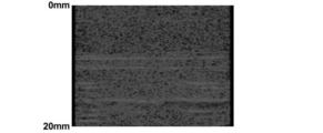
- FIG. 13 and FIG. 14 show the results of confirming the above description by actually generating and displaying a photoacoustic image (tomographic image).
- FIG. 13 is a photograph showing a photoacoustic image generated using a conventional probe having the same configuration as that of the probe 11 of this embodiment except that the slit 45 is not provided
- FIG. 14 is a photo of the probe 11 of this embodiment. It is a photograph which shows the photoacoustic image produced
- These photoacoustic images are both background images subjected to enhancement processing, and the numbers shown on the left side of each figure indicate the distance from the probe surface, that is, the depth position of the subject.
- horizontal stripe-shaped artifacts are recognized from a depth position close to 10 mm to a position of 20 mm, whereas such obvious artifacts are not recognized in the image of FIG. 14.
- each slit 45 is larger than the length of the transducer array 20. That is, when the probe 11 is viewed in plan from the surface (front surface), both end portions of the slit 45 are respectively in the direction orthogonal to the arrangement direction of the light emitting unit 40 and the transducer array 20 (left-right direction in FIG. 3).
- the transducer array 20 is located outside the both end portions. With such a configuration, the photoacoustic wave generated near the side end portion of the light emitting portion 40 is also reliably incident on the slit 45 and attenuated.
- FIG. 4 shows a side cross-sectional shape of the probe 211 of the present embodiment.
- two slits 45 similar to those in the probe 11 described above are provided.
- a portion of each slit 45 close to the housing surface 50 a is filled with a blocking member 46.
- Each blocking member 46 is arranged so that the surface thereof is flush with the housing surface 50 a and in close contact with the housing 50. By arranging such a blocking member 46, it is possible to prevent foreign matter and the like from entering the slit 45.
- the blocking member 46 is made of a material having an acoustic impedance different from that of the housing 50. Examples of such a combination of two materials include, but are not limited to, a material of the casing 50 made of ABS resin and a material of the blocking member 46 made of silicone rubber.
- the acoustic impedance of the former material is 2.3 ⁇ 10 6 Pa ⁇ s /
- the acoustic impedance of the latter material is about 1.2 ⁇ 10 6 Pa ⁇ s / m to 1.5 ⁇ 10 6 Pa ⁇ s / m.
- the blocking member 46 is preferably made of a material having a high acoustic attenuation rate.
- the photoacoustic wave is reflected by the portion of the slit 45 where the blocking member 46 does not exist in the same manner as in the probe 11 of the first embodiment. Attenuates.
- the effect of attenuating the photoacoustic wave is also obtained in the portion of the slit 45 where the blocking member 46 exists. That is, at both end portions of each blocking member 46 (the end portion on the transducer array 20 side and the end portion on the light emitting portion 40 side), there are interfaces where two materials having different acoustic impedances are in close contact with each other. ing. These two interfaces extend from the housing surface 50a toward the inside of the housing. Therefore, when a photoacoustic wave generated in the vicinity of one light emitting unit 40 propagates through the blocking member 46 and proceeds toward the transducer array 20, the photoacoustic wave is reflected at the two interfaces. Therefore, it does not reach the transducer array 20 with high intensity. The same applies to the photoacoustic wave that occurs in the vicinity of another light emitting unit 40 and travels toward the transducer array 20.
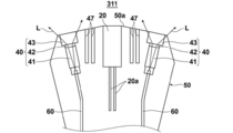
- FIG. 5 shows a side cross-sectional shape of the probe 311 of this embodiment.
- the width between the light emitting unit 40 and the transducer array 20 and the width between the other light emitting unit 40 and the transducer array 20 are slightly larger than the slit 45 in the probe 11 described above.
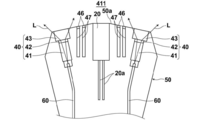
- FIG. 6 shows a side cross-sectional shape of the probe 411 of the present embodiment.
- the probe 411 is the same as that in the probe 311 of the third embodiment between one light emitting unit 40 and the transducer array 20 and between the other light emitting unit 40 and the transducer array 20.
- the two slits 47 are provided.
- the portions close to the respective housing surfaces 50a of the four slits 47 are filled with the same blocking member 46 as that in the second embodiment shown in FIG.
- Each blocking member 46 is arranged so that the surface thereof is flush with the housing surface 50 a and in close contact with the housing 50.
- the present embodiment can basically obtain the same operations and effects as those of the second embodiment.
- four interfaces of two materials having different acoustic impedances exist between one light emitting unit 40 and the transducer array 20. Therefore, when the photoacoustic wave generated in the vicinity of each light emitting portion 40 propagates through the blocking member 46 and travels toward the transducer array 20, the photoacoustic wave is transmitted four times at the interface as described above. Reflected and more attenuated. There are also four interfaces between the material of the housing 50 and air between one light emitting unit 40 and the transducer array 20.
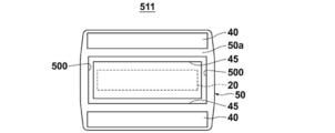
- FIG. 7 shows the front shape of the probe 511 of this embodiment.
- This probe 511 is the same as that in the probe 11 of the first embodiment between one light emitting unit 40 and the transducer array 20 and between the other light emitting unit 40 and the transducer array 20.
- the two slits 45 are provided.
- the two slits 45 are connected to each other by one slit and another slit 500 between the other ends. That is, the transducer array 20 is surrounded by the slit 45 and the slit 500 over the entire circumference.
- each light emitting portion 40 propagates outside the both end portions of the slit 45.
- the transducer array 20 is reached around the inside.
- the photoacoustic waves that wrap around as described above reach the transducer array 20. Is also prevented.
- the slit 500 may be discontinuous on the way.
- the photoacoustic image is generated and displayed using the probe 511 of the present embodiment, it is generated in the photoacoustic image as compared with the case where the photoacoustic image is generated and displayed using the probe 11 shown in FIG. Artifacts to do are reduced significantly.
- FIG. 8 shows a side cross-sectional shape of the probe 611 of the present embodiment.
- the material constituting the housing 50 is acoustic impedance between one light emitting unit 40 and the transducer array 20 and between the other light emitting unit 40 and the transducer array 20.
- a blocking member 48 made of a different material is disposed. Examples of such a combination of two materials include, but are not limited to, a material of the casing 50 made of ABS resin and a material of the blocking member 48 made of silicone rubber.
- the acoustic impedance of the former material is about 2.3 ⁇ 10 6 Pa ⁇ s / m
- the acoustic impedance of the latter material is 1.2 ⁇ 10 6 Pa ⁇ s / m to 1.5 ⁇ 10 6 Pa.
- -It is about s / m.
- the blocking member 48 is preferably made of a material having a high acoustic attenuation rate.
- the material of the blocking member 48 may be a foamed or porous plastic member.
- a combination of a plurality of members such as an upper part of the blocking member 48 such as silicone rubber and a lower part of the plastic member may be used. Since such a plastic member includes a large number of interfaces having different acoustic impedances inside, a further effect that photoacoustic waves are reflected and scattered within the member can be obtained.
- the surface of the blocking member 48 is arranged so as to be flush with the housing surface 50 a and in close contact with the housing 50.
- a blocking member 48 is provided with a slit similar to the slit 45 shown in FIG. 2 in the housing 50, and a material having an acoustic impedance different from that of the material constituting the housing 50 is applied to the slit. It can be created by filling over the depth.
- the housing 50 is made by, for example, injection molding, it can be made by embedding a material different from the housing material.
- the housing 50 after the housing 50 is created, it can be created by altering a part of the housing 50.
- the outer surface (on the light emitting unit 40 side) and the inner side (on the transducer array 20 side) of the blocking member 48 have interfaces where two materials having different acoustic impedances are in close contact with each other. These two interfaces extend from the housing surface 50a toward the inside of the housing. Therefore, as in the case where the blocking member 46 shown in FIG. 4 is provided, when a photoacoustic wave generated in the vicinity of one light emitting portion 40 attempts to travel toward the transducer array 20, the photoacoustic is obtained. Since the waves are reflected and attenuated at the two interfaces, respectively, the waves do not reach the transducer array 20 with high intensity. The same applies to the photoacoustic wave that occurs in the vicinity of another light emitting unit 40 and travels toward the transducer array 20.
- the blocking member 48 has both end portions outside the both end portions of the transducer array 20 with respect to the direction orthogonal to the arrangement direction of the light emitting portion 40 and the transducer array 20. Has been created to be located. Therefore, both ends of the interface between the blocking member 48 and the housing 50 are located outside the both ends of the transducer array 20. Therefore, the photoacoustic wave generated in the vicinity of each of both end portions of the light emitting unit 40 is reliably incident on this interface and reflected and attenuated.
- the blocking member 48 may be formed so as to surround the periphery of the transducer array 20 similarly to the slits 45 and 500 shown in FIG. In such a case, since the interface between the blocking member 48 and the casing 50 also surrounds the transducer array 20, the photoacoustic wave wraps around from the end side of the transducer array 20 and enters the transducer array 20. It is prevented from being detected. Note that the blocking member 48 newly disposed to surround the transducer array 20 (the blocking member 48 disposed at a position corresponding to the slit 500) may be discontinuous.
- FIG. 9 shows a side cross-sectional shape of the probe 711 of this embodiment.
- the probe 711 is different from the probe 611 of the sixth embodiment shown in FIG. 8 in that two blocking members 49 thinner than the blocking member 48 are provided instead of the one blocking member 48.
- These blocking members 49 are also made of a material having an acoustic impedance different from that of the material constituting the housing 50.
- the same operation and effect as those in the probe 611 of the sixth embodiment shown in FIG. 8 can be obtained.
- four interfaces of two materials having different acoustic impedances exist between one light emitting unit 40 and the transducer array 20. Therefore, when the photoacoustic wave generated in the vicinity of each light emitting portion 40 tries to travel toward the transducer array 20, the photoacoustic wave is reflected at the interface as described above four times in total and attenuated more greatly. Will come to do. Thereby, even when a photoacoustic image is generated and displayed using the probe 711 of this embodiment, occurrence of artifacts in the photoacoustic image is prevented.
- FIG. 10 shows a side cross-sectional shape of the probe 811 of this embodiment.
- the probe 811 is not provided with the blocking member 48, and instead, the housing 50 is composed of two types of materials 50 ⁇ / b> A and 50 ⁇ / b> B. It is different.
- the casing materials 50A and 50B have different acoustic impedances.
- the casing material 50A is used for a portion including the transducer array 20, and the casing material 50B is a light emitting portion on the outside of the material 50A. It is used for the part which contains 40.
- one interface between the two casing materials 50A and 50B having different acoustic impedances exists between one light emitting unit 40 and the transducer array 20. Therefore, when a photoacoustic wave generated in the vicinity of each light emitting portion 40 attempts to travel toward the transducer array 20, a part of the photoacoustic wave is reflected by the above-described interface and attenuates. . Thereby, even when a photoacoustic image is generated and displayed using the probe 811 of this embodiment, occurrence of artifacts in the photoacoustic image is prevented.
- the combination of the casing materials 50A and 50B include those in which the casing material 50A is ABS resin and the casing material 50B is acrylic resin, but the combination is not limited thereto.
- the acoustic impedance of the housing material 50A is about 2.3 ⁇ 10 6 Pa ⁇ s / m
- the acoustic impedance of the housing material 50B is about 3.2 ⁇ 10 6 Pa ⁇ s / m.
- the housing 50 is configured from the two housing materials 50A and 50B, a material having an acoustic impedance different from that of each housing material is disposed in the housing material 50A or the housing material 50B.
- the number of interfaces where two materials having different acoustic impedances are in close contact with each other can be further increased.
- the blocking member 48 as shown in FIG. 8 is disposed in the housing material 50B, three interfaces are present between the light emitting unit 40 and the transducer array 20.
- a slit may be provided at the boundary between the casing material 50A and the casing material 50B to insert another member. Moreover, when doing so, the slit may surround the transducer array 20. Furthermore, when the slit as described above is not provided, the boundary between the casing material 50A and the casing material 50B may be configured to surround the transducer array 20.
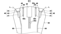
- FIG. 11 shows a side cross-sectional shape of the probe 911 of the present embodiment.
- This probe 911 is different from the probe 611 of the sixth embodiment shown in FIG. 8 in that the blocking member 46 is provided and the shape of the slit 50c of the housing 50 is different. More specifically, the blocking member 46 is fixed to the casing 50 so as to be flush with the casing surface 50a so as to cover the blocking member 48 from the probe surface side.
- the slit 50c that receives the blocking member 48 has a shape in which a plurality of irregularities that are serrated in the cross section and repeated in the slit depth direction are provided on the inner wall, that is, the wall surface on the transducer array 20 side.
- the blocking member 48 is Novec (registered trademark) 7100, which is a fluorinated solvent of 3M Company, or Fluorinert (registered trademark) FC-40, which is a fluorinated inert liquid of the same company.
- Novec 7100 is one of the hydrofluoroethers that are fluorinated liquids described above
- Fluorinert FC-40 is one of the perfluorocarbons that are also fluorinated liquids.
- the acoustic impedance is about 2.3 ⁇ 10 6 Pa ⁇ s / m as described above.
- the acoustic impedance of Novec 7100 is about 0.9 ⁇ 10 6 Pa ⁇ s / m
- the acoustic impedance of Fluorinert FC-40 is about 1.2 ⁇ 10 6 Pa ⁇ s / m. Therefore, also in the present embodiment, there are two interfaces where two materials having different acoustic impedances are in close contact with each other on the outer side (light emitting unit 40 side) and the inner side (vibrator array 20 side) of the blocking member 48. It is in a state extending from the body surface 50a toward the inside of the housing.
- the photoacoustic wave that is going to travel toward the transducer array 20 is scattered by these irregularities. Therefore, even if the photoacoustic wave reaches the transducer array 20, the photoacoustic wave is in a scattered state. From this point, the occurrence of the artifact is more reliably prevented.
- the subject M is generally a living body such as a human body. Since a living body usually contains a lot of water, the speed of sound in a living body at room temperature is about 1450 m / s to 1560 m / s in water. On the other hand, the sound speeds in the above-mentioned Novec7100 and Fluorinert FC-40 are 599.0 m / s and 636.4 m / s, respectively, which are about 40% of the sound speed in water.
- the probe 11 is configured as a hand-held type, the above-described depth of the slit 50c does not particularly lengthen the probe 11, and therefore the probe 11 has a reasonable size.
- the blocking member 48 is made of a general resin having an acoustic impedance different from that of the ABS resin mentioned above (for example, about 2.8 ⁇ 10 6 Pa ⁇ s / m).
- the speed of sound in the general resin is usually around 2000 m / s. Therefore, when the blocking member 48 is formed of such a general resin, if a photoacoustic image from the surface of the living body to a depth of 30 mm is generated as described above, a resin material thickness of about 40 mm is required. Become. The reason will be described below.
- an artifact generated from the probe housing 50 is displayed at a depth position of 30 mm or more from the living body surface in the photoacoustic wave image.
- the sound velocity V in the housing 50 is 2000 m / s as described above
- the observation time T of the photoacoustic wave generated at a depth of 30 mm from the living body surface and the equation (1) are used.
- the depth of the slit 50c needs to be about 40 mm.
- the probe 11 is configured as a hand-held type, if the depth of the slit 50c is required to be about 40 mm, the probe 11 becomes remarkably long for that reason, and it becomes very difficult to use as a hand-held type. .
- All of the probes according to the embodiments described above are formed by placing the transducer array 20 as an acoustic wave detection element in between and one light emitting section 40 on each side thereof.
- the probe is not limited to such a probe, and a probe in which a plurality of light emitting portions are disposed on at least one of both sides of one acoustic wave detecting element, or only one acoustic wave detecting element and one light emitting portion are provided.
- the present invention is also applicable to a probe having a plurality of acoustic wave detection elements.
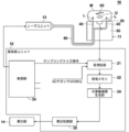
- FIG. 15 shows an example of the photoacoustic measuring apparatus 10 configured as described above.
- the photoacoustic measurement apparatus 10 shown in FIG. 15 has a configuration in which the data separation unit 23, the ultrasonic image generation unit 29, and the transmission control circuit 33 are removed as compared with the one shown in FIG.
- the photoacoustic measuring device 10 demonstrated above is comprised so that a photoacoustic image may be produced
- the probe of this invention is not restricted to that kind of photoacoustic measuring device, but detected photoacoustic
- the present invention is applicable to all photoacoustic measurement devices that perform some measurement based on waves. That is, if the probe of the present invention is applied to a photoacoustic measuring apparatus, it is widely prevented that the artifacts as described above adversely affect the measurement result.
Landscapes
- Health & Medical Sciences (AREA)
- Life Sciences & Earth Sciences (AREA)
- Physics & Mathematics (AREA)
- Engineering & Computer Science (AREA)
- General Health & Medical Sciences (AREA)
- Pathology (AREA)
- Veterinary Medicine (AREA)
- Public Health (AREA)
- Animal Behavior & Ethology (AREA)
- Surgery (AREA)
- Biophysics (AREA)
- Biomedical Technology (AREA)
- Heart & Thoracic Surgery (AREA)
- Medical Informatics (AREA)
- Molecular Biology (AREA)
- Signal Processing (AREA)
- Acoustics & Sound (AREA)
- General Physics & Mathematics (AREA)
- Chemical & Material Sciences (AREA)
- Biochemistry (AREA)
- Analytical Chemistry (AREA)
- Immunology (AREA)
- Psychiatry (AREA)
- Artificial Intelligence (AREA)
- Computer Vision & Pattern Recognition (AREA)
- Physiology (AREA)
- Radiology & Medical Imaging (AREA)
- Nuclear Medicine, Radiotherapy & Molecular Imaging (AREA)
- Optics & Photonics (AREA)
- Ultra Sonic Daignosis Equipment (AREA)
- Investigating Or Analyzing Materials By The Use Of Ultrasonic Waves (AREA)
Abstract
La présente invention a pour but d'obtenir une sonde pour une mesure photo-acoustique et une unité de sonde qui soient capables d'éviter l'apparition d'un artefact dans un dispositif de mesure photo-acoustique. Pour atteindre ce but, l'invention concerne une sonde pour une mesure photo-acoustique 11 qui comporte : des unités d'émission de lumière 40 qui émettent une lumière de mesure L vers un sujet ; un élément de détection d'onde acoustique 20 qui détecte des ondes acoustiques qui sont émises par une partie du sujet qui a reçu l'éclairage de la lumière de mesure L ; un corps de boîtier 50 qui comprend une surface 50a qui fait face au sujet pendant l'utilisation, et qui loge les unités d'émission de lumière 40 et l'élément de détection d'onde acoustique 20 à l'intérieur de celui-ci. Au moins une fente 45 est disposée entre les unités d'émission de lumière 40 et l'élément de détection d'onde acoustique 20 qui s'étend vers l'intérieur du corps de boîtier depuis la surface de corps de boîtier 50a et qui s'ouvre dans la surface de corps de boîtier 50A.
Priority Applications (2)
| Application Number | Priority Date | Filing Date | Title |
|---|---|---|---|
| EP15876976.0A EP3243443A4 (fr) | 2015-01-08 | 2015-12-04 | Sonde pour mesure photo-acoustique, unité de sonde la comprenant et dispositif de mesure photo-acoustique |
| US15/642,907 US11344204B2 (en) | 2015-01-08 | 2017-07-06 | Photoacoustic measurement probe and probe unit and photoacoustic measurement apparatus including the same |
Applications Claiming Priority (4)
| Application Number | Priority Date | Filing Date | Title |
|---|---|---|---|
| JP2015002676 | 2015-01-08 | ||
| JP2015-002676 | 2015-01-08 | ||
| JP2015184763A JP6381043B2 (ja) | 2015-01-08 | 2015-09-18 | 光音響計測用プローブ並びにそれを備えたプローブユニットおよび光音響計測装置 |
| JP2015-184763 | 2015-09-18 |
Related Child Applications (1)
| Application Number | Title | Priority Date | Filing Date |
|---|---|---|---|
| US15/642,907 Continuation US11344204B2 (en) | 2015-01-08 | 2017-07-06 | Photoacoustic measurement probe and probe unit and photoacoustic measurement apparatus including the same |
Publications (1)
| Publication Number | Publication Date |
|---|---|
| WO2016111103A1 true WO2016111103A1 (fr) | 2016-07-14 |
Family
ID=56355805
Family Applications (1)
| Application Number | Title | Priority Date | Filing Date |
|---|---|---|---|
| PCT/JP2015/084107 WO2016111103A1 (fr) | 2015-01-08 | 2015-12-04 | Sonde pour mesure photo-acoustique, unité de sonde la comprenant et dispositif de mesure photo-acoustique |
Country Status (2)
| Country | Link |
|---|---|
| US (1) | US11344204B2 (fr) |
| WO (1) | WO2016111103A1 (fr) |
Families Citing this family (1)
| Publication number | Priority date | Publication date | Assignee | Title |
|---|---|---|---|---|
| US11266315B2 (en) * | 2015-12-04 | 2022-03-08 | The Research Foundation For The State University Of New York | Devices and methods for photoacoustic tomography |
Citations (2)
| Publication number | Priority date | Publication date | Assignee | Title |
|---|---|---|---|---|
| JP2013176542A (ja) * | 2012-02-03 | 2013-09-09 | Fujifilm Corp | プローブ |
| JP2013255707A (ja) * | 2012-06-13 | 2013-12-26 | Canon Inc | 被検体情報取得装置、および、光音響プローブ |
Family Cites Families (4)
| Publication number | Priority date | Publication date | Assignee | Title |
|---|---|---|---|---|
| US5433207A (en) * | 1993-11-15 | 1995-07-18 | Pretlow, Iii; Robert A. | Method and apparatus to characterize ultrasonically reflective contrast agents |
| JP2012166009A (ja) | 2011-01-28 | 2012-09-06 | Fujifilm Corp | 超音波プローブ |
| JP5697615B2 (ja) | 2011-02-07 | 2015-04-08 | 富士フイルム株式会社 | 超音波プローブ |
| KR102149322B1 (ko) | 2013-05-20 | 2020-08-28 | 삼성메디슨 주식회사 | 광음향 프로브 어셈블리 및 이를 포함하는 광음향 영상 장치 |
-
2015
- 2015-12-04 WO PCT/JP2015/084107 patent/WO2016111103A1/fr active Application Filing
-
2017
- 2017-07-06 US US15/642,907 patent/US11344204B2/en active Active
Patent Citations (2)
| Publication number | Priority date | Publication date | Assignee | Title |
|---|---|---|---|---|
| JP2013176542A (ja) * | 2012-02-03 | 2013-09-09 | Fujifilm Corp | プローブ |
| JP2013255707A (ja) * | 2012-06-13 | 2013-12-26 | Canon Inc | 被検体情報取得装置、および、光音響プローブ |
Non-Patent Citations (1)
| Title |
|---|
| See also references of EP3243443A4 * |
Also Published As
| Publication number | Publication date |
|---|---|
| US11344204B2 (en) | 2022-05-31 |
| US20170296063A1 (en) | 2017-10-19 |
Similar Documents
| Publication | Publication Date | Title |
|---|---|---|
| JP5907918B2 (ja) | 光音響計測装置および光音響計測方法並びにプローブの接触判断方法 | |
| JP5349839B2 (ja) | 生体情報イメージング装置 | |
| JP4469903B2 (ja) | 生体情報イメージング装置 | |
| JP5855994B2 (ja) | 音響波検出用のプローブおよびそれを備えた光音響計測装置 | |
| JP2010075681A (ja) | 光音響装置および光音響波を受信するための探触子 | |
| JP2010088627A5 (fr) | ||
| JP5702313B2 (ja) | 光音響分析用プローブユニットおよび光音響分析装置 | |
| JP2012170762A (ja) | 光音響分析用プローブユニットおよび光音響分析装置 | |
| JP6172912B2 (ja) | 被検体情報取得装置および光音響プローブ | |
| JP6475369B2 (ja) | 音響波画像生成装置および音響波画像生成方法 | |
| US11399719B2 (en) | Probe for photoacoustic measurement and photoacoustic measurement apparatus including same | |
| WO2016111103A1 (fr) | Sonde pour mesure photo-acoustique, unité de sonde la comprenant et dispositif de mesure photo-acoustique | |
| JP6408163B2 (ja) | 光音響計測用プローブ並びにそれを備えたプローブユニットおよび光音響計測装置 | |
| JP6381043B2 (ja) | 光音響計測用プローブ並びにそれを備えたプローブユニットおよび光音響計測装置 | |
| JP2013188489A (ja) | 被検体情報処理装置およびその作動方法 | |
| WO2014192488A1 (fr) | Sonde de mesure photoacoustique et unité de sonde et dispositif de mesure photoacoustique qui en sont munis | |
| JP2014184025A (ja) | 光音響計測装置、プローブおよび音響整合部材並びに光音響計測方法およびプローブの接触判断方法 | |
| JP2012090862A (ja) | 光音響検査用探触子および光音響検査装置 | |
| JP6262679B2 (ja) | 光音響計測装置 | |
| JP6463414B2 (ja) | 音響波プローブおよび音響波装置 | |
| JP2016187484A (ja) | 注液針および光音響計測装置 | |
| JP6005211B2 (ja) | 画像情報取得装置及び画像情報取得方法 | |
| JP2014069032A (ja) | 被検体情報取得装置 |
Legal Events
| Date | Code | Title | Description |
|---|---|---|---|
| 121 | Ep: the epo has been informed by wipo that ep was designated in this application |
Ref document number: 15876976 Country of ref document: EP Kind code of ref document: A1 |
|
| REEP | Request for entry into the european phase |
Ref document number: 2015876976 Country of ref document: EP |
|
| NENP | Non-entry into the national phase |
Ref country code: DE |