WO2016110942A1 - 濾過材、濾過材の製造方法、濾過装置、濾過装置の運転方法及び濾過処理システム - Google Patents
濾過材、濾過材の製造方法、濾過装置、濾過装置の運転方法及び濾過処理システム Download PDFInfo
- Publication number
- WO2016110942A1 WO2016110942A1 PCT/JP2015/050127 JP2015050127W WO2016110942A1 WO 2016110942 A1 WO2016110942 A1 WO 2016110942A1 JP 2015050127 W JP2015050127 W JP 2015050127W WO 2016110942 A1 WO2016110942 A1 WO 2016110942A1
- Authority
- WO
- WIPO (PCT)
- Prior art keywords
- filter medium
- water
- filtration
- treated
- turbidity
- Prior art date
- Legal status (The legal status is an assumption and is not a legal conclusion. Google has not performed a legal analysis and makes no representation as to the accuracy of the status listed.)
- Ceased
Links
Images







Classifications
-
- C—CHEMISTRY; METALLURGY
- C01—INORGANIC CHEMISTRY
- C01B—NON-METALLIC ELEMENTS; COMPOUNDS THEREOF; METALLOIDS OR COMPOUNDS THEREOF NOT COVERED BY SUBCLASS C01C
- C01B32/00—Carbon; Compounds thereof
- C01B32/30—Active carbon
-
- B—PERFORMING OPERATIONS; TRANSPORTING
- B01—PHYSICAL OR CHEMICAL PROCESSES OR APPARATUS IN GENERAL
- B01D—SEPARATION
- B01D24/00—Filters comprising loose filtering material, i.e. filtering material without any binder between the individual particles or fibres thereof
- B01D24/46—Regenerating the filtering material in the filter
- B01D24/4631—Counter-current flushing, e.g. by air
-
- B—PERFORMING OPERATIONS; TRANSPORTING
- B01—PHYSICAL OR CHEMICAL PROCESSES OR APPARATUS IN GENERAL
- B01D—SEPARATION
- B01D37/00—Processes of filtration
- B01D37/03—Processes of filtration using flocculating agents
-
- B—PERFORMING OPERATIONS; TRANSPORTING
- B01—PHYSICAL OR CHEMICAL PROCESSES OR APPARATUS IN GENERAL
- B01D—SEPARATION
- B01D61/00—Processes of separation using semi-permeable membranes, e.g. dialysis, osmosis or ultrafiltration; Apparatus, accessories or auxiliary operations specially adapted therefor
- B01D61/02—Reverse osmosis; Hyperfiltration ; Nanofiltration
- B01D61/025—Reverse osmosis; Hyperfiltration
-
- B—PERFORMING OPERATIONS; TRANSPORTING
- B01—PHYSICAL OR CHEMICAL PROCESSES OR APPARATUS IN GENERAL
- B01D—SEPARATION
- B01D61/00—Processes of separation using semi-permeable membranes, e.g. dialysis, osmosis or ultrafiltration; Apparatus, accessories or auxiliary operations specially adapted therefor
- B01D61/02—Reverse osmosis; Hyperfiltration ; Nanofiltration
- B01D61/04—Feed pretreatment
-
- B—PERFORMING OPERATIONS; TRANSPORTING
- B01—PHYSICAL OR CHEMICAL PROCESSES OR APPARATUS IN GENERAL
- B01D—SEPARATION
- B01D61/00—Processes of separation using semi-permeable membranes, e.g. dialysis, osmosis or ultrafiltration; Apparatus, accessories or auxiliary operations specially adapted therefor
- B01D61/58—Multistep processes
-
- B—PERFORMING OPERATIONS; TRANSPORTING
- B01—PHYSICAL OR CHEMICAL PROCESSES OR APPARATUS IN GENERAL
- B01D—SEPARATION
- B01D69/00—Semi-permeable membranes for separation processes or apparatus characterised by their form, structure or properties; Manufacturing processes specially adapted therefor
- B01D69/02—Semi-permeable membranes for separation processes or apparatus characterised by their form, structure or properties; Manufacturing processes specially adapted therefor characterised by their properties
-
- B—PERFORMING OPERATIONS; TRANSPORTING
- B01—PHYSICAL OR CHEMICAL PROCESSES OR APPARATUS IN GENERAL
- B01D—SEPARATION
- B01D71/00—Semi-permeable membranes for separation processes or apparatus characterised by the material; Manufacturing processes specially adapted therefor
- B01D71/02—Inorganic material
- B01D71/021—Carbon
-
- B—PERFORMING OPERATIONS; TRANSPORTING
- B01—PHYSICAL OR CHEMICAL PROCESSES OR APPARATUS IN GENERAL
- B01J—CHEMICAL OR PHYSICAL PROCESSES, e.g. CATALYSIS OR COLLOID CHEMISTRY; THEIR RELEVANT APPARATUS
- B01J20/00—Solid sorbent compositions or filter aid compositions; Sorbents for chromatography; Processes for preparing, regenerating or reactivating thereof
- B01J20/02—Solid sorbent compositions or filter aid compositions; Sorbents for chromatography; Processes for preparing, regenerating or reactivating thereof comprising inorganic material
- B01J20/20—Solid sorbent compositions or filter aid compositions; Sorbents for chromatography; Processes for preparing, regenerating or reactivating thereof comprising inorganic material comprising free carbon; comprising carbon obtained by carbonising processes
-
- B—PERFORMING OPERATIONS; TRANSPORTING
- B01—PHYSICAL OR CHEMICAL PROCESSES OR APPARATUS IN GENERAL
- B01J—CHEMICAL OR PHYSICAL PROCESSES, e.g. CATALYSIS OR COLLOID CHEMISTRY; THEIR RELEVANT APPARATUS
- B01J20/00—Solid sorbent compositions or filter aid compositions; Sorbents for chromatography; Processes for preparing, regenerating or reactivating thereof
- B01J20/28—Solid sorbent compositions or filter aid compositions; Sorbents for chromatography; Processes for preparing, regenerating or reactivating thereof characterised by their form or physical properties
- B01J20/28054—Solid sorbent compositions or filter aid compositions; Sorbents for chromatography; Processes for preparing, regenerating or reactivating thereof characterised by their form or physical properties characterised by their surface properties or porosity
- B01J20/28057—Surface area, e.g. B.E.T specific surface area
- B01J20/28066—Surface area, e.g. B.E.T specific surface area being more than 1000 m2/g
-
- B—PERFORMING OPERATIONS; TRANSPORTING
- B01—PHYSICAL OR CHEMICAL PROCESSES OR APPARATUS IN GENERAL
- B01J—CHEMICAL OR PHYSICAL PROCESSES, e.g. CATALYSIS OR COLLOID CHEMISTRY; THEIR RELEVANT APPARATUS
- B01J20/00—Solid sorbent compositions or filter aid compositions; Sorbents for chromatography; Processes for preparing, regenerating or reactivating thereof
- B01J20/28—Solid sorbent compositions or filter aid compositions; Sorbents for chromatography; Processes for preparing, regenerating or reactivating thereof characterised by their form or physical properties
- B01J20/28054—Solid sorbent compositions or filter aid compositions; Sorbents for chromatography; Processes for preparing, regenerating or reactivating thereof characterised by their form or physical properties characterised by their surface properties or porosity
- B01J20/28069—Pore volume, e.g. total pore volume, mesopore volume, micropore volume
-
- B—PERFORMING OPERATIONS; TRANSPORTING
- B01—PHYSICAL OR CHEMICAL PROCESSES OR APPARATUS IN GENERAL
- B01J—CHEMICAL OR PHYSICAL PROCESSES, e.g. CATALYSIS OR COLLOID CHEMISTRY; THEIR RELEVANT APPARATUS
- B01J20/00—Solid sorbent compositions or filter aid compositions; Sorbents for chromatography; Processes for preparing, regenerating or reactivating thereof
- B01J20/28—Solid sorbent compositions or filter aid compositions; Sorbents for chromatography; Processes for preparing, regenerating or reactivating thereof characterised by their form or physical properties
- B01J20/28054—Solid sorbent compositions or filter aid compositions; Sorbents for chromatography; Processes for preparing, regenerating or reactivating thereof characterised by their form or physical properties characterised by their surface properties or porosity
- B01J20/28078—Pore diameter
- B01J20/28083—Pore diameter being in the range 2-50 nm, i.e. mesopores
-
- B—PERFORMING OPERATIONS; TRANSPORTING
- B01—PHYSICAL OR CHEMICAL PROCESSES OR APPARATUS IN GENERAL
- B01J—CHEMICAL OR PHYSICAL PROCESSES, e.g. CATALYSIS OR COLLOID CHEMISTRY; THEIR RELEVANT APPARATUS
- B01J20/00—Solid sorbent compositions or filter aid compositions; Sorbents for chromatography; Processes for preparing, regenerating or reactivating thereof
- B01J20/28—Solid sorbent compositions or filter aid compositions; Sorbents for chromatography; Processes for preparing, regenerating or reactivating thereof characterised by their form or physical properties
- B01J20/28054—Solid sorbent compositions or filter aid compositions; Sorbents for chromatography; Processes for preparing, regenerating or reactivating thereof characterised by their form or physical properties characterised by their surface properties or porosity
- B01J20/28088—Pore-size distribution
- B01J20/28092—Bimodal, polymodal, different types of pores or different pore size distributions in different parts of the sorbent
-
- B—PERFORMING OPERATIONS; TRANSPORTING
- B01—PHYSICAL OR CHEMICAL PROCESSES OR APPARATUS IN GENERAL
- B01J—CHEMICAL OR PHYSICAL PROCESSES, e.g. CATALYSIS OR COLLOID CHEMISTRY; THEIR RELEVANT APPARATUS
- B01J20/00—Solid sorbent compositions or filter aid compositions; Sorbents for chromatography; Processes for preparing, regenerating or reactivating thereof
- B01J20/30—Processes for preparing, regenerating, or reactivating
-
- B—PERFORMING OPERATIONS; TRANSPORTING
- B01—PHYSICAL OR CHEMICAL PROCESSES OR APPARATUS IN GENERAL
- B01J—CHEMICAL OR PHYSICAL PROCESSES, e.g. CATALYSIS OR COLLOID CHEMISTRY; THEIR RELEVANT APPARATUS
- B01J20/00—Solid sorbent compositions or filter aid compositions; Sorbents for chromatography; Processes for preparing, regenerating or reactivating thereof
- B01J20/30—Processes for preparing, regenerating, or reactivating
- B01J20/3085—Chemical treatments not covered by groups B01J20/3007 - B01J20/3078
-
- C—CHEMISTRY; METALLURGY
- C01—INORGANIC CHEMISTRY
- C01B—NON-METALLIC ELEMENTS; COMPOUNDS THEREOF; METALLOIDS OR COMPOUNDS THEREOF NOT COVERED BY SUBCLASS C01C
- C01B32/00—Carbon; Compounds thereof
- C01B32/30—Active carbon
- C01B32/312—Preparation
-
- C—CHEMISTRY; METALLURGY
- C01—INORGANIC CHEMISTRY
- C01B—NON-METALLIC ELEMENTS; COMPOUNDS THEREOF; METALLOIDS OR COMPOUNDS THEREOF NOT COVERED BY SUBCLASS C01C
- C01B32/00—Carbon; Compounds thereof
- C01B32/30—Active carbon
- C01B32/312—Preparation
- C01B32/336—Preparation characterised by gaseous activating agents
-
- C—CHEMISTRY; METALLURGY
- C02—TREATMENT OF WATER, WASTE WATER, SEWAGE, OR SLUDGE
- C02F—TREATMENT OF WATER, WASTE WATER, SEWAGE, OR SLUDGE
- C02F1/00—Treatment of water, waste water, or sewage
- C02F1/008—Control or steering systems not provided for elsewhere in subclass C02F
-
- C—CHEMISTRY; METALLURGY
- C02—TREATMENT OF WATER, WASTE WATER, SEWAGE, OR SLUDGE
- C02F—TREATMENT OF WATER, WASTE WATER, SEWAGE, OR SLUDGE
- C02F1/00—Treatment of water, waste water, or sewage
- C02F1/28—Treatment of water, waste water, or sewage by sorption
- C02F1/283—Treatment of water, waste water, or sewage by sorption using coal, charred products, or inorganic mixtures containing them
-
- C—CHEMISTRY; METALLURGY
- C02—TREATMENT OF WATER, WASTE WATER, SEWAGE, OR SLUDGE
- C02F—TREATMENT OF WATER, WASTE WATER, SEWAGE, OR SLUDGE
- C02F1/00—Treatment of water, waste water, or sewage
- C02F1/44—Treatment of water, waste water, or sewage by dialysis, osmosis or reverse osmosis
- C02F1/441—Treatment of water, waste water, or sewage by dialysis, osmosis or reverse osmosis by reverse osmosis
-
- C—CHEMISTRY; METALLURGY
- C02—TREATMENT OF WATER, WASTE WATER, SEWAGE, OR SLUDGE
- C02F—TREATMENT OF WATER, WASTE WATER, SEWAGE, OR SLUDGE
- C02F1/00—Treatment of water, waste water, or sewage
- C02F1/52—Treatment of water, waste water, or sewage by flocculation or precipitation of suspended impurities
-
- B—PERFORMING OPERATIONS; TRANSPORTING
- B01—PHYSICAL OR CHEMICAL PROCESSES OR APPARATUS IN GENERAL
- B01D—SEPARATION
- B01D2101/00—Types of filters having loose filtering material
- B01D2101/02—Carbon filters
-
- B—PERFORMING OPERATIONS; TRANSPORTING
- B01—PHYSICAL OR CHEMICAL PROCESSES OR APPARATUS IN GENERAL
- B01D—SEPARATION
- B01D2101/00—Types of filters having loose filtering material
- B01D2101/04—Sand or gravel filters
-
- B—PERFORMING OPERATIONS; TRANSPORTING
- B01—PHYSICAL OR CHEMICAL PROCESSES OR APPARATUS IN GENERAL
- B01D—SEPARATION
- B01D2311/00—Details relating to membrane separation process operations and control
- B01D2311/26—Further operations combined with membrane separation processes
- B01D2311/2642—Aggregation, sedimentation, flocculation, precipitation or coagulation
-
- B—PERFORMING OPERATIONS; TRANSPORTING
- B01—PHYSICAL OR CHEMICAL PROCESSES OR APPARATUS IN GENERAL
- B01D—SEPARATION
- B01D2321/00—Details relating to membrane cleaning, regeneration, sterilization or to the prevention of fouling
- B01D2321/04—Backflushing
-
- B—PERFORMING OPERATIONS; TRANSPORTING
- B01—PHYSICAL OR CHEMICAL PROCESSES OR APPARATUS IN GENERAL
- B01D—SEPARATION
- B01D61/00—Processes of separation using semi-permeable membranes, e.g. dialysis, osmosis or ultrafiltration; Apparatus, accessories or auxiliary operations specially adapted therefor
- B01D61/02—Reverse osmosis; Hyperfiltration ; Nanofiltration
- B01D61/06—Energy recovery
-
- B—PERFORMING OPERATIONS; TRANSPORTING
- B01—PHYSICAL OR CHEMICAL PROCESSES OR APPARATUS IN GENERAL
- B01D—SEPARATION
- B01D61/00—Processes of separation using semi-permeable membranes, e.g. dialysis, osmosis or ultrafiltration; Apparatus, accessories or auxiliary operations specially adapted therefor
- B01D61/14—Ultrafiltration; Microfiltration
-
- B—PERFORMING OPERATIONS; TRANSPORTING
- B01—PHYSICAL OR CHEMICAL PROCESSES OR APPARATUS IN GENERAL
- B01D—SEPARATION
- B01D65/00—Accessories or auxiliary operations, in general, for separation processes or apparatus using semi-permeable membranes
- B01D65/02—Membrane cleaning or sterilisation ; Membrane regeneration
-
- B—PERFORMING OPERATIONS; TRANSPORTING
- B01—PHYSICAL OR CHEMICAL PROCESSES OR APPARATUS IN GENERAL
- B01D—SEPARATION
- B01D67/00—Processes specially adapted for manufacturing semi-permeable membranes for separation processes or apparatus
- B01D67/0081—After-treatment of organic or inorganic membranes
- B01D67/0083—Thermal after-treatment
-
- B—PERFORMING OPERATIONS; TRANSPORTING
- B01—PHYSICAL OR CHEMICAL PROCESSES OR APPARATUS IN GENERAL
- B01D—SEPARATION
- B01D67/00—Processes specially adapted for manufacturing semi-permeable membranes for separation processes or apparatus
- B01D67/0081—After-treatment of organic or inorganic membranes
- B01D67/0088—Physical treatment with compounds, e.g. swelling, coating or impregnation
-
- C—CHEMISTRY; METALLURGY
- C01—INORGANIC CHEMISTRY
- C01P—INDEXING SCHEME RELATING TO STRUCTURAL AND PHYSICAL ASPECTS OF SOLID INORGANIC COMPOUNDS
- C01P2006/00—Physical properties of inorganic compounds
- C01P2006/14—Pore volume
-
- C—CHEMISTRY; METALLURGY
- C01—INORGANIC CHEMISTRY
- C01P—INDEXING SCHEME RELATING TO STRUCTURAL AND PHYSICAL ASPECTS OF SOLID INORGANIC COMPOUNDS
- C01P2006/00—Physical properties of inorganic compounds
- C01P2006/16—Pore diameter
-
- C—CHEMISTRY; METALLURGY
- C02—TREATMENT OF WATER, WASTE WATER, SEWAGE, OR SLUDGE
- C02F—TREATMENT OF WATER, WASTE WATER, SEWAGE, OR SLUDGE
- C02F1/00—Treatment of water, waste water, or sewage
- C02F1/52—Treatment of water, waste water, or sewage by flocculation or precipitation of suspended impurities
- C02F1/5236—Treatment of water, waste water, or sewage by flocculation or precipitation of suspended impurities using inorganic agents
- C02F1/5245—Treatment of water, waste water, or sewage by flocculation or precipitation of suspended impurities using inorganic agents using basic salts, e.g. of aluminium and iron
-
- C—CHEMISTRY; METALLURGY
- C02—TREATMENT OF WATER, WASTE WATER, SEWAGE, OR SLUDGE
- C02F—TREATMENT OF WATER, WASTE WATER, SEWAGE, OR SLUDGE
- C02F1/00—Treatment of water, waste water, or sewage
- C02F1/66—Treatment of water, waste water, or sewage by neutralisation; pH adjustment
-
- C—CHEMISTRY; METALLURGY
- C02—TREATMENT OF WATER, WASTE WATER, SEWAGE, OR SLUDGE
- C02F—TREATMENT OF WATER, WASTE WATER, SEWAGE, OR SLUDGE
- C02F2103/00—Nature of the water, waste water, sewage or sludge to be treated
- C02F2103/007—Contaminated open waterways, rivers, lakes or ponds
-
- C—CHEMISTRY; METALLURGY
- C02—TREATMENT OF WATER, WASTE WATER, SEWAGE, OR SLUDGE
- C02F—TREATMENT OF WATER, WASTE WATER, SEWAGE, OR SLUDGE
- C02F2103/00—Nature of the water, waste water, sewage or sludge to be treated
- C02F2103/08—Seawater, e.g. for desalination
-
- C—CHEMISTRY; METALLURGY
- C02—TREATMENT OF WATER, WASTE WATER, SEWAGE, OR SLUDGE
- C02F—TREATMENT OF WATER, WASTE WATER, SEWAGE, OR SLUDGE
- C02F2209/00—Controlling or monitoring parameters in water treatment
- C02F2209/11—Turbidity
-
- C—CHEMISTRY; METALLURGY
- C02—TREATMENT OF WATER, WASTE WATER, SEWAGE, OR SLUDGE
- C02F—TREATMENT OF WATER, WASTE WATER, SEWAGE, OR SLUDGE
- C02F2303/00—Specific treatment goals
- C02F2303/10—Energy recovery
-
- C—CHEMISTRY; METALLURGY
- C02—TREATMENT OF WATER, WASTE WATER, SEWAGE, OR SLUDGE
- C02F—TREATMENT OF WATER, WASTE WATER, SEWAGE, OR SLUDGE
- C02F2303/00—Specific treatment goals
- C02F2303/16—Regeneration of sorbents, filters
-
- Y—GENERAL TAGGING OF NEW TECHNOLOGICAL DEVELOPMENTS; GENERAL TAGGING OF CROSS-SECTIONAL TECHNOLOGIES SPANNING OVER SEVERAL SECTIONS OF THE IPC; TECHNICAL SUBJECTS COVERED BY FORMER USPC CROSS-REFERENCE ART COLLECTIONS [XRACs] AND DIGESTS
- Y02—TECHNOLOGIES OR APPLICATIONS FOR MITIGATION OR ADAPTATION AGAINST CLIMATE CHANGE
- Y02W—CLIMATE CHANGE MITIGATION TECHNOLOGIES RELATED TO WASTEWATER TREATMENT OR WASTE MANAGEMENT
- Y02W10/00—Technologies for wastewater treatment
- Y02W10/30—Wastewater or sewage treatment systems using renewable energies
Definitions
- the present invention relates to a filtering material, a filtering material manufacturing method, a filtering device, a filtering device operating method, and a filtering processing system, and more specifically, a filtering material capable of efficiently removing turbidity in water to be treated, a filtering material manufacturing method,
- the present invention relates to a filtration device, an operation method of the filtration device, and a filtration processing system.
- a water purifier filler using fibrous activated carbon has been proposed (see, for example, Patent Document 1).
- a fibrous activated carbon having a pore radius of 0.9 nm or more and 1.6 nm or less occupied by pores within a predetermined range and a specific surface area of 1300 m 2 / g or more is used. By using it, it is possible to efficiently remove trihalomethane present in tap water at a very low concentration of about several ppb.
- a dual media filter that reduces the turbidity concentration by filtering seawater supplied to the reverse osmosis membrane filtration device in order to prevent fouling of the reverse osmosis membrane
- a filtration device such as (DMF: Dual Media Filter)
- DMF Dual Media Filter
- a general activated carbon used as a filtering material in a conventional filtration device has a specific surface area of 1000 m 2 / g or more, and has many fine pores with a diameter of several nanometers. There is no significant difference between the pores and the molecular diameter of turbidity such as organic matter contained in seawater. For this reason, with conventional filter media, it is difficult to quickly remove the turbidity adsorbed on the activated carbon even if backwashing is performed, and the filtration device may not always be operated efficiently.
- the present invention has been made in view of such circumstances, and a filter medium, a filter medium manufacturing method, a filter apparatus, and a filter that can quickly regenerate the adsorptive power by backwashing and realize efficient operation of the filter apparatus. It is an object of the present invention to provide an apparatus operating method and a filtration processing system.
- the filter medium of the present invention is characterized in that the cumulative pore volume of pores having a pore radius of 2 nm or less is 25% or less with respect to the cumulative pore volume of pores having a pore radius of 50 nm or less.
- micropores having a pore radius of 0.8 nm to 2 nm and sub-micropores having a pore radius of 0.8 nm or less which are difficult for the suspended matter adsorbed at the time of backwashing to be detached from the filter medium, are reduced. It becomes possible to quickly desorb turbidity from the filter medium during backwashing. As a result, it is possible to realize a filter medium that can regenerate the adsorption force more rapidly by backwashing and realize more efficient operation of the filtration device.
- the filter medium of the present invention preferably contains a carbon-based material.
- the carbon-based material preferably contains activated carbon.
- the method for producing a filter medium according to the present invention is a method for producing the above-described filter medium, characterized in that a carbonaceous material is activated by steam.
- the method for producing a filter medium according to the present invention is a method for producing the above-mentioned filter medium, wherein the carbon-based material is activated with carbon dioxide gas.
- micropores having a pore radius of 0.8 nm or more and 2 nm or less in the carbon-based material are appropriately destroyed to accumulate pores having a pore radius of 50 nm or less.
- the cumulative pore volume of pores having a pore radius of 2 nm or less can be 25% or less with respect to the pore volume.
- the activation treatment is performed with steam under a condition that the surface temperature of the carbonaceous material is 750 ° C. or higher.
- the method for producing a filter medium can appropriately destroy micropores having a pore radius of 2 nm or less in the carbon-based material, so that the cumulative pore volume of pores having a pore radius of 50 nm or less of the filter medium is reduced. It becomes easy to make the cumulative pore volume of pores having a pore radius of 2 nm or less 25% or less.
- the method for producing a filter medium of the present invention it is preferable to perform the activation treatment with carbon dioxide gas under the condition that the surface temperature of the carbon-based material is 850 ° C. or higher.
- the method for producing a filter medium can appropriately destroy micropores having a pore radius of 2 nm or less in the carbon-based material, so that the cumulative pore volume of pores having a pore radius of 50 nm or less of the filter medium is reduced. It becomes easy to make the cumulative pore volume of pores having a pore radius of 2 nm or less 25% or less.
- the method for producing a filter medium of the present invention it is preferable to perform the activation treatment until the mass reduction of the carbon-based material reaches 50% or more.
- the pore radius with respect to the cumulative pore volume of pores having a pore radius of 50 nm or less of the filter medium It becomes easy to make the cumulative pore volume of pores of 2 nm or less 25% or less.
- the filtration device of the present invention is characterized by comprising the filtration material obtained by the filtration material or the method for producing the filtration material.
- the filtration apparatus since the cumulative pore volume of pores having a pore radius of 2 nm or less is provided with a filter medium having a cumulative pore volume of 25% or less with respect to the cumulative pore volume of pores having a pore radius of 50 nm or less, The turbidity contained in the water can be efficiently removed, and the turbidity held on the filter medium can be efficiently desorbed from the filter medium during backwashing. Therefore, the filtration device can realize a filtration device that can quickly regenerate the adsorption force by backwashing and realize efficient operation.
- the operation method of the filtration device of the present invention is the operation method of the filtration device, wherein a filtration step of filtering the water to be treated with the filter material to reduce turbidity in the water to be treated, and filtration with the filter material
- a filtration step of filtering the water to be treated with the filter material to reduce turbidity in the water to be treated and filtration with the filter material
- the amount of turbidity in the treated water is 1/3 or more of the total amount of adsorption of the filter medium, it includes a cleaning step of cleaning the filter medium by reverse cleaning.
- this filtration device it is possible to perform back washing under conditions that have a sufficient margin for the adsorption capacity of the filtration material, and therefore it is difficult to remove turbidity in the water to be treated. It becomes possible to prevent the adsorption
- the driving method can be realized.
- the operation method of the filtration device of the present invention is the operation method of the filtration device, wherein the first turbidity concentration in the treated water and the second turbidity in the filtered water in which the treated water is filtered by the filtering material. Calculate the difference value between the turbidity concentration measuring step for measuring the concentration and the measured first time integral value of the first turbidity concentration and the measured second time integral value of the second turbidity concentration. And a filtering medium cleaning step of performing reverse cleaning of the filtering medium when the difference value is equal to or less than a predetermined value.
- the filter medium is back-washed. Therefore, it becomes possible to wash
- the driving method can be realized.
- the filtration treatment system of the present invention comprises a treated water filtration unit provided with the above filtration device for filtering treated water supplied from a treated water line to obtain filtered water, and filtering the filtered water through a separation membrane. And a salinity concentration unit for obtaining permeated water and concentrated water.
- micropores having a pore radius of 0.8 nm or more and 2 nm or less and sub-micropores having a pore radius of 0.8 nm or less which are difficult for turbidity adsorbed during backwashing to be detached from the filter medium, were reduced. Since the filtration device is provided, it becomes possible to quickly desorb turbidity from the filter medium during backwashing. Thereby, the adsorption
- a filter medium a filter medium manufacturing method, a filter apparatus, a filter apparatus operation method, and a filtration processing system that can quickly regenerate the adsorptive power by backwashing and realize an efficient operation of the filter apparatus.
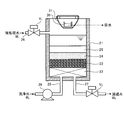
- FIG. 1 is a schematic view of a water treatment apparatus according to an embodiment of the present invention.
- FIG. 2 is a schematic cross-sectional view showing an example of a multilayer filtration device according to an embodiment of the present invention.
- FIG. 3 is a schematic view of a filter medium using general activated carbon.
- FIG. 4 is a schematic view of a filter medium according to an embodiment of the present invention.
- FIG. 5A is a diagram showing the relationship between the filtration time of a filter medium using general activated carbon and the suspended water turbidity concentration.
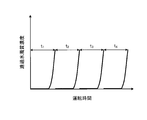
- FIG. 5B is a diagram showing a relationship between the filtration time of the filter medium and the suspended water turbidity concentration according to one embodiment of the present invention.
- FIG. 5A is a diagram showing the relationship between the filtration time of a filter medium using general activated carbon and the suspended water turbidity concentration.
- FIG. 5B is a diagram showing a relationship between the filtration time of the filter medium and the suspended water turbidity concentration according to one
- FIG. 6 is a diagram showing the relationship between the cumulative pore volume and the pore radius of the filter medium according to one embodiment of the present invention.
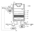
- FIG. 7 is a schematic cross-sectional view showing another example of the multilayer filtration device according to one embodiment of the present invention.
- FIG. 8 is a flowchart of the operation method of the filtration device according to the embodiment of the present invention.
- FIG. 9 is a schematic diagram of a filtration system according to an embodiment of the present invention.
- FIG. 1 is a schematic view of a water treatment apparatus according to an embodiment of the present invention.
- the water treatment device 1 according to the present embodiment is configured to filter water W 2 obtained by filtering the water to be treated W 1 using a water to be treated filtering unit 11 as a multi-layer filtration device. It is a water treatment device that obtains permeated water W 3 and concentrated water W 4 by filtering with the reverse osmosis membrane 12 a of the reverse osmosis membrane filtration unit 12.
- the water to be treated W 1 is not particularly limited, for example, sea water, river water, lake water, ground water, urban sewage, brackish, industrial water, and industrial waste water, as well as aggregation of these water, precipitation, filtration, adsorption Water subjected to treatment such as biological treatment can be used.
- the water treatment apparatus 1 includes a treated water filtering unit 11 to which treated water W 1 is supplied from the treated water line L 1 and a filtered water line L 2 subsequent to the treated water filtering unit 11. It includes a reverse osmosis membrane filtration unit 12 provided, the energy recovery unit 13 disposed downstream of the concentrated water line L 3 of the reverse osmosis membrane filtration unit 12, to.
- the treated water W 1 is supplied from the treated water line L 1 to the treated water filtering unit 11 by the liquid feed pump 14.
- the treated water filtering unit 11 filters the treated water W 1 to obtain filtered water W 2 from which turbidity in the treated water W 1 has been removed.
- the to-be-processed water filtration part 11 it is relative with respect to the 1st filtration layer 24 (not shown in FIG. 1, refer FIG. 2) containing the filtration material which concerns on this Embodiment, and the filtration material which concerns on this Embodiment, for example.
- a dual media filter (DMF: Dual Media Filter) in which a second filtration layer 25 (not shown in FIG. 1, refer to FIG. 2) containing cinnabar sand having a small particle diameter is laminated can be used.
- pH of the filtered water W 2 is predetermined value (e.g., pH 7.2 or less) so as to be adjusted as necessary with an acid such as H 2 SO 4, HCl.
- an acid such as H 2 SO 4, HCl.
- the reverse osmosis membrane filtration unit 12 is supplied with filtered water W 2 pressurized from the filtered water line L 2 by the high-pressure pump 15.
- the reverse osmosis membrane filtration unit 12 permeates the filtered water W 2 supplied from the treated water filtration unit 11 to make the permeated water W 3, and the concentrated water W 4 in which the salt content in the filtered water W 2 is concentrated.
- the reverse osmosis membrane 12a is provided.
- the reverse osmosis membrane filtration unit 12 discharges the concentrated water W 4 from the concentrated water line L 3 and discharges the permeated water W 3 from the permeated water line L 4 .
- a filter member such as a micro cartridge filter may be further provided between the treated water filtering unit 11 and the reverse osmosis membrane filtering unit 12.
- the energy recovery unit 13 recovers the energy of the high-pressure concentrated water W 4 pressurized by the high-pressure pump 15.
- the recovered energy energy recovery device 13 is used, for example, energy pressure converting energy and filtered water W 2 drives the high-pressure pump 15 to a high pressure. Thereby, the water treatment apparatus 1 can improve the energy efficiency of the water treatment apparatus 1 whole.
- the energy recovery unit 13 for example, a PeltonWheel type energy recovery device, a Turbocharger type energy recovery device, a PX (Pressure Exchanger) type energy recovery device, a DWEER (DualWork Energy Exchanger) type energy recovery device, or the like can be used.
- FIG. 2 is a schematic cross-sectional view of the treated water filtration unit 11 according to the present embodiment.
- this to-be-processed water filtration part 11 is a gravity filtration apparatus.
- This to-be-processed water filtration part 11 has the rectangular parallelepiped filtration tank 21, for example.
- a perforated block 22 as a filter bed is provided at the lower portion of the filtration tank 21.
- an underlayer 23 is provided by gravel laid in layers.
- a first filtration layer 24 is provided on the base layer 23 by sand laid in layers.
- the 2nd filtration layer 25 is provided with the filter material spread
- the 2nd filtration tank 25 is comprised including the filter material which concerns on this Embodiment.
- This filter medium has a relatively lighter specific gravity than the sand constituting the first filter layer 24, and the particle diameter of the filter medium is relatively larger than that of sand.
- a treated water supply pipe 26 is provided above the filtration tank 21 above the second filtration layer 25. From this treated water supply pipe 26, seawater to be treated water W 1 is supplied into the filtration tank 21. Note that a flocculant such as ferric chloride is added to the seawater.
- the treated water supply pipe 26 is provided with a flow rate adjusting valve V 1 that opens and closes the treated water supply pipe 26 to adjust the flow rate of the treated water W 1 .
- a filtered water discharge pipe 27 is provided below the perforated block 22 at the lower portion of the filtration tank 21.
- the filtered water outlet pipe 27 is provided with a flow rate adjusting valve V 2 that can open and close the filtered water outlet pipe 27 and adjust the flow rate of the filtered water W 2 .
- a washing water supply pipe 28 is provided below the perforated block 22 at the lower part of the filtration tank 21.
- the washing water supply pipe 28 is provided with a liquid feeding pump 29 for feeding the washing water W 5 into the filtration tank 21.
- a drainage basin 30 that is substantially U-shaped in cross-sectional view and extends in a substantially horizontal direction is provided above the second filtration layer 25.
- the drainage basin 30 is supported by the filtration tank 21 via a beam member (not shown). Both ends of the drainage basin 30 are connected to drainage ports (not shown) formed in the wall of the filtration tank 21. Further, the drainage basin 30 has a position of the upper surface in the vertical direction below the upper end of the filtration tank 21.
- a filter material outflow prevention net 31 for preventing the filter material from flowing out is provided. This filter material outflow prevention net 31 is supported by the filter tank 21 by a support member (not shown).
- This filtered water W 2 is discharged out of the filtration tank 21 through the filtered water outlet pipe 27.
- the first filter layer 24 and the second filtration layer cleaning water W 5 is supplied into the filter tank 21 from the washing water supply pipe 28 provided in the lower by feeding pump 29 of the filtration tank 21 25 is backwashed.
- the cleaning water W 5 sequentially passes perforated block 22, the underlayer 23, a first filter layer 24 and the second filtration layer 25 as upflow.
- the turbidity adsorbed on the first filtration layer 24 and the second filtration layer 25 is detached from the first filtration layer 24 and the second filtration layer 25 and removed as waste water by the washing water W 5 .
- the 2nd filtration layer 25 is reproduced
- Drainage containing turbidity is drained through a drainage basin 30 installed at the top of the filtration tank 21.
- the first filtration layer 24 and the second filter layer 25 is suspended solid concentration in the filtered water W 2 is predetermined concentration or more (e.g., total organic carbon concentration (TOC: Total Organic Carbon) in 2 mg / kg) reached In this case, it is determined that the first filtration layer 24 and the second filtration layer 25 have reached the turbid adsorption equilibrium, and are back-washed.
- TOC Total Organic Carbon
- the filter medium according to the present embodiment constitutes the second filtration layer 25 described above, and has a pore radius of 2 nm or less with respect to the cumulative pore volume of pores with a pore radius of 50 nm or less.
- the cumulative pore volume is 25% or less.
- the pore radius and the pore volume are values measured by a nitrogen adsorption method based on JIS Z 8831-2: 2010 and JIS Z 8831-2: 2010.
- FIG. 3 is a schematic diagram of a filter medium using general activated carbon
- FIG. 4 is a schematic diagram of the filter medium according to the present embodiment.
- a filter medium 100 using general activated carbon has a macropore 101 having a pore radius of 50 nm or more on the surface.
- a plurality of mesopores 102 having a pore radius of 2 nm to 50 nm are formed.
- a large number of micropores 103 having a pore radius of 0.8 nm to 2 nm are formed in the plurality of mesopores 102.
- micropores 103 In the large number of micropores 103, submicropores (not shown) having a pore radius of 0.8 nm or less are formed.
- the filter material 100, the total pore volume, micropore 103 accounts for 75% or less than 25%
- the size of the specific surface area is 1000 m 2 / g or more, the water to be treated W in 1
- the adsorbing capacity of turbidity is excellent.
- the molecular radius of a polymer such as polysaccharide that is turbid in the water to be treated W 1 has a radius equivalent to the inner diameter of the micropore 103, and the turbidity adsorbed in the back of the micropore 103 is In some cases, even when washing water is passed through the backwashing of the filtration device, the state of being adsorbed on the filter medium 100 is maintained and the filter medium 100 is not easily detached. Furthermore, since the polymer adsorbed in the pores may be gradually eluted over a long period of time, the adsorption performance of the filter medium is lowered.
- the filter medium 200 in the filter medium 200 according to the present embodiment, a part of the micropores 103 of the filter medium 200 is destroyed by an activation process or the like, and the accumulated fine pores having a pore radius of 50 nm or less.
- the cumulative pore volume of pores having a pore radius of 2 nm or less is 25% or less with respect to the pore volume.
- FIG. 5A is a diagram showing the relationship between the filtration time of a filter medium using general activated carbon and the turbidity concentration of filtered water W 2
- FIG. 5B shows the filtration time of the filter medium according to the present embodiment. It is a diagram showing the relationship between turbidity concentration of the filtered water W 2.
- the cumulative pore volume of the pores exceeds 25%. For this reason, when a general filter medium is used, the operation time t1 from the start of the operation until the first back filtration of the filter medium 100 becomes longer, while the filtration from the second time to the fourth time is performed. The operation time t2 to t4 until the material 100 is back cleaned is significantly shortened.
- turbidity is adsorbed by a large number of micropores 103 in the filter medium 100 until the first back washing after the start of operation, so a relatively long operation time t1 is required until the first back washing. It is thought that it was secured.
- the turbidity once adsorbed to the micropores 103 is only desorbed from the filter medium 100 to some extent even by backwashing, and many micropores 103 are blocked by the turbidity, so the second to fourth backwashing is performed. This is probably because the operation time t2 to t4 has become shorter.
- the operation time t1 from the start of operation until the first backwashing of the filter medium 200 is generally performed using activated carbon.
- the operation time t2 to t4 from the second time to the fourth time until the backwashing of the filter medium 200 is substantially constant, similar to the operation time t1, and the first backwash to the fourth backwash.
- the total operation time t1 to t4 is longer than that in the case of the filter medium 100.
- the ratio of the micropores 103 in which the adsorbed turbidity is difficult to desorb is moderately reduced to the cumulative pore volume of pores having a pore radius of 50 nm or less. Since the cumulative pore volume of pores having a pore radius of 2 nm or less is 25% or less, the suspended matter adsorbed on the filter medium 200 by backwashing can be efficiently desorbed and the filter medium 200 can be efficiently regenerated. It is thought that it was because of.
- the cumulative pore volume of pores having a pore radius of 2 nm or less is 25% of the cumulative pore volume of pores having a pore radius of 50 nm or less. Therefore, the pore radius of the pores of the filter medium 200 is appropriately increased with respect to the molecular diameter of turbid substances such as organic substances contained in the water to be treated W 1 . Adsorption of turbidity can be appropriately prevented, and the turbidity retained on the filter medium 200 can be efficiently detached from the filter medium 200 during backwashing. Accordingly, the filter medium 200 can quickly desorb the suspended matter adsorbed at the time of backwashing without impairing the adsorption efficiency of the suspended matter in the water W 1 to be treated. This makes it possible to perform efficient operation of the filtration device.
- the specific surface area of the filter medium 200 As the specific surface area of the filter medium 200 according to the present embodiment, 100 m 2 / g or more is preferable because the adsorption capacity of turbid matter contained in the water to be treated W 1 is improved. Thereby, compared with the case where the specific surface area of the filter medium 200 is less than 100 m 2 / g, the time until the filter medium 200 breaks through becomes longer, so that the operation time until backwashing can be increased. The operating efficiency of the filtration device is improved.
- this filter medium 200 from the viewpoint of further improving the above-mentioned turbidity adsorption capacity, 150 m 2 / g or more is preferable, 200 m 2 / g or more is more preferable, and turbidity is more improved during backwashing. From the viewpoint of more efficient desorption, 800 m 2 / g or less is preferable, 500 m 2 / g or less is more preferable, and 400 m 2 / g or less is more preferable.
- the specific surface area of the filter medium 200 is preferably 100 m 2 / g or more and 800 m 2 / g or less, more preferably 150 m 2 / g or more and 500 m 2 / g or less, and 200 m 2 / g or more and 400 m 2 / g or less. Is more preferable.
- FIG. 6 is a diagram showing the relationship between the cumulative pore volume and pore radius of the filter medium 200 according to the present embodiment.
- the horizontal axis represents the pore radius (nm) of the filter medium 200
- the vertical axis represents the cumulative pore volume (%) of the filter medium 200.
- the specific surface area is set to 100 m 2 / g or more and 800 m 2 / g or less by appropriately removing the micropores 103 having a pore radius of 2 nm or less by activation treatment or the like.
- the cumulative pore volume of pores having a pore radius of 2 nm or less is lower than that of general activated carbon, and the pore radius can be 25% or less with respect to the cumulative pore volume of pores having a radius of 50 nm or less. .
- the micropores 103 having a pore radius of 0.8 nm to 2 nm and sub-micropores having a pore radius of 0.8 nm or less that are difficult to be detached from the filter medium during backwashing are reduced. It is possible to quickly desorb the quality. As a result, it is possible to realize a filter medium that can regenerate the adsorption force more quickly by backwashing and realize more efficient operation of the filtration device.
- the cumulative pore volume of pores having a radius of 2 nm or less is smaller than the cumulative pore volume of pores having a pore radius of 50 nm or less. 25% or less is preferable, 10% or less is more preferable, and 1% or less is still more preferable.
- the cumulative pore volume will be described.
- the saturated vapor pressure decreases depending on the curvature of the filter medium surface due to the effect of surface tension, so that the adsorption capacity increases by increasing the specific surface area and increasing the curved surface.
- the saturated vapor pressure P 0 r in the pore having the pore radius r is represented by the following Kelvin equation (1).
- the adsorption capacity increases, and as p 0 decreases, the adsorption capacity increases.
- Formula (1) (In formula (1), p 0 represents the saturated vapor pressure of the liquid plane, V m represents the surface molar volume of the liquid, ⁇ represents the surface tension of the liquid, and R represents the gas constant. T represents the absolute temperature, and ⁇ represents the contact angle between the liquid and the pore wall.)
- the cumulative pore volume is determined from the pore radius distribution.
- the pore radius distribution can be obtained by comparing adsorption isotherms such as t-plot method and ⁇ s -plot method according to JIS Z 8831-3: 2010. In these methods, the pore radius distribution is determined by measuring a nitrogen isothermal adsorption line representing the relationship between the adsorption capacity and the pressure and comparing it with a standard sample. Since the adsorption capacity increases due to the presence of the pores, the pore radius distribution is determined by obtaining the pore volume from the increase in the adsorption capacity corresponding to the pore radius.
- the filter medium 200 various filter materials can be used as long as the effects of the present invention are achieved.
- the filter medium 200 include various ceramics such as alumina, coal, charcoal, coal coke, petroleum coke, pitch coke, activated carbon using these, and carbon black as a thermosetting resin such as pitch / tar binder / phenol.
- Various carbon-based materials such as granular activated carbon granulated with activated carbon, activated alumina, activated clay, silica gel, and zeolite can be used.
- the filter medium 200 is preferably made of at least one of a carbon-based material and activated carbon, and more preferably made of activated carbon.
- the above-described various carbon-based materials are activated with water vapor and / or carbon dioxide gas, thereby accumulating fine pores having a pore radius of 50 nm or less of the carbon-based material.
- the filter medium 200 is manufactured by setting the cumulative pore volume of pores having a pore radius of 2 nm or less to 25% or less with respect to the pore volume.
- the specific surface area of the carbon-based material can be reduced by appropriately destroying the micropores 103 having a pore radius of 2 nm or less in the carbon-based material by activation treatment with at least one of water vapor and carbon dioxide gas.
- the cumulative pore volume of pores having a pore radius of 50 nm or less With respect to the cumulative pore volume of pores having a pore radius of 50 nm or less, the cumulative pore volume of pores having a pore radius of 2 nm or less can be reduced to 25% or less.
- it is possible to efficiently adsorb contaminants of the water to be treated W in 1, can be produced filtration material 200 that can be quickly desorbed contaminants from the filtration media during backwashing.
- the surface temperature of the carbon-based material is 750 ° C. or more and 850 ° C. or less, and the condition is 12 hours or more and 72 hours or less longer than the activation treatment of a general activated carbon. preferable.
- the activation treatment is performed with carbon dioxide gas, the condition that the surface temperature of the carbon-based material is 850 ° C. or more and 950 ° C. or less and is 12 hours or more and 72 hours or less longer than the activation treatment of general activated carbon is preferable.
- the micropores having a pore radius of 2 nm or less in the carbon-based material are appropriately destroyed, and the cumulative pore volume of pores having a pore radius of 50 nm or less is reduced.
- the conditions for the activation treatment it is preferable to carry out the activation treatment under the above-described temperature and time conditions until the mass loss due to gasification of the carbon-based material is 50% or more.
- the destruction of the micropores 103 having a pore radius of 2 nm or less in the carbon-based material is in an appropriate range, so that the cumulative pore volume of pores having a pore radius of 50 nm or less is smaller than the pore radius of 2 nm or less. It is possible to easily obtain the filter medium 200 having a cumulative pore volume of 25% or less.
- the mass decrement in the activation treatment is performed using the filter medium 200 in which the cumulative pore volume of pores having a pore radius of 2 nm or less is 25% or less with respect to the cumulative pore volume of pores having a pore radius of 50 nm or less. From the viewpoint of easier production, 75% or more is more preferable, and 80% or more is even more preferable.
- the cumulative pore volume of pores having a pore radius of 2 nm or less is smaller than the cumulative pore volume of pores having a pore radius of 50 nm or less. Since 25% or less, it is possible to with the contaminants contained in the water to be treated W during 1 can efficiently remove the contaminants retained efficiently filtering material during backwashing detached from the filtering material . Therefore, it is possible to realize the filter medium 200 that can quickly regenerate the adsorptive power by backwashing and realize efficient operation of the filtration device. By using the filter medium 200, the filter apparatus can be efficiently operated only by applying the filter medium 200 without significantly changing the structure of the filter apparatus main body.
- the filter medium 200 according to the present embodiment is applied to the treated water filtering unit 11 .
- the present invention is not limited to the treated water filtering unit 11 and is various. Applicable to filtration devices.
- the operation method of the filtration device according to the present embodiment includes a filtration step of filtering the water to be treated with the filter material to reduce turbidity in the water to be treated, and a filtration with the filter material with respect to the total adsorption amount of the filter material. And a cleaning step of back-washing the filter medium when the amount of suspended matter in the treated water becomes one third or more. That is, the operation method of the filtration device according to the present embodiment is that the total amount of adsorption of the filter medium with respect to the turbidity concentration in the water to be treated passes through the filter medium during the operation period of the backwash interval of the filtration device. It is intended to be at least three times the integrated amount. In the operation method of the filtration device according to the present embodiment, it is not always necessary to use the filtration material 200 according to the above embodiment as the filtration material, and various types of filtration materials can be used.
- this filtration apparatus it becomes possible to perform back washing under conditions that have a sufficient margin for the adsorption capacity of the filter medium, so that excessive adsorption of turbidity in the pores of the filter medium Can be prevented.
- the filtration device is operated in a range that has a sufficient margin for the adsorption capacity of the filter medium. Permeation of the filtration device can be prevented.
- there is a margin in the adsorption capacity of the filter medium thus preventing permeation of the turbid filter in the water to be treated.
- the suspended matter adsorbed on the filter medium can be quickly desorbed from the filter medium at the time of backwashing, so that the adsorption power can be quickly regenerated by backwashing and an efficient operation can be realized.
- the driving method can be realized.
- the total adsorption amount of the filter medium with respect to the turbidity concentration in the water to be treated is the operation of the backwash interval of the filtration device. It is preferable that the accumulated amount of turbidity passing through the filter medium during the period is 5 times or more, and more preferably 10 times or more.
- the type and amount of filter medium are determined so as to satisfy the following relational expression.
- the amount of filter media adsorbed per unit mass at the turbidity concentration in treated water (mg / kg) x amount of filter media used (kg) ⁇ turbidity concentration of treated water (mg / kg)-turbidity of filtered water Quality concentration (mg / kg) ⁇ ⁇ operation time between backwashing of filtration device (h) ⁇ flow rate of water to be treated permeating filter material (m 3 / h) ⁇ 1000 ⁇ 3 (or 5, or 10)
- FIG. 7 is a diagram illustrating another example of the filtration device according to the present embodiment.
- the filtration device 210 is a treated water turbidimeter (treated water turbidity concentration measurement) provided in the treated water supply pipe 26.
- a device 211
- a filtered water turbidity meter (filtered water contaminants concentration measuring device) 212 provided in the filtered water water discharge pipe 27, turbidity of the water to be treated W in 1 measured by treated water turbidity meter 211 It calculates the turbidity mass has been in filtered water W 2 determined by the mass and filtered water turbidity meter 212, and a control unit 213 for controlling the operation of the filtration device 210 according to the result.
- Treated water turbidity meter 211 is provided on the upstream side with respect to the filtering material 200 in the channel of the for-treatment water W 1, measuring the concentration of suspended substances in the water to be treated W during 1 before being filtered by the filtering material 200 To do.
- Filtered water turbidity meter 212 is provided on the downstream side with respect to the filtering material 200 in the channel of the for-treatment water W 1, measuring the concentration of the filtered water W 2 is the water to be treated W 1 after being filtered by the filtering material To do.
- the treated water turbidimeter 211 and the filtered water turbidimeter 212 are not particularly limited as long as the concentration of the treated water W 1 or the filtered water W 2 can be measured.
- the control unit 213 is realized using, for example, a general-purpose or dedicated computer such as a CPU (Central Processing Unit), a ROM (Read Only Memory), a RAM (Random Access Memory), and a program operating on the computer. Controller 213 calculates a time integral value of the turbid medium concentration of the water to be treated W in 1 measured by treated water turbidity meter 211 (cumulative value per predetermined time). Further, the control unit 213 calculates a time integral value (cumulative value per predetermined time) of the turbidity concentration in the filtered water W 2 measured by the filtered water turbidimeter 212 per predetermined time.
- a general-purpose or dedicated computer such as a CPU (Central Processing Unit), a ROM (Read Only Memory), a RAM (Random Access Memory), and a program operating on the computer. Controller 213 calculates a time integral value of the turbid medium concentration of the water to be treated W in 1 measured by treated water turbidity meter 211 (cumulative value per
- Control unit 213, a difference value between the time integration value per predetermined time of the suspended solid concentration of the filtered water W 2 and the calculated time integral value per predetermined time of the suspended solid concentration of the water to be treated W in 1 calculated It is determined whether or not the calculated difference value is equal to or less than a predetermined threshold value. Furthermore, the control part 213 continues normal operation of the filtration apparatus 210, when the calculated difference value is below a predetermined threshold value.
- the control unit 213, after backwash of the filter 210, the suspended solid concentration in the filtered water W 2 and the calculated time integral value per predetermined time of the suspended solid concentration of the water to be treated W in 1 calculated predetermined After erasing the time integral value per time, the time integral value per unit time (integrated value) of the turbidity concentration in the treated water W 1 measured by the treated water turbidimeter 211 and the filtered water turbidity again.
- a time integrated value (integrated value) per predetermined time of the turbidity concentration in the filtrate W 2 measured by the dynamometer 212 is calculated.
- FIG. 8 is a flowchart of the operation method of the filtration device 210 according to the present embodiment.
- the method of operating a filtration apparatus 210 according to the present embodiment filtered water W 2 of the first suspended solid concentration and the water to be treated W 1 of the water to be treated W during 1 is filtered by the filtering material and turbidity concentration measurement step of measuring a second contaminants concentration in each first first hour integral value of the first turbidity concentration of the water to be treated W in 1 measured with (accumulated value) in the filtered water W 2 And a filter medium cleaning step of performing reverse cleaning of the filter medium based on a difference value from the second time integral value (cumulative value) of the two turbidity concentrations.
- the suspended solid concentration measurement step the water to be treated turbidimeter 211 measures the first contaminants concentration of the water to be treated W of 1 (step ST111). Further, the suspended solid concentration measuring step, filtrate turbidity meter 212 measures the second contaminants concentration in filtered water W 2 (step ST 112).
- the control unit 213, After starting the operation of the filter 210, the turbidity mass evaluation step, the control unit 213, first hour per predetermined time of the first turbidity concentration of the water to be treated W in 1 measured by treated water turbidity meter 211 An integral value is calculated (step ST121). Next, the control unit 213 calculates the second time integral value per predetermined time of the second contaminants concentration of filtrate turbidity meter 212 filtered water W 2 as measured by (step ST122).
- step ST123 A difference value from the second time integration value is calculated (step ST123), and it is determined whether or not the calculated difference value is equal to or less than a predetermined threshold value (step ST124).
- step ST124 Yes
- the control unit 213 continues normal operation of the filtering device 210 (step ST125).
- the second integrated value of the second turbidity concentration per predetermined time is deleted (step ST127).
- control unit 213 measures the first time integral value per predetermined time of the first turbidity concentration in the treated water W 1 measured by the treated water turbidimeter 211 and the filtered water turbidimeter 212 again. has been to calculate a second time integration value per predetermined time of the second turbidity concentration in filtered water W 2 (step ST111, ST112, ST121, ST122) .
- the first turbidity concentration measured by the to-be-treated turbidimeter 211 provided on the upstream side of the filter medium and the downstream side of the filter medium are provided.
- the type and amount of filter medium are determined so that the second turbidity concentration measured by the filtered water turbidimeter 212 satisfies the following relational expression.
- the first turbidity concentration first measured by the to-be-treated water turbidimeter 211 provided on the upstream side of the filter medium.
- the turbid mass adsorbed by the filter medium based on the difference between the time integral value and the second time integral value of the second turbidity concentration measured by the filtered water turbidimeter 212 provided downstream of the filter medium. Since it becomes possible to grasp correctly, the operation time of the filtration apparatus 210 until backwashing can be set sufficiently and sufficiently.
- the operation method of the filtration device 210 can prevent the performance of the filtration device 210 from being deteriorated due to poor cleaning of the suspended matter adsorbed on the filtration material at the time of backwashing that occurs when the operation time of the filtration device 210 is too long. It becomes.
- the operation method of the filtration device 210 can prevent a reduction in the operation rate of the filtration device 210 due to an increase in the number of backwashing that occurs when the operation time of the filtration device 210 is too short.
- the treated water turbidimeter 211 and the filtered water turbidimeter 212 are used, but an organic substance concentration meter such as a TO ° C. (total organic carbon) meter is used instead of the turbidimeter. It is also possible. In the case of using an organic substance concentration meter, it is possible to operate the filtration device 210 as described above with the turbidity concentration as the organic substance concentration.
- FIG. 9 is a schematic diagram of a filtration processing system 300 according to the present embodiment.
- the filtration treatment system 300 includes a filtration device 301 to which the water line L 10 to be treated is connected, and a salt concentration unit 302 provided at the subsequent stage of the filtration device 301.
- a filtered water line L 11 is provided between the filtering device 301 and the salt concentration unit 302.
- Treated water line L 10 supplies the water to be treated W 1, which is a raw water such as seawater filtration device 301.
- the filtration device 301 filters the treated water W 1 supplied from the treated water line L 10 to obtain filtered water W 2 .
- the filtration device 301 supplies the filtered water W 2 salinity concentration unit 302 via the filtrate line L 11.
- the salt concentration unit 302 transmits the filtered water W 2 through the separation membrane 302a to obtain the permeated water W 3 from which the salt content in the filtered water W 2 has been removed, and the concentrated water W in which the salt content in the filtered water W 2 is concentrated. Get 4 .
- the salt concentration unit 302 supplies the permeated water W 3 to various devices (not shown) in the subsequent stage through the permeate water line L 12 and discharges the concentrated water W 4 through the concentrate water discharge line L 13. .
- the separation membrane 302a is not particularly limited as long as permeate W 3 and concentrate W 4 is obtained from the filtered water W 2.
- the filtration device 301 includes a first filtration layer 301b and a second filtration layer 301c stacked in the filtration device main body 301a.
- the 1st filtration layer 301b is provided in the top part 301d side of the filtration apparatus main body 301a, and is comprised including the filter material 200 mentioned above.
- the 2nd filtration layer 301c is provided in the bottom part 301e side of the filter apparatus main body 301a, and is comprised including granular filter media, such as silica sand.
- filtration system 300 includes a quality evaluation unit 303 for evaluating the quality of filtered water W 2 through the filtrate line L 11, the treated water line L via a coagulant supply line L 21 a coagulant supplying unit 304 supplies a flocculant 304a to 10, control for controlling the amount of flocculant that is supplied from the coagulant supplying unit 304 on the basis of the evaluation results of the quality of filtered water W 2 of water quality evaluation device 303 Unit 305.
- Water evaluation unit 303 monitors and measures the contaminants concentration of organic matter in the water to be treated W during 1.
- Control unit 305 determines suspended solid concentration of the water to be treated W in 1 measured by the quality evaluation unit 303 to or greater than a predetermined threshold value. Then, the control unit 305, when the suspended solid concentration of the water to be treated W during 1 is above a predetermined threshold value, coagulant supply unit driving a drug supply pump 306 provided in the coagulant supply line L 21 304 supplies the flocculant 304a to be treated water line L 10 from. Further, when the turbidity concentration in the treated water W 1 is less than a predetermined threshold, the control unit 305 stops the chemical supply pump 306 and moves to the treated water line L 10 from the flocculant supply unit 304. The supply of the flocculant 304a is stopped.
- the filter device 301 having a reduced sub-micropore with a radius of 0.8 nm or less is provided, it is possible to quickly desorb turbidity from the filter medium 200 during backwashing. Thereby, the adsorption
Landscapes
- Chemical & Material Sciences (AREA)
- Organic Chemistry (AREA)
- Chemical Kinetics & Catalysis (AREA)
- Engineering & Computer Science (AREA)
- Water Supply & Treatment (AREA)
- Analytical Chemistry (AREA)
- Inorganic Chemistry (AREA)
- Life Sciences & Earth Sciences (AREA)
- Hydrology & Water Resources (AREA)
- Environmental & Geological Engineering (AREA)
- Nanotechnology (AREA)
- Water Treatment By Sorption (AREA)
Abstract
逆洗浄により吸着力を速やかに再生でき、濾過装置の効率良い運転を実現できる濾過材、濾過材の製造方法、濾過装置、濾過装置の運転方法及び濾過処理システムを提供すること。本発明の濾過材は、細孔半径50nm以下の細孔の累積細孔容積に対して、細孔半径2nm以下の細孔の累積細孔容積が25%以下の炭素系材料からなることを特徴とする。
Description
本発明は、濾過材、濾過材の製造方法、濾過装置、濾過装置の運転方法及び濾過処理システムに関し、詳しくは、被処理水中の濁質を効率良く除去できる濾過材、濾過材の製造方法、濾過装置、濾過装置の運転方法及び濾過処理システムに関する。
従来、繊維状活性炭を用いた浄水器用充填材が提案されている(例えば、特許文献1参照)。この浄水器用充填材においては、細孔半径が0.9nm以上1.6nm以下の細孔の占める累積細孔容積を所定範囲にすると共に、比表面積を1300m2/g以上とした繊維状活性炭を用いることにより、水道水中に数ppb程度と極めて低濃度で存在するトリハロメタンを効率良く除去することを可能としている。
ところで、逆浸透膜濾過装置によって海水を淡水化する淡水化装置においては、逆浸透膜の汚損を防ぐために、逆浸透膜濾過装置に供給する海水を濾過して濁質濃度を低減するデュアルメディアフィルタ(DMF:Dual Media Filter)などの濾過装置(前処理装置)が用いられている。このような濾過装置においては、海水の濾過によって活性炭などの濾過材に目詰まりが生じて圧損が上昇するので、所定期間運転後に定期的に逆洗浄を行って濾過材の汚れを除去する必要がある。
しかしながら、従来の濾過装置で濾過材として用いられている一般的な活性炭は、比表面積が1000m2/g以上であり、また、直径が数nm程度の微小な細孔が多いので、活性炭の細孔と海水に含まれる有機物などの濁質の分子径との間に大差がない。このため、従来の濾過材では、逆洗浄を行っても活性炭に吸着された濁質を速やかに除去することは困難であり、濾過装置を必ずしも効率良く運転できていない場合があった。
本発明は、このような実情に鑑みてなされたものであり、逆洗浄により吸着力を速やかに再生でき、濾過装置の効率良い運転を実現できる濾過材、濾過材の製造方法、濾過装置、濾過装置の運転方法及び濾過処理システムを提供することを目的とする。
本発明の濾過材は、細孔半径50nm以下の細孔の累積細孔容積に対して、細孔半径2nm以下の細孔の累積細孔容積が25%以下であることを特徴とする。
この構成によれば、逆洗浄時に吸着した濁質が濾過材から脱離しにくい細孔半径が0.8nm以上2nm以下のミクロポア及び細孔半径が0.8nm以下のサブミクロポアが低減されるので、逆洗浄時に濾過材から濁質を速やかに脱離させることが可能となる。これにより、逆洗浄により吸着力をより速やかに再生でき、濾過装置のより効率良い運転を実現できる濾過材を実現できる。
本発明の濾過材においては、炭素系材料を含むことが好ましい。この構成により、濾過材は、一般に濾過装置の砂濾過層に用いられている濾過砂より比重が軽くなるので、砂濾過層上に濾過層を設けることが容易になる。また、濾過材は、有機物との親和性が向上するので、被処理水中の有機物による濁質を効率良く除去することが可能となる。
本発明の濾過材においては、前記炭素系材料が活性炭を含むことが好ましい。この構成により、濾過材は、一般に濾過装置の砂濾過層に用いられている濾過砂より比重が軽くなるので、砂濾過層上に濾過層を設けることがより容易になる。また、濾過材は、有機物との親和性がより向上するので、被処理水中の有機物による濁質を効率良く除去することが可能となる。
本発明の濾過材の製造方法は、上記濾過材の製造方法であって、炭素系材料を水蒸気によって賦活処理することを特徴とする。
また、本発明の濾過材の製造方法は、上記濾過材の製造方法であって、炭素系材料を炭酸ガスによって賦活処理することを特徴とする。
これらの方法によれば、水蒸気又は炭酸ガスによる賦活処理により、炭素系材料中の細孔半径が0.8nm以上2nm以下のミクロポアを適度に破壊して、細孔半径50nm以下の細孔の累積細孔容積に対して、細孔半径2nm以下の細孔の累積細孔容積を25%以下とすることができる。これにより、濾過材の製造方法は、被処理水中の濁質を効率良く吸着できると共に、逆洗浄時に濾過材から濁質を速やかに脱離させることが可能な濾過材を実現できる。
本発明の濾過材の製造方法においては、前記炭素系材料の表面温度が750℃以上となる条件下、水蒸気によって前記賦活処理を行うことが好ましい。この方法により、濾過材の製造方法は、炭素系材料中の細孔半径が2nm以下のミクロポアを適度に破壊できるので、濾過材の細孔半径50nm以下の細孔の累積細孔容積に対して、細孔半径2nm以下の細孔の累積細孔容積を25%以下にすることが容易になる。
本発明の濾過材の製造方法においては、前記炭素系材料の表面温度が850℃以上となる条件下、炭酸ガスによって前記賦活処理を行うことが好ましい。この方法により、濾過材の製造方法は、炭素系材料中の細孔半径が2nm以下のミクロポアを適度に破壊できるので、濾過材の細孔半径50nm以下の細孔の累積細孔容積に対して、細孔半径2nm以下の細孔の累積細孔容積を25%以下にすることが容易になる。
本発明の濾過材の製造方法においては、前記炭素系材料の質量減分が50%以上となるまで前記賦活処理を行うことが好ましい。この方法により、炭素系材料中の細孔半径が2nm以下のミクロポアの破壊が適度な範囲となるので、濾過材の細孔半径50nm以下の細孔の累積細孔容積に対して、細孔半径2nm以下の細孔の累積細孔容積を25%以下にすることが容易になる。
本発明の濾過装置は、上記濾過材又は上記濾過材の製造方法によって得られた濾過材を備えたことを特徴とする。
この濾過装置によれば、細孔半径50nm以下の細孔の累積細孔容積に対して、細孔半径2nm以下の細孔の累積細孔容積が25%以下の濾過材を備えるので、被処理水中に含まれる濁質を効率良く除去できると共に、逆洗浄時に効率良く濾過材に保持された濁質を濾過材から脱離させることが可能となる。したがって、濾過装置は、逆洗浄により吸着力を速やかに再生でき、効率良い運転を実現できる濾過装置を実現できる。
本発明の濾過装置の運転方法は、上記濾過装置の運転方法であって、前記濾過材によって被処理水を濾過して前記被処理水中の濁質を低減する濾過工程と、前記濾過材によって濾過した前記被処理水中の濁質の量が前記濾過材の全吸着量に対して3分の1以上になった際に、前記濾過材を逆洗浄により洗浄する洗浄工程を含むことを特徴とする。
この濾過装置の運転方法によれば、濾過材の吸着容量に対して十分な余裕がある条件で逆洗浄を行うことが可能となるので、被処理水中の濁質の脱離が困難な濾過材中の細孔半径が2nm以下のミクロポアへの吸着を防ぐことが可能となる。これにより、逆洗浄時に速やかに濾過材に吸着された濁質を濾過材から脱離させることが可能となるので、逆洗浄により吸着力を速やかに再生でき、効率良い運転を実現できる濾過装置の運転方法を実現できる。
本発明の濾過装置の運転方法は、上記濾過装置の運転方法であって、前記被処理水中の第1濁質濃度及び前記被処理水が前記濾過材によって濾過された濾過水中の第2濁質濃度をそれぞれ測定する濁質濃度測定工程と、測定した前記第1濁質濃度の第1時間積分値と測定した前記第2濁質濃度の第2時間積分値との差分値を算出し、算出した差分値が所定値以下のときに前記濾過材の逆洗浄を実施する濾過材洗浄工程と、を含むことを特徴とする。
この濾過装置の運転方法によれば、濾過材の性能が低下して被処理水の第1濁質濃度に対して濾過水の第2濁質濃度が所定値以上になると濾過材が逆洗浄されるので、濾過水の第2濁質濃度の変化に応じて適切に濾過材を洗浄することが可能となる。これにより、逆洗浄時に速やかに濾過材に吸着された濁質を濾過材から脱離させることが可能となるので、逆洗浄により吸着力を速やかに再生でき、効率良い運転を実現できる濾過装置の運転方法を実現できる。
本発明の濾過処理システムは、被処理水ラインから供給される被処理水を濾過して濾過水とする上記濾過装置を備えた被処理水濾過部と、前記濾過水を分離膜により濾過して透過水及び濃縮水を得る塩分濃縮部とを備えたことを特徴とする。
この濾過処理システムによれば、逆洗浄時に吸着した濁質が濾過材から脱離しにくい細孔半径が0.8nm以上2nm以下のミクロポア及び細孔半径が0.8nm以下のサブミクロポアが低減された濾過装置を備えるので、逆洗浄時に濾過材から濁質を速やかに脱離させることが可能となる。これにより、逆洗浄により濾過装置の濾過材の吸着力をより速やかに再生でき、濾過処理システムのより効率良い運転を実現できる。
本発明によれば、逆洗浄により吸着力を速やかに再生でき、濾過装置の効率良い運転を実現できる濾過材、濾過材の製造方法、濾過装置、濾過装置の運転方法及び濾過処理システムを実現できる。
以下、本発明の実施の形態について、添付図面を参照して詳細に説明する。なお、以下の各実施の形態に限定されるものではなく、適宜変更して実施可能である。また、以下の各実施の形態は適宜組み合わせて実施可能である。
まず、本発明の一実施の形態に係る濾過装置を備えた水処理装置の概略について簡単に説明する。図1は、本発明の一実施の形態に係る水処理装置の概略図である。図1に示すように、本実施の形態に係る水処理装置1は、被処理水W1を複層式濾過装置としての被処理水濾過部11で濾過して得た濾過水W2を、逆浸透膜濾過部12の逆浸透膜12aで濾過することにより透過水W3及び濃縮水W4を得る水処理装置である。被処理水W1としては、特に制限はなく、例えば、海水、河川水、湖沼水、地下水、都市下水、汽水、工業用水、及び工業廃水、並びに、これらの水に凝集、沈殿、濾過、吸着、及び生物処理などの処理を施した水などを用いることができる。
本実施の形態に係る水処理装置1は、被処理水ラインL1から被処理水W1が供給される被処理水濾過部11と、被処理水濾過部11の後段の濾過水ラインL2に設けられた逆浸透膜濾過部12と、逆浸透膜濾過部12の後段の濃縮水ラインL3に設けられたエネルギー回収部13と、を備える。
被処理水濾過部11には、送液ポンプ14により被処理水ラインL1から被処理水W1が供給される。被処理水濾過部11は、被処理水W1を濾過して被処理水W1中の濁質が除去された濾過水W2とする。被処理水濾過部11としては、例えば、本実施の形態に係る濾過材を含む第1濾過層24(図1において不図示、図2参照)及び本実施の形態に係る濾過材に対して相対的に小粒径の硅砂を含む第2濾過層25(図1において不図示、図2参照)が積層されたデュアルメディアフィルタ(DMF:Dual Media Filter)を用いることができる。
被処理水濾過部11では、濾過水W2のpHが所定値(例えば、pH7.2以下)となるように、必要に応じてH2SO4、HClなどの酸によって調整される。このようにpHを調整することにより、被処理水W1中の濁質による逆浸透膜濾過部12の逆浸透膜12aの汚損(ファウリング)などの不具合を低減できる。
逆浸透膜濾過部12には、高圧ポンプ15により濾過水ラインL2から加圧された濾過水W2が供給される。逆浸透膜濾過部12は、被処理水濾過部11から供給される濾過水W2を透過して透過水W3とすると共に、濾過水W2中の塩分などが濃縮された濃縮水W4とする逆浸透膜12aを備える。逆浸透膜濾過部12は、濃縮水W4を濃縮水ラインL3から排出すると共に、透過水W3を透過水ラインL4から排出する。
被処理水濾過部11と逆浸透膜濾過部12との間にマイクロカートリッジフィルタなどのフィルタ部材を更に設けてもよい。濾過水W2をフィルタ部材に通水することにより、逆浸透膜濾過部12の逆浸透膜12aの汚損に影響する微細な粒子を除去することができる。
エネルギー回収部13は、高圧ポンプ15で加圧された高圧の濃縮水W4のエネルギーを回収する。エネルギー回収装置13で回収したエネルギーは、例えば、高圧ポンプ15を駆動するエネルギー及び濾過水W2を高圧に圧力変換するエネルギーに用いられる。これにより、水処理装置1は、水処理装置1全体のエネルギー効率を向上させることができる。
エネルギー回収部13としては、例えば、PeltonWheel型エネルギー回収装置、Turbochager型エネルギー回収装置、PX(Pressure Exchanger)型エネルギー回収装置、及びDWEER(DualWorkEnergy Exchanger)型エネルギー回収装置などを用いることができる。
次に、図2を参照して本実施の形態に係る被処理水濾過部11について詳細に説明する。図2は、本実施の形態に係る被処理水濾過部11の断面模式図である。図2に示すように、この被処理水濾過部11は、重力濾過装置である。この被処理水濾過部11は、例えば、直方体形状の濾過槽21を有する。この濾過槽21の下部には、濾床としての有孔ブロック22が設けられている。有孔ブロック22の上には、層状に敷かれた砂利によって下地層23が設けられている。下地層23の上には、層状に敷かれた砂によって第1濾過層24が設けられている。第1濾過層24上には、層状に敷かれた濾過材によって第2濾過層25が設けられている。第2濾過槽25は、本実施の形態に係る濾過材を含んで構成される。この濾過材は、第1濾過層24を構成する砂よりも相対的に比重が軽く、かつ、濾過材の粒径が砂よりも相対的に大きい。
濾過槽21の上部には、第2濾過層25よりも上方に被処理水供給管26が設けられている。この被処理水供給管26からは被処理水W1となる海水が濾過槽21内に供給される。なお、この海水には、塩化第二鉄などの凝集剤が添加される。この被処理水供給管26には、被処理水供給管26を開閉して被処理水W1の流量を調整する流量調整弁V1が設けられている。濾過槽21の下部には、有孔ブロック22の下方に濾過水出水管27が設けられている。この濾過水出水管27には、濾過水出水管27を開閉して濾過水W2の流量を調整可能な流量調整弁V2が設けられている。また、濾過槽21の下部には、有孔ブロック22の下方に洗浄水供給管28が設けられている。この洗浄水供給管28には、濾過槽21内に洗浄水W5を送液する送液ポンプ29が設けられている。
また、第2濾過層25の上方には、断面視にて略U字形状をなしており、略水平方向に延びる排水樋30が設けられている。この排水樋30は、梁部材(不図示)を介して濾過槽21によって支持されている。排水樋30は、開口された両端が濾過槽21の壁に形成された排水口(不図示)に接続されている。また、排水樋30は、鉛直方向での上面の位置が濾過槽21の上端よりも下方に位置している。排水樋30の周囲には、濾過材の流出を防止する濾過材流出防止網31が設けられている。この濾過材流出防止網31は、支持部材(不図示)によって濾過槽21に支持されている。
この被処理水濾過部11においては、被処理水供給管26を通じて濾過槽21内に供給された被処理水W1が、第2濾過層25、第1濾過層24、下地層23及び有孔ブロック22を下降流として順次通過することにより、被処理水W1中の濁質が第2濾過層25及び第1濾過層24によって吸着除去されて濾過水W2となる。この濾過水W2は、濾過水出水管27を通じて濾過槽21外へ排出される。
そして、所定期間運転後、濾過槽21の下部に設けられた洗浄水供給管28から送液ポンプ29によって洗浄水W5が濾過槽21内に供給されて第1濾過層24及び第2濾過層25が逆洗浄される。この洗浄水W5は、有孔ブロック22、下地層23、第1濾過層24及び第2濾過層25を上昇流として順次通過する。これにより、第1濾過層24及び第2濾過層25に吸着した濁質が第1濾過層24及び第2濾過層25から脱離して洗浄水W5によって排水として除去され、第1濾過層24及び第2濾過層25が再生される。濁質を含んだ排水は、濾過槽21の上部に設置された排水樋30を介して排水される。なお、第1濾過層24及び第2濾過層25は、濾過水W2中の濁質濃度が所定濃度以上(例えば、全有機炭素濃度(TOC:Total Organic Carbon)で2mg/kg)に達した場合に第1濾過層24及び第2濾過層25が濁質の吸着平衡に達したと判断して逆洗浄される。
次に、本実施の形態に係る濾過材について詳細に説明する。本実施の形態に係る濾過材は、上述した第2濾過層25を構成するものであり、細孔半径50nm以下の細孔の累積細孔容積に対して、細孔半径2nm以下の細孔の累積細孔容積が25%以下である。なお、本発明において、細孔半径及び細孔容積とは、JIS Z 8831-2:2010及びJIS Z 8831-2:2010に準拠した窒素吸着法によって測定される値である。
ここで、図3及び図4を参照して濾過材について詳細に説明する。図3は、一般的な活性炭を用いた濾過材の模式図であり、図4は、本実施の形態に係る濾過材の模式図である。図3に示すように、一般的な活性炭を用いた濾過材100は、表面に細孔半径が50nm以上のマクロポア101が形成されている。このマクロポア101の中には、細孔半径が2nm以上50nm以下の複数のメソポア102が形成されている。この複数のメソポア102の中には、細孔半径が0.8nm以上2nm以下の多数のミクロポア103が形成されている。多数のミクロポア103の中には、細孔半径0.8nm以下のサブミクロポア(不図示)が形成されている。この濾過材100は、全細孔容積中、ミクロポア103が25%以上75%以下を占めており、これにより、比表面積の大きさが1000m2/g以上となるので、被処理水W1中の濁質の吸着容量が優れたものとなる。しかしながら、被処理水W1中の濁質である多糖類などの高分子の分子半径は、ミクロポア103の内径と同等の半径を有しており、このミクロポア103の奥に吸着された濁質は、濾過装置の逆洗浄時に洗浄水を通水しても濾過材100に吸着された状態を維持して容易には濾過材100から脱離しない場合がある。さらに、細孔内に吸着された高分子は、長期間にわたり徐々に溶出することもあるので、濾材の吸着性能を低下させる。
一方で、図4に示すように、本実施の形態に係る濾過材200は、賦活処理などによって濾過材200のミクロポア103の一部が破壊されて,細孔半径50nm以下の細孔の累積細孔容積に対して、細孔半径2nm以下の細孔の累積細孔容積が25%以下となっている。これにより、濾過材200は、複数のメソポア102及び適度な数のミクロポア103によって濁質の吸着容量を確保しつつ、ミクロポア103の奥深くに吸着される濁質の量を低減できるので、逆洗浄時に速やかに濁質を脱離させることが可能となる。
次に、図5A及び図5Bを参照して濾過装置の運転時間と濾過水W2中の濁質濃度との関係について説明する。図5Aは、一般的な活性炭を用いた濾過材の濾過時間と濾過水W2の濁質濃度との関係を示す図であり、図5Bは、本実施の形態に係る濾過材の濾過時間と濾過水W2の濁質濃度との関係を示す図である。
図5Aに示すように、一般的な比表面積が1000m2/g以上の活性炭を用いた濾過材では、細孔半径50nm以下の細孔の累積細孔容積に対して、細孔半径2nm以下の細孔の累積細孔容積が25%を超える。このため、一般的な濾過材を用いた場合には、運転開始後の第1回目の濾過材100の逆洗浄までの運転時間t1が長くなる一方、第2回目から第4回目のまでの濾過材100の逆洗浄までの運転時間t2~t4は大幅に短くなる。この結果は、運転開始後第1回目の逆洗浄までは、濾過材100の内部の多数のミクロポア103に濁質が吸着されるので、第1回目の逆洗浄までは比較的長い運転時間t1を確保できたためと考えられる。一方、一旦ミクロポア103に吸着された濁質が逆洗浄でも濾過材100から一定程度しか脱離せず、多くのミクロポア103が濁質によって塞がれたため第2回目から第4回目の逆洗浄までの運転時間t2~t4が短くなったためと考えられる。
これに対して、図5Bに示すように、本実施の形態に係る濾過材200においては、運転開始後の第1回目の濾過材200の逆洗浄までの運転時間t1は、活性炭を用いた一般的な濾過材100と比較して短くなる。一方で、第2回目から第4回目までの濾過材200の逆洗浄までの運転時間t2~t4は、運転時間t1と同様に略一定となり、第1回目の逆洗浄から第4回目の逆洗浄までの合計運転時間t1~t4が濾過材100の場合と比較して長くなる。この結果は、本実施の形態に係る濾過材200においては、吸着した濁質が脱離しにくいミクロポア103の比率が適度に減少して細孔半径50nm以下の細孔の累積細孔容積に対して、細孔半径2nm以下の細孔の累積細孔容積が25%以下となっているので、逆洗浄によって濾過材200に吸着された濁質が効率良く脱離して効率よく濾過材200を再生できたためと考えられる。
このように、本実施の形態に係る濾過材200によれば、細孔半径50nm以下の細孔の累積細孔容積に対して、細孔半径2nm以下の細孔の累積細孔容積が25%以下であるので、濾過材200の細孔の細孔半径が被処理水W1中に含まれる有機物などの濁質の分子径に対して適度に大きくなり、濾過材200の微細な細孔への濁質の吸着を適度に防ぐことができ、逆洗浄時に効率良く濾過材200に保持された濁質を濾過材200から脱離させることが可能となる。これにより、この濾過材200は、被処理水W1中の濁質の吸着効率を損なうことなく、逆洗浄時に吸着した濁質を速やかに脱離できるので、濾過材200の再生を短時間で行うことが可能となり、濾過装置の効率良い運転が可能となる。
本実施の形態に係る濾過材200の比表面積としては、100m2/g以上が被処理水W1中に含まれる濁質の吸着容量が向上するので好ましい。これにより、濾過材200の比表面積が100m2/g未満である場合と比較して濾過材200が破過するまでの時間が長くなるので、逆洗浄までの運転時間を長くすることができ、濾過装置の運転効率が向上する。また、この濾過材200によれば、上述した濁質の吸着容量をより一層向上する観点から、150m2/g以上が好ましく、200m2/g以上がより好ましく、また逆洗浄時に濁質をより一層効率良く脱離する観点から、800m2/g以下が好ましく、500m2/g以下がより好ましく、400m2/g以下が更に好ましい。以上を考慮すると、濾過材200の比表面積は、100m2/g以上800m2/g以下が好ましく、150m2/g以上500m2/g以下がより好ましく、200m2/g以上400m2/g以下が更に好ましい。
次に、図6を参照して濾過材200のJIS Z 8831-3:2010の方法で計測した累積細孔容積と細孔半径の関係について説明する。なお、累積細孔容積とは、計測可能な範囲で濾過材200が有する全ての細孔の容積を累積したものである。図6は、本実施の形態に係る濾過材200の累積細孔容積と細孔半径との関係を示す図である。なお、図6においては、横軸に濾過材200の細孔半径(nm)を示し、縦軸に濾過材200の累積細孔容積(%)を示している。図6に示すように、本実施の形態においては、賦活処理などによって細孔半径が2nm以下のミクロポア103を適度に除去して比表面積を100m2/g以上800m2/g以下とするので、細孔半径が2nm以下の細孔の累積細孔容積が一般的な活性炭より低下して細孔半径が50nm以下の細孔の累積細孔容積に対して25%以下とすることが可能となる。これにより、逆洗浄時に濾過材から脱離しにくい細孔半径が0.8nm以上2nm以下のミクロポア103及び細孔半径が0.8nm以下のサブミクロポアが低減されるので、逆洗浄時に濾過材から濁質を速やかに脱離させることが可能となる。この結果、逆洗浄により吸着力をより速やかに再生でき、濾過装置のより効率良い運転を実現できる濾過材を実現できる。
本実施の形態に係る濾過材においては、上述した効果がより一層向上する観点から、半径2nm以下の細孔の累積細孔容積が、細孔半径50nm以下の細孔の累積細孔容積に対して、25%以下が好ましく、10%以下がより好ましく、1%以下が更に好ましい。
ここで、累積細孔容積について説明する。一般的に、濾過材の細孔内では、表面張力の作用で飽和蒸気圧が濾過材表面の曲率に依存して減少するので、比表面積が増大して曲面が増えることにより吸着容量が増加する。また、細孔半径rの細孔内の飽和蒸気圧P0
rは下記式(1)のケルビン式で表される。一般にp/p0が増加すると吸着容量は増加するので、p0が減少すると吸着容量は増加する。

式(1)
(式(1)中、p0は、液体平面の飽和蒸気圧を表す。Vmは、液体の表面モル体積を表す。γは、液体の表面張力を表す。Rは、気体定数を表す。Tは、絶対温度を表す。θは液体と細孔壁との接触角を表す。)
(式(1)中、p0は、液体平面の飽和蒸気圧を表す。Vmは、液体の表面モル体積を表す。γは、液体の表面張力を表す。Rは、気体定数を表す。Tは、絶対温度を表す。θは液体と細孔壁との接触角を表す。)
累積細孔容積は、細孔半径分布により求める。細孔半径分布は、JIS Z 8831-3:2010に準拠したt-plot法、αs-plot法などの吸着等温線の比較により求めることができる。これらの方法では、吸着容量と圧力との関係を表す窒素等温吸着線を計測して標準サンプルと比較することで細孔半径分布を決定する。そして、細孔が存在することにより、吸着容量が増加するので、細孔半径に対応する吸着容量の増加から細孔の容積を求めて細孔半径分布を決定する。
濾過材200としては、本発明の効果を奏する範囲で各種濾過材料を用いることが可能である。濾過材200としては、例えば、アルミナなどの各種セラミックス、石炭、木炭、石炭コークス、石油コークス、及びピッチコークス、並びにこれらを用いた活性炭、カーボンブラックをピッチ/タールバインダ/フェノールなどの熱硬化性樹脂で造粒した粒状活性炭などの各種炭素系材料、活性アルミナ、活性白土、シリカゲル及びゼオライトなどを用いることができる。
本実施の形態においては、濾過材200としては、炭素系材料及び活性炭の少なくとも1種からなることが好ましく、活性炭からなることがより好ましい。これにより、被処理水濾過部11の第1濾過層24に用いられている濾過砂より比重が軽くなるので、第1濾過層24上に濾過材200を含む第2濾過層25を設けることが容易になる。また、炭素系材料及び活性炭は、有機物との親和性が高いので、被処理水W1中の有機物による濁質を効率良く除去することが可能となる。
次に、本実施の形態に係る濾過材200の製造方法について説明する。本実施の形態に係る濾過材200の製造方法においては、上述した各種炭素系材料を水蒸気及び/又は炭酸ガスによって賦活処理することにより、炭素系材料の細孔半径50nm以下の細孔の累積細孔容積に対して、細孔半径2nm以下の細孔の累積細孔容積を25%以下にして濾過材200を製造する。この方法によれば、水蒸気及び炭酸ガスの少なくとも一方による賦活処理により、炭素系材料中の細孔半径が2nm以下のミクロポア103を適度に破壊することにより炭素系材料の比表面積を低減できるので、細孔半径50nm以下の細孔の累積細孔容積に対して、細孔半径2nm以下の細孔の累積細孔容積が25%以下にすることが可能となる。これにより、被処理水W1中の濁質を効率良く吸着できると共に、逆洗浄時に濾過材から濁質を速やかに脱離させることが可能な濾過材200を製造できる。
賦活処理の条件としては、水蒸気によって賦活処理を行う場合には、炭素系材料の表面温度が750℃以上850℃以下で、一般的な活性炭の賦活処理より長い12時間以上72時間以下の条件が好ましい。また、炭酸ガスにより賦活処理を行う場合には、炭素系材料の表面温度が850℃以上950℃以下で、一般的な活性炭の賦活処理より長い12時間以上72時間以下の条件が好ましい。このような条件で炭素系材料を賦活処理することにより、炭素系材料中の細孔半径が2nm以下のミクロポアを適度に破壊して細孔半径50nm以下の細孔の累積細孔容積に対して、細孔半径2nm以下の細孔の累積細孔容積が25%以下の濾過材200を得ることが可能となる。
また、賦活処理の条件としては、上述した温度及び時間の条件下、炭素系材料がガス化して損耗した質量減分が50%以上となるまで賦活処理を行うことが好ましい。これにより、炭素系材料中の細孔半径が2nm以下のミクロポア103の破壊が適度な範囲となるので、細孔半径50nm以下の細孔の累積細孔容積に対して、細孔半径2nm以下の細孔の累積細孔容積が25%以下の濾過材200を容易に得ることが可能となる。また、賦活処理での質量減分は、細孔半径50nm以下の細孔の累積細孔容積に対して、細孔半径2nm以下の細孔の累積細孔容積が25%以下の濾過材200をより一層容易に製造する観点から、75%以上がより好ましく、80%以上が更に好ましい。
以上説明したように、本実施の形態に係る濾過材200によれば、細孔半径50nm以下の細孔の累積細孔容積に対して、細孔半径2nm以下の細孔の累積細孔容積が25%以下であるので、被処理水W1中に含まれる濁質を効率良く除去できると共に、逆洗浄時に効率良く濾過材に保持された濁質を濾過材から脱離させることが可能となる。したがって、逆洗浄により吸着力を速やかに再生でき、濾過装置の効率良い運転を実現できる濾過材200を実現できる。そして、この濾過材200を用いることにより、濾過装置本体の構造を大幅に変更することなく、濾過材200を適用するだけで濾過装置の効率良い運転が可能となる。
なお、上述した実施の形態においては、本実施の形態に係る濾過材200を被処理水濾過部11に適用した例について説明したが、本発明は、被処理水濾過部11に限定されず各種濾過装置に適用可能である。
次に、本実施の形態に係る濾過装置の運転方法について説明する。本実施の形態に係る濾過装置の運転方法は、濾過材によって被処理水を濾過して被処理水中の濁質を低減する濾過工程と、濾過材の全吸着量に対して、濾過材によって濾過した被処理水中の濁質の量が3分の1以上になった際に、濾過材を逆洗浄する洗浄工程とを含むものである。すなわち、本実施の形態に係る濾過装置の運転方法は、被処理水中の濁質濃度に対する濾過材の全吸着量が、濾過装置の逆洗浄の間隔の運転期間中に濾過材を通過する濁質の積算量の3倍以上となるようにするものである。なお、本実施の形態に係る濾過装置の運転方法においては、濾過材としては必ずしも上記実施の形態に係る濾過材200を用いる必要はなく、各種濾過材を用いることが可能である。
この濾過装置の運転方法によれば、濾過材の吸着容量に対して十分な余裕がある条件で逆洗浄を行うことが可能となるので、濾過材の細孔内への濁質の過剰な吸着を防ぐことが可能となる。また、逆洗浄によって濾過材の細孔内から脱離しない濁質が発生したとしても、濾過材の吸着容量に十分な余裕がある範囲で濾過装置を運転するので、被処理水中の濁質の濾過装置の透過を防ぐことができる。さらに、1回の逆洗浄で濾過材から濁質を完全に除去できなかった場合であっても、濾過材の吸着容量に余裕があるので、被処理水中の濁質の濾過装置の透過を防ぐことができる。これらにより、逆洗浄時に速やかに濾過材に吸着された濁質を濾過材から脱離させることが可能となるので、逆洗浄により吸着力を速やかに再生でき、効率良い運転を実現できる濾過装置の運転方法を実現できる。
本実施の形態に係る濾過装置の運転方法においては、上述した効果がより一層向上する観点から、被処理水中の濁質濃度に対する濾過材の全吸着量が、濾過装置の逆洗浄の間隔の運転期間中に濾過材を通過する濁質の積算量の5倍以上にすることが好ましく、10倍以上にすることが更に好ましい。
また、本実施の形態に係る複層式濾過装置の運転方法においては、例えば、以下の関係式を満たすように濾過材の種類及び使用量を決定する。
被処理水中の濁質濃度における単位質量当たりの濾過材の吸着量(mg/kg)×濾過材の使用量(kg)={被処理水の濁質濃度(mg/kg)-濾過水の濁質濃度(mg/kg)}×濾過装置の逆洗間の運転時間(h)×濾過材を透過する被処理水の流量(m3/h)×1000×3(又は5、又は10)
被処理水中の濁質濃度における単位質量当たりの濾過材の吸着量(mg/kg)×濾過材の使用量(kg)={被処理水の濁質濃度(mg/kg)-濾過水の濁質濃度(mg/kg)}×濾過装置の逆洗間の運転時間(h)×濾過材を透過する被処理水の流量(m3/h)×1000×3(又は5、又は10)
図7は、本実施の形態に係る濾過装置の他の例を示す図である。図7に示すように、この濾過装置210は、図2に示した濾過装置21の構成に加えて被処理水供給管26に設けられた被処理水濁度計(被処理水濁質濃度測定装置)211と、濾過水出水管27に設けられた濾過水濁度計(濾過水濁質濃度測定装置)212と、被処理水濁度計211によって測定された被処理水W1中の濁質量及び濾過水濁度計212によって測定された濾過水W2中の濁質量を演算し、演算結果に基づいて濾過装置210の運転を制御する制御部213とを備える。
被処理水濁度計211は、被処理水W1の流路における濾過材200に対する上流側に設けられ、濾過材200によって濾過される前の被処理水W1中の濁質の濃度を計測する。濾過水濁度計212は、被処理水W1の流路における濾過材200に対する下流側に設けられ、濾過材によって濾過された後の被処理水W1である濾過水W2の濃度を計測する。被処理水濁度計211及び濾過水濁度計212としては、被処理水W1又は濾過水W2の濃度を測定できるものであれば特に制限はない。
制御部213は、例えば、CPU(中央演算装置)、ROM(Read Only Memory)、RAM(Random Access Memory)などの汎用又は専用のコンピュータ及びこのコンピュータ上で動作するプログラムを利用して実現される。制御部213は、被処理水濁度計211によって測定された被処理水W1中の濁質濃度の時間積分値(所定時間当たりの累積値)を算出する。また、制御部213は、濾過水濁度計212によって測定された濾過水W2中の濁質濃度の所定時間当たりの時間積分値(所定時間当たりの累積値)を算出する。制御部213は、算出した被処理水W1中の濁質濃度の所定時間当たりの時間積分値と算出した濾過水W2中の濁質濃度の所定時間当たりの時間積分値との差分値を算出し、算出した差分値が所定の閾値以下であるか否かを判定する。さらに、制御部213は、算出した差分値が所定の閾値以下である場合には、濾過装置210の通常運転を継続する。また、制御部213は、算出した差分値が所定の閾値を超える場合には、被処理水供給管26の流量調整弁V1及び濾過水出水管27の流量調整弁V2を閉じた後、送液ポンプ29を駆動して洗浄水W5を洗浄水供給管28から濾過装置210内に供給して濾過材200の逆洗浄を実施する。また、制御部213は、濾過装置210の逆洗浄後には、算出した被処理水W1中の濁質濃度の所定時間当たりの時間積分値と算出した濾過水W2中の濁質濃度の所定時間当たりの時間積分値とを消去した後、再び被処理水濁度計211によって測定された被処理水W1中の濁質濃度の所定時間当たりの時間積分値(積分値)及び濾過水濁度計212によって測定された濾過水W2中の濁質濃度の所定時間当たりの時間積分値(積分値)を算出する。
次に、図8を参照して濾過装置210の運転方法について詳細に説明する。図8は、本実施の形態に係る濾過装置210の運転方法のフロー図である。図8に示すように、本実施の形態に係る濾過装置210の運転方法は、被処理水W1中の第1濁質濃度及び被処理水W1が濾過材によって濾過された濾過水W2中の第2濁質濃度をそれぞれ測定する濁質濃度測定工程と、測定した被処理水W1中の第1濁質濃度の第1時間積分値(累積値)と濾過水W2中の第2濁質濃度の第2時間積分値(累積値)との差分値に基づいて濾過材の逆洗浄を実施する濾過材洗浄工程と、を含む。
濁質濃度測定工程では、被処理水濁度計211が、被処理水W1中の第1濁質濃度を測定する(ステップST111)。また、濁質濃度測定工程では、濾過水濁度計212が、濾過水W2中の第2濁質濃度を測定する(ステップST112)。
濾過装置210の運転開始後、濁質量評価工程では、制御部213は、被処理水濁度計211によって測定された被処理水W1中の第1濁質濃度の所定時間当たりの第1時間積分値を算出する(ステップST121)。次に、制御部213は、濾過水濁度計212によって測定された濾過水W2中の第2濁質濃度の所定時間当たりの第2時間積分値を算出する(ステップST122)。続いて、制御部213は、算出した被処理水W1中の第1濁質濃度の所定時間当たりの第1時間積分値と算出した濾過水W2中の第2濁質濃度の所定時間当たりの第2時間積分値との差分値を算出し(ステップST123)、算出した差分値が所定の閾値以下であるか否かを判定する(ステップST124)。そして、制御部213は、算出した差分値が所定の閾値以下である場合には(ステップST124:Yes)、濾過装置210の通常運転を継続する(ステップST125)。また、制御部213は、算出した差分値が所定の閾値を超える場合には(ステップST124:No)、被処理水供給管26の流量調整弁V1及び濾過水出水管27の流量調整弁V2を閉じた後、送液ポンプ29を駆動して洗浄水W5を洗浄水供給管28から濾過装置210内に供給して濾過材200の逆洗浄を実施する(ステップST126)。次に、制御部213は、濾過装置210の逆洗浄後には、算出した被処理水W1中の第1濁質濃度の所定時間当たりの第1時間積分値と算出した濾過水W2中の第2濁質濃度の所定時間当たりの第2時間積分値とを消去する(ステップST127)。その後、制御部213は、再び被処理水濁度計211によって測定された被処理水W1中の第1濁質濃度の所定時間当たりの第1時間積分値及び濾過水濁度計212によって測定された濾過水W2中の第2濁質濃度の所定時間当たりの第2時間積分値を算出する(ステップST111、ST112、ST121、ST122)。
また、本実施の形態に係る濾過装置の運転方法においては、濾過材の上流側に設けられた被処理水濁度計211によって測定される第1濁質濃度及び濾過材の下流側に設けられた濾過水濁度計212によって測定される第2濁質濃度が、以下の関係式を満たすようにして濾過材の種類及び使用量を決定する。
被処理水W1中の第1濁質濃度における単位質量当たりの濾過材の吸着量(mg/kg)×濾過材の使用量(kg)={被処理水W1の第1濁質濃度の第1時間積分値(mg/kg・h)-濾過水W2の第2濁質濃度の第2時間積分値(mg/kg・h)}×濾過材を透過する被処理水W1の流量(m3/h)
被処理水W1中の第1濁質濃度における単位質量当たりの濾過材の吸着量(mg/kg)×濾過材の使用量(kg)={被処理水W1の第1濁質濃度の第1時間積分値(mg/kg・h)-濾過水W2の第2濁質濃度の第2時間積分値(mg/kg・h)}×濾過材を透過する被処理水W1の流量(m3/h)
以上説明したように、本実施の形態に係る濾過装置210の運転方法によれば、濾過材の上流側に設けられた被処理水濁度計211によって測定される第1濁質濃度の第1時間積分値と、濾過材の下流側に設けられた濾過水濁度計212によって測定される第2濁質濃度の第2時間積分値との差分値に基づいて濾過材が吸着した濁質量を正確に把握することが可能となるので、逆洗浄までの濾過装置210の運転時間を必要十分に設定することができる。これにより、濾過装置210の運転方法は、濾過装置210の運転時間が長過ぎる場合に生じる逆洗浄時の濾過材に吸着した濁質の洗浄不良による濾過装置210の性能の低下を防ぐことが可能となる。また、濾過装置210の運転方法は、濾過装置210の運転時間が短すぎる場合に生じる逆洗浄の回数の増加による濾過装置210の稼働率の低下を防ぐことが可能となる。
なお、上述した実施の形態においては、被処理水濁度計211及び濾過水濁度計212を用いたが、濁度計に代えてTO℃(全有機炭素)計などの有機物濃度計を用いることも可能である。有機物濃度計を用いる場合には、濁質濃度を有機物濃度として上記同様の濾過装置210の運転が可能である。
次に、図9を参照して本実施の形態に係る濾過処理システムについて説明する。図9は、本実施の形態に係る濾過処理システム300の概略図である。図9に示すように、本実施の形態に係る濾過処理システム300は、被処理水ラインL10が接続された濾過装置301と、濾過装置301の後段に設けられた塩分濃縮部302とを備える。濾過装置301と塩分濃縮部302との間には、濾過水ラインL11が設けられている。
被処理水ラインL10は、海水などの原水である被処理水W1を濾過装置301に供給する。濾過装置301は、被処理水ラインL10から供給される被処理水W1を濾過して濾過水W2とする。また、濾過装置301は、濾過水ラインL11を介して濾過水W2を塩分濃縮部302に供給する。塩分濃縮部302は、濾過水W2を分離膜302aに透過させて濾過水W2中の塩分を除去した透過水W3を得ると共に、濾過水W2中の塩分が濃縮された濃縮水W4を得る。また、塩分濃縮部302は、透過水ラインL12を介して透過水W3を後段の各種装置(不図示)に供給すると共に、濃縮水排出ラインL13を介して濃縮水W4を排出する。分離膜302aとしては、濾過水W2から透過水W3及び濃縮水W4が得られるものであれば特に制限はない。
濾過装置301は、濾過装置本体301a内に積層された第1濾過層301b及び第2濾過層301cを備える。第1濾過層301bは、濾過装置本体301aの頂部301d側に設けられ、上述した濾過材200を含んで構成される。第2濾過層301cは、濾過装置本体301aの底部301e側に設けられ、珪砂などの粒状濾過材を含んで構成される。この第1濾過層301b及び第2濾過層301cによって被処理水W1中の無機系不純物が除去されるので、後述する水質評価部303によって有機物系不純物に基づく被処理水W1中の濁質濃度を測定して把握することができる。
また、本実施の形態に係る濾過処理システム300は、濾過水ラインL11を流れる濾過水W2の水質を評価する水質評価部303と、凝集剤供給ラインL21を介して被処理水ラインL10に凝集剤304aを供給する凝集剤供給部304と、水質評価装置303での濾過水W2の水質の評価結果に基づいて凝集剤供給部304から供給される凝集剤の量を制御する制御部305とを備える。
水質評価部303は、被処理水W1中の有機物などの濁質濃度を測定して監視する。制御部305は、水質評価部303で測定された被処理水W1中の濁質濃度が所定の閾値以上であるか否かを判定する。そして、制御部305は、被処理水W1中の濁質濃度が所定の閾値以上である場合には、凝集剤供給ラインL21に設けられた薬剤供給ポンプ306を運転して凝集剤供給部304から被処理水ラインL10に凝集剤304aを供給する。また、制御部305は、被処理水W1中の濁質濃度が所定の閾値未満である場合には、薬剤供給ポンプ306を停止して凝集剤供給部304からの被処理水ラインL10への凝集剤304aの供給を停止する。
以上説明したように、本実施の形態に係る濾過処理システム300によれば、逆洗浄時に吸着した濁質が濾過材200から脱離しにくい細孔半径が0.8nm以上2nm以下のミクロポア及び細孔半径が0.8nm以下のサブミクロポアが低減された濾過装置301を備えるので、逆洗浄時に濾過材200から濁質を速やかに脱離させることが可能となる。これにより、逆洗浄により濾過装置310の濾過材の吸着力をより速やかに再生でき、濾過処理システムのより効率良い運転を実現できる。
1 水処理装置
11 複層式濾過装置
12 逆浸透膜濾過部
12a 逆浸透膜
13 エネルギー回収部
14 ポンプ
15 高圧ポンプ
21,210,301 濾過装置
22 有孔ブロック
23 下地層
24 第1濾過層
25 第2濾過層
26 被処理水供給管
27 濾過水出水管
28 洗浄水供給管
29 送液ポンプ
30 排水樋
31 濾過材流出防止網
100,200 濾過材
101 マクロポア
102 メソポア
103 ミクロポア
211 被処理水濁度計(被処理水濁質濃度測定装置)
212 濾過水濁度計(濾過水濁質濃度測定装置)
213,305 制御部
300 濾過処理システム
301a 濾過装置本体
301b 第1濾過層
301c 第2濾過層
301d 頂部
301e 底部
302 塩分濃縮部
302a 分離膜
303 水質評価部
304 凝集剤供給部
304a 凝集剤
306 薬剤供給ポンプ
L1,L10 被処理水ライン
L2,L11 濾過水ライン
L3 濃縮水ライン
L4 透過水ライン
L12 透過水ライン
L13 濃縮水排出ライン
L21 凝集剤供給ライン
V1,V2 流量調整弁
W1 被処理水
W2 濾過水
W3 透過水
W4 濃縮水
W5 洗浄水
11 複層式濾過装置
12 逆浸透膜濾過部
12a 逆浸透膜
13 エネルギー回収部
14 ポンプ
15 高圧ポンプ
21,210,301 濾過装置
22 有孔ブロック
23 下地層
24 第1濾過層
25 第2濾過層
26 被処理水供給管
27 濾過水出水管
28 洗浄水供給管
29 送液ポンプ
30 排水樋
31 濾過材流出防止網
100,200 濾過材
101 マクロポア
102 メソポア
103 ミクロポア
211 被処理水濁度計(被処理水濁質濃度測定装置)
212 濾過水濁度計(濾過水濁質濃度測定装置)
213,305 制御部
300 濾過処理システム
301a 濾過装置本体
301b 第1濾過層
301c 第2濾過層
301d 頂部
301e 底部
302 塩分濃縮部
302a 分離膜
303 水質評価部
304 凝集剤供給部
304a 凝集剤
306 薬剤供給ポンプ
L1,L10 被処理水ライン
L2,L11 濾過水ライン
L3 濃縮水ライン
L4 透過水ライン
L12 透過水ライン
L13 濃縮水排出ライン
L21 凝集剤供給ライン
V1,V2 流量調整弁
W1 被処理水
W2 濾過水
W3 透過水
W4 濃縮水
W5 洗浄水
Claims (12)
- 細孔半径50nm以下の細孔の累積細孔容積に対して、細孔半径2nm以下の細孔の累積細孔容積が25%以下であることを特徴とする、濾過材。
- 炭素系材料を含む、請求項1に記載の濾過材。
- 前記炭素系材料が活性炭を含む、請求項2に記載の濾過材。
- 請求項1から請求項3のいずれか1項に記載の濾過材の製造方法であって、炭素系材料を水蒸気によって賦活処理することを特徴とする、濾過材の製造方法。
- 請求項1から請求項3のいずれか1項に記載の濾過材の製造方法であって、炭素系材料を炭酸ガスによって賦活処理することを特徴とする、濾過材の製造方法。
- 前記炭素系材料の表面温度が750℃以上となる条件下、水蒸気によって前記賦活処理を行う、請求項4に記載の濾過材の製造方法。
- 前記炭素系材料の表面温度が850℃以上となる条件下、炭酸ガスによって前記賦活処理を行う、請求項5に記載の濾過材の製造方法。
- 前記炭素系材料の質量減分が50%以上となるまで前記賦活処理を行う、請求項4から請求項7のいずれか1項に記載の濾過材の製造方法。
- 請求項1から請求項3のいずれか1項に記載の濾過材又は請求項4から請求項8のいずれか1項に記載の濾過材の製造方法によって得られた濾過材を備えたことを特徴とする、濾過装置。
- 請求項9に記載の濾過装置の運転方法であって、
前記濾過材によって被処理水を濾過して前記被処理水中の濁質を低減する濾過工程と、
前記濾過材の全吸着量に対して、前記濾過材によって濾過した被処理水中の濁質の量が3分の1になった際に、前記濾過材を逆洗浄により洗浄する洗浄工程とを含むことを特徴とする、濾過装置の運転方法。 - 請求項9に記載の濾過装置の運転方法であって、
前記被処理水中の第1濁質濃度及び前記被処理水が前記濾過材によって濾過された濾過水中の第2濁質濃度をそれぞれ測定する濁質濃度測定工程と、
測定した前記第1濁質濃度の第1時間積分値と測定した前記第2濁質濃度の第2時間積分値との差分値を算出し、算出した差分値が所定値以下のときに前記濾過材の逆洗浄を実施する濾過材洗浄工程と、を含むことを特徴とする、濾過装置の運転方法。 - 被処理水ラインから供給される被処理水を濾過して濾過水とする請求項9に記載の濾過装置を備えた被処理水濾過部と、
前記濾過水を分離膜により濾過して透過水及び濃縮水を得る塩分濃縮部とを備えたことを特徴とする、濾過処理システム。
Priority Applications (2)
| Application Number | Priority Date | Filing Date | Title |
|---|---|---|---|
| PCT/JP2015/050127 WO2016110942A1 (ja) | 2015-01-06 | 2015-01-06 | 濾過材、濾過材の製造方法、濾過装置、濾過装置の運転方法及び濾過処理システム |
| US15/540,737 US20170348618A1 (en) | 2015-01-06 | 2015-01-06 | Filter medium, process for producing filter medium, filtration device, method for operating filtration device, and filtration system |
Applications Claiming Priority (1)
| Application Number | Priority Date | Filing Date | Title |
|---|---|---|---|
| PCT/JP2015/050127 WO2016110942A1 (ja) | 2015-01-06 | 2015-01-06 | 濾過材、濾過材の製造方法、濾過装置、濾過装置の運転方法及び濾過処理システム |
Publications (1)
| Publication Number | Publication Date |
|---|---|
| WO2016110942A1 true WO2016110942A1 (ja) | 2016-07-14 |
Family
ID=56355667
Family Applications (1)
| Application Number | Title | Priority Date | Filing Date |
|---|---|---|---|
| PCT/JP2015/050127 Ceased WO2016110942A1 (ja) | 2015-01-06 | 2015-01-06 | 濾過材、濾過材の製造方法、濾過装置、濾過装置の運転方法及び濾過処理システム |
Country Status (2)
| Country | Link |
|---|---|
| US (1) | US20170348618A1 (ja) |
| WO (1) | WO2016110942A1 (ja) |
Cited By (3)
| Publication number | Priority date | Publication date | Assignee | Title |
|---|---|---|---|---|
| WO2019022174A1 (ja) * | 2017-07-26 | 2019-01-31 | 富士フイルム株式会社 | ろ過装置、精製装置、薬液の製造装置、ろ過済み被精製物、薬液、及び、感活性光線性又は感放射線性樹脂組成物 |
| CN112456679A (zh) * | 2020-11-18 | 2021-03-09 | 安徽汇泽通环境技术有限公司 | 一种介孔碳强化炭砂滤池处理消毒副产物的装置及方法 |
| JP2024001103A (ja) * | 2019-10-09 | 2024-01-09 | 富士フイルム株式会社 | 感放射線性樹脂組成物の製造方法、パターン形成方法、電子デバイスの製造方法 |
Families Citing this family (1)
| Publication number | Priority date | Publication date | Assignee | Title |
|---|---|---|---|---|
| CN116955985A (zh) * | 2023-06-05 | 2023-10-27 | 天津科技大学 | 一种水库-地下水氮素的空间分布特征的获取方法和应用 |
Citations (11)
| Publication number | Priority date | Publication date | Assignee | Title |
|---|---|---|---|---|
| JPS4929296A (ja) * | 1972-07-14 | 1974-03-15 | ||
| JPS4935292A (ja) * | 1972-08-07 | 1974-04-01 | ||
| JPH08119614A (ja) * | 1994-10-18 | 1996-05-14 | Mitsubishi Chem Corp | 活性炭、その製造方法及び電気二重層キャパシター用電極 |
| JPH10202003A (ja) * | 1997-01-26 | 1998-08-04 | Taiyo Eng Kk | 水銀吸着剤およびそれを用いる炭化水素油中の水銀の除去方法 |
| JP2001038107A (ja) * | 1999-08-03 | 2001-02-13 | Japan Organo Co Ltd | ろ過装置 |
| JP2004345921A (ja) * | 2003-05-23 | 2004-12-09 | Hiroshima Univ | メソポーラス活性炭 |
| JP2005028274A (ja) * | 2003-07-11 | 2005-02-03 | Mitsubishi Heavy Ind Ltd | ろ過装置の前処理装置及び前処理方法 |
| JP2009220098A (ja) * | 2008-02-18 | 2009-10-01 | Nagoya Electrical Educational Foundation | 複合活性炭からなる吸着材とその製造方法 |
| JP2010520806A (ja) * | 2007-03-14 | 2010-06-17 | ブリュッヒャー ゲーエムベーハー | メゾ及びマクロ孔隙率を有する活性炭に基づく吸着剤 |
| JP2011045853A (ja) * | 2009-08-28 | 2011-03-10 | Ebara Engineering Service Co Ltd | 浄水処理装置と方法 |
| JP2011189283A (ja) * | 2010-03-15 | 2011-09-29 | Miura Co Ltd | 濾過システム |
Family Cites Families (1)
| Publication number | Priority date | Publication date | Assignee | Title |
|---|---|---|---|---|
| US6865068B1 (en) * | 1999-04-30 | 2005-03-08 | Asahi Glass Company, Limited | Carbonaceous material, its production process and electric double layer capacitor employing it |
-
2015
- 2015-01-06 US US15/540,737 patent/US20170348618A1/en not_active Abandoned
- 2015-01-06 WO PCT/JP2015/050127 patent/WO2016110942A1/ja not_active Ceased
Patent Citations (11)
| Publication number | Priority date | Publication date | Assignee | Title |
|---|---|---|---|---|
| JPS4929296A (ja) * | 1972-07-14 | 1974-03-15 | ||
| JPS4935292A (ja) * | 1972-08-07 | 1974-04-01 | ||
| JPH08119614A (ja) * | 1994-10-18 | 1996-05-14 | Mitsubishi Chem Corp | 活性炭、その製造方法及び電気二重層キャパシター用電極 |
| JPH10202003A (ja) * | 1997-01-26 | 1998-08-04 | Taiyo Eng Kk | 水銀吸着剤およびそれを用いる炭化水素油中の水銀の除去方法 |
| JP2001038107A (ja) * | 1999-08-03 | 2001-02-13 | Japan Organo Co Ltd | ろ過装置 |
| JP2004345921A (ja) * | 2003-05-23 | 2004-12-09 | Hiroshima Univ | メソポーラス活性炭 |
| JP2005028274A (ja) * | 2003-07-11 | 2005-02-03 | Mitsubishi Heavy Ind Ltd | ろ過装置の前処理装置及び前処理方法 |
| JP2010520806A (ja) * | 2007-03-14 | 2010-06-17 | ブリュッヒャー ゲーエムベーハー | メゾ及びマクロ孔隙率を有する活性炭に基づく吸着剤 |
| JP2009220098A (ja) * | 2008-02-18 | 2009-10-01 | Nagoya Electrical Educational Foundation | 複合活性炭からなる吸着材とその製造方法 |
| JP2011045853A (ja) * | 2009-08-28 | 2011-03-10 | Ebara Engineering Service Co Ltd | 浄水処理装置と方法 |
| JP2011189283A (ja) * | 2010-03-15 | 2011-09-29 | Miura Co Ltd | 濾過システム |
Cited By (9)
| Publication number | Priority date | Publication date | Assignee | Title |
|---|---|---|---|---|
| WO2019022174A1 (ja) * | 2017-07-26 | 2019-01-31 | 富士フイルム株式会社 | ろ過装置、精製装置、薬液の製造装置、ろ過済み被精製物、薬液、及び、感活性光線性又は感放射線性樹脂組成物 |
| CN110944734A (zh) * | 2017-07-26 | 2020-03-31 | 富士胶片株式会社 | 过滤装置、纯化装置、药液的制造装置、已过滤的被提纯物、药液及感活化光线性或感放射线性树脂组合物 |
| JPWO2019022174A1 (ja) * | 2017-07-26 | 2020-07-16 | 富士フイルム株式会社 | ろ過装置、精製装置、薬液の製造装置、ろ過済み被精製物、薬液、及び、感活性光線性又は感放射線性樹脂組成物 |
| JP2022009469A (ja) * | 2017-07-26 | 2022-01-14 | 富士フイルム株式会社 | ろ過装置、精製装置、薬液の製造装置、ろ過済み被精製物、薬液、及び、感活性光線性又は感放射線性樹脂組成物 |
| US11559758B2 (en) | 2017-07-26 | 2023-01-24 | Fujifilm Corporation | Filtering device, purification device, chemical liquid manufacturing device, filtered substance to be purified, chemical liquid, and actinic ray-sensitive or radiation-sensitive resin composition |
| JP7282141B2 (ja) | 2017-07-26 | 2023-05-26 | 富士フイルム株式会社 | ろ過装置、精製装置、薬液の製造装置、ろ過済み被精製物、薬液、及び、感活性光線性又は感放射線性樹脂組成物 |
| JP2024001103A (ja) * | 2019-10-09 | 2024-01-09 | 富士フイルム株式会社 | 感放射線性樹脂組成物の製造方法、パターン形成方法、電子デバイスの製造方法 |
| JP7642753B2 (ja) | 2019-10-09 | 2025-03-10 | 富士フイルム株式会社 | 感放射線性樹脂組成物の製造方法、パターン形成方法、電子デバイスの製造方法 |
| CN112456679A (zh) * | 2020-11-18 | 2021-03-09 | 安徽汇泽通环境技术有限公司 | 一种介孔碳强化炭砂滤池处理消毒副产物的装置及方法 |
Also Published As
| Publication number | Publication date |
|---|---|
| US20170348618A1 (en) | 2017-12-07 |
Similar Documents
| Publication | Publication Date | Title |
|---|---|---|
| Valavala et al. | Pretreatment in reverse osmosis seawater desalination: a short review | |
| KR102914282B1 (ko) | 물로부터의 난분해성 유기 화합물들의 제거를 위한 시스템 및 방법 | |
| Cai et al. | Fouling mechanisms in low-pressure membrane filtration in the presence of an adsorbent cake layer | |
| US6113792A (en) | Method for removing contaminants from water using membrane filtration in combination with particle adsorption to reduce fouling | |
| Shankar et al. | Evaluation of biochar-ultrafiltration membrane processes for humic acid removal under various hydrodynamic, pH, ionic strength, and pressure conditions | |
| Cui et al. | Granular iron oxide adsorbents to control natural organic matter and membrane fouling in ultrafiltration water treatment | |
| WO2004106697A1 (en) | Apparatus and method for treating injection fluid | |
| Tansakul et al. | Adsorption combined with ultrafiltration to remove organic matter from seawater | |
| Kenari et al. | Integrated pyrolucite fluidized bed-membrane hybrid process for improved iron and manganese control in drinking water | |
| KR101642087B1 (ko) | 활성탄을 이용한 개선된 수처리 장치 및 방법 | |
| US20170348618A1 (en) | Filter medium, process for producing filter medium, filtration device, method for operating filtration device, and filtration system | |
| JP6830833B2 (ja) | 臭気物質を含む水の処理方法及び処理装置 | |
| WO2017159303A1 (ja) | 高硬度排水の処理方法 | |
| Clark et al. | Ultrafiltration of lake water for potable water production | |
| Lee et al. | Development of an integrated iron oxide adsorption/membrane separation system for water treatment | |
| WO2011042704A1 (en) | Multi layered particulate filter for reducing the turbidity and sdi of water filter | |
| Zhang et al. | Feasibility investigation of refinery wastewater treatment by combination of PACs and coagulant with ultrafiltration | |
| Muthukumaran et al. | Comparison of fouling mechanisms in low-pressure membrane (MF/UF) filtration of secondary effluent | |
| Jang et al. | Performance of ultrafiltration membrane process combined with coagulation/sedimentation | |
| CN107522314B (zh) | 净水处理方法 | |
| JP2017042741A (ja) | 浄水装置 | |
| JP6883501B2 (ja) | 被処理水の処理方法および陽イオン交換樹脂の逆洗方法 | |
| JP2005238152A (ja) | 有機物含有水の処理方法 | |
| Amosa et al. | Modeling of pore-blocking behaviors of low-pressure membranes during constant-pressure filtration of an agro-industrial wastewater | |
| Thiel et al. | Understand Your GAC Filters to Optimize Performance |
Legal Events
| Date | Code | Title | Description |
|---|---|---|---|
| 121 | Ep: the epo has been informed by wipo that ep was designated in this application |
Ref document number: 15876820 Country of ref document: EP Kind code of ref document: A1 |
|
| WWE | Wipo information: entry into national phase |
Ref document number: 15540737 Country of ref document: US |
|
| NENP | Non-entry into the national phase |
Ref country code: DE |
|
| 122 | Ep: pct application non-entry in european phase |
Ref document number: 15876820 Country of ref document: EP Kind code of ref document: A1 |
|
| NENP | Non-entry into the national phase |
Ref country code: JP |