WO2016108271A1 - 建設機械 - Google Patents
建設機械 Download PDFInfo
- Publication number
- WO2016108271A1 WO2016108271A1 PCT/JP2015/085585 JP2015085585W WO2016108271A1 WO 2016108271 A1 WO2016108271 A1 WO 2016108271A1 JP 2015085585 W JP2015085585 W JP 2015085585W WO 2016108271 A1 WO2016108271 A1 WO 2016108271A1
- Authority
- WO
- WIPO (PCT)
- Prior art keywords
- support frame
- electrical component
- frame
- space
- component unit
- Prior art date
- Legal status (The legal status is an assumption and is not a legal conclusion. Google has not performed a legal analysis and makes no representation as to the accuracy of the status listed.)
- Ceased
Links
Images

Classifications
-
- E—FIXED CONSTRUCTIONS
- E02—HYDRAULIC ENGINEERING; FOUNDATIONS; SOIL SHIFTING
- E02F—DREDGING; SOIL-SHIFTING
- E02F9/00—Component parts of dredgers or soil-shifting machines, not restricted to one of the kinds covered by groups E02F3/00 - E02F7/00
- E02F9/16—Cabins, platforms, or the like, for drivers
- E02F9/166—Cabins, platforms, or the like, for drivers movable, tiltable or pivoting, e.g. movable seats, dampening arrangements of cabins
Definitions
- the present invention relates to a construction machine.
- One of the objects of the present invention is to provide a construction machine that can effectively use the space of the vehicle body frame and secure the space for arranging the electrical components in the vehicle body frame.
- the construction machine of the present invention includes a body frame and an electrical component unit, the body frame includes a support frame that pivotally supports a driver's cab, and at least a part of the electrical component unit is surrounded by the support frame. It is characterized by being accommodated in a space.
- the space of the vehicle body frame is effectively used, and the space for arranging the electrical components in the vehicle body frame is ensured. Can do.
- the support frame has a U-shaped cross-sectional shape and the space is formed by the U-shape.
- the electrical component unit is unitized by attaching a plurality of electrical components to an attachment member, and at least one of the electrical components is a controller, and the controller is the plurality of electrical components. It is preferable that it is arrange
- at least one of the plurality of electrical components is a horn, and the horn is exposed to the outside of the space.
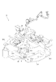
- the side view which shows the construction machine which concerns on one Embodiment of this invention The perspective view which shows the vehicle body frame of a construction machine.
- FIG. 1 is a side view showing a hydraulic excavator 1 as a construction machine according to the present embodiment.
- a hydraulic excavator 1 includes a crawler type lower traveling body 2 driven by a hydraulic motor, an upper revolving body 3 that is pivotably provided on an upper portion of the lower traveling body 2, and a front side of the upper revolving body 3.
- a work machine 4 provided on the side for excavating earth and sand and an electrical component unit 5 in which a plurality of electrical components are unitized are configured as a small hydraulic excavator.
- the lower traveling unit 2 includes a track frame 21.
- the track frame 21 is disposed on both sides of the center frame 22 with the center frame 22 on which the upper swing body 3 is pivotably mounted and spaced in the vehicle width direction, and the crawler 24 is wound around the outer periphery. And a pair of crawler frames 23.
- the upper swing body 3 includes a revo frame 31 as a vehicle body frame provided with a swing hydraulic motor (not shown) at a substantially central position.
- the working machine 4 a cab 32 on which an operator gets on, and a counterweight 33 are arranged in order from the front side to the rear side.
- the cab 32 is configured to be tiltable with respect to the revo frame 31 with the front end side as a fulcrum as shown by a two-dot chain line in FIG.
- the revo frame 31 is provided with a canopy 34 that covers the cab 32 from above.
- the canopy 34 includes a pair of pillars 34A erected on the left and right sides, and a roof 34B supported by the upper ends of the pillars 34A.
- the lower end of the column 34 ⁇ / b> A is supported by the upper surfaces of the left and right ends of the counterweight 33.
- front, rear, left, and right are directions based on an operator seated on the cab 32.
- a hydraulic pump (not shown) driven by an engine, and a control (not shown) that distributes the pressure oil pumped from the hydraulic pump to the lower traveling body 2 and the work implement 4.
- EPC electromechanical proportional control
- valve 35 for controlling the pilot pressure of the valve and the control valve
- an accumulator 36 for accumulating pressure oil
- a vehicle body controller 37 for controlling them FIG. 2
- tanks (not shown) such as a fuel tank, a hydraulic oil tank, and a sub-tank for engine cooling water are arranged, and a battery 38 (FIG. 2) is located behind these tanks. Has been placed.
- the work machine 4 includes a boom 41 attached to the revo frame 31 so as to swing up and down, an arm (not shown) attached to the tip of the boom 41 so as to swing up and down, and attached to the tip of the arm so as to swing up and down. And an unillustrated bucket.
- the boom 41, the arm, and the bucket are respectively connected to the tip of the cylinder rod of the boom cylinder 41A, which is a hydraulic cylinder, the arm cylinder, and the bucket cylinder, and each cylinder rod is expanded and contracted by pressure oil from a control valve (not shown). Oscillates when operated.
- a blade 42 is provided at the front of the track frame 21 of the lower traveling body 2 as another working machine.
- the blade 42 is operated by a blade cylinder (not shown).
- the blade cylinder also expands and contracts with the pressure oil from the control valve.
- FIG. 2 is a perspective view showing the revo frame 31.
- the revo frame 31 includes a bottom plate 311, a pair of main frames 312 erected on the bottom plate 311, a cross member 313 erected on the bottom plate 311 so as to intersect the main frame 312, and a pair of main frames
- An upper plate 314 spanned between the upper ends of the frame 312 and a first support frame 315 and a second support frame 316 as support frames that support the cab 32 in a tiltable manner are provided.
- the pair of main frames 312 are arranged so that the rear end sides thereof are positioned in parallel with each other and the interval between the rear end sides decreases from the rear end side toward the front end side.
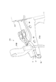
- the first support frame 315 is provided on the upper surface of the extending portion 315A extending from the left main frame 312 toward the vehicle width direction outer side and the extending portion 315A.
- a support portion 315 ⁇ / b> B that pivotally supports 32.
- the extending portion 315A has a U-shaped cross-sectional shape opened downward, and the electrical component unit 5 is accommodated in a space S formed by the U-shape.
- the support portion 315B is formed in an L shape and pivotally supports the front end portion of the cab 32 at the standing portion.
- the second support frame 316 is erected at a position on the right main frame 312 side of the upper plate 314 and pivotally supports the front end portion of the cab 32.
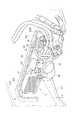
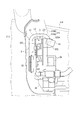
- [Electrical component unit] 4 and 5 are a perspective view and a side view showing the electrical component unit 5.
- the electrical component unit 5 includes a register 51 as an electrical component, a horn 52 as an electrical component, and an attachment member 53.
- the register 51 and the horn 52 are attached to the attachment member 53 as a unit. It is a thing.
- the register 51 is a redundant circuit for causing the hydraulic pump to function when the vehicle body controller 37 fails, and is a controller that limits the current flowing through the hydraulic pump.
- a hydraulic pump is connected to the battery 38 via the register 51.
- the resistor 51 is a resistor, and converts a part of electric power sent from the battery 38 to the hydraulic pump into thermal energy and releases it.
- the attachment member 53 includes a flat plate portion 531, a bent portion 532 bent with respect to the flat plate portion 531, and a stay 533 provided on one surface of the flat plate portion 531.
- the flat plate portion 531 and the bent portion 532 are configured by a plate-like member having bent end portions, and are integrally formed with each other.
- the register 51 and the wiring connector 54 are fixed to the surface of the flat plate portion 531 on the stay 533 side.
- the connector 54 is fixed at a position on the bent portion 532 side with the stay 533 interposed therebetween, and the register 51 is fixed at a position on the opposite side of the bent portion 532.
- the bent portion 532 is bent to the opposite side (rear side) from the stay 533.
- the bent portion 532 has an attachment hole 532A for attaching the wiring holding bracket 55, and holds the wiring via the bracket 55.
- the stay 533 is formed of a member obtained by bending a plate-like member in a step shape.
- the stay 533 is welded to the flat plate portion 531 at one end side in the step direction in a state where the direction in which the steps are arranged (step direction) is directed in the vertical direction.
- the other end side of the stay 533 is disposed in front of the flat plate portion 531 with a space therebetween, and the horn 52 is fixed to the other end side.
- the electrical component unit 5 is accommodated in a space S surrounded by the extending portion 315 ⁇ / b> A of the first support frame 315, and the mounting member 53 is fixed to the extending portion 315 ⁇ / b> A with a bolt 56. ing. At this time, the electrical component unit 5 is covered with the first support frame 315 at the front, upper, and rear. Further, since the register 51 is located above the horn 52, that is, the uppermost electrical component of the electrical component unit 5, even if the heat generated in the register 51 rises, the heat is transmitted to the lower horn 52. Can be prevented.
- the horn 52 is located below the lower end of the first support frame 315 and is exposed to the outside of the space S formed by the first support frame 315.
- the attachment member 53 has a bent portion 532 located outside the tip of the extending portion 315A of the first support frame 315 and is exposed to the outside of the space S. For this reason, the wiring holding bracket 55 can be attached to the bent portion 532, and the bent portion 532 can hold the wiring via the bracket 55.
- the present invention is not limited to the above-described embodiments, and modifications, improvements, and the like within the scope that can achieve the object of the present invention are included in the present invention.
- the horn 52 is exposed outside the space S formed by the first support frame 315 and a part of the electrical component unit 5 is accommodated in the space S. You may accommodate in the space S.
- the electrical component unit 5 is accommodated in the space S surrounded by the first support frame 315.
- the electrical component unit 5 may be accommodated in a space surrounded by another support frame.
- the second support frame may be configured in the same manner as the first support frame 315, and the electrical component unit 5 may be accommodated in a space surrounded by the second support frame.
- the extending portion 315A of the first support frame 315 opens downward, but may open upward, horizontally, or in other directions.
- the support frame is formed in a U shape.
- the support frame may have another shape as long as it has a space surrounded by the support frame.
- the support frame is formed in a hollow shape. And you may accommodate the electrical equipment unit 5 in the hollow space.
- the electrical component unit 5 has a configuration in which the register 51 and the horn 52 are unitized.
- another electrical component may be unitized.
- the electrical component unit 5 may be unitized by attaching another electrical component to the electrical component, instead of unitizing the plurality of electrical components to the attachment member.
- the electrical component unit 5 includes the register 51 as a controller, it may be another controller, for example, a vehicle body controller 37.
- the resistor 51 is constituted by a resistor, but may be an electronic control type.
- the attachment member 53 may have another shape as long as a plurality of electrical components can be attached.
- the attachment member 53 may have a tongue piece extending downward from the lower end of the flat plate portion 531, and the tongue piece may be a stay.
- the horn 52 may be fixed to the flat plate portion 531.
- the bent portion 532 may be bent to the same side (front side) as the stay 533.
- the construction machine is not limited to a hydraulic excavator as long as it has a support frame that pivotally supports a driver's cab, and may be a dump truck, for example.
- the present invention can be used not only for construction machines but also for other mobile machines configured to be able to tilt the cab relative to the body frame.
- SYMBOLS 1 Hydraulic excavator (construction machine), 5 ... Electrical component unit, 31 ... Revo frame (body frame), 32 ... Driver's cab, 51 ... Register (electric component, controller), 52 ... Horn (electric component), 315 ... First 1 support frame (support frame), S ... space.
Landscapes
- Engineering & Computer Science (AREA)
- Mining & Mineral Resources (AREA)
- Civil Engineering (AREA)
- General Engineering & Computer Science (AREA)
- Structural Engineering (AREA)
- Body Structure For Vehicles (AREA)
Abstract
Description
また、このような建設機械において、複数の電装品をまとめてユニット化したものを収容する構造が知られている(例えば、特許文献2参照)。
しかしながら、車体フレームには、エンジンや燃料タンク等の大型の機器が搭載されるため、電装品の配置スペースが十分でないという問題がある。
本発明の建設機械において、前記電装品ユニットは、複数の電装品を取付部材に取り付けてユニット化され、前記複数の電装品のうち少なくとも1つはコントローラであり、前記コントローラは、前記複数の電装品のうち最も上方に配置されていることが好ましい。
本発明の建設機械において、前記複数の電装品は、少なくとも1つがホーンであり、前記ホーンは、前記空間の外部に露出していることが好ましい。
以下、本発明の一実施形態を図面に基づいて説明する。
図1は、本実施形態に係る建設機械としての油圧ショベル1を示す側面図である。
図1において、油圧ショベル1は、油圧モータにて駆動されるクローラ式の下部走行体2と、下部走行体2の上部に旋回自在に設けられた上部旋回体3と、上部旋回体3の前方側に設けられて土砂の掘削等を行う作業機4と、複数の電装品をユニット化した電装品ユニット5とを備え、小型の油圧ショベルとして構成されている。
図2は、レボフレーム31を示す斜視図である。
図2において、レボフレーム31は、底板311と、底板311に立設された一対のメインフレーム312と、底板311にメインフレーム312と交差するように立設されたクロスメンバ313と、一対のメインフレーム312の上端間に架け渡された上板314と、運転台32をチルト可能に支持する支持フレームとしての第1支持フレーム315および第2支持フレーム316とを備えている。
第1支持フレーム315は、図3にも示すように、左側のメインフレーム312から車幅方向外側に向かって延設された延設部315Aと、延設部315Aの上面に設けられ、運転台32を軸支する支持部315Bとを備えている。延設部315Aは、下方に開口したU字状の断面形状を有し、当該U字形状により形成された空間Sに電装品ユニット5が収容されている。支持部315Bは、L字状に形成され、その立設部で運転台32の前端部を軸支する。
第2支持フレーム316は、上板314における右側のメインフレーム312側の位置に立設され、運転台32の前端部を軸支する。
図4および図5は、電装品ユニット5を示す斜視図および側面図である。
図4、図5において、電装品ユニット5は、電装品としてのレジスタ51と、電装品としてのホーン52と、取付部材53とを備え、取付部材53にレジスタ51およびホーン52を取り付けてユニット化したものである。
平板部531および屈曲部532は、端部を屈曲させた板状の部材で構成され、互いが一体成形されている。
平板部531のステイ533側の面には、レジスタ51や配線用のコネクタ54が固定されている。本実施形態では、ステイ533を挟んで屈曲部532側の位置にコネクタ54が固定され、屈曲部532の反対側の位置にレジスタ51が固定されている。
屈曲部532は、ステイ533とは反対側(後方側)に屈曲している。この屈曲部532は、配線保持用のブラケット55を取り付ける取付孔532Aを有し、当該ブラケット55を介して配線を保持する。
ステイ533は、板状部材を階段状に屈曲させた部材で形成されている。このステイ533は、段差の並び方向(段差方向)を上下方向に向けた状態で、段差方向の一端側が平板部531に溶接されている。ステイ533の他端側は、平板部531の前方に間隔を空けて配置され、当該他端側にホーン52が固定されている。
図3から図5に示すように、電装品ユニット5は、第1支持フレーム315の延設部315Aで囲まれた空間Sに収容され、取付部材53が延設部315Aにボルト56で固定されている。このとき、電装品ユニット5は、その前方、上方、および後方が第1支持フレーム315で覆われている。また、レジスタ51がホーン52よりも上方、すなわち、電装品ユニット5の電装品のうち最も上方に位置するため、レジスタ51で発生した熱が上昇しても、下方のホーン52に熱が伝わることを防止できる。
また、取付部材53は、屈曲部532が第1支持フレーム315の延設部315Aの先端よりも外側に位置し、空間Sの外部に露出している。このため、屈曲部532に配線保持用のブラケット55取り付けることができ、当該ブラケット55を介して屈曲部532に配線を保持させることができる。
以上に説明した本実施形態によれば、以下の効果がある。
すなわち、電装品ユニット5の少なくとも一部は、第1支持フレーム315で囲まれた空間Sに収容されているため、レボフレーム31のスペースを有効利用し、レボフレーム31における電装品の配置スペースを確保することができる。
なお、本発明は前述の実施形態に限定されるものではなく、本発明の目的を達成できる範囲での変形、改良等は本発明に含まれるものである。
例えば、前記実施形態では、第1支持フレーム315で形成される空間Sの外部にホーン52を露出させ、電装品ユニット5の一部を空間Sに収容していたが、電装品ユニット5全体を空間Sに収容してもよい。
前記実施形態では、第1支持フレーム315の延設部315Aが下方に開口していたが上方、水平方向その他の方向に開口してもよい。
前記実施形態では、支持フレームは、U字状に形成されていたが、支持フレームで囲まれた空間を有するものであれば他の形状であってもよく、例えば、支持フレームを中空状に形成し、その中空空間に電装品ユニット5を収容してもよい。
前記実施形態では、レジスタ51は、抵抗器で構成されていたが、電子制御式のものであってもよい。
例えば、取付部材53は、平板部531の下端から下方に延設した舌片部を有し、当該舌片部をステイとしてもよい。また、平板部531にホーン52を固定してもよい。
また、屈曲部532は、ステイ533と同じ側(前方側)に屈曲してもよい。
Claims (4)
- 車体フレームと、
電装品ユニットとを備え、
前記車体フレームは、運転台を軸支する支持フレームを備え、
前記電装品ユニットの少なくとも一部は、前記支持フレームで囲まれた空間に収容されていることを特徴とする建設機械。 - 請求項1に記載の建設機械において、
前記支持フレームは、U字状の断面形状を有し、当該U字形状により前記空間を形成することを特徴とする建設機械。 - 請求項2に記載の建設機械において、
前記電装品ユニットは、複数の電装品を取付部材に取り付けてユニット化され、
前記複数の電装品のうち少なくとも1つはコントローラであり、
前記コントローラは、前記複数の電装品のうち最も上方に配置されていることを特徴とする建設機械。 - 請求項2または請求項3に記載の建設機械において、
前記複数の電装品は、少なくとも1つがホーンであり、
前記ホーンは、前記空間の外部に露出していることを特徴とする建設機械。
Priority Applications (4)
| Application Number | Priority Date | Filing Date | Title |
|---|---|---|---|
| DE112015000230.8T DE112015000230B4 (de) | 2015-12-18 | 2015-12-18 | Baumaschine |
| PCT/JP2015/085585 WO2016108271A1 (ja) | 2015-12-18 | 2015-12-18 | 建設機械 |
| JP2016533679A JP6145578B2 (ja) | 2015-12-18 | 2015-12-18 | 建設機械 |
| CN201580003353.XA CN107075836B (zh) | 2015-12-18 | 2015-12-18 | 建筑机械 |
Applications Claiming Priority (1)
| Application Number | Priority Date | Filing Date | Title |
|---|---|---|---|
| PCT/JP2015/085585 WO2016108271A1 (ja) | 2015-12-18 | 2015-12-18 | 建設機械 |
Publications (1)
| Publication Number | Publication Date |
|---|---|
| WO2016108271A1 true WO2016108271A1 (ja) | 2016-07-07 |
Family
ID=56284425
Family Applications (1)
| Application Number | Title | Priority Date | Filing Date |
|---|---|---|---|
| PCT/JP2015/085585 Ceased WO2016108271A1 (ja) | 2015-12-18 | 2015-12-18 | 建設機械 |
Country Status (4)
| Country | Link |
|---|---|
| JP (1) | JP6145578B2 (ja) |
| CN (1) | CN107075836B (ja) |
| DE (1) | DE112015000230B4 (ja) |
| WO (1) | WO2016108271A1 (ja) |
Cited By (1)
| Publication number | Priority date | Publication date | Assignee | Title |
|---|---|---|---|---|
| WO2017183287A1 (ja) * | 2016-04-20 | 2017-10-26 | 株式会社日立建機ティエラ | 小型油圧ショベル |
Families Citing this family (1)
| Publication number | Priority date | Publication date | Assignee | Title |
|---|---|---|---|---|
| JP7848070B2 (ja) * | 2022-07-14 | 2026-04-20 | ヤンマーホールディングス株式会社 | 建設機械 |
Citations (10)
| Publication number | Priority date | Publication date | Assignee | Title |
|---|---|---|---|---|
| JPS54176914U (ja) * | 1978-06-01 | 1979-12-14 | ||
| JPS6268881U (ja) * | 1985-10-21 | 1987-04-30 | ||
| JPH07187589A (ja) * | 1993-12-27 | 1995-07-25 | Toyota Autom Loom Works Ltd | 産業車両のステップ構造 |
| WO2004076265A1 (ja) * | 2003-02-27 | 2004-09-10 | Komatsu Ltd. | 後端小旋回油圧ショベル |
| JP2005113426A (ja) * | 2003-10-03 | 2005-04-28 | Kubota Corp | 旋回作業機 |
| JP2007205120A (ja) * | 2006-02-06 | 2007-08-16 | Kobelco Contstruction Machinery Ltd | 建設機械のアッパーフレーム |
| JP2009533277A (ja) * | 2006-04-12 | 2009-09-17 | ストラテック・セキュリティー・コーポレーション | トランスポンダ認証システムおよび方法 |
| JP2010180578A (ja) * | 2009-02-04 | 2010-08-19 | Sumitomo (Shi) Construction Machinery Co Ltd | 建設機械の警報装置 |
| JP2013121871A (ja) * | 2011-12-12 | 2013-06-20 | Tcm Corp | 産業車両又は建設車両の電装品、電気配線及び油圧配管の固定具 |
| JP2013237985A (ja) * | 2012-05-11 | 2013-11-28 | Hitachi Constr Mach Co Ltd | 建設機械 |
Family Cites Families (7)
| Publication number | Priority date | Publication date | Assignee | Title |
|---|---|---|---|---|
| KR100666585B1 (ko) * | 2003-09-10 | 2007-01-09 | 히다치 겡키 가부시키 가이샤 | 건설기계 |
| US20070131466A1 (en) * | 2005-12-12 | 2007-06-14 | Gutzwiller Timothy M | Work machine with electrical and hydraulic service centers |
| JP4142692B2 (ja) * | 2006-02-07 | 2008-09-03 | 株式会社竹内製作所 | 作業車のバッテリ配置構造 |
| JP4890929B2 (ja) | 2006-05-01 | 2012-03-07 | キャタピラー エス エー アール エル | 作業機械の電装品収納構造 |
| JP5184821B2 (ja) | 2007-06-06 | 2013-04-17 | 株式会社小松製作所 | 作業車両のヒンジ構造 |
| DE102013106141B4 (de) * | 2013-06-13 | 2024-05-16 | Dr. Ing. H.C. F. Porsche Aktiengesellschaft | Lagerrahmen für ein elektrisch angetriebenes Kraftfahrzeug |
| JP5854024B2 (ja) * | 2013-10-31 | 2016-02-09 | コベルコ建機株式会社 | 建設機械 |
-
2015
- 2015-12-18 JP JP2016533679A patent/JP6145578B2/ja active Active
- 2015-12-18 WO PCT/JP2015/085585 patent/WO2016108271A1/ja not_active Ceased
- 2015-12-18 DE DE112015000230.8T patent/DE112015000230B4/de not_active Expired - Fee Related
- 2015-12-18 CN CN201580003353.XA patent/CN107075836B/zh not_active Expired - Fee Related
Patent Citations (10)
| Publication number | Priority date | Publication date | Assignee | Title |
|---|---|---|---|---|
| JPS54176914U (ja) * | 1978-06-01 | 1979-12-14 | ||
| JPS6268881U (ja) * | 1985-10-21 | 1987-04-30 | ||
| JPH07187589A (ja) * | 1993-12-27 | 1995-07-25 | Toyota Autom Loom Works Ltd | 産業車両のステップ構造 |
| WO2004076265A1 (ja) * | 2003-02-27 | 2004-09-10 | Komatsu Ltd. | 後端小旋回油圧ショベル |
| JP2005113426A (ja) * | 2003-10-03 | 2005-04-28 | Kubota Corp | 旋回作業機 |
| JP2007205120A (ja) * | 2006-02-06 | 2007-08-16 | Kobelco Contstruction Machinery Ltd | 建設機械のアッパーフレーム |
| JP2009533277A (ja) * | 2006-04-12 | 2009-09-17 | ストラテック・セキュリティー・コーポレーション | トランスポンダ認証システムおよび方法 |
| JP2010180578A (ja) * | 2009-02-04 | 2010-08-19 | Sumitomo (Shi) Construction Machinery Co Ltd | 建設機械の警報装置 |
| JP2013121871A (ja) * | 2011-12-12 | 2013-06-20 | Tcm Corp | 産業車両又は建設車両の電装品、電気配線及び油圧配管の固定具 |
| JP2013237985A (ja) * | 2012-05-11 | 2013-11-28 | Hitachi Constr Mach Co Ltd | 建設機械 |
Cited By (2)
| Publication number | Priority date | Publication date | Assignee | Title |
|---|---|---|---|---|
| WO2017183287A1 (ja) * | 2016-04-20 | 2017-10-26 | 株式会社日立建機ティエラ | 小型油圧ショベル |
| US11142882B2 (en) | 2016-04-20 | 2021-10-12 | Hitachi Construction Machinery Tierra Co., Ltd | Small hydraulic excavator |
Also Published As
| Publication number | Publication date |
|---|---|
| CN107075836B (zh) | 2021-11-02 |
| JPWO2016108271A1 (ja) | 2017-04-27 |
| DE112015000230T5 (de) | 2016-08-18 |
| DE112015000230B4 (de) | 2022-06-30 |
| JP6145578B2 (ja) | 2017-06-14 |
| CN107075836A (zh) | 2017-08-18 |
Similar Documents
| Publication | Publication Date | Title |
|---|---|---|
| JP4987644B2 (ja) | 建設機械の運転室を支持する上部フレーム構造 | |
| JP5106657B1 (ja) | 油圧ショベル | |
| KR20130100995A (ko) | 전동 작업 차량 | |
| KR20060056228A (ko) | 선회 작업기 | |
| KR20240009870A (ko) | 건설 기계 | |
| JP5810821B2 (ja) | 建設機械のアッパーフレーム | |
| US9745717B2 (en) | Construction machine | |
| JP2004162405A (ja) | 運転室のフロア構造 | |
| JP6145578B2 (ja) | 建設機械 | |
| JP5491945B2 (ja) | トラクタ | |
| JP5984497B2 (ja) | 運転室昇降装置 | |
| JP4984923B2 (ja) | 建設機械のアッパーフレーム | |
| EP2813624B1 (en) | Cable and hose support and guide for construction machine | |
| JP4199173B2 (ja) | 旋回式建設機械 | |
| JP2007063839A (ja) | 建設機械用保護構造物及び建設機械用キャブ | |
| JP6361677B2 (ja) | 建設機械の配管構造 | |
| JP5156294B2 (ja) | 建設機械のメインフレームおよびこれを備えた建設機械 | |
| JP5202581B2 (ja) | 旋回作業機 | |
| JP4798985B2 (ja) | 旋回作業機 | |
| JP7772727B2 (ja) | 作業用車両 | |
| JP2008149937A (ja) | ホイールローダ | |
| JP4459027B2 (ja) | 旋回作業機 | |
| JP6908567B2 (ja) | 建設機械 | |
| JP2538210Y2 (ja) | 建設機械のスイングフレーム | |
| JPWO2016108274A1 (ja) | 油圧ショベル |
Legal Events
| Date | Code | Title | Description |
|---|---|---|---|
| ENP | Entry into the national phase |
Ref document number: 2016533679 Country of ref document: JP Kind code of ref document: A |
|
| WWE | Wipo information: entry into national phase |
Ref document number: 112015000230 Country of ref document: DE |
|
| 121 | Ep: the epo has been informed by wipo that ep was designated in this application |
Ref document number: 15875397 Country of ref document: EP Kind code of ref document: A1 |
|
| 122 | Ep: pct application non-entry in european phase |
Ref document number: 15875397 Country of ref document: EP Kind code of ref document: A1 |