WO2016104246A1 - リアクトル - Google Patents
リアクトル Download PDFInfo
- Publication number
- WO2016104246A1 WO2016104246A1 PCT/JP2015/085047 JP2015085047W WO2016104246A1 WO 2016104246 A1 WO2016104246 A1 WO 2016104246A1 JP 2015085047 W JP2015085047 W JP 2015085047W WO 2016104246 A1 WO2016104246 A1 WO 2016104246A1
- Authority
- WO
- WIPO (PCT)
- Prior art keywords
- reactor
- sensor arrangement
- inner core
- core
- arrangement groove
- Prior art date
- Legal status (The legal status is an assumption and is not a legal conclusion. Google has not performed a legal analysis and makes no representation as to the accuracy of the status listed.)
- Ceased
Links
Images


Classifications
-
- H—ELECTRICITY
- H01—ELECTRIC ELEMENTS
- H01F—MAGNETS; INDUCTANCES; TRANSFORMERS; SELECTION OF MATERIALS FOR THEIR MAGNETIC PROPERTIES
- H01F27/00—Details of transformers or inductances, in general
- H01F27/40—Structural association with built-in electric component, e.g. fuse
- H01F27/402—Association of measuring or protective means
-
- G—PHYSICS
- G01—MEASURING; TESTING
- G01K—MEASURING TEMPERATURE; MEASURING QUANTITY OF HEAT; THERMALLY-SENSITIVE ELEMENTS NOT OTHERWISE PROVIDED FOR
- G01K1/00—Details of thermometers not specially adapted for particular types of thermometer
- G01K1/14—Supports; Fastening devices; Arrangements for mounting thermometers in particular locations
-
- G—PHYSICS
- G01—MEASURING; TESTING
- G01K—MEASURING TEMPERATURE; MEASURING QUANTITY OF HEAT; THERMALLY-SENSITIVE ELEMENTS NOT OTHERWISE PROVIDED FOR
- G01K7/00—Measuring temperature based on the use of electric or magnetic elements directly sensitive to heat ; Power supply therefor, e.g. using thermoelectric elements
- G01K7/16—Measuring temperature based on the use of electric or magnetic elements directly sensitive to heat ; Power supply therefor, e.g. using thermoelectric elements using resistive elements
- G01K7/22—Measuring temperature based on the use of electric or magnetic elements directly sensitive to heat ; Power supply therefor, e.g. using thermoelectric elements using resistive elements the element being a non-linear resistance, e.g. thermistor
-
- H—ELECTRICITY
- H01—ELECTRIC ELEMENTS
- H01F—MAGNETS; INDUCTANCES; TRANSFORMERS; SELECTION OF MATERIALS FOR THEIR MAGNETIC PROPERTIES
- H01F27/00—Details of transformers or inductances, in general
- H01F27/24—Magnetic cores
-
- H—ELECTRICITY
- H01—ELECTRIC ELEMENTS
- H01F—MAGNETS; INDUCTANCES; TRANSFORMERS; SELECTION OF MATERIALS FOR THEIR MAGNETIC PROPERTIES
- H01F27/00—Details of transformers or inductances, in general
- H01F27/28—Coils; Windings; Conductive connections
- H01F27/32—Insulating of coils, windings, or parts thereof
- H01F27/324—Insulation between coil and core, between different winding sections, around the coil; Other insulation structures
-
- H—ELECTRICITY
- H01—ELECTRIC ELEMENTS
- H01F—MAGNETS; INDUCTANCES; TRANSFORMERS; SELECTION OF MATERIALS FOR THEIR MAGNETIC PROPERTIES
- H01F37/00—Fixed inductances not covered by group H01F17/00
-
- H—ELECTRICITY
- H01—ELECTRIC ELEMENTS
- H01F—MAGNETS; INDUCTANCES; TRANSFORMERS; SELECTION OF MATERIALS FOR THEIR MAGNETIC PROPERTIES
- H01F27/00—Details of transformers or inductances, in general
- H01F27/40—Structural association with built-in electric component, e.g. fuse
- H01F27/402—Association of measuring or protective means
- H01F2027/406—Temperature sensor or protection
-
- H—ELECTRICITY
- H01—ELECTRIC ELEMENTS
- H01F—MAGNETS; INDUCTANCES; TRANSFORMERS; SELECTION OF MATERIALS FOR THEIR MAGNETIC PROPERTIES
- H01F27/00—Details of transformers or inductances, in general
- H01F27/28—Coils; Windings; Conductive connections
- H01F27/30—Fastening or clamping coils, windings, or parts thereof together; Fastening or mounting coils or windings on core, casing, or other support
- H01F27/306—Fastening or mounting coils or windings on core, casing or other support
Definitions
- the present invention relates to a reactor used for a vehicle-mounted DC-DC converter or a power converter component mounted on an electric vehicle such as a hybrid vehicle.
- Patent Document 1 discloses a reactor used in a converter of a hybrid vehicle.
- Patent Document 1 discloses a combination of a coil having a pair of winding portions and a magnetic core partially disposed inside the winding portion, and a temperature sensor (typically, a physical quantity related to a reactor). , A temperature sensor that measures the temperature of the coil). In this reactor, the temperature sensor is fixed on the upper side of the combined body and at a position between the pair of winding portions. For the fixing, an insulator (insulating intervening member) that secures insulation between the coil and the magnetic core is used. More specifically, a portion (housing portion) where the temperature sensor is arranged is provided in the insulating interposed member, and the position of the temperature sensor is fixed by arranging the temperature sensor in the housing portion.
- a temperature sensor typically, a physical quantity related to a reactor.
- the magnetic core is composed of a composite material containing soft magnetic powder and resin
- the thermal conductivity of the composite material is not so high, and therefore the temperature of the magnetic core tends to increase. If the temperature of the magnetic core becomes too high, the magnetic properties of the magnetic core may be degraded. Therefore, it is desired to accurately measure the temperature of the magnetic core.
- the present invention has been made in view of the above circumstances, and one of its purposes is to provide a reactor capable of accurately measuring the temperature of a magnetic core.
- the reactor which concerns on 1 aspect of this invention is a reactor provided with the assembly which has the coil which has a winding part, and a magnetic core, and the temperature sensor which measures the temperature of a reactor, Comprising: Of the said magnetic core, the said A sensor arrangement groove is formed on the outer peripheral surface of the inner core part inserted into the winding part and is arranged inside the winding part, and the temperature sensor is provided in the sensor arrangement groove.
- the temperature of the magnetic core in the operating reactor can be accurately measured.
- FIG. 3 is a schematic perspective view of a split core different from the split core provided in the combination of FIG. 2. It is an upper perspective view of the reactor of Embodiment 2. It is a disassembled perspective view of the union body with which the reactor of Embodiment 2 is equipped.
- the reactor of ⁇ 1> embodiment is a reactor provided with the assembly which has the coil which has a winding part, and a magnetic core, and the temperature sensor which measures the temperature of a reactor, Comprising: Of the said magnetic core, the said winding A sensor arrangement groove is formed on the outer peripheral surface of the inner core part inserted into the inside of the turning part and arranged inside the winding part, and the temperature sensor is provided in the sensor arrangement groove.
- the temperature of the magnetic core in the operating reactor can be accurately measured. If the temperature of the magnetic core can be accurately monitored, stable operation of the reactor can be ensured based on the monitoring result.
- the above reactor is excellent in productivity. Because the temperature sensor can be arranged at a desired position of the magnetic core simply by arranging the temperature sensor in the sensor arrangement groove, it is not necessary to prepare a special member for determining the position of the temperature sensor in the magnetic core. It is.
- channel can mention the form extended toward the center side in the axial direction of the said winding part.
- the portion of the magnetic core that is hot is the portion of the inner core portion that is covered with the winding portion of the coil that is located at the center in the axial direction of the winding portion.
- the reactor including the sensor arrangement groove that guides the temperature sensor toward the center position the temperature of the magnetic core in the operating reactor can be further accurately monitored, and the reactor is based on the monitoring result. Stable operation can be ensured.
- channel can mention the form currently formed in the surface farthest from the installation object in which the said assembly is installed among the outer peripheral surfaces of the said inner core part.
- the reactor is used by being attached to the installation target such as a cooling base.
- the heat generated in the reactor during operation is released to the installation target, thereby cooling the reactor.
- the surface farthest from the installation target in the inner core portion has a longer heat conduction path to the installation target, it tends to be hotter than the other surfaces. That is, it can be considered that monitoring the temperature at the central position in the axial direction of the winding part on the far surface is substantially equivalent to measuring the maximum temperature of the magnetic core. Therefore, it is preferable to provide a temperature sensor on the far surface and monitor the temperature of the far surface in order to ensure stable operation of the reactor.
- the temperature sensor disposed between the outer peripheral surface of the inner core portion where the sensor disposition groove is formed and the inner peripheral surface of the winding portion, and provided in the sensor disposition groove. And an adhesive sheet for adhering the inner core part and the winding part to each other.
- the relative position between the coil and the magnetic core can be fixed, it is possible to prevent the relative position between the coil and the magnetic core from being shifted due to vibration or the like. Moreover, since the heat generated in the magnetic core can be released to the coil via the adhesive sheet, the heat dissipation of the reactor can be improved. In addition, since the adhesive sheet covers the temperature sensor arranged in the sensor arrangement groove from the outside, it is possible to prevent the temperature sensor from dropping out of the sensor arrangement groove.
- the inner core portion may include a composite material including a soft magnetic powder and a resin.
- the composite material can easily adjust its magnetic properties by adjusting the amount of soft magnetic powder relative to the resin. Therefore, according to the composite material, an inner core portion having desired magnetic characteristics can be easily produced. Since the inner core portion made of the composite material is formed by cast molding, injection molding, or the like, it is easy to form a sensor arrangement groove in the inner core portion.
- the inner core portion includes a magnetic body and an inner resin mold portion formed on a surface of the magnetic body, and the sensor arrangement groove is formed in the inner resin mold portion. Can be mentioned.
- the magnetic path cross-sectional area of the magnetic body that determines the magnetic characteristics of the inner core portion is not reduced. Since it is easy to form the sensor arrangement groove in the inner resin mold part made of resin, the formation of the sensor arrangement groove does not significantly impair the productivity of the inner core part.
- FIG. 1 is an upper perspective view of the reactor 1 ⁇
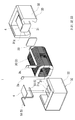
- FIG. 2 is an exploded perspective view of the combined body 1 provided in the reactor 1 ⁇
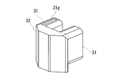
- FIG. 3 is a schematic perspective view of a split core different from the split cores 3A and 3B provided in the combination 1 of FIG.
- reactor 1 has a configuration in which a combined body 1 having a coil 2 and a magnetic core 3 is fixed on a mounting plate 9 with a bonding layer 8.
- the main difference between the reactor 1 ⁇ of this embodiment and the conventional reactor is that a sensor arrangement groove 31g (see FIG. 2) for arranging the temperature sensor 5 is formed in the magnetic core 3 as described later. .
- a sensor arrangement groove 31g for arranging the temperature sensor 5 is formed in the magnetic core 3 as described later.
- the coil 2 in the present embodiment includes a pair of winding portions 2A and 2B and a connecting portion 2R that connects both the winding portions 2A and 2B.
- Each winding part 2A, 2B is formed in a hollow cylindrical shape with the same number of turns and the same winding direction, and is arranged in parallel so that the respective axial directions are parallel.
- the connecting portion 2R is a portion bent in a U shape that connects the two winding portions 2A and 2B.
- the coil 2 may be formed by spirally winding a single winding without a joint.
- the windings 2A and 2B may be formed by separate windings, and the windings 2A and 2B You may form by joining the edge parts of a coil
- Each winding part 2A, 2B of this embodiment is formed in a rectangular tube shape.
- the rectangular tube-shaped winding parts 2A and 2B are winding parts whose end face shape is a square shape (including a square shape) with rounded corners.
- the winding portions 2A and 2B may be formed in a cylindrical shape.
- the cylindrical winding portion is a winding portion whose end face shape is a closed curved surface shape (an elliptical shape, a perfect circle shape, a race track shape, etc.).
- the coil 2 including the winding portions 2A and 2B is a coated wire having an insulating coating made of an insulating material on the outer periphery of a conductor such as a flat wire or a round wire made of a conductive material such as copper, aluminum, magnesium, or an alloy thereof. Can be configured.
- the windings 2A and 2B are formed by edgewise winding a rectangular wire made of copper and a conductor made of enamel (typically polyamideimide). Yes.
- Both end portions 2a and 2b of the coil 2 are extended from the winding portions 2A and 2B and connected to a terminal member (not shown).
- An external device such as a power source for supplying power is connected to the coil 2 through the terminal member.
- the magnetic core 3 in this example is configured by combining a substantially U-shaped first divided core 3 ⁇ / b> A and a second divided core 3 ⁇ / b> B and two gap members 33.
- the first divided core 3A and the second divided core 3B have the same configuration. These divided cores 3A and 3B differ from the prior art in that they have a sensor arrangement groove 31g described later.
- Gap members 33 and 33 are interposed between the tip of the forked portion of the first split core 3A and the tip of the forked portion of the second split core 3B, so that the split cores 3A,
- the annular magnetic core 3 formed by combining 3B can be divided into inner core portions 31 and 31 and outer core portions 32 and 32 for convenience.
- the inner core portion 31 is a portion of the magnetic core 3 that is disposed inside the winding portion 2A (2B) of the coil 2.
- the inner core portion 31 in this example means a portion of the magnetic core 3 that has an axial direction along the axial direction of the winding portions 2A and 2B of the coil 2.
- the portions closer to the winding portions 2A and 2B than the broken lines shown in FIGS. 1 and 2 protrude outside the winding portions 2A and 2B from the end faces of the winding portions 2A and 2B.
- the shape of the inner core portion 31 is a shape along the inner shape of the winding portion 2A (2B), and in the case of this example, is a substantially rectangular parallelepiped shape.
- one inner core portion 31 is formed by one protruding portion of the first divided core 3A, one protruding portion of the second divided core 3B, and the gap member 33 sandwiched between these protruding portions. ing.
- the inner core portion 31 of this example is made of a composite material containing soft magnetic powder and resin.
- Soft magnetic powder is an aggregate of magnetic particles composed of an iron group metal such as iron or an alloy thereof (Fe—Si alloy, Fe—Ni alloy, etc.).
- An insulating coating made of phosphate or the like may be formed on the surface of the magnetic particles.
- the resin include thermosetting resins such as epoxy resin, phenol resin, silicone resin, and urethane resin, polyamide (PA) resin such as polyphenylene sulfide (PPS) resin, nylon 6 and nylon 66, polyimide resin, and fluorine resin.
- a thermoplastic resin such as a resin, a room temperature curable resin, or a low temperature curable resin can be used.
- the inner core portion 31 may be configured to include a magnetic body and an inner resin mold portion formed on the surface thereof.
- the magnetic material include a powder compact formed by press-forming raw material powder containing the soft magnetic powder, and a laminate obtained by laminating magnetic steel plates.
- the resin constituting the inner resin mold part include PPS resin, polytetrafluoroethylene (PTFE) resin, liquid crystal polymer (LCP), nylon 6 and nylon 66, polyamide (PA) resin, and polybutylene terephthalate (PBT) resin.
- Thermoplastic resins such as acrylonitrile / butadiene / styrene (ABS) resin can be used.
- thermosetting resins such as unsaturated polyester resins, epoxy resins, urethane resins, and silicone resins can be used. These resins may contain ceramic fillers such as alumina and silica to improve the heat dissipation of the resin mold part.
- the gap material 33 a non-magnetic material such as ceramics such as alumina or resin such as polypropylene can be used.
- the gap member 33 can be formed of an adhesive that bonds the projecting portions of the two split cores 3A and 3B.
- the outer core portion 32 has a shape that connects the ends of the pair of inner core portions 31 and 31.
- the outer core portion 32 has a trapezoidal column shape.
- the center part in the parallel direction of winding part 2A, 2B in the outer core part 32 protrudes rather than another part.
- the magnetic path cross-sectional area of the central part is substantially the same as the magnetic path cross-sectional area of the inner core part 31 described above.
- the surface of the mounting plate 9 (see FIG. 1) is flush with the surface of the winding portions 2 ⁇ / b> A and 2 ⁇ / b> B of the coil 2 on the mounting plate 9 side. For this reason, the outer core portion 32 comes into contact with the mounting plate 9 via a bonding layer 8 described later.
- the outer core portion 32 may also be formed of a composite material molded body like the inner core portion 31, or may be formed of a magnetic body including an outer resin mold portion. Both the inner core portion 31 and the outer core portion 32 may be made of a composite material or a magnetic material, the inner core portion 31 is made of a composite material, and the outer core portion 32 is made of a magnetic material, or vice versa. You can also. However, as in this example, in the case of the split cores 3A and 3B configured by the outer core portion 32 and a part of the pair of inner core portions 31 and 31, the inner core portion 31 and the outer core portion 32 are the same. Consists of materials.
- Each of the first divided core 3A and the second divided core 3B includes a sensor arrangement groove 31g at the position of the protruding portion arranged on the left side of the drawing when the outer core portion 32 is directed to the front side of the drawing.
- the sensor arrangement groove 31g formed in the first division core 3A is used among the two sensor arrangement grooves 31g formed in the division cores 3A and 3B.
- the sensor arrangement groove 31g of the second divided core 3B may also be used.
- the reason why both the split cores 3A and 3B have the sensor arrangement grooves 31g is that both split cores 3A and 3B are manufactured with the same mold in order to improve productivity.
- the sensor arrangement groove 31g extends from the position of the end surface of the winding portion 2A (2B) in the axial direction of the winding portion 2A (2B). It only needs to extend toward the center.
- the extending direction of the sensor arrangement groove 31g is preferably along the axial direction of the winding portion 2A (2B), but may be inclined with respect to the axial direction.
- the sensor arrangement groove 31g of this example extends in the direction along the axial direction of the protruding portion (the axial direction of the inner core portion 31) on the upper surface of the protruding portion that becomes the inner core portion 31 of the first divided core 3A. And it is formed over the full length of a protrusion part.
- the sensor arrangement groove 31g is formed between the inner core portion 31 and the outer side. From the vicinity of the boundary with the core portion 32, it reaches the center in the axial direction of the inner core portion 31 (the center in the axial direction of the winding portion 2 ⁇ / b> A).
- the sensor arrangement groove 31g may be shorter than the axial length of the protruding portion, but it is preferable that the tip thereof reaches the end of the protruding portion of the first split core 3A. By doing so, a portion of the temperature sensor 5 to be described later that actually measures the temperature can be guided to the center of the inner core portion 31 in the axial direction.
- the tip of the sensor placement groove 31 g may not reach the end of the protruding portion of the split core. In the configuration of FIG. 3 as well, if the position of the tip of the sensor placement groove 31g is close to the end of the projecting portion, the tip of the temperature sensor 5 placed in the sensor placement groove 31g is moved in the axial direction of the inner core portion 31. It can be led near the center.
- the cross-sectional shape and the size of the sensor arrangement groove 31g can be appropriately selected according to the size of the temperature sensor 5 arranged in the sensor arrangement groove 31g.
- the size of the sensor arrangement groove 31g may be a size that allows the temperature sensor 5 to be accommodated therein, or may be a size that allows the temperature sensor 5 arranged in the sensor arrangement groove 31g to slightly protrude from the sensor arrangement groove 31g. . Regardless of the size of the sensor arrangement groove 31g, the position of the temperature sensor 5 in the inner core portion 31 can be determined.
- the sensor arrangement groove 31g of this example is formed on the upper surface (the upper surface in FIG. 2) of the inner core portion 31, but may be provided on the side surface or the lower surface.
- the sensor placement groove 31g is preferably formed on a surface (in this example, an upper surface) farthest from the installation target of the reactor 1 ⁇ among the plurality of surfaces constituting the inner core portion 31. Since the heat generated in the reactor 1 ⁇ is released to the installation target, the temperature on the installation target side in the reactor 1 ⁇ tends to be lower than the temperature on the opposite side. That is, the surface (upper surface in this example) farthest from the installation target, which is the heat dissipation path, of the inner core portion 31 is likely to be hotter than the other surfaces. If the temperature of the portion that is likely to be the highest temperature can be measured, the operation of the reactor 1 ⁇ can be managed so that the entire reactor 1 ⁇ (FIG. 1) does not exceed a predetermined temperature.
- the sensor placement groove 31g used for actually placing the temperature sensor 5 is a sensor placement groove at a position where the wiring portion 51 of the temperature sensor 5 is easily pulled out.
- the position on the winding part 2A side where the winding bent part is arranged on the connecting part 2R side of the coil 2 is a position where it is difficult to pull out the wiring part 51. Therefore, in this example, the temperature sensor 5 is arrange
- the sensor arrangement groove 31g on the winding part 2B side in the second divided core 3B can also be used.
- the temperature sensor 5 includes a sensor main body 50 in which the outer periphery of a thermosensitive element such as a thermistor is covered with a protective body, and a wiring unit 51 for transmitting information on the measured temperature to an external device such as a control device.
- Reactor 1 ⁇ is controlled based on the measurement information of temperature sensor 5. For example, when the value measured by the temperature sensor 5 is equal to or greater than a predetermined value, the reactor 1 ⁇ may be broken. In this case, control is performed such that the operation of the reactor 1 ⁇ is stopped.
- the temperature sensor 5 is arranged in a sensor arrangement groove 31g formed in the inner core portion 31 of the magnetic core 3.
- the tip of the sensor body 50 (that is, the part that actually measures the temperature) is disposed at the end of the sensor arrangement groove 31g on the gap member 33 side (that is, the center in the axial direction of the inner core portion 31). As described above, this part is a part where the temperature is likely to be highest.
- the reactor 1 ⁇ according to the first embodiment includes the adhesive sheet 4 illustrated in FIG. 2, the mounting plate 9, the bonding layer 8, and the like illustrated in FIG.
- the adhesive sheet 4 is disposed between the outer peripheral surface of the inner core portion 31 and the inner peripheral surfaces of the winding portions 2A and 2B, and the inner core portion 31 and the winding portions 2A and 2B are connected to each other. It is a member to be bonded. Since the relative position between the coil 2 and the magnetic core 3 can be fixed by the adhesive sheet 4, it is possible to prevent the relative position between the coil 2 and the magnetic core 3 from being shifted due to vibration or the like. Here, in the illustrated example, it is provided on the upper surface of the protruding portion provided in each of the split cores 3A and 3B. Although not shown, an adhesive sheet may be disposed on the side surface and the lower surface of the protruding portion.
- the adhesive sheet 4 attached to the portion where the temperature sensor 5 is arranged covers the temperature sensor 5 arranged in the sensor arrangement groove 31g from the outside. For this reason, the adhesive sheet 4 can prevent the temperature sensor 5 from dropping from the sensor placement groove 31g.
- the adhesive sheet 4 can be composed of a sticky insulating resin, for example, a thermosetting resin such as an epoxy resin, a silicone resin, or an unsaturated polyester, or a thermoplastic resin such as a PPS resin or LCP.
- the thermal conductivity of the adhesive sheet 4 may be improved by adding the above-described ceramic filler to these insulating resins. If the thermal conductivity of the adhesive sheet 4 is improved, the adhesive sheet 4 can be effectively used as a heat dissipation path from the magnetic core 3 to the coil 2.
- the thermal conductivity of the adhesive sheet 4 is preferably 0.1 W / m ⁇ K or more, more preferably 1 W / m ⁇ K or more, and particularly preferably 2 W / m ⁇ K or more.
- the adhesive sheet 4 can also be made of foamed resin.
- the adhesive sheet 4 made of foamed resin it is easy to insert the protruding portions of the split cores 3A and 3B into the winding portions 2A and 2B after the adhesive sheet 4 is attached to the split cores 3A and 3B.
- the coil 2 and the magnetic core 3 can be fixed by inserting the protruding portion into the winding portions 2A and 2B and then foaming the foamed resin.
- the mounting plate 9 (FIG. 1) is a member that functions as a base when the reactor 1 ⁇ is fixed to an installation target such as a cooling base. For this reason, the mounting plate 9 is required to have excellent mechanical strength. Further, the mounting plate 9 is required to play a role of releasing heat generated in the assembly 1 to the installation target when the reactor 1 ⁇ is used. Therefore, the mounting plate 9 is required to have excellent heat dissipation in addition to mechanical strength. In order to meet such a demand, the mounting plate 9 is made of metal. For example, aluminum or an alloy thereof, magnesium or an alloy thereof can be used as a constituent material of the mounting plate 9. These metals (alloys) have the advantage of being excellent in mechanical strength and thermal conductivity, lightweight and non-magnetic.
- a bonding layer 8 is formed between the mounting plate 9 and the assembly 1 to join the plates 1 and 9 together.
- the bonding layer 8 also has a function of conducting heat generated in the combined body 1 to the mounting plate 9 when the reactor 1 ⁇ is used.
- the constituent material of the bonding layer 8 is assumed to have insulating properties.
- thermosetting resins such as epoxy resins, silicone resins, and unsaturated polyesters
- thermoplastic resins such as PPS resins and LCPs
- the thermal conductivity of the bonding layer 8 is preferably, for example, 0.1 W / m ⁇ K or more, more preferably 1 W / m ⁇ K or more, and particularly preferably 2 W / m ⁇ K or more.
- the bonding layer 8 may be formed by applying an insulating resin (ceramic filler-containing resin may be used) on the mounting plate 9, or affixing a sheet material of the insulating resin on the mounting plate 9. May be formed. It is preferable to use a sheet-like material as the bonding layer 8 because the bonding layer 8 can be easily formed on the mounting plate 9.
- an insulating resin ceramic filler-containing resin may be used
- the reactor 1 ⁇ described above can accurately measure the temperature of the magnetic core 3 during its operation.
- the temperature sensor 5 monitors the temperature of the magnetic core 3 where the temperature is most likely to rise, the temperature of the magnetic core 3 increases as the magnetic characteristics of the reactor 1 ⁇ decrease. Before this, it is possible to take measures such as stopping the operation of the reactor 1 ⁇ .
- the reactor 1 ⁇ of this example has a configuration in which the assembly 1 formed in a substantially rectangular parallelepiped shape is disposed on the mounting plate 9 via the bonding layer 8.
- the difference between the reactor 1 ⁇ and the reactor 1 ⁇ of the first embodiment is the shapes of the coil 2 and the magnetic core 3 constituting the combined body 1.
- each structure of the reactor 1 ⁇ will be described focusing on differences from the first embodiment.
- the coil 2 provided in the combined body 1 includes one winding part 2 ⁇ / b> C.
- the end 2b of the coil 2 is routed to the end 2a side and drawn out in the same direction as the end 2a.
- the magnetic core 3 provided in the combined body 1 is configured by combining a substantially E-shaped first divided core 3C and a second divided core 3D with a gap material 33 interposed therebetween.
- the E-shaped middle projecting portion is the inner core portion 31, and the other portion is the outer core portion 32.
- the sensor arrangement groove 31g is formed on the upper surface of the portion that becomes the inner core portion 31 in both the split cores 3C and 3D. Unlike the illustrated example, the sensor arrangement groove 31g may have a length that does not reach the end of the portion that becomes the inner core portion 31.
- the temperature sensor 5 is arranged in the sensor arrangement groove 31g provided in the first divided core 3C.
- the upper surface where the sensor arrangement groove 31g is formed is the surface farthest from the installation target on which the reactor 1 ⁇ is installed.
- the adhesive sheet 4 is attached to the upper surface of the split cores 3C and 3D where the sensor placement groove 31g is formed, and the inner peripheral surface of the winding portion 2C and the outer peripheral surface of the inner core portion 31 are bonded. ing.
- the temperature of the portion of the magnetic core 3 where the temperature is most likely to be monitored can be monitored.
- the magnetic core is configured by combining two split cores, but the magnetic core may be configured by combining three or more split cores.
- the magnetic core 3 may be configured by a pair of columnar core pieces that are the inner core portions 31 and a pair of block core pieces that are the outer core portions 32 ( The number of division is four).
- the magnetic core 3 may be configured by a columnar core piece that becomes the inner core portion 31 and a pair of C-shaped core pieces that become the outer core portions 32 (number of divisions). Is three).
- the sensor arrangement groove 31g is formed in the core piece that becomes the inner core portion 31.
- the case is a bottomed cylindrical member having a bottom plate portion and a side wall portion.
- the bottom plate portion of the case also serves as a mounting plate for mounting the combination.
- a converter case can also be used as a case for storing the combination.
- the bottom plate portion and the side wall portion constituting the case may be an integral member, or may be a member obtained by joining the separately prepared bottom plate portion and the side wall portion later.
- the bottom plate portion and the side wall portion can be made of different materials.
- the bottom plate portion may be made of aluminum or an alloy thereof, and the side wall portion may be made of a resin such as PPS.
- the case may be filled with potting resin, and the combination may be embedded in the potting resin.
- the combination 1 can be physically protected from the external environment by the potting resin.
- the potting resin include an epoxy resin, a urethane resin, and a silicone resin.
- a ceramic filler may be included in the potting resin to improve the heat dissipation of the potting resin.
- the energization conditions are, for example, maximum current (direct current): about 100 A to about 1000 A, average voltage: about 100 V to about 1000 V, and usage frequency: about 5 kHz to about 100 kHz, typically It can be suitably used as a component part of an in-vehicle power conversion device such as an electric vehicle or a hybrid vehicle.
- maximum current direct current
- average voltage about 100 V to about 1000 V
- usage frequency about 5 kHz to about 100 kHz
- an inductance satisfying 10 ⁇ H or more and 2 mH or less of the inductance when the DC current is 0 A and 10% or more of the inductance when the maximum current is applied is 10% or more can be suitably used.
- the reactor of the present invention can be used as a component part of a power conversion device such as a bidirectional DC-DC converter mounted on an electric vehicle such as a hybrid vehicle, an electric vehicle, or a fuel cell vehicle.
- a power conversion device such as a bidirectional DC-DC converter mounted on an electric vehicle such as a hybrid vehicle, an electric vehicle, or a fuel cell vehicle.
Landscapes
- Engineering & Computer Science (AREA)
- Power Engineering (AREA)
- Physics & Mathematics (AREA)
- General Physics & Mathematics (AREA)
- Nonlinear Science (AREA)
- Dc-Dc Converters (AREA)
- Regulation Of General Use Transformers (AREA)
- Housings And Mounting Of Transformers (AREA)
- Measuring Magnetic Variables (AREA)
- Inverter Devices (AREA)
Abstract
磁性コアの温度を精度良く測定することができるリアクトルを提供する。巻回部を有するコイルと磁性コアとを有する組合体と、リアクトルの温度を測定する温度センサと、を備えるリアクトルであって、前記磁性コアのうち、前記巻回部の内部に挿入される内側コア部の外周面に形成され、前記巻回部の内部に配置されるセンサ配置溝を備え、前記温度センサは、前記センサ配置溝の内部に設けられている。上記構成によれば、動作中のリアクトルにおける磁性コアの温度を精度良く測定することができる。
Description
本発明は、ハイブリッド自動車などの電動車両に搭載される車載用DC-DCコンバータや電力変換装置の構成部品などに利用されるリアクトルに関する。
リアクトルやモータといった磁性部品が種々の分野で利用されている。そのような磁性部品として、例えば特許文献1には、ハイブリッド自動車のコンバータに利用されるリアクトルが開示されている。
特許文献1には、一対の巻回部を有するコイル、および一部が巻回部の内部に配置される磁性コアを組み合わせた組合体と、リアクトルに関する物理量を測定する温度センサ(代表的には、コイルの温度を測定する温度センサ)と、を備えるリアクトルが開示されている。このリアクトルでは、組合体の上方側で、かつ一対の巻回部の間の位置に、温度センサを固定している。その固定には、コイルと磁性コアとの間の絶縁を確保するインシュレータ(絶縁介在部材)を利用している。より具体的には、絶縁介在部材に、温度センサを配置する部分(収納部)を設け、その収納部に温度センサを配置することで、温度センサの位置を固定している。
リアクトルの安定的な動作のために、コイルの温度だけでなく磁性コアの温度も精度良く測定したいというニーズがある。特に、軟磁性粉末と樹脂とを含む複合材料で磁性コアを構成する場合、複合材料の熱伝導率があまり高くないため、磁性コアの温度が高くなり易い傾向にある。磁性コアの温度が高くなり過ぎると、磁性コアの磁気特性が低下する恐れがあるため、磁性コアの温度を精度良く測定することが望まれている。
本発明は上記事情に鑑みてなされたものであり、その目的の一つは、磁性コアの温度を精度良く測定することができるリアクトルを提供することにある。
本発明の一態様に係るリアクトルは、巻回部を有するコイルと磁性コアとを有する組合体と、リアクトルの温度を測定する温度センサと、を備えるリアクトルであって、前記磁性コアのうち、前記巻回部の内部に挿入される内側コア部の外周面に形成され、前記巻回部の内部に配置されるセンサ配置溝を備え、前記温度センサは、前記センサ配置溝に設けられている。
上記リアクトルによれば、動作中のリアクトルにおける磁性コアの温度を精度良く測定することができる。
・本発明の実施形態の説明
最初に本発明の実施態様を列記して説明する。
最初に本発明の実施態様を列記して説明する。
<1>実施形態のリアクトルは、巻回部を有するコイルと磁性コアとを有する組合体と、リアクトルの温度を測定する温度センサと、を備えるリアクトルであって、前記磁性コアのうち、前記巻回部の内部に挿入される内側コア部の外周面に形成され、前記巻回部の内部に配置されるセンサ配置溝を備え、前記温度センサは、前記センサ配置溝に設けられている。
上記構成によれば、動作中のリアクトルにおける磁性コアの温度を精度良く測定することができる。磁性コアの温度を精度よく監視することができれば、その監視結果に基づいてリアクトルの安定的な動作を確保することができる。
また、上記リアクトルは生産性に優れる。センサ配置溝に温度センサを配置するだけで、温度センサを磁性コアの所望の位置に配置することができため、磁性コアにおける温度センサの位置を決めるための特別な部材を用意する必要がないからである。
<2>実施形態のリアクトルとして、前記センサ配置溝は、前記巻回部の軸方向における中央側に向かって伸びている形態を挙げることができる。
特に、リアクトルの動作中、磁性コアのうちで高温となる部分は、コイルの巻回部に覆われる内側コア部のうち、巻回部の軸方向の中央に位置する部分である。この中央の位置に向かって温度センサを導くセンサ配置溝を備える上記リアクトルによれば、より一層、動作中のリアクトルにおける磁性コアの温度を精度よく監視することができ、その監視結果に基づいてリアクトルの安定的な動作を確保することができる。
<3>実施形態のリアクトルとして、前記センサ配置溝は、前記内側コア部の外周面のうち、前記組合体が設置される設置対象から最も遠い面に形成されている形態を挙げることができる。
リアクトルは、冷却ベースなどの設置対象に取り付けられて使用される。動作時にリアクトルで発生した熱は設置対象に逃がされることで、リアクトルは冷却される。内側コア部における設置対象から最も遠い面は、設置対象までの熱伝導経路が長くなるため、その他の面よりも高温となる傾向にある。つまり、その遠い面における巻回部の軸方向の中央の位置の温度を監視することは、磁性コアの最高温度を測定することにほぼ等しいと考えて良い。そのため、当該遠い面に温度センサを設け、その遠い面の温度を監視することは、リアクトルの安定的な動作を確保するために好適である。
<4>実施形態のリアクトルとして、前記センサ配置溝が形成される前記内側コア部の外周面と前記巻回部の内周面との間に配置され、前記センサ配置溝に設けられる前記温度センサを覆うと共に、前記内側コア部と前記巻回部とを接着させる接着シートを備える形態を挙げることができる。
上記構成によれば、コイルと磁性コアとの相対的な位置を固定することができるので、振動などによるコイルと磁性コアとの相対的な位置がズレることを抑制することができる。また、接着シートを介して、磁性コアで発生した熱をコイルに逃がすことができるので、リアクトルの放熱性を向上させることができる。加えて、接着シートが、センサ配置溝に配置された温度センサを外部から覆うことになるので、センサ配置溝からの温度センサの脱落を防止することができる。
<5>実施形態のリアクトルとして、前記内側コア部は、軟磁性粉末と樹脂とを含む複合材料で構成される形態を挙げることができる。
複合材料は、樹脂に対する軟磁性粉末の量を調節することで、その磁気特性を容易に調節することができる。そのため、複合材料によれば、所望の磁気特性を有する内側コア部を容易に作製することができる。複合材料で構成される内側コア部は注型成型や射出成型などで形成されるため、内側コア部にセンサ配置溝を形成することは容易である。
<6>実施形態のリアクトルとして、前記内側コア部は、磁性体と、前記磁性体の表面に形成される内側樹脂モールド部と、を備え、前記内側樹脂モールド部に、前記センサ配置溝が形成されている形態を挙げることができる。
内側樹脂モールド部にセンサ配置溝を形成することで、内側コア部の磁気特性を決定する磁性体の磁路断面積が小さくなることがない。樹脂で構成される内側樹脂モールド部にセンサ配置溝を形成することは容易であるため、センサ配置溝の形成が内側コア部の生産性を大きく損なうことはない。
・本発明の実施形態の詳細
以下、本発明のリアクトルの実施形態を図面に基づいて説明する。図中の同一符号は同一名称物を示す。なお、本発明は実施形態に示される構成に限定されるわけではなく、特許請求の範囲によって示され、特許請求の範囲と均等の意味および範囲内の全ての変更が含まれることを意図する。
以下、本発明のリアクトルの実施形態を図面に基づいて説明する。図中の同一符号は同一名称物を示す。なお、本発明は実施形態に示される構成に限定されるわけではなく、特許請求の範囲によって示され、特許請求の範囲と均等の意味および範囲内の全ての変更が含まれることを意図する。
<実施形態1>
≪リアクトルの全体構成≫
図1~3を参照して、実施形態1のリアクトル1αを説明する。図1はリアクトル1αの上方斜視図、図2はリアクトル1αに備わる組合体1の分解斜視図である。図3は、図2の組合体1に備わる分割コア3A,3Bとは別分割コアの概略斜視図である。
≪リアクトルの全体構成≫
図1~3を参照して、実施形態1のリアクトル1αを説明する。図1はリアクトル1αの上方斜視図、図2はリアクトル1αに備わる組合体1の分解斜視図である。図3は、図2の組合体1に備わる分割コア3A,3Bとは別分割コアの概略斜視図である。
図1に示す本実施形態のリアクトル1αは、コイル2と磁性コア3とを有する組合体1を、載置板9上に接合層8で固定した構成を備える。この実施形態のリアクトル1αにおける従来のリアクトルとの主な相違点は、後述するように磁性コア3に、温度センサ5を配置するためのセンサ配置溝31g(図2参照)を形成したことにある。以下、リアクトル1αの各構成を詳細に説明する。
≪組合体≫
コイル2と磁性コア3とを機械的に組み合わせた組合体1の説明では主として図2の分解斜視図を参照する。
コイル2と磁性コア3とを機械的に組み合わせた組合体1の説明では主として図2の分解斜視図を参照する。
[コイル]
本実施形態におけるコイル2は、一対の巻回部2A,2Bと、両巻回部2A,2Bを連結する連結部2Rと、を備える。各巻回部2A,2Bは、互いに同一の巻数、同一の巻回方向で中空筒状に形成され、各軸方向が平行になるように並列されている。また、連結部2Rは、両巻回部2A,2Bを繋ぐU字状に屈曲された部分である。このコイル2は、接合部の無い一本の巻線を螺旋状に巻回して形成しても良いし、各巻回部2A,2Bを別々の巻線により作製し、各巻回部2A,2Bの巻線の端部同士を溶接や圧着などにより接合することで形成しても良い。
本実施形態におけるコイル2は、一対の巻回部2A,2Bと、両巻回部2A,2Bを連結する連結部2Rと、を備える。各巻回部2A,2Bは、互いに同一の巻数、同一の巻回方向で中空筒状に形成され、各軸方向が平行になるように並列されている。また、連結部2Rは、両巻回部2A,2Bを繋ぐU字状に屈曲された部分である。このコイル2は、接合部の無い一本の巻線を螺旋状に巻回して形成しても良いし、各巻回部2A,2Bを別々の巻線により作製し、各巻回部2A,2Bの巻線の端部同士を溶接や圧着などにより接合することで形成しても良い。
本実施形態の各巻回部2A,2Bは角筒状に形成されている。角筒状の巻回部2A,2Bとは、その端面形状が四角形状(正方形状を含む)の角を丸めた形状の巻回部のことである。もちろん、巻回部2A,2Bは円筒状に形成しても構わない。円筒状の巻回部とは、その端面形状が閉曲面形状(楕円形状や真円形状、レーストラック形状など)の巻回部のことである。
巻回部2A,2Bを含むコイル2は、銅やアルミニウム、マグネシウム、あるいはその合金といった導電性材料からなる平角線や丸線などの導体の外周に、絶縁性材料からなる絶縁被覆を備える被覆線によって構成することができる。本実施形態では、導体が銅製の平角線からなり、絶縁被覆がエナメル(代表的にはポリアミドイミド)からなる被覆平角線をエッジワイズ巻きにすることで、各巻回部2A,2Bを形成している。
コイル2の両端部2a,2bは、巻回部2A,2Bから引き延ばされて、図示しない端子部材に接続される。この端子部材を介して、コイル2に電力供給を行なう電源などの外部装置が接続される。
[磁性コア]
本例における磁性コア3は、概略U字状の第一分割コア3Aおよび第二分割コア3Bと、二枚のギャップ材33と、を組み合わせて構成されている。第一分割コア3Aと第二分割コア3Bは同じ構成を備えている。これら分割コア3A,3Bは、後述するセンサ配置溝31gを有する点で従来と異なる。
本例における磁性コア3は、概略U字状の第一分割コア3Aおよび第二分割コア3Bと、二枚のギャップ材33と、を組み合わせて構成されている。第一分割コア3Aと第二分割コア3Bは同じ構成を備えている。これら分割コア3A,3Bは、後述するセンサ配置溝31gを有する点で従来と異なる。
第一分割コア3Aの二股に分かれた突出部の先端と、第二分割コア3Bの二股に分かれた突出部の先端と、の間にギャップ材33,33を介在させて、両分割コア3A,3Bを組み合わせてなる環状の磁性コア3は、便宜上、内側コア部31,31と、外側コア部32,32と、に分けることができる。
[[内側コア部]]
内側コア部31は、磁性コア3のうち、コイル2の巻回部2A(2B)の内部に配置される部分である。ここで、本例における内側コア部31とは、磁性コア3のうち、コイル2の巻回部2A,2Bの軸方向に沿った軸方向を有する部分を意味する。例えば、磁性コア3のうち、図1,2に示す破線よりも巻回部2A,2B寄りの部分は、巻回部2A,2Bの端面よりも巻回部2A,2Bの外側に突出しているものの、内側コア部31である。
内側コア部31は、磁性コア3のうち、コイル2の巻回部2A(2B)の内部に配置される部分である。ここで、本例における内側コア部31とは、磁性コア3のうち、コイル2の巻回部2A,2Bの軸方向に沿った軸方向を有する部分を意味する。例えば、磁性コア3のうち、図1,2に示す破線よりも巻回部2A,2B寄りの部分は、巻回部2A,2Bの端面よりも巻回部2A,2Bの外側に突出しているものの、内側コア部31である。
内側コア部31の形状は、巻回部2A(2B)の内部形状に沿った形状であって、本例の場合、略直方体状である。本例では、第一分割コア3Aの一方の突出部と、第二分割コア3Bの一方の突出部と、これら突出部に挟まれたギャップ材33と、で一つの内側コア部31が形成されている。
本例の内側コア部31は、軟磁性粉末と樹脂とを含む複合材料で構成されている。軟磁性粉末は、鉄などの鉄属金属やその合金(Fe-Si合金、Fe-Ni合金など)などで構成される磁性粒子の集合体である。磁性粒子の表面には、リン酸塩などで構成される絶縁被覆が形成されていても良い。一方、樹脂としては、例えば、エポキシ樹脂、フェノール樹脂、シリコーン樹脂、ウレタン樹脂などの熱硬化性樹脂や、ポリフェニレンスルフィド(PPS)樹脂、ナイロン6、ナイロン66といったポリアミド(PA)樹脂、ポリイミド樹脂、フッ素樹脂などの熱可塑性樹脂、常温硬化性樹脂、あるいは低温硬化性樹脂を利用することができる。
本例とは異なり、内側コア部31は、磁性体とその表面に形成される内側樹脂モールド部とを備える構成とすることもできる。磁性体としては、上記軟磁性粉末を含む原料粉末を加圧形成してなる圧粉成形体や、磁性鋼板を積層した積層体などを挙げることができる。内側樹脂モールド部を構成する樹脂としては、例えば、PPS樹脂、ポリテトラフルオロエチレン(PTFE)樹脂、液晶ポリマー(LCP)、ナイロン6、ナイロン66といったポリアミド(PA)樹脂、ポリブチレンテレフタレート(PBT)樹脂、アクリロニトリル・ブタジエン・スチレン(ABS)樹脂などの熱可塑性樹脂を利用することができる。その他、不飽和ポリエステル樹脂、エポキシ樹脂、ウレタン樹脂、シリコーン樹脂などの熱硬化性樹脂を利用することも可能である。これらの樹脂にアルミナやシリカなどのセラミックスフィラーを含有させて、樹脂モールド部の放熱性を向上させても良い。
ここで、ギャップ材33としては、アルミナなどのセラミックスやポリプロピレンなどの樹脂といった非磁性材を利用することができる。その他、両分割コア3A,3Bの二股に分かれた突出部分を接着する接着剤によってギャップ材33を構成することも可能である。
[[外側コア部]]
外側コア部32は、一対の内側コア部31,31の端部を繋ぐ形状を備える。本例では、台形柱状の外側コア部32としている。外側コア部32における巻回部2A,2Bの並列方向における中央部は、その他の部分よりも突出している。その中央部の磁路断面積と、上述した内側コア部31の磁路断面積と、がほぼ同じとなっている。また、外側コア部32のうち、載置板9(図1参照)の面は、コイル2の巻回部2A,2Bの載置板9側の面と面一になっている。そのため、外側コア部32は、後述する接合層8を介して載置板9に接触するようになっている。
外側コア部32は、一対の内側コア部31,31の端部を繋ぐ形状を備える。本例では、台形柱状の外側コア部32としている。外側コア部32における巻回部2A,2Bの並列方向における中央部は、その他の部分よりも突出している。その中央部の磁路断面積と、上述した内側コア部31の磁路断面積と、がほぼ同じとなっている。また、外側コア部32のうち、載置板9(図1参照)の面は、コイル2の巻回部2A,2Bの載置板9側の面と面一になっている。そのため、外側コア部32は、後述する接合層8を介して載置板9に接触するようになっている。
外側コア部32も、内側コア部31と同様に、複合材料の成形体で構成しても良いし、外側樹脂モールド部を備える磁性体で構成しても良い。内側コア部31と外側コア部32を共に、複合材料あるいは磁性体で構成しても良いし、内側コア部31を複合材料、外側コア部32を磁性体で構成する、あるいはその逆とすることもできる。但し、本例のように、外側コア部32と一対の内側コア部31,31の一部とで構成される分割コア3A,3Bの場合、内側コア部31と外側コア部32とは同一の材料で構成する。
[[センサ配置溝]]
第一分割コア3Aと第二分割コア3Bはそれぞれ、紙面手前側に外側コア部32を向けたときに紙面左側に配置される突出部の位置に、センサ配置溝31gを備える。本例では、各分割コア3A,3Bに形成される二つのセンサ配置溝31gのうち、第一分割コア3Aに形成されるセンサ配置溝31gのみを使用する。もちろん、第二分割コア3Bのセンサ配置溝31gも合わせて利用しても良い。両分割コア3A,3Bがそれぞれセンサ配置溝31gを有するのは、生産性向上のために同一の金型で両分割コア3A,3Bを作製したからである。
第一分割コア3Aと第二分割コア3Bはそれぞれ、紙面手前側に外側コア部32を向けたときに紙面左側に配置される突出部の位置に、センサ配置溝31gを備える。本例では、各分割コア3A,3Bに形成される二つのセンサ配置溝31gのうち、第一分割コア3Aに形成されるセンサ配置溝31gのみを使用する。もちろん、第二分割コア3Bのセンサ配置溝31gも合わせて利用しても良い。両分割コア3A,3Bがそれぞれセンサ配置溝31gを有するのは、生産性向上のために同一の金型で両分割コア3A,3Bを作製したからである。
センサ配置溝31gは、第一分割コア3Aと第二分割コア3Bとをコイル2に組み付けたときに、巻回部2A(2B)の端面の位置から巻回部2A(2B)の軸方向における中央側に向って伸びていれば良い。センサ配置溝31gの延伸方向は、巻回部2A(2B)の軸方向に沿っていることが好ましいが、軸方向に対して斜めになっていても構わない。本例のセンサ配置溝31gは、第一分割コア3Aのうち、内側コア部31となる突出部の上面に、突出部の軸方向(内側コア部31の軸方向)に沿った方向に伸び、かつ突出部の全長にわたって形成されている。本例では、第二分割片3Bの突出部と、これらの突出部で挟まれるギャップ材33と、で内側コア部31が形成されているため、センサ配置溝31gは、内側コア部31と外側コア部32との境界付近から内側コア部31の軸方向の中央(巻回部2Aの軸方向の中央)に至る。
センサ配置溝31gは、上記突出部の軸方向長さよりも短くても構わないが、その先端は、第一分割コア3Aの突出部の端部に達するようにすることが好ましい。そうすることで、後述する温度センサ5における実際に温度を測定する部分を、内側コア部31の軸方向の中央に導くことができる。ここで、図3に示す分割コアのように、センサ配置溝31gの先端が、分割コアの突出部の端部にまで到達していない構成とすることもできる。図3の構成においても、センサ配置溝31gの先端の位置を突出部の端部に近い位置とすれば、センサ配置溝31gに配置する温度センサ5の先端を、内側コア部31の軸方向の中央近傍に導くことができる。
上記センサ配置溝31gの断面形状やその大きさは、センサ配置溝31gに配置する温度センサ5の大きさに応じて適宜選択することができる。センサ配置溝31gの大きさは、温度センサ5を内部に収納できる大きさとしても良いし、センサ配置溝31gに配置した温度センサ5が若干センサ配置溝31gから突出する程度の大きさとしても良い。いずれの大きさのセンサ配置溝31gであっても、内側コア部31における温度センサ5の位置を決めることができる。
既に述べたように、本例のセンサ配置溝31gは、内側コア部31における上面(図2の紙面上側の面)に形成されているが、側面や下面に設けても良い。但し、センサ配置溝31gは、内側コア部31を構成する複数の面のうち、リアクトル1αの設置対象から最も遠い面(本例においては上面)に形成することが好ましい。リアクトル1αで発生した熱は設置対象に逃がされるため、リアクトル1αにおける設置対象側の温度は、その反対側の温度に比べて低くなる傾向にある。つまり、内側コア部31のうち、放熱経路である設置対象から最も遠い面(本例の上面)が、その他の面よりも高温となり易い。この最も高温となる可能性のある部分の温度を測定することができれば、リアクトル1α(図1)全体が所定温度以上とならないようにリアクトル1αの動作を管理することができる。
内側コア部31の上面にセンサ配置溝31gを形成する場合、実際に温度センサ5を配置するために使用するセンサ配置溝31gは、温度センサ5の配線部51が引き出し易い位置にあるセンサ配置溝31gを利用する。本例でいえば、コイル2の連結部2R側のうち、巻線の屈曲部が配置される巻回部2A側の位置は、配線部51を引き出し難い位置である。そのため、本例では、第一分割コア3Aにおける巻回部2A側のセンサ配置溝31gに温度センサ5を配置している。もちろん、第二分割コア3Bにおける巻回部2B側のセンサ配置溝31gを利用することもできる。
≪温度センサ≫
温度センサ5は、例えばサーミスタといった感熱素子の外周を保護体などで覆ったセンサ本体50と、測定した温度の情報を制御装置といった外部装置に伝達するための配線部51と、を備える。この温度センサ5の測定情報に基づいてリアクトル1αが制御される。例えば、温度センサ5で測定した値が所定値以上となった場合、リアクトル1αが壊れる恐れがあるので、その場合にはリアクトル1αの動作を停止するといった制御を行う。
温度センサ5は、例えばサーミスタといった感熱素子の外周を保護体などで覆ったセンサ本体50と、測定した温度の情報を制御装置といった外部装置に伝達するための配線部51と、を備える。この温度センサ5の測定情報に基づいてリアクトル1αが制御される。例えば、温度センサ5で測定した値が所定値以上となった場合、リアクトル1αが壊れる恐れがあるので、その場合にはリアクトル1αの動作を停止するといった制御を行う。
温度センサ5は、磁性コア3のうち、内側コア部31に形成されるセンサ配置溝31gに配置される。センサ本体50の先端(即ち実際に温度を測定する部分)は、センサ配置溝31gにおけるギャップ材33側の端部(即ち内側コア部31の軸方向の中央)に配置されている。当該部分は、既に述べたように、最も温度が高くなる可能性のある部分である。
≪その他の構成≫
上記構成の他、本実施形態1のリアクトル1αは、図2に示す接着シート4や、図1に示す載置板9、接合層8などを備える。
上記構成の他、本実施形態1のリアクトル1αは、図2に示す接着シート4や、図1に示す載置板9、接合層8などを備える。
[接着シート]
接着シート4は、図2に示すように、内側コア部31の外周面と巻回部2A,2Bの内周面との間に配置され、内側コア部31と巻回部2A,2Bとを接着させる部材である。接着シート4によって、コイル2と磁性コア3との相対的な位置を固定することができるので、振動などによるコイル2と磁性コア3との相対的な位置がズレることを抑制することができる。ここで、図示する例では、各分割コア3A,3Bに備わる突出部の上面に設けられている。図示しないが、突出部の側面や下面にも接着シートを配置しても構わない。
接着シート4は、図2に示すように、内側コア部31の外周面と巻回部2A,2Bの内周面との間に配置され、内側コア部31と巻回部2A,2Bとを接着させる部材である。接着シート4によって、コイル2と磁性コア3との相対的な位置を固定することができるので、振動などによるコイル2と磁性コア3との相対的な位置がズレることを抑制することができる。ここで、図示する例では、各分割コア3A,3Bに備わる突出部の上面に設けられている。図示しないが、突出部の側面や下面にも接着シートを配置しても構わない。
図示する4枚の接着シート4のうち、温度センサ5が配置される部分に取り付けられる接着シート4は、センサ配置溝31gに配置された温度センサ5を外部から覆うことになる。そのため、接着シート4によってセンサ配置溝31gからの温度センサ5の脱落を防止することができる。
接着シート4は、粘着性を有する絶縁性樹脂、例えば、エポキシ樹脂、シリコーン樹脂、不飽和ポリエステルなどの熱硬化性樹脂や、PPS樹脂、LCPなどの熱可塑性樹脂で構成することができる。これら絶縁性樹脂に、上述したセラミックスフィラーなどを含有させることで、接着シート4の熱伝導性を向上させても良い。接着シート4の熱伝導性を向上させれば、磁性コア3からコイル2への放熱経路として接着シート4を有効に利用することができる。接着シート4の熱伝導率は、例えば0.1W/m・K以上が好ましく、更に1W/m・K以上、特に2W/m・K以上が好ましい。
接着シート4を発泡樹脂で構成することもできる。発泡樹脂製の接着シート4であれば、各分割コア3A,3Bに接着シート4を貼り付けた後、分割コア3A,3Bの突出部を巻回部2A,2Bに挿入し易い。突出部を巻回部2A,2Bに挿入した後、発泡樹脂を発泡させれば、コイル2と磁性コア3とを固定することができる。
[載置板]
載置板9(図1)は、リアクトル1αを冷却ベースなどの設置対象に固定する際の台座として機能する部材である。そのため、載置板9は、機械的強度に優れることが求められる。また、載置板9には、リアクトル1αの使用時に組合体1で発生した熱を設置対象に逃がす役割が求められる。そのため、載置板9は、機械的強度に加えて、放熱性に優れることが求められる。このような要請に応えるため、載置板9は金属で構成する。例えば、載置板9の構成材料として、アルミニウムやその合金、マグネシウムやその合金を利用することができる。これらの金属(合金)は、機械的強度と熱伝導性に優れ、かつ軽量で非磁性であるという利点を有する。
載置板9(図1)は、リアクトル1αを冷却ベースなどの設置対象に固定する際の台座として機能する部材である。そのため、載置板9は、機械的強度に優れることが求められる。また、載置板9には、リアクトル1αの使用時に組合体1で発生した熱を設置対象に逃がす役割が求められる。そのため、載置板9は、機械的強度に加えて、放熱性に優れることが求められる。このような要請に応えるため、載置板9は金属で構成する。例えば、載置板9の構成材料として、アルミニウムやその合金、マグネシウムやその合金を利用することができる。これらの金属(合金)は、機械的強度と熱伝導性に優れ、かつ軽量で非磁性であるという利点を有する。
[接合層]
上記載置板9と組合体1との間には、両者1,9を接合させる接合層8が形成されている。この接合層8は、リアクトル1αの使用時に組合体1で発生した熱を載置板9に伝導する機能も持つ。
上記載置板9と組合体1との間には、両者1,9を接合させる接合層8が形成されている。この接合層8は、リアクトル1αの使用時に組合体1で発生した熱を載置板9に伝導する機能も持つ。
接合層8の構成材料は、絶縁性を有するものとする。例えば、エポキシ樹脂、シリコーン樹脂、不飽和ポリエステルなどの熱硬化性樹脂や、PPS樹脂、LCPなどの熱可塑性樹脂が挙げられる。これら絶縁性樹脂に、上述したセラミックスフィラーなどを含有させることで、接合層8の放熱性を向上させても良い。接合層8の熱伝導率は、例えば0.1W/m・K以上が好ましく、更に1W/m・K以上、特に2W/m・K以上が好ましい。
接合層8は、載置板9上に絶縁性樹脂(セラミックスフィラー含有樹脂でも可)を塗布することによって形成しても良いし、載置板9上に絶縁性樹脂のシート材を貼り付けることで形成しても良い。接合層8としてシート状のものを用いると、載置板9上に接合層8を形成し易いため、好ましい。
≪リアクトルの効果≫
以上説明したリアクトル1αは、その動作中に磁性コア3の温度を精度良く測定することができる。本例では、磁性コア3のうちで最も温度が高くなる可能性のある部分の温度を温度センサ5が監視しているため、リアクトル1αの磁気特性が低下するほどに磁性コア3の温度が上昇する前に、リアクトル1αの動作を停止させるといった対応を行うことができる。
以上説明したリアクトル1αは、その動作中に磁性コア3の温度を精度良く測定することができる。本例では、磁性コア3のうちで最も温度が高くなる可能性のある部分の温度を温度センサ5が監視しているため、リアクトル1αの磁気特性が低下するほどに磁性コア3の温度が上昇する前に、リアクトル1αの動作を停止させるといった対応を行うことができる。
<実施形態2>
実施形態2では、巻回部2Cを一つだけ有するコイル2を備えるリアクトル1βを図4,5に基づいて説明する。
実施形態2では、巻回部2Cを一つだけ有するコイル2を備えるリアクトル1βを図4,5に基づいて説明する。
図4に示すように、本例のリアクトル1βは、概略直方体状に形成される組合体1を、接合層8を介して載置板9上に配置した構成を備える。リアクトル1βにおける実施形態1のリアクトル1αとの相違点は、組合体1を構成するコイル2および磁性コア3の形状である。以下、実施形態1との相違点を中心に、リアクトル1βの各構成を説明する。
図5に示すように、組合体1に備わるコイル2は、一つの巻回部2Cを備えている。コイル2の端部2bは、端部2a側に取り回されて、端部2aと同じ方向に引き出されている。
一方、組合体1に備わる磁性コア3は、概略E字型の第一分割コア3Cと第二分割コア3Dとを、ギャップ材33を挟んで組み合わせることで構成されている。この場合、E字型の真ん中の突出部が内側コア部31となり、それ以外の部分が外側コア部32となる。
本例においても両分割コア3C,3Dにおける内側コア部31となる部分の上面にセンサ配置溝31gが形成されている。センサ配置溝31gは、図示する例とは異なり、内側コア部31となる部分の端部に至らない長さとしても良い。二つのセンサ配置溝31gのうち、第一分割コア3Cに設けられるセンサ配置溝31gには、温度センサ5が配置されている。センサ配置溝31gが形成される上面は、リアクトル1βを設置する設置対象から最も遠い面である。また、両分割コア3C,3Dにおけるセンサ配置溝31gが形成される上面には、接着シート4が取り付けられており、巻回部2Cの内周面と内側コア部31の外周面とが接着されている。
上記構成を備えるリアクトル1βにおいても、磁性コア3のうち、最も温度が高くなる可能性のある部分の温度を監視することができる。
<変形例>
実施形態1,2では、二つの分割コアを組み合わせることで磁性コアを構成しているが、三つ以上の分割コアを組み合わせて磁性コアを構成しても構わない。例えば、実施形態1のリアクトル1αにおいて、各内側コア部31となる一対の柱状コア片と、各外側コア部32となる一対のブロック状コア片と、で磁性コア3を構成しても良い(分割数は4つ)。また、実施形態2のリアクトル1βにおいて、内側コア部31となる柱状コア片と、各外側コア部32となる一対のC字状コア片と、で磁性コア3を構成しても良い(分割数は3つ)。いずれの場合であっても、内側コア部31となるコア片にセンサ配置溝31gを形成する。
実施形態1,2では、二つの分割コアを組み合わせることで磁性コアを構成しているが、三つ以上の分割コアを組み合わせて磁性コアを構成しても構わない。例えば、実施形態1のリアクトル1αにおいて、各内側コア部31となる一対の柱状コア片と、各外側コア部32となる一対のブロック状コア片と、で磁性コア3を構成しても良い(分割数は4つ)。また、実施形態2のリアクトル1βにおいて、内側コア部31となる柱状コア片と、各外側コア部32となる一対のC字状コア片と、で磁性コア3を構成しても良い(分割数は3つ)。いずれの場合であっても、内側コア部31となるコア片にセンサ配置溝31gを形成する。
<実施形態3>
実施形態1,2では、平板状の載置板9の上に組合体1を載置してなるリアクトル1α,1βを説明した。これに対して、図示を省略するが、実施形態1で説明した組合体1をケースに収納してなるリアクトルとすることもできる。
実施形態1,2では、平板状の載置板9の上に組合体1を載置してなるリアクトル1α,1βを説明した。これに対して、図示を省略するが、実施形態1で説明した組合体1をケースに収納してなるリアクトルとすることもできる。
ケースは、底板部と側壁部とを備える有底筒状の部材である。この場合、ケースの底板部が、組合体を載置する載置板を兼ねる。組合体を収納するケースとして、コンバータケースを利用することもできる。
ケースを構成する底板部と側壁部とは一体の部材であっても良いし、別個に用意された底板部と側壁部とを後から接合した部材であっても良い。後者の場合、底板部と側壁部とを異なる材料で構成することができる。例えば、底板部をアルミニウムやその合金で構成し、側壁部をPPSなどの樹脂で構成することが挙げられる。
ケース内に組合体を収納した後、ケース内にポッティング樹脂を充填し、組合体がポッティング樹脂に埋設された状態としても良い。ポッティング樹脂によって、組合体1を外部環境から物理的に保護することができる。ポッティング樹脂としては、例えばエポキシ樹脂や、ウレタン樹脂、シリコーン樹脂などを挙げることができる。ポッティング樹脂にセラミックスフィラーを含有させ、ポッティング樹脂の放熱性を向上させても良い。
以上説明した実施形態に係るリアクトルは、通電条件が、例えば、最大電流(直流):100A~1000A程度、平均電圧:100V~1000V程度、使用周波数:5kHz~100kHz程度である用途、代表的には電気自動車やハイブリッド自動車などの車載用電力変換装置の構成部品に好適に利用することができる。この用途では、直流通電が0Aのときのインダクタンスが、10μH以上2mH以下、最大電流通電時のインダクタンスが、0Aのときのインダクタンスの10%以上を満たすものが好適に利用できると期待される。
本発明のリアクトルは、ハイブリッド自動車や電気自動車、燃料電池自動車といった電動車両に搭載される双方向DC-DCコンバータなどの電力変換装置の構成部品に利用することができる。
1α,1β リアクトル
1 組合体
2 コイル
2A,2B,2C 巻回部 2R 連結部 2a,2b 端部
3 磁性コア
3A,3C 第一分割コア 3B,3D 第二分割コア
31 内側コア部 32 外側コア部 33 ギャップ材
31g センサ配置溝
4 接着シート
5 温度センサ
50 センサ本体 51 配線部
8 接合層
9 載置板
1 組合体
2 コイル
2A,2B,2C 巻回部 2R 連結部 2a,2b 端部
3 磁性コア
3A,3C 第一分割コア 3B,3D 第二分割コア
31 内側コア部 32 外側コア部 33 ギャップ材
31g センサ配置溝
4 接着シート
5 温度センサ
50 センサ本体 51 配線部
8 接合層
9 載置板
Claims (6)
- 巻回部を有するコイルと磁性コアとを有する組合体と、リアクトルの温度を測定する温度センサと、を備えるリアクトルであって、
前記磁性コアのうち、前記巻回部の内部に挿入される内側コア部の外周面に形成され、前記巻回部の内部に配置されるセンサ配置溝を備え、
前記温度センサは、前記センサ配置溝に設けられているリアクトル。 - 前記センサ配置溝は、前記巻回部の軸方向における中央側に向かって伸びている請求項1に記載のリアクトル。
- 前記センサ配置溝は、前記内側コア部の外周面のうち、前記組合体が設置される設置対象から最も遠い面に形成されている請求項1または請求項2に記載のリアクトル。
- 前記センサ配置溝が形成される前記内側コア部の外周面と前記巻回部の内周面との間に配置され、前記センサ配置溝に設けられる前記温度センサを覆うと共に、前記内側コア部と前記巻回部とを接着させる接着シートを備える請求項1~請求項3のいずれか1項に記載のリアクトル。
- 前記内側コア部は、軟磁性粉末と樹脂とを含む複合材料で構成される請求項1~請求項4のいずれか1項に記載のリアクトル。
- 前記内側コア部は、磁性体と、前記磁性体の表面に形成される内側樹脂モールド部と、を備え、
前記内側樹脂モールド部に、前記センサ配置溝が形成されている請求項1~請求項4のいずれか1項に記載のリアクトル。
Priority Applications (2)
| Application Number | Priority Date | Filing Date | Title |
|---|---|---|---|
| CN201580066054.0A CN107004497B (zh) | 2014-12-25 | 2015-12-15 | 电抗器 |
| US15/538,743 US10141102B2 (en) | 2014-12-25 | 2015-12-15 | Reactor |
Applications Claiming Priority (2)
| Application Number | Priority Date | Filing Date | Title |
|---|---|---|---|
| JP2014262705A JP6380753B2 (ja) | 2014-12-25 | 2014-12-25 | リアクトル |
| JP2014-262705 | 2014-12-25 |
Publications (1)
| Publication Number | Publication Date |
|---|---|
| WO2016104246A1 true WO2016104246A1 (ja) | 2016-06-30 |
Family
ID=56150271
Family Applications (1)
| Application Number | Title | Priority Date | Filing Date |
|---|---|---|---|
| PCT/JP2015/085047 Ceased WO2016104246A1 (ja) | 2014-12-25 | 2015-12-15 | リアクトル |
Country Status (4)
| Country | Link |
|---|---|
| US (1) | US10141102B2 (ja) |
| JP (1) | JP6380753B2 (ja) |
| CN (1) | CN107004497B (ja) |
| WO (1) | WO2016104246A1 (ja) |
Cited By (1)
| Publication number | Priority date | Publication date | Assignee | Title |
|---|---|---|---|---|
| WO2022260088A1 (ja) * | 2021-06-10 | 2022-12-15 | 株式会社オートネットワーク技術研究所 | リアクトル、コンバータ、及び電力変換装置 |
Families Citing this family (20)
| Publication number | Priority date | Publication date | Assignee | Title |
|---|---|---|---|---|
| JP6628602B2 (ja) * | 2015-12-28 | 2020-01-08 | 株式会社タムラ製作所 | リアクトル |
| JP6561953B2 (ja) | 2016-09-21 | 2019-08-21 | 株式会社オートネットワーク技術研究所 | 磁性コア、及びリアクトル |
| JP6635306B2 (ja) | 2016-09-21 | 2020-01-22 | 株式会社オートネットワーク技術研究所 | リアクトル、及びリアクトル用磁性コア |
| JP2018125327A (ja) | 2017-01-30 | 2018-08-09 | ファナック株式会社 | インダクタンス可変機能を有する多相鉄心リアクトル |
| JP6490150B2 (ja) * | 2017-06-16 | 2019-03-27 | ファナック株式会社 | 鉄心およびコイルを備えたリアクトル |
| JP6805990B2 (ja) * | 2017-07-12 | 2020-12-23 | 株式会社オートネットワーク技術研究所 | リアクトル |
| JP6779467B2 (ja) * | 2017-08-21 | 2020-11-04 | 株式会社オートネットワーク技術研究所 | リアクトル |
| JP6809440B2 (ja) * | 2017-11-21 | 2021-01-06 | 株式会社オートネットワーク技術研究所 | リアクトル |
| JP7017076B2 (ja) * | 2017-12-25 | 2022-02-08 | トヨタ自動車株式会社 | リアクトル |
| IT201800007694A1 (it) * | 2018-07-31 | 2020-01-31 | Meta System Spa | Componente avvolto |
| JP7215036B2 (ja) * | 2018-09-21 | 2023-01-31 | 株式会社オートネットワーク技術研究所 | リアクトル |
| JP6703152B2 (ja) * | 2019-01-24 | 2020-06-03 | ファナック株式会社 | インダクタンス可変機能を有する多相鉄心リアクトル |
| JP6871293B2 (ja) * | 2019-03-22 | 2021-05-12 | 株式会社タムラ製作所 | リアクトル |
| JP7146178B2 (ja) * | 2019-05-24 | 2022-10-04 | 株式会社オートネットワーク技術研究所 | リアクトル |
| JP7434984B2 (ja) * | 2020-02-12 | 2024-02-21 | 三菱マテリアル株式会社 | バスバーモジュール |
| CN111157129B (zh) * | 2020-02-18 | 2022-09-06 | 佛山市顺德区伊戈尔电力科技有限公司 | 温度测量装置及所应用的电线圈组件 |
| JP7367564B2 (ja) * | 2020-03-02 | 2023-10-24 | 株式会社オートネットワーク技術研究所 | リアクトル、コンバータ、及び電力変換装置 |
| DE102020206989A1 (de) * | 2020-06-04 | 2021-12-09 | Robert Bosch Gesellschaft mit beschränkter Haftung | Schaltungsträger für eine elektronische Schaltung und Verfahren zur Herstellung des Schaltungsträgers |
| CN115769321A (zh) * | 2021-10-15 | 2023-03-07 | 广东伊戈尔智能电器有限公司 | 一种具有温度检测的电感器 |
| US12211639B2 (en) * | 2021-11-30 | 2025-01-28 | Ford Global Technologies, Llc | Embedded temperature sensor solution for power inductor |
Citations (3)
| Publication number | Priority date | Publication date | Assignee | Title |
|---|---|---|---|---|
| JPS6240815U (ja) * | 1985-08-28 | 1987-03-11 | ||
| JP2010203998A (ja) * | 2009-03-05 | 2010-09-16 | Tamura Seisakusho Co Ltd | リードを有するセンサ素子の固定構造 |
| JP2012216741A (ja) * | 2011-03-30 | 2012-11-08 | Tamura Seisakusho Co Ltd | コイル装置 |
Family Cites Families (13)
| Publication number | Priority date | Publication date | Assignee | Title |
|---|---|---|---|---|
| JPS6033427U (ja) * | 1983-08-13 | 1985-03-07 | 松下電工株式会社 | トランス |
| JPS6289113A (ja) * | 1985-10-16 | 1987-04-23 | Mitsubishi Electric Corp | 数値制御装置 |
| JPS6289113U (ja) * | 1985-11-22 | 1987-06-08 | ||
| KR20040068680A (ko) * | 2003-01-27 | 2004-08-02 | 삼성전자주식회사 | 고압 변압기 |
| US7319599B2 (en) * | 2003-10-01 | 2008-01-15 | Matsushita Electric Industrial Co., Ltd. | Module incorporating a capacitor, method for manufacturing the same, and capacitor used therefor |
| JP5534551B2 (ja) * | 2009-05-07 | 2014-07-02 | 住友電気工業株式会社 | リアクトル |
| CN101656137A (zh) * | 2009-08-20 | 2010-02-24 | 上海交通大学 | 软磁合金薄带磁芯螺线管微电感器件 |
| CN101699584B (zh) * | 2009-10-27 | 2012-02-01 | 深圳市京泉华电子有限公司 | 一种电子变压器 |
| JP4737477B1 (ja) * | 2010-02-25 | 2011-08-03 | 住友電気工業株式会社 | リアクトルの製造方法 |
| JP5958890B2 (ja) * | 2011-04-01 | 2016-08-02 | 国立大学法人東京工業大学 | テラヘルツ検出素子 |
| JP2012253384A (ja) | 2011-05-10 | 2012-12-20 | Sumitomo Electric Ind Ltd | リアクトル、コンバータ、及び電力変換装置 |
| JP5120678B2 (ja) | 2011-05-10 | 2013-01-16 | 住友電気工業株式会社 | リアクトル |
| JP5861940B2 (ja) * | 2012-11-01 | 2016-02-16 | 株式会社オートネットワーク技術研究所 | リアクトル、コンバータ、及び電力変換装置 |
-
2014
- 2014-12-25 JP JP2014262705A patent/JP6380753B2/ja active Active
-
2015
- 2015-12-15 US US15/538,743 patent/US10141102B2/en active Active
- 2015-12-15 WO PCT/JP2015/085047 patent/WO2016104246A1/ja not_active Ceased
- 2015-12-15 CN CN201580066054.0A patent/CN107004497B/zh active Active
Patent Citations (3)
| Publication number | Priority date | Publication date | Assignee | Title |
|---|---|---|---|---|
| JPS6240815U (ja) * | 1985-08-28 | 1987-03-11 | ||
| JP2010203998A (ja) * | 2009-03-05 | 2010-09-16 | Tamura Seisakusho Co Ltd | リードを有するセンサ素子の固定構造 |
| JP2012216741A (ja) * | 2011-03-30 | 2012-11-08 | Tamura Seisakusho Co Ltd | コイル装置 |
Cited By (3)
| Publication number | Priority date | Publication date | Assignee | Title |
|---|---|---|---|---|
| WO2022260088A1 (ja) * | 2021-06-10 | 2022-12-15 | 株式会社オートネットワーク技術研究所 | リアクトル、コンバータ、及び電力変換装置 |
| JP2022188849A (ja) * | 2021-06-10 | 2022-12-22 | 株式会社オートネットワーク技術研究所 | リアクトル、コンバータ、及び電力変換装置 |
| JP7526391B2 (ja) | 2021-06-10 | 2024-08-01 | 株式会社オートネットワーク技術研究所 | リアクトル、コンバータ、及び電力変換装置 |
Also Published As
| Publication number | Publication date |
|---|---|
| US10141102B2 (en) | 2018-11-27 |
| JP2016122760A (ja) | 2016-07-07 |
| CN107004497B (zh) | 2019-05-14 |
| JP6380753B2 (ja) | 2018-08-29 |
| CN107004497A (zh) | 2017-08-01 |
| US20170352476A1 (en) | 2017-12-07 |
Similar Documents
| Publication | Publication Date | Title |
|---|---|---|
| JP6380753B2 (ja) | リアクトル | |
| JP6365941B2 (ja) | リアクトル | |
| US20190131052A1 (en) | Reactor | |
| JP6376461B2 (ja) | リアクトル | |
| JP2018129501A (ja) | リアクトル | |
| US12009145B2 (en) | Reactor | |
| JP6478108B2 (ja) | リアクトル | |
| US12062477B2 (en) | Reactor | |
| JP6809440B2 (ja) | リアクトル | |
| US20210350968A1 (en) | Reactor | |
| JP2016100538A (ja) | チョークコイル | |
| JP2015126141A (ja) | リアクトル | |
| JP6016034B2 (ja) | リアクトル | |
| JP6016035B2 (ja) | リアクトル | |
| JP6468466B2 (ja) | リアクトル | |
| WO2016104245A1 (ja) | リアクトル | |
| US11476032B2 (en) | Reactor | |
| JP6808177B2 (ja) | リアクトル | |
| JP2019153772A (ja) | リアクトル | |
| CN111656470B (zh) | 电抗器 | |
| WO2018147062A1 (ja) | リアクトル | |
| WO2015099100A1 (ja) | リアクトル | |
| JP2016100539A (ja) | チョークコイル、およびチョークコイルの製造方法 | |
| JP2016127246A (ja) | リアクトル | |
| WO2016060000A1 (ja) | リアクトル |
Legal Events
| Date | Code | Title | Description |
|---|---|---|---|
| 121 | Ep: the epo has been informed by wipo that ep was designated in this application |
Ref document number: 15872815 Country of ref document: EP Kind code of ref document: A1 |
|
| DPE2 | Request for preliminary examination filed before expiration of 19th month from priority date (pct application filed from 20040101) | ||
| WWE | Wipo information: entry into national phase |
Ref document number: 15538743 Country of ref document: US |
|
| NENP | Non-entry into the national phase |
Ref country code: DE |
|
| 122 | Ep: pct application non-entry in european phase |
Ref document number: 15872815 Country of ref document: EP Kind code of ref document: A1 |