WO2016104090A1 - 射出成形体の製造装置および製造方法 - Google Patents
射出成形体の製造装置および製造方法 Download PDFInfo
- Publication number
- WO2016104090A1 WO2016104090A1 PCT/JP2015/083955 JP2015083955W WO2016104090A1 WO 2016104090 A1 WO2016104090 A1 WO 2016104090A1 JP 2015083955 W JP2015083955 W JP 2015083955W WO 2016104090 A1 WO2016104090 A1 WO 2016104090A1
- Authority
- WO
- WIPO (PCT)
- Prior art keywords
- mold
- injection
- molds
- turntable
- molded
- Prior art date
- Legal status (The legal status is an assumption and is not a legal conclusion. Google has not performed a legal analysis and makes no representation as to the accuracy of the status listed.)
- Ceased
Links
Images




Classifications
-
- B—PERFORMING OPERATIONS; TRANSPORTING
- B29—WORKING OF PLASTICS; WORKING OF SUBSTANCES IN A PLASTIC STATE IN GENERAL
- B29C—SHAPING OR JOINING OF PLASTICS; SHAPING OF MATERIAL IN A PLASTIC STATE, NOT OTHERWISE PROVIDED FOR; AFTER-TREATMENT OF THE SHAPED PRODUCTS, e.g. REPAIRING
- B29C45/00—Injection moulding, i.e. forcing the required volume of moulding material through a nozzle into a closed mould; Apparatus therefor
- B29C45/0053—Injection moulding, i.e. forcing the required volume of moulding material through a nozzle into a closed mould; Apparatus therefor combined with a final operation, e.g. shaping
- B29C45/006—Joining parts moulded in separate cavities
- B29C45/0062—Joined by injection moulding
-
- B—PERFORMING OPERATIONS; TRANSPORTING
- B29—WORKING OF PLASTICS; WORKING OF SUBSTANCES IN A PLASTIC STATE IN GENERAL
- B29C—SHAPING OR JOINING OF PLASTICS; SHAPING OF MATERIAL IN A PLASTIC STATE, NOT OTHERWISE PROVIDED FOR; AFTER-TREATMENT OF THE SHAPED PRODUCTS, e.g. REPAIRING
- B29C45/00—Injection moulding, i.e. forcing the required volume of moulding material through a nozzle into a closed mould; Apparatus therefor
- B29C45/03—Injection moulding apparatus
- B29C45/04—Injection moulding apparatus using movable moulds or mould halves
- B29C45/06—Injection moulding apparatus using movable moulds or mould halves mounted on a turntable, i.e. on a rotating support having a rotating axis parallel to the mould opening, closing or clamping direction
-
- B—PERFORMING OPERATIONS; TRANSPORTING
- B29—WORKING OF PLASTICS; WORKING OF SUBSTANCES IN A PLASTIC STATE IN GENERAL
- B29C—SHAPING OR JOINING OF PLASTICS; SHAPING OF MATERIAL IN A PLASTIC STATE, NOT OTHERWISE PROVIDED FOR; AFTER-TREATMENT OF THE SHAPED PRODUCTS, e.g. REPAIRING
- B29C45/00—Injection moulding, i.e. forcing the required volume of moulding material through a nozzle into a closed mould; Apparatus therefor
- B29C45/16—Making multilayered or multicoloured articles
- B29C45/1615—The materials being injected at different moulding stations
- B29C45/1628—The materials being injected at different moulding stations using a mould carrier rotatable about an axis perpendicular to the opening and closing axis of the moulding stations
Definitions
- the present invention relates to a technical field of a manufacturing apparatus and a manufacturing method of an injection molded body such as a side turn lamp.
- a hollow injection molded body such as a side turn lamp is formed by first molding a first member and a second member using a first mold and a second mold (primary injection molding), and then sliding the mold.
- the first and second members are brought into contact with each other and subjected to secondary injection molding to integrate both members (see Patent Document 1).
- this method involves performing a primary injection and then performing a secondary injection to perform integration, and thus there is a problem that the manufacturing efficiency is poor and the cost is increased. Therefore, the first mold is a rotary type, and the first mold is formed with male, male, and female mold surfaces, and the second mold is formed with male, female, and female mold surfaces. It is known that by rotating the mold every 120 degrees, primary injection for forming the first and second members and secondary injection for integrating the first and second members are repeated. (See Patent Document 2).
- the first and second members are made of the same material. For this reason, the first and second members are made of different materials, such as a side turn lamp. There is a problem that an injection molded body cannot be manufactured continuously, and here is a problem to be solved by the present invention.
- the present invention has been created in view of the above-described circumstances for the purpose of solving these problems, and the invention according to claim 1 butts the first member and the second member formed by primary injection.
- An injection molded body manufacturing apparatus for manufacturing a resin molded body that is integrated by secondary injection of a resin material to the butted portion in a state where the manufacturing apparatus includes a first position and a second position.
- a turntable that reciprocates 120 degrees, first to third molds disposed at an angle of 120 degrees on the turntable, and opposed to the first to third molds.
- the fourth to sixth molds that are opened and closed with respect to the first to third molds, and the first to the third molds for injecting resin into the molds that have been clamped.
- first and second molds are configured to include a control part that controls the injection operation of the injection device
- the first and second molds are the female molds and the third molds are the molds in which the first molded member remains.
- the second mold is removed from the male mold.
- the first mold is molded.
- the fifth and sixth molds are ejected when the mold is opened.
- the female mold in which the molded second member remains is used.
- the first mold is the sixth mold
- the second mold is the fourth mold
- the third mold is the fifth mold.
- the control unit controls the injection operation when the turntable is located at the first position.
- the second injection by the first injection by the third injection device for forming the second member with the third mold and the sixth mold is performed.
- the third injection device for integrating the first and second members first injected by the six molds, and the first injection device for forming the first member by the second and fourth molds It is set to perform the primary injection by the first injection by the second injection device for forming the second member with the third and fifth molds.
- the invention according to claim 2 is characterized in that the fourth to sixth molds are individually provided to perform separate mold clamping and mold opening operations. It is.
- a resin molded body that is integrated by secondary injection of a resin material to the butted portion in a state where the first member and the second member that are molded by primary injection are butted.
- a method for manufacturing an injection-molded body comprising: a turntable that reciprocally rotates 120 degrees between a first position and a second position; and first to third elements arranged at an angle of 120 degrees on the turntable.
- a mold, and fourth to sixth molds that are provided opposite to the first to third molds, open to the first to third molds, and come in contact with each other to perform a mold clamping operation; First to third injection devices for injecting resin into each clamped mold, reciprocating rotation of the turntable, separation / contact operation of fourth to sixth molds, first to third injection devices
- the first and second molds are opened when the mold is opened.
- the male mold, the fifth mold, and the sixth mold to be detached are female molds in which the second member that has been injection molded remains when the mold is opened.
- the 4th mold the 2nd mold faces the 5th mold, the 3rd mold faces the 6th mold and is located at the 2nd position, the 1st mold is the 6th mold, the 2nd mold
- the mold is disposed on the fourth mold and the third mold is opposed to the fifth mold, and the control of the injection operation by the control unit is performed with the turntable positioned at the first position.
- two primary injection moldings for molding the first and second members into the first and second members made of different materials of the first and second members, and the first and second The secondary injection process for integrating the two members can be performed simultaneously at the first and second positions of the turntable that reciprocates 120 degrees, so that the manufacturing efficiency is high and the cost is reduced.
- the invention of claim 2 when the injection molding times of the first and second members are different from each other, it is possible to perform operations such as opening the mold early and incorporating other members with respect to the members having a short injection molding time. Thus, the manufacturing efficiency can be increased.
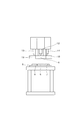
- FIG. 1 It is a side view of an injection molded object. It is a schematic front view of an injection molding apparatus.
- (A)-(C) are operation
- (A)-(C) are operation
- 1 is a hollow injection molded body, and the injection molded body is a first member (for example, polycarbonate resin) 2 and a second member (for example, acrylic resin) made of different materials molded by primary injection. 3, and a resin for integration (resin for integration) 4 is secondarily injected into the butted portion, and a manufacturing apparatus and a manufacturing method for the injection molded body 1 will be described hereinafter. To do.
- first member for example, polycarbonate resin
- a second member for example, acrylic resin
- Reference numeral 5 denotes a turntable.
- the turntable 5 reciprocates between a first position and a second position having an angle of 120 degrees, and the turntable 5 has a lower mold.
- the first, second, and third molds 6, 7, and 8 are disposed at an angle of 120 degrees, but the first and second molds 6 and 7 are for molding the first member 2.
- Female mold the mold on the side where the first member 2 remains when the mold is opened
- the third lower mold 8 is a male mold for molding the second member 3 (the second member when the mold is opened) 3 is the mold on the far side.
- fourth to sixth molds 9, 10 which are upper molds arranged corresponding to the respective stop positions of the first to third molds 6, 7, 8 are provided. 11.
- the fourth to sixth molds 9, 10 and 11 move up and down, and are clamped to the first to third molds 6, 7 and 8 and separated upward and downward to open the mold.
- the first and third injection devices 12, 13, and 14 are provided to perform necessary injections as well as the fourth mold 9 is used for molding the first member 2.
- the male mold, the fifth and sixth molds 10 and 11 are female molds for molding the second member 3.
- the first injection device 12 performs primary injection for forming the first member 2, and the second and third injection devices 13 and 14 supply the primary injection and integration resin 4 for forming the second member 3.
- the secondary injection for injection is performed.
- the manufacturing procedure of the injection molded body will be described with reference to FIGS.
- the turntable is positioned at the first position (see FIG. 4A)
- the first mold 6 faces the fourth mold 9 and the second mold 6 to 11 is in contact with the second mold.
- the third mold 8 is opposed to the sixth mold 11, and the turntable 5 is located at the second position rotated 120 degrees from the first position (FIG. 5 ( In A)
- the first mold 6 faces the sixth mold 11
- the second mold 7 faces the fourth mold 9
- the third mold 8 faces the fifth mold 10. It is arranged.
- the fourth to sixth molds 9, 10, 11 are moved and clamped to the first to third molds 6, 7, 8, respectively, the first, fourth,
- Gokin type 7,10 in the first the secondary injection of the butt portion integrally resin 4 is injected from the second injection unit 13 of the second member 2, a third for molding the second member 3, the sixth Primary injection is performed between the molds 8 and 11 to inject a resin material from the third injection device 14 (first injection step: see FIG. 4A).
- the second injection from the second injection device 13 for integrating the first and second members 2 and 3 is not performed. .
- the fourth to sixth molds 9, 10, and 11 are moved to open the molds with respect to the first to third molds 6, 7, and 8.
- the first member 2 is left in one mold 6, the second member 3 is left in the sixth mold 11, and the integrated injection molded body 1 is molded in the second mold 7 (FIG. 4 (B)), the molded injection-molded body 1 is released using, for example, an ejector pin (not shown) to take out the product.
- the turntable 5 is rotated 120 degrees (clockwise in the present embodiment), and the second and fourth molds 7 and 9, the third and fifth molds 8 and 10, the first and sixth molds. 6 and 11 are opposed to each other (see FIG. 4C).
- the fourth to sixth molds 9, 10, and 11 are clamped to the second, third, and first molds 7, 8, and 6, and the second and seventh molds 7 and 9 are A primary injection for molding the first member 2 from the first injection device 12, a primary injection for molding the second member 3 from the second injection device 13 between the third and fifth molds 8, 10;
- the first and sixth molds 6 and 11 have an integrated resin 4 at the butt portion of the first and second members 2 and 3. the performing the secondary injection to injection from the third injection unit 14 (second injecting step: see FIG. 5 (a)).
- the first member 2 remains in the second mold 7 and the second member 3 remains in the fifth mold 10 and injection.
- the molded body 1 is manufactured and taken out as described above (see FIG. 5B).
- the turntable 5 is reversed 120 degrees (rotated counterclockwise), and the first and fourth molds 6 and 9, the second and fifth molds 7 and 10, the third and sixth molds 8. 11 are opposed to each other (see FIG. 5C), and the fourth to sixth molds 9, 10 and 11 are clamped, the process returns to the first injection step of FIG. Is set to repeat the work.
- the first injection device 12 provided on the fourth mold 9 side performs the primary injection of the first member, and the fifth and the fifth.
- the second and third injection devices 13 and 14 provided on the six molds 10 and 11 side alternately perform the primary injection of the second member 3 and the secondary injection that integrates the first and second members 2 and 3.
- the first member 2 can be opened earlier by opening the fourth mold 9 in the first and second injection steps. If the other member (part such as a valve) 15 is incorporated in the operability, the workability is further improved. However, if the other member 15 is incorporated within the injection molding time of the second member 3, it is wasteful. As a result, the waiting time is eliminated and the workability is further improved.
- the present invention can be used for a manufacturing apparatus and a manufacturing method of an injection molded body such as a side turn lamp.
Landscapes
- Engineering & Computer Science (AREA)
- Manufacturing & Machinery (AREA)
- Mechanical Engineering (AREA)
- Injection Moulding Of Plastics Or The Like (AREA)
- Moulds For Moulding Plastics Or The Like (AREA)
Abstract
課題は、120度の往復回転をするターンテーブル5に120度の角度を存して配した第一~第三金型6、7、8と、これら金型に対向して設けた第四~第六金型9、10、11を用いて射出成形体を連続的に成形するにあたり、第一、第二部材2、3を異材で製造できるようにする事である。 解決手段は、第四~第六金型側に第一~第三射出装置12、13、14を配設し、第一射出装置12からは第一部材2の一次射出をし、第二、第三射出装置13、14からは第二部材3の一次射出と第一、第二部材2、3を一体化するための二次射出をするようにし、これによって第一、第二部材2、3を異材であっても連続的に製造できるようにすることである。
Description
本発明は、サイドターンランプ等の射出成形体の製造装置および製造方法の技術分野に関するものである。
一般に、サイドターンランプ等の中空状の射出成形体は、第一金型、第二金型で第一部材、第二部材を成形(一次の射出成形)をした後、金型をスライド移動して第一、第二部材同士を突き合わせ、二次の射出成形をして両部材同士を一体化するようにしたものが提唱されている(特許文献1参照)。
しかるにこのものは一次射出をした後、二次射出をして一体化を行うというものであるため、製造効率が悪く、コストアップになるという問題がある。
そこで第一金型を回転式とすると共に、第一金型に雄、雄、雌型の型面と、第二金型に雄、雌、雌型の型面とをそれぞれ形成し、第一金型を120度ごとに回転することで、第一、第二部材を成形するための一次射出と第一、第二部材を一体化するための二次射出とを繰り返すようにしたものが知られている(特許文献2参照)。
しかるにこのものは一次射出をした後、二次射出をして一体化を行うというものであるため、製造効率が悪く、コストアップになるという問題がある。
そこで第一金型を回転式とすると共に、第一金型に雄、雄、雌型の型面と、第二金型に雄、雌、雌型の型面とをそれぞれ形成し、第一金型を120度ごとに回転することで、第一、第二部材を成形するための一次射出と第一、第二部材を一体化するための二次射出とを繰り返すようにしたものが知られている(特許文献2参照)。
しかしながら、前記第一金型を回転式にしたものは、第一、第二部材が同じ材料のものであり、このため、第一、第二部材が異材で形成されるサイドターンランプのような射出成形体を連続的に製造することはできないという問題があり、ここに本発明の解決すべき課題がある。
本発明は、上記の如き実情に鑑みこれらの課題を解決することを目的として創作されたものであって、請求項1の発明は、一次射出により成形された第一部材、第二部材を突き合わせた状態で該突き合わせ部に樹脂材を二次射出することで一体化される樹脂成形体を製造するための射出成形体の製造装置であって、該製造装置を、第一位置と第二位置とに120度の往復回転をするターンテーブルと、該ターンテーブルに120度の角度を存して配される第一~第三金型と、該第一~第三金型に対向して設けられ、第一~第三金型に対して型開き、型締め作動をするべく離接する第四~第六金型と、型締めされた各金型内に樹脂を射出するための第一~第三射出装置と、前記ターンテーブルの往復回動、第四~第六金型の離接作動、第一~第三射出装置の射出作動の制御をそれぞれする制御部とを備えて構成するにあたり、第一、第二金型は型開きしたとき射出成形された第一部材が残る雌型、第三金型は型開きしたとき射出成形された第二部材が外れる雄型とし、第四金型は型開きしたとき射出成形された第一部材が外れる雄型、第五、第六金型は型開きしたとき射出成形された第二部材が残る雌型とし、これら金型を、ターンテーブルが第一位置に位置するときには第一金型が第四金型に、第二金型が第五金型に、第三金型が第六金型にそれぞれ対向し、第二位置に位置するときには第一金型が第六金型に、第二金型が第四金型に、第三金型が第五金型に対向するように配設すると共に、前記制御部による射出作動の制御は、ターンテーブルが第一位置に位置するときには、第一、第四金型で第一部材を成形するための第一射出装置による一次射出と、第二、第五金型は一次射出された第一、第二部材を一体化するための第二射出装置による二次射出と、第三金型、第六金型で第二部材を形成するための第三射出装置による一次射出とを行い、ターンテーブルが第二位置に位置するときには、第一、第六金型で一次射出された第一、第二部材を一体化するための第三射出装置による二次射出と、第二、第四金型で第一部材を成形するための第一射出装置による一次射出と、第三、第五金型で第二部材を成形するための第二射出装置による一次射出とをするように設定されていることを特徴とする射出成形体の製造装置である。
請求項2の発明では、第四~第六金型は、各別の型締め、型開き作動をするべく個別に設けられていることを特徴とする請求項1記載の射出成形体の製造装置である。
請求項3の発明は、一次射出により成形された第一部材、第二部材を突き合わせた状態で該突き合わせ部に樹脂材を二次射出することで一体化される樹脂成形体を製造するための射出成形体の製造方法であって、第一位置と第二位置とに120度の往復回転をするターンテーブルと、該ターンテーブルに120度の角度を存して配される第一~第三金型と、該第一~第三金型に対向して設けられ、第一~第三金型に対して型開き、型締め作動をするべく離接する第四~第六金型と、型締めされた各金型内に樹脂を射出するための第一~第三射出装置と、前記ターンテーブルの往復回動、第四~第六金型の離接作動、第一~第三射出装置の射出作動の制御をそれぞれする制御部とを備えて構成するにあたり、第一、第二金型は型開きしたとき射出成形された第一部材が残る雌型、第三金型は型開きしたとき射出成形された第二部材が外れる雄型とし、第四金型は型開きしたとき射出成形された第一部材が外れる雄型、第五、第六金型は型開きしたとき射出成形された第二部材が残る雌型とし、これら金型を、ターンテーブルが第一位置に位置するときには第一金型が第四金型に、第二金型が第五金型に、第三金型が第六金型にそれぞれ対向し、第二位置に位置するときには第一金型が第六金型に、第二金型が第四金型に、第三金型が第五金型に対向するように配設すると共に、前記制御部による射出作動の制御を、ターンテーブルが第一位置に位置する状態で、第一、第四金型で第一部材を成形するための第一射出装置による一次射出と、第二、第五金型は一次射出された第一、第二部材を一体化するための第二射出装置による二次射出と、第三金型、第六金型で第二部材を形成するための第三射出装置による一次射出とを行う第一工程と、ターンテーブルが第二位置に位置する状態で、第一、第六金型で一次射出された第一、第二部材を一体化するための第三射出装置による二次射出と、第二、第四金型で第一部材を成形するための第一射出装置による一次射出と、第三、第五金型で第二部材を成形するための第二射出装置による一次射出とを行う第二工程とを順次繰り返すようにしたことを特徴とする射出成形体の製造方法である。
請求項2の発明では、第四~第六金型は、各別の型締め、型開き作動をするべく個別に設けられていることを特徴とする請求項1記載の射出成形体の製造装置である。
請求項3の発明は、一次射出により成形された第一部材、第二部材を突き合わせた状態で該突き合わせ部に樹脂材を二次射出することで一体化される樹脂成形体を製造するための射出成形体の製造方法であって、第一位置と第二位置とに120度の往復回転をするターンテーブルと、該ターンテーブルに120度の角度を存して配される第一~第三金型と、該第一~第三金型に対向して設けられ、第一~第三金型に対して型開き、型締め作動をするべく離接する第四~第六金型と、型締めされた各金型内に樹脂を射出するための第一~第三射出装置と、前記ターンテーブルの往復回動、第四~第六金型の離接作動、第一~第三射出装置の射出作動の制御をそれぞれする制御部とを備えて構成するにあたり、第一、第二金型は型開きしたとき射出成形された第一部材が残る雌型、第三金型は型開きしたとき射出成形された第二部材が外れる雄型とし、第四金型は型開きしたとき射出成形された第一部材が外れる雄型、第五、第六金型は型開きしたとき射出成形された第二部材が残る雌型とし、これら金型を、ターンテーブルが第一位置に位置するときには第一金型が第四金型に、第二金型が第五金型に、第三金型が第六金型にそれぞれ対向し、第二位置に位置するときには第一金型が第六金型に、第二金型が第四金型に、第三金型が第五金型に対向するように配設すると共に、前記制御部による射出作動の制御を、ターンテーブルが第一位置に位置する状態で、第一、第四金型で第一部材を成形するための第一射出装置による一次射出と、第二、第五金型は一次射出された第一、第二部材を一体化するための第二射出装置による二次射出と、第三金型、第六金型で第二部材を形成するための第三射出装置による一次射出とを行う第一工程と、ターンテーブルが第二位置に位置する状態で、第一、第六金型で一次射出された第一、第二部材を一体化するための第三射出装置による二次射出と、第二、第四金型で第一部材を成形するための第一射出装置による一次射出と、第三、第五金型で第二部材を成形するための第二射出装置による一次射出とを行う第二工程とを順次繰り返すようにしたことを特徴とする射出成形体の製造方法である。
請求項1、3の発明とすることにより、第一、第二部材が異材となる射出成形体を、第一、第二部材を成形するための二つの一次の射出成形と、第一、第二部材を一体化するための二次の射出行程とを、120度の往復回動をするターンテーブルの第一、第二位置において同時にできることになって、製造効率が高く、コストダウンを図ることができる。
請求項2の発明とすることにより、第一、第二部材の射出成形時間が長短異なる場合に、射出成形時間が短い部材について、早期に型開きをして他部材を組込むような作業ができることになって、より製造効率が高いものにできる。
請求項2の発明とすることにより、第一、第二部材の射出成形時間が長短異なる場合に、射出成形時間が短い部材について、早期に型開きをして他部材を組込むような作業ができることになって、より製造効率が高いものにできる。
以下、本発明の実施の形態について、図面に基づいて説明する。図面において、1は中空状の射出成形体であって、該射出成形体は、一次射出で成形された異材からなる第一部材(例えばポリカルボネート樹脂)2と第二部材(例えばアクリル樹脂)3とを突き合わせ、その突き合わせ部に一体化用の樹脂(一体化用樹脂)4を二次射出することで成形されるものであり、以降、該射出成形体1の製造装置および製造方法について説明する。
5はターンテーブルであって、該ターンテーブル5は、120度の角度を存する第一位置と第二位置とに往復回転するようになっているが、ターンテーブル5には、下型となる第一、第二、第三の金型6、7、8が120度の角度を存して配設されているが、第一、第二金型6、7は第一部材2を成形するための雌金型(型開きしたときに第一部材2が残る側の金型)、第三下金型8は第二部材3を成形するための雄金型(型開きしたときに第二部材3が離れる側の金型)となっている。
一方、ターンテーブル5の上方には、前記第一~第三金型6、7、8の各停止位置に対応して配設された上型となる第四~第六金型9、10、11であって、該第四~第六金型9、10、11は上下に移動して前記第一~第三金型6、7、8に対して型締め、型開きするべく上下に離接移動するとともに、それぞれ第一~第三射出装置12、13、14が設けられていて必要な射出をするようになっているが、第四金型9は第一部材2を成形するための雄金型、第五、第六金型10、11は第二部材3を成形するための雌金型になっている。また第一射出装置12は第一部材2を成形するための一次射出をし、第二、第三射出装置13、14は第二部材3を形成するための一次射出と一体化用樹脂4を射出するための二次射出とをするようになっている。
そして前記ターンテーブル5の120度の往復回転の移動制御、第四~第六金型9、10、11の型締め、型開きの離接制御、第一~第三射出装置12、13、14の射出制御は、図示しない制御部からの指令で実行されるようになっている。
次に、射出成形体の製造手順について図4、5を用いて説明する。まず前記各金型6~11同士は、ターンテーブルが第一位置に位置するとき(図4(A)参照)には、第一金型6が第四金型9に対向し、第二金型7が第五金型10に対向し、第三金型8が第六金型11に対向し、ターンテーブル5が前記第一位置から120度回転した第二位置に位置するとき(図5(A)参照)には第一金型6が第六金型11に対向し、第二金型7が第四金型9に対向し、第三金型8が第五金型10に対向するように配設されている。
そして第四~第六金型9、10、11が移動して第一~第三金型6、7、8にそれぞれ型締めされると、第一部材2を成形するため第一、第四金型6、9のあいだに第一射出装置12からの樹脂材の一次射出と、後述する第二射出工程で成形された第一、第二部材2、3を一体化するため第二、第五金型7、10において第一、第二部材2、3の突合せ部位に一体化樹脂4を第二射出装置13から射出する二次射出と、第二部材3を成形するため第三、第六金型8、11のあいだに第三射出装置14から樹脂材を射出する一次射出とが行われる(第一射出工程:図4(A)参照)。尚、第一、第二部材2、3が成形されていない最初の工程では、第一、第二部材2、3を一体化するための第二射出装置13からの第二射出は行われない。
そして第四~第六金型9、10、11が移動して第一~第三金型6、7、8にそれぞれ型締めされると、第一部材2を成形するため第一、第四金型6、9のあいだに第一射出装置12からの樹脂材の一次射出と、後述する第二射出工程で成形された第一、第二部材2、3を一体化するため第二、第五金型7、10において第一、第二部材2、3の突合せ部位に一体化樹脂4を第二射出装置13から射出する二次射出と、第二部材3を成形するため第三、第六金型8、11のあいだに第三射出装置14から樹脂材を射出する一次射出とが行われる(第一射出工程:図4(A)参照)。尚、第一、第二部材2、3が成形されていない最初の工程では、第一、第二部材2、3を一体化するための第二射出装置13からの第二射出は行われない。
前記第一射出行程が終了すると、第四~第六金型9、10、11が移動して第一~第三金型6、7、8に対して型開きをするが、このとき、第一金型6には第一部材2が残され、第六金型11には第二部材3が残され、第二金型7には、一体化された射出成形体1が成形され(図4(B)参照)、該成形された射出成形体1を図示しないエジェクターピンを用いる等して離型させて製品取出しをする。
次にターンテーブル5を120度回転(本実施の形態では時計回り)させて第二、第四金型7、9同士、第三、第五金型8、10同士、第一、第六金型6、11同士をそれぞれ対向させる(図4(C)参照)。
しかる後、第四~第六金型9、10、11を第二、第三、第一金型7、8、6に型締めし、第二、第七金型7、9のあいだに第一射出装置12から第一部材2を成形するための一次射出と、第三、第五金型8、10のあいだに第二射出装置13から第二部材3を成形するための一次射出と、前記第一射出工程において成形された第一、第二部材2、3を一体化するため第一、第六金型6、11において第一、第二部材2、3の突合せ部位に一体化樹脂4を第三射出装置14から射出する二次射出とを行う(第二射出行程:図5(A)参照)。
次いで、第四~第六金型9、10、11を離間移動して型開きすると、第一部材2は第二金型7に残り、第二部材3は第五金型10に残ると共に、射出成形体1が製造され、これを前記したように取り出す(図5(B)参照)。
その後、ターンテーブル5を120度反転(反時計回りに回転)させて、第一、第四金型6、9同士、第二、第五金型7、10同士、第三、第六金型8、11同士を対向させ(図5(C)参照)、第四~第六金型9、10、11を型締めすると、前記図4(A)の第一射出工程に戻り、以下、この順序で作業が繰り返されるように設定されている。
叙述の如く構成された本実施の形態において、第一部材2、第二部材3の一次射出による成形と、成形された第一、第二部材2、3を一体化するための二次射出による成形とが同時連続的に行われることになるものでありながら、この場合において、第四金型9側に設けられた第一射出装置12が第一部材の一次射出をし、第五、第六金型10、11側に設けられた第二、第三射出装置13、14が交互に第二部材3の一次射出と第一、第二部材2、3を一体化する二次射出とを行うことになり、この結果、第一、第二部材2、3が異材であっても射出成形体1の一連の製造ができることになって生産効率が向上する。
この場合において、第一部材2の射出成形時間が第二部材3の射出成形時間より短い場合、第一、第二射出工程において第四金型9の型開き作動を早くして第一部材2に他部材(バルブ等の部品)15を組込むようにすれば、作業性がさらに向上するが、この他部材15の組込みを、第二部材3の射出成形時間内に行うようにすれば、無駄な待機時間が無くなることになってより一層の作業性の向上が図られる。
本発明は、サイドターンランプ等の射出成形体の製造装置および製造方法に利用することができる。
1 射出成形体
2 第一部材
3 第二部材
4 一体化樹脂
5 ターンテーブル
6 第一金型
7 第二金型
8 第三金型
9 第四金型
10 第五金型
11 第六金型
12 第一射出装置
13 第二射出装置
14 第三射出装置
2 第一部材
3 第二部材
4 一体化樹脂
5 ターンテーブル
6 第一金型
7 第二金型
8 第三金型
9 第四金型
10 第五金型
11 第六金型
12 第一射出装置
13 第二射出装置
14 第三射出装置
Claims (3)
- 一次射出により成形された第一部材、第二部材を突き合わせた状態で該突き合わせ部に樹脂材を二次射出することで一体化される樹脂成形体を製造するための射出成形体の製造装置であって、該製造装置を、第一位置と第二位置とに120度の往復回転をするターンテーブルと、該ターンテーブルに120度の角度を存して配される第一~第三金型と、該第一~第三金型に対向して設けられ、第一~第三金型に対して型開き、型締め作動をするべく離接する第四~第六金型と、型締めされた各金型内に樹脂を射出するための第一~第三射出装置と、前記ターンテーブルの往復回動、第四~第六金型の離接作動、第一~第三射出装置の射出作動の制御をそれぞれする制御部とを備えて構成するにあたり、第一、第二金型は型開きしたとき射出成形された第一部材が残る雌型、第三金型は型開きしたとき射出成形された第二部材が外れる雄型とし、第四金型は型開きしたとき射出成形された第一部材が外れる雄型、第五、第六金型は型開きしたとき射出成形された第二部材が残る雌型とし、これら金型を、ターンテーブルが第一位置に位置するときには第一金型が第四金型に、第二金型が第五金型に、第三金型が第六金型にそれぞれ対向し、第二位置に位置するときには第一金型が第六金型に、第二金型が第四金型に、第三金型が第五金型に対向するように配設すると共に、前記制御部による射出作動の制御は、ターンテーブルが第一位置に位置するときには、第一、第四金型で第一部材を成形するための第一射出装置による一次射出と、第二、第五金型は一次射出された第一、第二部材を一体化するための第二射出装置による二次射出と、第三金型、第六金型で第二部材を形成するための第三射出装置による一次射出とを行い、ターンテーブルが第二位置に位置するときには、第一、第六金型で一次射出された第一、第二部材を一体化するための第三射出装置による二次射出と、第二、第四金型で第一部材を成形するための第一射出装置による一次射出と、第三、第五金型で第二部材を成形するための第二射出装置による一次射出とをするように設定されていることを特徴とする射出成形体の製造装置。
- 第四~第六金型は、各別の型締め、型開き作動をするべく個別に設けられていることを特徴とする請求項1記載の射出成形体の製造装置。
- 一次射出により成形された第一部材、第二部材を突き合わせた状態で該突き合わせ部に樹脂材を二次射出することで一体化される樹脂成形体を製造するための射出成形体の製造方法であって、第一位置と第二位置とに120度の往復回転をするターンテーブルと、該ターンテーブルに120度の角度を存して配される第一~第三金型と、該第一~第三金型に対向して設けられ、第一~第三金型に対して型開き、型締め作動をするべく離接する第四~第六金型と、型締めされた各金型内に樹脂を射出するための第一~第三射出装置と、前記ターンテーブルの往復回動、第四~第六金型の離接作動、第一~第三射出装置の射出作動の制御をそれぞれする制御部とを備えて構成するにあたり、第一、第二金型は型開きしたとき射出成形された第一部材が残る雌型、第三金型は型開きしたとき射出成形された第二部材が外れる雄型とし、第四金型は型開きしたとき射出成形された第一部材が外れる雄型、第五、第六金型は型開きしたとき射出成形された第二部材が残る雌型とし、これら金型を、ターンテーブルが第一位置に位置するときには第一金型が第四金型に、第二金型が第五金型に、第三金型が第六金型にそれぞれ対向し、第二位置に位置するときには第一金型が第六金型に、第二金型が第四金型に、第三金型が第五金型に対向するように配設すると共に、前記制御部による射出作動の制御を、ターンテーブルが第一位置に位置する状態で、第一、第四金型で第一部材を成形するための第一射出装置による一次射出と、第二、第五金型は一次射出された第一、第二部材を一体化するための第二射出装置による二次射出と、第三金型、第六金型で第二部材を形成するための第三射出装置による一次射出とを行う第一工程と、ターンテーブルが第二位置に位置する状態で、第一、第六金型で一次射出された第一、第二部材を一体化するための第三射出装置による二次射出と、第二、第四金型で第一部材を成形するための第一射出装置による一次射出と、第三、第五金型で第二部材を成形するための第二射出装置による一次射出とを行う第二工程とを順次繰り返すようにしたことを特徴とする射出成形体の製造方法。
Priority Applications (2)
| Application Number | Priority Date | Filing Date | Title |
|---|---|---|---|
| US15/535,706 US10562213B2 (en) | 2014-12-22 | 2015-12-03 | Device for producing injection molded body and method of producing the same |
| CN201580068345.3A CN107107412A (zh) | 2014-12-22 | 2015-12-03 | 注射成型体的制造装置及制造方法 |
Applications Claiming Priority (2)
| Application Number | Priority Date | Filing Date | Title |
|---|---|---|---|
| JP2014258589A JP6372960B2 (ja) | 2014-12-22 | 2014-12-22 | 射出成形体の製造装置および製造方法 |
| JP2014-258589 | 2014-12-22 |
Publications (1)
| Publication Number | Publication Date |
|---|---|
| WO2016104090A1 true WO2016104090A1 (ja) | 2016-06-30 |
Family
ID=56150121
Family Applications (1)
| Application Number | Title | Priority Date | Filing Date |
|---|---|---|---|
| PCT/JP2015/083955 Ceased WO2016104090A1 (ja) | 2014-12-22 | 2015-12-03 | 射出成形体の製造装置および製造方法 |
Country Status (4)
| Country | Link |
|---|---|
| US (1) | US10562213B2 (ja) |
| JP (1) | JP6372960B2 (ja) |
| CN (1) | CN107107412A (ja) |
| WO (1) | WO2016104090A1 (ja) |
Cited By (2)
| Publication number | Priority date | Publication date | Assignee | Title |
|---|---|---|---|---|
| JP2021084380A (ja) * | 2019-11-29 | 2021-06-03 | 株式会社ミツバ | 射出成形装置 |
| CN112969562A (zh) * | 2018-11-14 | 2021-06-15 | 株式会社美姿把 | 射出成形体的制造装置以及制造方法、树脂成形品 |
Families Citing this family (13)
| Publication number | Priority date | Publication date | Assignee | Title |
|---|---|---|---|---|
| JP6451603B2 (ja) * | 2015-11-18 | 2019-01-16 | 株式会社デンソー | 中空品の製造方法 |
| JP7105178B2 (ja) * | 2018-11-14 | 2022-07-22 | 株式会社ミツバ | 射出成形体の製造装置および製造方法 |
| JP7142583B2 (ja) * | 2019-01-30 | 2022-09-27 | 株式会社ミツバ | 射出成形体の製造装置および製造方法 |
| JP2020121457A (ja) * | 2019-01-30 | 2020-08-13 | 株式会社ミツバ | 射出成形体の製造装置および製造方法、インサート成形品 |
| CN109693335A (zh) * | 2019-02-26 | 2019-04-30 | 华域视觉科技(上海)有限公司 | 一种可实现双工件模内装配的连续注塑设备及实现方法 |
| JP7254685B2 (ja) * | 2019-11-29 | 2023-04-10 | 株式会社ミツバ | 射出成形装置 |
| JP7303758B2 (ja) * | 2020-01-20 | 2023-07-05 | 株式会社ミツバ | 射出成形体の製造方法 |
| US12049032B2 (en) | 2020-03-20 | 2024-07-30 | King Steel Machinery Co., Ltd. | Injection molding method |
| US11780129B2 (en) | 2020-03-20 | 2023-10-10 | King Steel Machinery Co., Ltd. | Molding method for operating molding device |
| JP7383556B2 (ja) * | 2020-04-10 | 2023-11-20 | 株式会社ミツバ | 樹脂製ケースの製造方法 |
| JP7396658B2 (ja) * | 2020-04-13 | 2023-12-12 | 株式会社ミツバ | モータの製造方法 |
| JP7431397B2 (ja) * | 2020-04-17 | 2024-02-15 | 株式会社ミツバ | 樹脂製ギヤの製造方法及び樹脂製ギヤ |
| JP7403183B2 (ja) * | 2022-04-07 | 2023-12-22 | キング スチール マシネリー カンパニー リミテッド | 高分子部材の組立品及び射出成型方法 |
Citations (5)
| Publication number | Priority date | Publication date | Assignee | Title |
|---|---|---|---|---|
| JPH06182806A (ja) * | 1992-12-18 | 1994-07-05 | Ube Jushi Kako Kk | 中空成形品の成形方法及び成形金型 |
| JP2000071282A (ja) * | 1998-09-01 | 2000-03-07 | Daikyo Inc | 合成樹脂製管状体の成形装置およびそれを用いた製造方法 |
| JP2000218661A (ja) * | 1999-01-29 | 2000-08-08 | Dekku Kk | 回転射出成形用成形装置 |
| JP2009023248A (ja) * | 2007-07-20 | 2009-02-05 | Oshima Denki Seisakusho:Kk | 射出成形体の製造装置、燈体の製造装置、燈体の製造方法および燈体 |
| JP2011083959A (ja) * | 2009-10-15 | 2011-04-28 | Ube Machinery Corporation Ltd | 中空体製品の成型用金型及び成型方法 |
Family Cites Families (7)
| Publication number | Priority date | Publication date | Assignee | Title |
|---|---|---|---|---|
| JPS58193125A (ja) * | 1982-05-06 | 1983-11-10 | Tokan Kogyo Co Ltd | 多層容器の製造方法 |
| DE3820459C1 (ja) | 1988-06-16 | 1989-11-09 | Kernforschungsanlage Juelich Gmbh, 5170 Juelich, De | |
| JPH0751294B2 (ja) * | 1988-12-14 | 1995-06-05 | 株式会社名機製作所 | 多色成形用堅型ロータリー射出成形機 |
| US5221538A (en) * | 1990-08-06 | 1993-06-22 | Japan Steel Works, Ltd. | Rotational injection molding machine having a plurality of combinations of male and female dies |
| US5413743A (en) * | 1993-05-20 | 1995-05-09 | General Motors Corporation | Method of making a lamp assembly |
| JPH084830A (ja) | 1994-06-23 | 1996-01-12 | Showa Electric Wire & Cable Co Ltd | 除振台位置制御方法 |
| US7951322B2 (en) * | 2006-06-13 | 2011-05-31 | Electroform Company | Method and apparatus for molding and assembling plural-part plastic assemblies |
-
2014
- 2014-12-22 JP JP2014258589A patent/JP6372960B2/ja active Active
-
2015
- 2015-12-03 WO PCT/JP2015/083955 patent/WO2016104090A1/ja not_active Ceased
- 2015-12-03 CN CN201580068345.3A patent/CN107107412A/zh active Pending
- 2015-12-03 US US15/535,706 patent/US10562213B2/en active Active
Patent Citations (5)
| Publication number | Priority date | Publication date | Assignee | Title |
|---|---|---|---|---|
| JPH06182806A (ja) * | 1992-12-18 | 1994-07-05 | Ube Jushi Kako Kk | 中空成形品の成形方法及び成形金型 |
| JP2000071282A (ja) * | 1998-09-01 | 2000-03-07 | Daikyo Inc | 合成樹脂製管状体の成形装置およびそれを用いた製造方法 |
| JP2000218661A (ja) * | 1999-01-29 | 2000-08-08 | Dekku Kk | 回転射出成形用成形装置 |
| JP2009023248A (ja) * | 2007-07-20 | 2009-02-05 | Oshima Denki Seisakusho:Kk | 射出成形体の製造装置、燈体の製造装置、燈体の製造方法および燈体 |
| JP2011083959A (ja) * | 2009-10-15 | 2011-04-28 | Ube Machinery Corporation Ltd | 中空体製品の成型用金型及び成型方法 |
Cited By (6)
| Publication number | Priority date | Publication date | Assignee | Title |
|---|---|---|---|---|
| CN112969562A (zh) * | 2018-11-14 | 2021-06-15 | 株式会社美姿把 | 射出成形体的制造装置以及制造方法、树脂成形品 |
| US20210394408A1 (en) * | 2018-11-14 | 2021-12-23 | Mitsuba Corporation | Apparatus and method for manufacturing injection molded article, and resin molded article |
| CN112969562B (zh) * | 2018-11-14 | 2023-06-23 | 株式会社美姿把 | 射出成形体的制造装置以及制造方法、树脂成形品 |
| JP2021084380A (ja) * | 2019-11-29 | 2021-06-03 | 株式会社ミツバ | 射出成形装置 |
| WO2021106815A1 (ja) * | 2019-11-29 | 2021-06-03 | 株式会社ミツバ | 射出成形装置 |
| JP7213171B2 (ja) | 2019-11-29 | 2023-01-26 | 株式会社ミツバ | 射出成形装置 |
Also Published As
| Publication number | Publication date |
|---|---|
| US20170348883A1 (en) | 2017-12-07 |
| JP6372960B2 (ja) | 2018-08-15 |
| CN107107412A (zh) | 2017-08-29 |
| JP2016117221A (ja) | 2016-06-30 |
| US10562213B2 (en) | 2020-02-18 |
Similar Documents
| Publication | Publication Date | Title |
|---|---|---|
| JP6372960B2 (ja) | 射出成形体の製造装置および製造方法 | |
| CN104369317B (zh) | 一种透明件与非透明件组合成型的双色模具 | |
| US10363692B2 (en) | Method for manufacturing liquid supply member | |
| WO2018232590A1 (zh) | 一种管状产品的一次注塑成型模具及其成型方法 | |
| JP5300513B2 (ja) | 射出成形体の製造方法および射出成形体の製造装置 | |
| CN102773970B (zh) | 离合器式滑块机构 | |
| US9718227B2 (en) | Device and method for producing injection-molded parts which comprise different components | |
| WO2013034604A3 (en) | A moulding arrangement and a method for producing an article using the moulding arrangement | |
| CN203792666U (zh) | 开合模机构及双分型面注塑模具 | |
| AU2018358705A1 (en) | Injection mold and method for producing a double walled drinking vessel, the double walled drinking vessel comprising an outer container and an inner container | |
| US10335988B2 (en) | Injection mold with a transfer loader and associated injection method | |
| CN104149290A (zh) | 具有油缸抽芯结构的注塑模具 | |
| CN106564167A (zh) | 一种单直pin针插件母座轴向侧抽芯嵌件注塑模结构 | |
| KR200440564Y1 (ko) | 언더컷 성형을 위한 슬라이드 코아장치 | |
| JP6431763B2 (ja) | 射出成形体の製造装置および製造方法 | |
| CN104149280B (zh) | 剪刀脚成型组装一体模具 | |
| CN203973952U (zh) | 空滤泵壳模具 | |
| CN103963250A (zh) | 双色模二射模具合模控制结构 | |
| CN107662310B (zh) | 接续成型的模制加工方法 | |
| CN107599710B (zh) | 一种纽扣的雕刻方法 | |
| WO2017017544A1 (en) | Plant for the production of ceramic sanitary wares, as well as related method | |
| CN105014880A (zh) | 一种厚壁实心注塑产品成型模具 | |
| JP7179882B2 (ja) | 金型、物品の製造方法、画像形成装置の製造方法、制御プログラム、記録媒体 | |
| CN104191562B (zh) | 空滤泵壳模具 | |
| CN102632588A (zh) | 公模切换机构 |
Legal Events
| Date | Code | Title | Description |
|---|---|---|---|
| 121 | Ep: the epo has been informed by wipo that ep was designated in this application |
Ref document number: 15872659 Country of ref document: EP Kind code of ref document: A1 |
|
| WWE | Wipo information: entry into national phase |
Ref document number: 15535706 Country of ref document: US |
|
| NENP | Non-entry into the national phase |
Ref country code: DE |
|
| 122 | Ep: pct application non-entry in european phase |
Ref document number: 15872659 Country of ref document: EP Kind code of ref document: A1 |