WO2016104030A1 - 移動体制御装置、移動体制御方法、および移動体制御プログラム - Google Patents
移動体制御装置、移動体制御方法、および移動体制御プログラム Download PDFInfo
- Publication number
- WO2016104030A1 WO2016104030A1 PCT/JP2015/083151 JP2015083151W WO2016104030A1 WO 2016104030 A1 WO2016104030 A1 WO 2016104030A1 JP 2015083151 W JP2015083151 W JP 2015083151W WO 2016104030 A1 WO2016104030 A1 WO 2016104030A1
- Authority
- WO
- WIPO (PCT)
- Prior art keywords
- moving body
- fixed point
- point position
- disturbance
- moving
- Prior art date
- Legal status (The legal status is an assumption and is not a legal conclusion. Google has not performed a legal analysis and makes no representation as to the accuracy of the status listed.)
- Ceased
Links
Images




Classifications
-
- B—PERFORMING OPERATIONS; TRANSPORTING
- B63—SHIPS OR OTHER WATERBORNE VESSELS; RELATED EQUIPMENT
- B63H—MARINE PROPULSION OR STEERING
- B63H25/00—Steering; Slowing-down otherwise than by use of propulsive elements; Dynamic anchoring, i.e. positioning vessels by means of main or auxiliary propulsive elements
- B63H25/46—Steering or dynamic anchoring by jets or by rudders carrying jets
-
- B—PERFORMING OPERATIONS; TRANSPORTING
- B63—SHIPS OR OTHER WATERBORNE VESSELS; RELATED EQUIPMENT
- B63H—MARINE PROPULSION OR STEERING
- B63H25/00—Steering; Slowing-down otherwise than by use of propulsive elements; Dynamic anchoring, i.e. positioning vessels by means of main or auxiliary propulsive elements
- B63H25/02—Initiating means for steering, for slowing down, otherwise than by use of propulsive elements, or for dynamic anchoring
- B63H25/04—Initiating means for steering, for slowing down, otherwise than by use of propulsive elements, or for dynamic anchoring automatic, e.g. reacting to compass
-
- B—PERFORMING OPERATIONS; TRANSPORTING
- B63—SHIPS OR OTHER WATERBORNE VESSELS; RELATED EQUIPMENT
- B63H—MARINE PROPULSION OR STEERING
- B63H25/00—Steering; Slowing-down otherwise than by use of propulsive elements; Dynamic anchoring, i.e. positioning vessels by means of main or auxiliary propulsive elements
- B63H25/06—Steering by rudders
-
- B—PERFORMING OPERATIONS; TRANSPORTING
- B63—SHIPS OR OTHER WATERBORNE VESSELS; RELATED EQUIPMENT
- B63H—MARINE PROPULSION OR STEERING
- B63H25/00—Steering; Slowing-down otherwise than by use of propulsive elements; Dynamic anchoring, i.e. positioning vessels by means of main or auxiliary propulsive elements
- B63H25/06—Steering by rudders
- B63H25/38—Rudders
-
- B—PERFORMING OPERATIONS; TRANSPORTING
- B63—SHIPS OR OTHER WATERBORNE VESSELS; RELATED EQUIPMENT
- B63H—MARINE PROPULSION OR STEERING
- B63H25/00—Steering; Slowing-down otherwise than by use of propulsive elements; Dynamic anchoring, i.e. positioning vessels by means of main or auxiliary propulsive elements
- B63H25/42—Steering or dynamic anchoring by propulsive elements; Steering or dynamic anchoring by propellers used therefor only; Steering or dynamic anchoring by rudders carrying propellers
-
- B—PERFORMING OPERATIONS; TRANSPORTING
- B63—SHIPS OR OTHER WATERBORNE VESSELS; RELATED EQUIPMENT
- B63H—MARINE PROPULSION OR STEERING
- B63H25/00—Steering; Slowing-down otherwise than by use of propulsive elements; Dynamic anchoring, i.e. positioning vessels by means of main or auxiliary propulsive elements
- B63H25/02—Initiating means for steering, for slowing down, otherwise than by use of propulsive elements, or for dynamic anchoring
- B63H25/04—Initiating means for steering, for slowing down, otherwise than by use of propulsive elements, or for dynamic anchoring automatic, e.g. reacting to compass
- B63H2025/045—Initiating means for steering, for slowing down, otherwise than by use of propulsive elements, or for dynamic anchoring automatic, e.g. reacting to compass making use of satellite radio beacon positioning systems, e.g. the Global Positioning System [GPS]
-
- B—PERFORMING OPERATIONS; TRANSPORTING
- B63—SHIPS OR OTHER WATERBORNE VESSELS; RELATED EQUIPMENT
- B63H—MARINE PROPULSION OR STEERING
- B63H25/00—Steering; Slowing-down otherwise than by use of propulsive elements; Dynamic anchoring, i.e. positioning vessels by means of main or auxiliary propulsive elements
- B63H25/46—Steering or dynamic anchoring by jets or by rudders carrying jets
- B63H2025/465—Jets or thrusters substantially used for steering or dynamic anchoring only, with means for retracting, or otherwise moving to a rest position outside the water flow around the hull
Definitions
- the present invention relates to a moving body control device, a moving body control method, and a moving body control program for moving a moving body.
- a ship attaches a spanker to direct the bow in the wind direction (refer to Patent Document 1), or moves to a desired direction (for example, to the starboard side of the hull). It is necessary to attach a thruster (see Patent Document 2).
- a 1-axis 1-steered ship with one rudder and only one propulsive force cannot move in a direction orthogonal to the bow-stern direction.
- the moving body control device of the present invention comprises a propulsive force generating section for propelling the moving body in a specific direction, and a moving direction adjusting section for adjusting the direction of movement by the propulsive force.
- a disturbance direction estimating means for estimating a direction of disturbance for moving the moving body, a moving body direction detecting means for detecting a direction in which the moving body is directed, a position detecting means for detecting the position of the moving body, and the moving body
- a position setting means for setting a fixed point position, which is a position to be stopped, and a direction in which the moving body detected by the moving body direction detecting means faces the direction of the disturbance estimated by the disturbance direction estimating means, and the position Control means for controlling the propulsive force generating section and the moving direction adjusting section so that the moving body stays at the fixed point position set by the setting means; and changing means for sequentially changing the fixed point position.
- the control means controls the propulsive force generation unit and the moving body direction adjusting unit so that the moving body is not caused to flow by disturbance, so that the moving body stays at the fixed point position.
- the control means moves the moving body to the changed fixed point position each time. Therefore, the mobile body control device of the present invention can sequentially move the mobile body in the direction of the disturbance.
- the changing means may change the fixed point position when the distance between the position of the moving body detected by the position detecting means and the fixed point position is less than a first predetermined distance.
- the moving body control device moves the moving body continuously in order to change the fixed point position when the moving body approaches the fixed point position to the first predetermined distance.
- the moving body control device includes speed detecting means for detecting a moving speed of the moving body, and the changing means changes the fixed point position when the speed detected by the speed detecting means is less than a predetermined speed. It is good also as an aspect to do.
- the moving body control device performs control to keep the moving body at the fixed point position, the speed of the moving body decreases as the moving body approaches the fixed point position. Therefore, the mobile body control device determines that the mobile body has approached the fixed point position when the speed of the mobile body becomes less than the predetermined speed, and changes the fixed point position. Then, the moving body continuously moves as the fixed point position is changed.
- the changing means can change the fixed point position every predetermined time.
- the changing unit may receive a target route on which the moving body should move and change the fixed point position on the target route.
- the moving body control device changes the fixed point position along the received target route, it can move the moving body along the target route.
- the disturbance is a wind and a tidal current that moves the moving body
- the control unit performs the propulsion so that the direction of the moving body detected by the moving body direction detecting unit faces the wind direction. You may control a force generation part and the said movement direction adjustment part.
- the moving body control device can make the moving body face the wind direction even if the moving body does not include a spanker.
- the control unit may control the propulsive force generating unit and the moving direction adjusting unit so that the direction in which the moving body is detected detected by the moving body direction detecting unit faces the tidal current direction.
- the control means receives a target that is a target of movement of the moving body, and controls the direction of the moving body detected by the moving body direction detecting means according to the direction of the target.
- the control means controls the direction in which the moving body is facing according to the direction of the target (for example, quay or pier).
- the control means can control the moving body so that the direction in which the moving body is facing is the direction in which the target is present.
- the changing means may change the fixed point position to a position that is located in a direction orthogonal to the direction in which the target is present and that is at a second predetermined distance from the target. .
- the fixed point position is changed to a position that is parallel to the direction of the quay and is, for example, 10 m away from the quay. Therefore, the mobile body control device can move the mobile body in parallel to the quay direction while keeping the mobile body perpendicular to the quay direction.
- control means can also control the direction in which the moving body is directed so as to be orthogonal to the direction in which the target is present.
- the changing means may change the fixed point position to a position located in a direction in which the target is present and a distance from the target is a third predetermined distance.
- the fixed point position is changed to a position where the pier exists and is 2 m away from the pier, for example. Therefore, the moving body control device can move the moving body to a fixed point position close to the pier while facing the direction in which the pier exists.
- the control means stops the control that stays (goes to) at the fixed point position, and performs only the control that makes the direction in which the moving body faces the direction of the disturbance.
- the moving body control device prevents the moving body from moving along a useless route.
- the present invention is not limited to the device, and may be a moving body control method for controlling a moving body or a moving body control program executed by a moving body control device.
- the moving body can be moved along the fixed point position that is sequentially changed while the moving body is directed in a predetermined direction without the need for additional equipment capable of moving in the right and left directions.
- FIG. 1 is a block diagram showing the main configuration of a ship 10 according to an embodiment of the present invention.
- the ship 10 includes a hull control device 20, a power source 30, a propeller 31, and a rudder 40.
- the hull control device 20 includes an antenna 21, a positioning unit 22, a sensor 23, a hull control unit 24, an operation unit 25, a power control unit 26, and a rudder control unit 27.
- the hull control unit 24 includes a disturbance direction estimation unit 240 and a fixed point setting unit 241.
- the positioning unit 22 corresponds to the “position detecting means” of the present invention.
- the hull control unit 24 corresponds to “position setting means”, “control means”, and “change means” of the present invention.
- a set of the power source 30 and the propeller 31 corresponds to a “propulsion generation unit”.
- the rudder 40 corresponds to a “moving direction adjusting unit”.
- the ship 10 is a 1-axis 1-steer ship that has one rudder (the rudder 40) and can only move forward or backward.
- the antenna 21 receives a GPS (; Global Positioning System) positioning signal and outputs it to the positioning unit 22.
- the positioning unit 22 performs a positioning calculation using the GPS positioning signal and calculates the position of the ship 10. This positioning calculation is executed at every positioning timing set in advance.
- the positioning unit 22 outputs the calculated position of the ship 10 to the hull control unit 24.
- the sensor 23 is, for example, a necessary one of a heading sensor for detecting the heading (corresponding to the moving body direction detecting means of the present invention), a speed sensor for detecting the ship speed, a wind direction sensor, a wind speed sensor, a tide meter, and the like. Consists of The sensor 23 outputs the detected heading, speed, wind direction, wind speed, and tidal current to the hull control unit 24 as necessary.
- the sensor 23 may be attached as necessary, and is not an essential configuration of the present invention. For example, when the sensor 23 is not provided with a heading sensor or a speed sensor, the hull control unit 24 can estimate the heading or the speed of the ship 10 from the change in the current position.
- the operation unit 25 is a so-called user interface device, and receives an operation input by the user and outputs it to the hull control unit 24.
- the fixed point setting unit 241 sets a fixed point input from the user via the operation unit 25.
- the disturbance azimuth estimating unit 240 estimates the azimuth of the disturbance that moves the ship 10.
- Disturbance mainly consists of tidal current and wind.
- the hull control unit 24 sets control information for controlling the ship 10 so as to remain at a fixed position.
- the control information includes, for example, power amount information and propulsion direction information.
- Information on the amount of power is output to the power control unit 26.
- Information on the propulsion direction is output to the rudder control unit 27.
- the power control unit 26 drives and controls the power source 30 based on the information on the amount of power.
- the power source 30 is composed of a diesel engine or a motor.
- the power source 30 gives the propeller 31 the power generated based on the control of the power control unit 26.
- the power source 30 may be a hybrid mechanism including both a diesel engine and a motor.
- the rudder control unit 27 adjusts the rudder angle of the rudder 40 with respect to the heading of the ship 10.
- the rudder control unit 27 adjusts the rudder angle of the rudder 40 based on the propulsion direction information output from the hull control unit 24.
- the ship 10 moves toward the fixed point position by controlling the propulsion force of the propeller 31 and the rudder angle of the rudder 40.
- the ship 10 estimates a disturbance azimuth that is a disturbance azimuth for moving the ship 10, controls the amount of power and the propulsion direction based on the estimated disturbance azimuth, and moves toward a fixed point.
- FIG. 2 is a diagram illustrating an example of estimating the disturbance direction.
- the fixed point setting unit 241 determines and sets the fixed point position designated by the user via the operation unit 25 as the fixed point position Pp.
- the disturbance direction estimation unit 240 estimates the disturbance direction.
- the disturbance direction as the initial value may be any direction, for example, a true south direction.
- the hull control unit 24 controls the propulsion direction so that the bow direction faces the estimated disturbance direction.
- the disturbance azimuth estimation unit 240 obtains a distance XTE (; Cross Track Error) between the current position Ps and a disturbance opposing line that passes through the fixed point position Pp and is parallel to the estimated disturbance azimuth. .
- XTE Cross Track Error
- the distance XTE becomes 0 when the estimated disturbance azimuth coincides with the bow azimuth and the ship 10 heads to the fixed point position Pp.
- the disturbance azimuth estimation unit 240 obtains the distance XTE every predetermined time, and, as shown in the following formula 1, the difference between the estimated disturbance azimuth and the correction value based on the distance XTE is used to create a new disturbance. Calculate the bearing.
- the disturbance azimuth estimation unit 240 sets the distance XTE to 0 based on the proportional component of the distance XTE (the term of the proportional correction gain in Formula 1) and the integral component of the distance XTE (the term of ⁇ in Formula 1). Update the estimated disturbance direction.
- the disturbance azimuth estimating unit 240 includes convergence (distance XTE is 0) by including a differential term of the distance XTE (term of the second integral correction gain of Equation 1) in the integral component of the distance XTE (term of ⁇ in Equation 1).
- the estimated disturbance azimuth can be brought close to the actual disturbance azimuth smoothly until convergence.
- FIG. 3 is a diagram illustrating an example in which the amount of power is controlled in a situation where the ship 10 is subjected to disturbance and the vehicle 10 remains at the fixed point position Pp.
- the disturbance vector Ddr is a velocity vector composed of the direction and magnitude of the disturbance.
- Zone U is an area upstream of the disturbance from the disturbance orthogonal line passing through the fixed point position Pp and orthogonal to the disturbance direction.
- ZoneD is an area on the downstream side of the disturbance from the disturbance orthogonal line.
- Ship 10 ' shows the ship 10 when it is located in ZoneU.
- Ship 10 '' shows ship 10 when it is located in ZoneD.
- the hull control unit 24 controls the amount of power to move forward or backward based on the direction, bow direction, and fixed point position of the disturbance vector Ddr.
- the heading when the angle between the heading with respect to the center of the hull and the direction of the disturbance vector Ddr is in the range of ⁇ 90 degrees or more and less than +90 degrees, the heading is the direction of the disturbance vector Ddr. It is referred to as facing.
- the angle between the heading and the direction of the disturbance vector Ddr is an angle outside the range of ⁇ 90 degrees or more and less than +90 degrees, the heading is referred to as non-opposing to the direction of the disturbance vector Ddr.
- the hull control unit 24 outputs power amount control information so as to move backward when the heading of the ship 10 ′ faces the direction of the disturbance vector Ddr and exists in ZoneU. As shown in FIG. 3, the hull control unit 24 outputs power amount control information so as to move forward when the heading of the ship 10 ′′ faces the direction of the disturbance vector Ddr and exists in ZoneD.
- the hull control unit 24 outputs the control information of the power amount so as to move forward when the bow direction of the ship 10 ′ is not opposed to the direction of the disturbance vector Ddr and exists in the ZoneU.
- the hull control unit 24 outputs the control information of the power amount so as to move backward when the heading of the ship 10 ′′ is not opposed to the direction of the disturbance vector Ddr and exists in ZoneD.
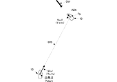
- FIG. 4 is a diagram illustrating an example of controlling the amount of power and the propulsion direction for moving to a fixed point after estimating the direction of the disturbance vector Ddr.
- a velocity vector Mov1 is composed of an azimuth ⁇ p and a velocity Vp, and is a velocity vector for moving from the current position Ps to the fixed point position Pp.
- the velocity vector Mov2 is composed of an azimuth ⁇ d and a velocity Vd, and is a velocity vector for staying at the fixed point position Pp with reference to the fixed point position Pp.
- the hull control unit 24 changes the target direction to be targeted and the target speed to be targeted based on the distance to the fixed point position Pp.
- the hull control unit 24 sets the current position Ps obtained by the positioning unit 22 as the position Pstart, and sets the azimuth heading to the fixed point position Pp as the direction ⁇ p with the position Pstart as a reference.
- the hull control unit 24 sets the maximum settable speed of the ship 10 as the speed Vp.
- the hull control unit 24 sets the direction opposite to the estimated direction of the disturbance vector Ddr as the direction ⁇ d and sets the speed 0 as the speed Vd.
- the hull control unit 24 weights and adds the azimuth ⁇ p and the azimuth ⁇ d to obtain the target azimuth ⁇ x. As shown in the following equation, the hull control unit 24 weights and adds the speed Vp and the speed Vd to obtain the target speed Vx.
- ⁇ x ⁇ p + (1- ⁇ ) ⁇ d
- Vx ⁇ Vp + (1- ⁇ ) Vd
- the coefficient ⁇ is a value greater than 0 and less than or equal to 1, and is obtained based on the distance DIS from the current position Ps to the fixed point position Pp, as shown in the following equation.
- the distance DISi is a distance from the position Pstart to the fixed point position Pp. That is, the hull control unit 24 increases the coefficient ⁇ as the distance DIS is longer, and decreases the coefficient ⁇ as the distance DIS is shorter.
- the hull control unit 24 calculates the target orientation ⁇ x and the target speed Vx so that the ship 10 stays at the fixed point position Pp if the ship 10 is close to the fixed point position Pp. Further, the hull control unit 24 calculates the target azimuth ⁇ x and the target speed Vx so as to go to the fixed point position Pp if the ship 10 is far from the fixed point position Pp.
- the hull control unit 24 generates power amount control information and propulsion direction control information so that the ship 10 navigates at the target direction ⁇ x and the target speed Vx. Specifically, the hull control unit 24 generates propulsion direction control information in which the rudder angle to be taken by the rudder 40 is a value obtained by multiplying the deviation angle ⁇ diff between the target azimuth ⁇ x and the bow azimuth ⁇ s by a predetermined coefficient k1. .
- the heading ⁇ s is acquired by a heading sensor provided in the sensor 23.
- the hull control unit 24 outputs the speed difference Vdiff obtained by subtracting the speed of the ship 10 from the target speed Vx to the power control unit 26 as power amount control information.
- the power control unit 26 controls the power source 30 as a power amount to be given to the power source 30 by multiplying the speed difference Vdiff by a predetermined coefficient k2. However, the power control unit 26 sets the power amount to 0 when the speed difference Vdiff is a negative value (the target speed Vx is smaller than the speed of the ship 10).
- the speed of the ship 10 is calculated
- the hull control unit 24 outputs power amount control information so that the ship 10 moves toward the disturbance orthogonal line. At this time, the farther the ship 10 is from the disturbance orthogonal line, the higher the target speed Vx. Therefore, the ship 10 may greatly pass (overshoot) the disturbance orthogonal line.
- the power control unit 26 sets an upper limit value of the power amount (for example, the injected fuel amount).
- the power control unit 26 suppresses the power amount F to the upper limit value Fmax. Then, the power control unit 26 adjusts the upper limit value Fmax of the power amount F and keeps the ship 10 near the disturbance orthogonal line.
- the distance Ld ′ is a distance from the position of the ship 10 ′ to the disturbance orthogonal line when the ship 10 ′ existing in ZoneU is farthest from the disturbance orthogonal line.
- the distance Ld ′′ is a distance from the position of the ship 10 ′′ to the disturbance orthogonal line when the ship 10 ′′ existing in ZoneD is farthest from the disturbance orthogonal line.
- the power control unit 26 adjusts the upper limit value Fmax of the power amount F based on the distance Ld ′ or the distance Ld ′′. For example, when the distance Ld ′ is longer than the predetermined distance Ldth, the power control unit 26 decreases the upper limit value Fmax of the power amount F by the adjustment amount ⁇ F. Next, when the distance Ld ′′ is longer than the predetermined distance Ldth, the power control unit 26 further reduces the upper limit value Fmax by the adjustment amount ⁇ F.
- the power control unit 26 increases the upper limit value Fmax of the power amount by the adjustment amount ⁇ F.
- the power control unit 26 further increases the upper limit value Fmax by the adjustment amount ⁇ F.
- the ship 10 prevents a large overshoot by suppressing the speed, and increases the speed when the overshoot becomes small.
- the ship 10 repeatedly increases and decreases the speed, and controls the overshoot distance.
- the ship 10 estimates the disturbance azimuth and performs automatic navigation toward the fixed point position so that the bow azimuth faces the disturbance azimuth at the fixed point position based on the estimated disturbance azimuth.
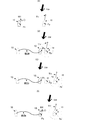
- the ship 10 When the fixed point position Pp is set as shown in FIG. 5 (A), the ship 10 is headed toward the fixed point position Pp as indicated by the white thick arrow 801 while receiving disturbance.
- the hull control unit 24 periodically calculates the distance from the current position Ps of the ship 10 to the fixed point position Pp during automatic navigation. As shown in FIG. 5B, the fixed point position Pp is changed to a fixed point position Pp ′ as shown in FIG. 5C when the distance becomes a predetermined distance R (for example, 10 m) or less.
- the fixed point position Pp ′ may be set manually, or the fixed point setting unit 241 may set it automatically.
- the hull control unit 24 sets the heading azimuth at the fixed point position Pp ′ as the azimuth ⁇ d, but the target direction ⁇ x may be changed when the fixed point position is updated.
- the ship 10 can also use the speed of the ship 10 as a trigger for setting a new fixed point position without using the distance from the current position Ps to the fixed point position Pp.
- the ship 10 performs control such that it remains at the fixed point position Pp. Therefore, the speed of the ship 10 decreases as it approaches the fixed point position Pp. Therefore, the hull control unit 24 sets a new fixed point position Pp ′ using a trigger that the speed of the ship 10 becomes lower than a predetermined threshold.
- the hull control unit 24 periodically obtains the speed using a speed sensor provided in the sensor 23. Then, the hull control unit 24 determines that the speed has decreased because it has approached the fixed point position Pp when the speed has continuously reached a predetermined threshold value or less for a predetermined time, and sets a new fixed point position Pp ′.
- FIG. 6 is a diagram showing a route when the position of the fixed point is sequentially changed.
- the fixed point position Pp (n) is a fixed point position set in order n.
- the route 901 is a trajectory route of the ship 10.
- the ship 10 sets the fixed point position Pp (1) when it is located at the starting point S as shown in FIG. Then, when the ship 10 approaches the fixed point position Pp (1), the fixed point position Pp (2) is set. Similarly to the fixed point position Pp (1) and the fixed point position Pp (2), the fixed point position Pp (3) and the fixed point position Pp (4) are set when approaching the immediately preceding fixed point position Pp.
- the vessel 10 can automatically navigate according to the change of the fixed point position Pp while maintaining the heading azimuth ⁇ s in the azimuth ⁇ d (opposite the disturbance azimuth).
- a new fixed point position Pp ′ is set by using the distance R or speed to the fixed point position Pp as a trigger, but the fixed point position Pp may be changed every predetermined time.
- the fixed point setting unit 241 sets a final arrival point Pd as a point where the user finally wants to reach by automatic navigation.
- the fixed point setting unit 241 sets a target straight line 700 from the current position Ps of the ship 10 to the final arrival point Pd when the final arrival point Pd is set.
- the fixed point setting unit 241 sets a point on the set target straight line 700 and at a predetermined distance L from the current position Ps as the fixed point position Pp.
- the fixed point setting unit 241 exists at a distance L from the current position Ps on the target straight line 700 when approaching a predetermined distance R (however, distance R ⁇ distance L) from the fixed point position Pp.
- a new fixed point position Pp ′ is set at the point to be processed.
- the ship 10 can move in a substantially straight line to the final destination point Pd by automatically setting the fixed point position Pp.
- the new fixed point position Pp ′ may be set to a point separated by the distance L with reference to the fixed point position Pp without using the current position Ps as a reference.
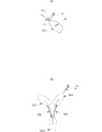
- FIG. 8 is a diagram illustrating setting of a fixed point when a user inputs a route.
- the user inputs the route 600 to the hull control unit 24 as shown in FIG. 8A via the operation unit 25 (for example, through a touch panel). Then, as shown in FIG. 8A, the fixed point setting unit 241 sets a fixed point position Pp at a point away from the current position Ps by a predetermined distance L on the route 600 input by the user.
- the ship 10 automatically navigates as the route 600 by sequentially setting the fixed point position Pp on the route 600 input by the user.
- the fixed point setting unit 241 may store a plurality of automatically navigated routes, display the plurality of stored routes on the operation unit 25 (for example, a display with a touch panel), and allow the user to select a route to be automatically navigated.
- FIG. 9 is a flowchart of movement control during automatic navigation of the ship 10.
- the fixed point position Pp has already been set by the user or by the hull control unit 24. It is assumed that the target orientation ⁇ x and the target speed Vx are also obtained according to the current position Ps by setting the fixed point position Pp.
- the hull control unit 24 acquires the heading azimuth ⁇ s that is the heading from the center of the hull toward the bow with the heading sensor provided in the sensor 23 during automatic navigation (S101).
- the hull control unit 24 calculates a declination ⁇ diff between the bow direction ⁇ s and the target direction ⁇ x. Then, the hull control unit 24 determines whether or not the deviation angle ⁇ diff is smaller than a predetermined angle ⁇ th (S102). If the deflection angle ⁇ diff is smaller than the angle ⁇ th (S102: Yes), the hull control unit 24 proceeds to step S103.
- the hull control unit 24 acquires the current position Ps of the ship 10 when the deflection angle ⁇ diff is smaller than the angle ⁇ th (S102: Yes) (S103).
- the hull control unit 24 calculates the distance from the current position Ps to the fixed point position Pp. Then, the hull control unit 24 determines whether or not the distance is smaller than the predetermined distance S (S104). If the distance is smaller than the distance S (S104: Yes), the hull control unit 24 proceeds to step S105.
- the fixed point setting unit 241 sets a new fixed point position Pp ′ (S105), and generates control information to move to the fixed point position Pp ′ ( S106).
- the hull control unit 24 When the distance from the current position Ps to the fixed point position Pp is equal to or greater than the predetermined distance S (S104: No), the hull control unit 24 performs control toward the fixed point position Pp (S106). That is, in this case, the fixed point setting unit 241 does not change the fixed point position Pp.
- the hull control unit 24 executes the azimuth control for adjusting the bow azimuth ⁇ s when the deflection angle ⁇ diff between the current bow azimuth ⁇ s and the target azimuth ⁇ x is equal to or larger than the angle ⁇ th (S102: No) (S107).
- FIG. 10 is a diagram showing the concept of azimuth control.
- FIG. 10A is a diagram showing an example in which the heading azimuth ⁇ s is significantly different from the target orientation ⁇ x.
- FIG. 10B is a diagram illustrating a route of the ship 10 for adjusting the heading ⁇ s.
- a ship 10 (n) indicates the ship 10 at a predetermined position (n).
- the ship 10 changes the bow direction ⁇ s by moving forward and backward (turning around on the spot) at the current position Ps.
- the heading azimuth ⁇ s of the ship 10 (1) is an azimuth counterclockwise with respect to the target azimuth ⁇ x. That is, the deviation angle ⁇ diff between the target azimuth ⁇ x and the bow azimuth ⁇ s is a negative angle.
- the hull control unit 24 outputs information on the propulsion direction for turning the rudder 40 to the left and information on the amount of power for moving the ship 10 (1) backward. To do.
- the ship 10 moves backward as the adjustment channel 902 makes the negative declination ⁇ diff approach an angle of 0 degrees.
- the deflection angle ⁇ diff is closer to 0 degrees than the deflection angle ⁇ diff in the state of the ship 10 (1).
- the hull control part 24 outputs the information of the propulsion direction which turns the rudder 40 to the right, and the information of the motive power which advances the ship 10 (2).
- the ship 10 (2) moves forward while making the negative declination angle ⁇ diff closer to 0 degrees as in the adjustment channel 903.
- the deflection angle ⁇ diff is almost zero. That is, the heading azimuth ⁇ s coincides with the target direction ⁇ x as shown in the ship 10 (3).
- the hull control unit 24 moves the boat 10 backward with information on the propulsion direction for turning the rudder 40 to the right when the declination ⁇ diff is a positive angle and the absolute value of the declination ⁇ diff is equal to or greater than a predetermined threshold. Output power information. Next, the hull control unit 24 outputs information on the propulsion direction for turning the rudder 40 to the left and information on the amount of power for moving the ship 10 forward.
- the hull control unit 24 performs the backward control first, but may perform the forward control.
- the hull control unit 24 (fixed point setting unit 241) performs the above steps S101 to S107 periodically to automatically navigate.
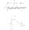
- FIG. 11 is a diagram illustrating a concept of movement control of the ship 10 according to the application example 1.
- the azimuth ⁇ d is set to face the disturbance azimuth, but the application example 1 shows an example of facing the wind direction and flowing in the tidal current.
- FIG. 11 (A) is a diagram showing an example in which the ship 10 moves along the tidal current with the bow facing the direction of the wind.
- a tidal current vector Tid is a velocity vector indicating a tidal current velocity and direction.
- the wind vector Wnd is a velocity vector indicating the direction and magnitude of the wind.
- a fisherman may perform drift fishing that moves a ship along a tidal current so as to pass a predetermined point (for example, a reef or a set). The fisherman manipulates the boat so that the bow stands upwind so that the bow does not flow downwind.
- a predetermined point for example, a reef or a set.
- the hull control unit 24 of the ship 10 sets the direction ⁇ d of the velocity vector Mov2 illustrated in FIG. 4 so as to face the direction of the wind vector Wnd.
- the direction of the wind vector Wnd is detected by the wind direction sensor of the sensor 23.
- the fixed point setting unit 241 sets a target straight line 701 that passes through the current position Ps and is parallel to the direction of the tidal vector Tid, as shown in FIG. 11A. Then, the fixed point setting unit 241 sets a fixed point position Pp on the target straight line 701 that is a predetermined distance away from the current position Ps on the downstream side of the tidal current.
- the direction of the tidal vector Tid is obtained by a tidal meter provided in the sensor 23.
- the ship 10 automatically navigates along the fixed point position Pp that is sequentially changed to the direction of the tidal vector Tid, with the bow direction ⁇ s facing the direction of the wind vector Wnd.
- the ship 10 can perform drift fishing without a mechanism such as a spanker for raising the bow to the windward or a side thruster for moving in parallel.
- the ship 10 may set the direction ⁇ d as the direction of the tidal vector Tid and set the target straight line 701 to be parallel to the direction of the wind vector Wnd.
- FIG. 13 is a diagram illustrating a concept of movement control of the ship 10 according to the application example 2.
- the direction ⁇ d is set to face the wind direction, the tidal current direction, or a combination thereof, but may be set to another direction.
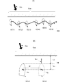
- FIG. 12 (A) is a diagram showing an example in which the ship 10 automatically sails along the quay Qua.
- FIG. 12B is a diagram illustrating setting of the fixed point position Pp and the azimuth ⁇ d of the ship 10 according to the application example 2.
- the fisherman may operate the ship to move along the quay with the bow facing the quay to search for the target fish.
- the fixed point setting unit 241 of the ship 10 sets the fixed point position Pp based on the distance D from the bow of the ship 10 to the quay Qua as shown in FIG.
- the fixed point setting unit 241 sets the length from the bow to the center of the hull as the length Ls, and is separated from the quay Qua by the total distance N of the distance D and the length Ls, A point that is a distance M away from the current fixed point position Pp in a direction parallel to the quay is set as the fixed point position Pp.
- the distance D and the length Ls are input from the user to the operation unit 25, for example. Further, the user inputs the azimuth ⁇ d to the operation unit 25 so as to be orthogonal to the quay Qua. Then, the hull control unit 24 performs movement control toward the fixed point position Pp.
- the ship 10 can automatically navigate along the quay Qua only by setting the fixed point position Pp and the direction ⁇ d.
- the hull control unit 24 can also control the ship 10 so as to measure the distance D from the bow to the quay Qua using a chart stored in advance and a GPS or an ultrasonic sensor during automatic navigation. In this case, when the distance D from the bow to the quay Qua is equal to or less than a predetermined distance, the hull control unit 24 moves forward or backward and leaves the quay Qua.
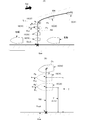
- FIG. 13 is a diagram illustrating a concept of movement control of the ship 10 according to the application example 3.
- FIG. 13A is a diagram showing an example in which the ship 10 arrives at the arrival point Dock of the quay Qua.
- FIG. 13B is a diagram illustrating the setting of the fixed point position Pp and the target orientation ⁇ x of the ship 10 according to the application example 3.
- the ship 10 according to the application example 3 automatically navigates so as to gradually approach the quay while keeping the heading ⁇ s parallel to the quay Qua.
- the user when the user manually maneuvers to the position shown in the ship 10 (33) as shown in the route 904 shown in FIG. 13A, the user inputs a docking point Dock to be docked into the operation unit 25 on the chart. Further, the user inputs the azimuth ⁇ d to the operation unit 25 so as to be parallel to the quay Qua.
- the fixed point setting unit 241 obtains the current position Ps using the positioning unit 22 as shown in FIG. Then, the fixed point setting unit 241 sets a target straight line 702 that connects the current position Ps and the landing point Dock.
- the fixed point setting unit 241 sets a fixed point position Pp on the target straight line 702.
- the fixed point position Pp is set at a point on the target straight line 701 that is a predetermined distance T away from the landing point Dock.
- the hull control unit 24 outputs control information to the power source 30 and the rudder control unit 27 so as to go to the fixed point position Pp.
- the fixed point setting unit 241 sets a new fixed point position Pp ′ when the current position Ps approaches the fixed point position Pp to a predetermined distance U.
- the new fixed point position Pp ′ is set at a point on the target straight line 702 that is a predetermined distance T ′ away from the landing point Dock.
- the distance T ′ is 0.7 times the distance T, for example.
- the distance U ′ serving as a trigger for setting a new fixed point position Pp ′ is set to a value that is, for example, 0.7 times the distance U.
- the ship 10 does not rapidly bring the fixed point position Pp close to the quay Qua. That is, the ship 10 can gradually approach the quay Qua.
- the ship 10 can further approach the quay Qua more gently.
- a ship is shown as an example of a moving body.
- the configuration and processing of can be applied.
- each functional unit is an example of hardware.
- the positioning unit 22, the hull control unit 24, the power control unit 26, and the rudder control unit 27 can be realized by software. That is, the above-described processing can be realized by programming the processing of these functional units and storing them in a storage medium, and reading out and executing the hull control program by an arithmetic unit (computer or the like).
Landscapes
- Chemical & Material Sciences (AREA)
- Engineering & Computer Science (AREA)
- Combustion & Propulsion (AREA)
- Mechanical Engineering (AREA)
- Ocean & Marine Engineering (AREA)
- Control Of Position, Course, Altitude, Or Attitude Of Moving Bodies (AREA)
- Navigation (AREA)
Abstract
Description

Vx = αVp + (1-α)Vd
ただし、係数αは、0より大きく1以下の値であり、以下の式に示すように、現在位置Psから定点位置Ppまでの距離DISに基づいて求められる。
ただし、距離DISiは、位置Pstartから定点位置Ppまでの距離である。すなわち、船体制御部24は、距離DISが長ければ長いほど係数αを大きくし、距離DISが短ければ短いほど係数αを小さくする。
20…船体制御装置
21…アンテナ
22…測位部
23…センサ
24…船体制御部
25…操作部
26…動力制御部
27…舵制御部
30…動力源
31…プロペラ
40…舵
240…外乱方位推定部
241…定点設定部
Claims (15)
- 特定の一方向に移動体を推進させる推進力発生部と、該推進力により移動する方向を調整する移動方向調整部とを前記移動体に備える移動体制御装置であって、
前記移動体を移動させる外乱の方向を推定する外乱方向推定手段と、
前記移動体の向いている方向を検出する移動体方向検出手段と、
前記移動体の位置を検出する位置検出手段と、
前記移動体が留まるべき位置である定点位置を設定する位置設定手段と、
前記移動体方向検出手段で検出した移動体の向いている方向が前記外乱方向推定手段で推定した外乱の方向に対向し、かつ前記位置設定手段で設定した定点位置に前記移動体が留まるように、前記推進力発生部および前記移動方向調整部を制御する制御手段と、
前記定点位置を逐次変更する変更手段と、
を備える移動体制御装置。 - 請求項1に記載の移動体制御装置であって、
前記変更手段は、前記位置検出手段が検出した移動体の位置と、前記定点位置との距離が第1の所定の距離未満の場合、前記定点位置を変更する
移動体制御装置。 - 請求項1に記載の移動体制御装置であって、
前記移動体の移動する速度を検出する速度検出手段を備え、
前記変更手段は、前記速度検出手段が検出した速度が所定の速度未満の場合、前記定点位置を変更する
移動体制御装置。 - 請求項1に記載の移動体制御装置であって、
前記変更手段は、所定時間毎に前記定点位置を変更する
移動体制御装置。 - 請求項1乃至請求項4のいずれかに記載の移動体制御装置であって、
前記変更手段は、前記移動体が移動すべき目標経路を受け付け、前記目標経路上に前記定点位置を変更する
移動体制御装置。 - 請求項1乃至請求項5のいずれかに記載の移動体制御装置であって、
前記外乱は、前記移動体を移動させる風及び潮流であり、
前記制御手段は、前記移動体方向検出手段で検出した移動体の向いている方向が風の方向に対向するように前記推進力発生部および前記移動方向調整部を制御する
移動体制御装置。 - 請求項1乃至請求項5のいずれかに記載の移動体制御装置であって、
前記外乱は、前記移動体を移動させる風及び潮流であり、
前記制御手段は、前記移動体方向検出手段で検出した移動体の向いている方向が潮流の方向に対向するように前記推進力発生部および前記移動方向調整部を制御する
移動体制御装置。 - 請求項1乃至請求項7のいずれかに記載の移動体制御装置であって、
前記制御手段は、前記移動体の移動の目標となる目標物を受け付け、前記目標物の向きに応じて前記移動体方向検出手段で検出した移動体の向いている方向を制御する
移動体制御装置。 - 請求項8に記載の移動体制御装置であって、
前記制御手段は、前記移動体の向いている方向が前記目標物の存在する方向となるように制御する
移動体制御装置。 - 請求項9に記載の移動体制御装置であって、
前記変更手段は、前記目標物の存在する方向と直交する方向に位置し、かつ前記目標物との距離が第2の所定の距離に位置する位置に前記定点位置を変更する
移動体制御装置。 - 請求項8に記載の移動体制御装置であって、
前記制御手段は、前記移動体の向いている方向が前記目標物の存在する方向と直交するように制御する
移動体制御装置。 - 請求項11に記載の移動体制御装置であって、
前記変更手段は、前記目標物の存在する方向に位置し、かつ前記目標物との距離が第3の所定の距離に位置する位置に前記定点位置を変更する
移動体制御装置。 - 請求項1乃至請求項12のいずれかに記載の移動体制御装置であって、
前記制御手段は、前記移動体方向検出手段が検出した移動体の向いている方向と前記外乱方向推定手段が推定した外乱の方向との偏角が所定の角度以上となった場合、前記移動体の向いている方向を前記外乱の方向に対向させる制御のみを行う
移動体制御装置。 - 特定の一方向に移動体を推進させる推進力発生部と、該推進力により移動する方向を調整する移動方向調整部とを備えた前記移動体を制御する移動体制御方法であって、
前記移動体を移動させる外乱の方向を推定する外乱方向推定ステップと、
前記移動体の向いている方向を検出する移動体方向検出ステップと、
前記移動体の位置を検出する位置検出ステップと、
前記移動体が留まるべき位置である定点位置を設定する位置設定ステップと、
前記移動体方向検出ステップで検出した移動体の向いている方向が前記外乱方向推定ステップで推定した外乱の方向に対向し、かつ前記位置設定ステップで設定した定点位置に前記移動体が留まるように、前記推進力発生部および前記移動方向調整部を制御する制御ステップと、
前記定点位置を逐次変更する変更ステップと、
からなる移動体制御方法。 - 特定の一方向に移動体を推進させる推進力発生部と、該推進力により移動する方向を調整する移動方向調整部とを前記移動体を制御する移動体制御装置に実行される移動体制御プログラムであって、
前記移動体を移動させる外乱の方向を推定する外乱方向推定ステップと、
前記移動体の向いている方向を検出する移動体方向検出ステップと、
前記移動体の位置を検出する位置検出ステップと、
前記移動体が留まるべき位置である定点位置を設定する位置設定ステップと、
前記移動体方向検出ステップで検出した移動体の向いている方向が前記外乱方向推定ステップで推定した外乱の方向に対向し、かつ前記位置設定ステップで設定した定点位置に前記移動体が留まるように、前記推進力発生部および前記移動方向調整部を制御する制御ステップと、
前記定点位置を逐次変更する変更ステップと、
を実行する移動体制御プログラム。
Priority Applications (2)
| Application Number | Priority Date | Filing Date | Title |
|---|---|---|---|
| JP2016566051A JP6821437B2 (ja) | 2014-12-22 | 2015-11-26 | 移動体制御装置、移動体制御方法、および移動体制御プログラム |
| US15/538,602 US10183733B2 (en) | 2014-12-22 | 2015-11-26 | Program, method and device for controlling movable body |
Applications Claiming Priority (2)
| Application Number | Priority Date | Filing Date | Title |
|---|---|---|---|
| JP2014258201 | 2014-12-22 | ||
| JP2014-258201 | 2014-12-22 |
Publications (1)
| Publication Number | Publication Date |
|---|---|
| WO2016104030A1 true WO2016104030A1 (ja) | 2016-06-30 |
Family
ID=56150062
Family Applications (1)
| Application Number | Title | Priority Date | Filing Date |
|---|---|---|---|
| PCT/JP2015/083151 Ceased WO2016104030A1 (ja) | 2014-12-22 | 2015-11-26 | 移動体制御装置、移動体制御方法、および移動体制御プログラム |
Country Status (3)
| Country | Link |
|---|---|
| US (1) | US10183733B2 (ja) |
| JP (1) | JP6821437B2 (ja) |
| WO (1) | WO2016104030A1 (ja) |
Cited By (9)
| Publication number | Priority date | Publication date | Assignee | Title |
|---|---|---|---|---|
| EP3486742A1 (en) * | 2017-11-20 | 2019-05-22 | Brunswick Corporation | System and method for controlling a position of a marine vessel near an object |
| JP2021011158A (ja) * | 2019-07-05 | 2021-02-04 | 古野電気株式会社 | 船体制御装置、船体制御方法、および、船体制御プログラム |
| KR20210097041A (ko) * | 2020-01-28 | 2021-08-06 | 나부테스코 가부시키가이샤 | 선박 |
| JP2021181301A (ja) * | 2020-05-15 | 2021-11-25 | 国立研究開発法人 海上・港湾・航空技術研究所 | 船舶の自動誘導方法、船舶の自動誘導プログラム、船舶の自動誘導システム、及び船舶 |
| US11643180B2 (en) | 2019-09-13 | 2023-05-09 | Furuno Electric Company Limited | Ship speed control device, ship speed controlling method, and ship speed control program |
| US11866142B2 (en) | 2019-09-13 | 2024-01-09 | Furuno Electric Company Limited | Hull control device, hull controlling method, and hull control program |
| US11866141B2 (en) | 2019-06-27 | 2024-01-09 | Furuno Electric Company Limited | Device, method, and program for controlling ship body |
| US11873067B2 (en) | 2019-06-28 | 2024-01-16 | Furuno Electric Company Limited | Device, method, and program for controlling ship body |
| WO2025094973A1 (ja) * | 2023-10-30 | 2025-05-08 | 日本発條株式会社 | 船舶制御装置、船舶、船舶制御方法及びプログラム |
Families Citing this family (24)
| Publication number | Priority date | Publication date | Assignee | Title |
|---|---|---|---|---|
| US11899465B2 (en) * | 2014-12-31 | 2024-02-13 | FLIR Belgium BVBA | Autonomous and assisted docking systems and methods |
| US10640190B1 (en) | 2016-03-01 | 2020-05-05 | Brunswick Corporation | System and method for controlling course of a marine vessel |
| US10198005B2 (en) | 2016-03-01 | 2019-02-05 | Brunswick Corporation | Station keeping and waypoint tracking methods |
| US10322787B2 (en) * | 2016-03-01 | 2019-06-18 | Brunswick Corporation | Marine vessel station keeping systems and methods |
| US9952595B2 (en) | 2016-03-01 | 2018-04-24 | Brunswick Corporation | Vessel maneuvering methods and systems |
| US10259555B2 (en) | 2016-08-25 | 2019-04-16 | Brunswick Corporation | Methods for controlling movement of a marine vessel near an object |
| WO2018100750A1 (ja) * | 2016-12-02 | 2018-06-07 | ヤマハ発動機株式会社 | 小型船舶 |
| US10671073B2 (en) * | 2017-02-15 | 2020-06-02 | Brunswick Corporation | Station keeping system and method |
| US12205473B2 (en) * | 2017-06-16 | 2025-01-21 | FLIR Belgium BVBA | Collision avoidance systems and methods |
| US11733699B2 (en) * | 2017-06-16 | 2023-08-22 | FLIR Belgium BVBA | Ultrasonic perimeter ranging sensor systems and methods |
| US10324468B2 (en) | 2017-11-20 | 2019-06-18 | Brunswick Corporation | System and method for controlling a position of a marine vessel near an object |
| US10884416B2 (en) | 2017-12-11 | 2021-01-05 | Garmin Switzerland Gmbh | Foot pedal device for controlling a trolling motor |
| US10845812B2 (en) | 2018-05-22 | 2020-11-24 | Brunswick Corporation | Methods for controlling movement of a marine vessel near an object |
| US10633072B1 (en) | 2018-07-05 | 2020-04-28 | Brunswick Corporation | Methods for positioning marine vessels |
| US11530022B1 (en) | 2018-07-10 | 2022-12-20 | Brunswick Corporation | Method for controlling heading of a marine vessel |
| US11858609B2 (en) | 2020-05-27 | 2024-01-02 | Garmin Switzerland Gmbh | Foot controller system for marine motor |
| US11531341B2 (en) | 2020-06-12 | 2022-12-20 | Garmin Switzerland Gmbh | Marine autopilot system |
| CN113110531B (zh) * | 2021-04-19 | 2021-11-12 | 飞马滨(青岛)智能科技有限公司 | 一种水下机器人与待洗船只的自动贴壁方法 |
| JP2022180886A (ja) * | 2021-05-25 | 2022-12-07 | ヤマハ発動機株式会社 | 船舶推進制御システム及び船舶 |
| JP2023068836A (ja) * | 2021-11-04 | 2023-05-18 | ヤマハ発動機株式会社 | 船舶推進システムおよび船舶 |
| JP2023092070A (ja) * | 2021-12-21 | 2023-07-03 | ヤマハ発動機株式会社 | 船舶推進制御システム及び船舶 |
| JP2023135073A (ja) * | 2022-03-15 | 2023-09-28 | ヤマハ発動機株式会社 | 操船システムおよびそれを備える船舶 |
| JP2025025667A (ja) * | 2023-08-10 | 2025-02-21 | ヤマハ発動機株式会社 | 船舶推進システムおよび船舶 |
| JP2026002253A (ja) * | 2024-06-21 | 2026-01-08 | ヤマハ発動機株式会社 | 船舶の制御装置および船舶 |
Citations (5)
| Publication number | Priority date | Publication date | Assignee | Title |
|---|---|---|---|---|
| US5386368A (en) * | 1993-12-13 | 1995-01-31 | Johnson Fishing, Inc. | Apparatus for maintaining a boat in a fixed position |
| JP2013151241A (ja) * | 2012-01-25 | 2013-08-08 | Marol Ltd | 船体用制御装置、船体用制御プログラムおよび船体の制御方法 |
| JP2014024421A (ja) * | 2012-07-26 | 2014-02-06 | Furuno Electric Co Ltd | 移動体制御装置、船体制御装置、船舶、移動体制御方法、および移動体制御プログラム |
| WO2014065147A1 (ja) * | 2012-10-22 | 2014-05-01 | 古野電気株式会社 | 船体制御方法および船体制御装置 |
| WO2014148168A1 (ja) * | 2013-03-22 | 2014-09-25 | ヤンマー株式会社 | 操船システム及びそれを備える船舶 |
Family Cites Families (4)
| Publication number | Priority date | Publication date | Assignee | Title |
|---|---|---|---|---|
| JP2002087389A (ja) | 2000-09-12 | 2002-03-27 | Ishigaki Co Ltd | 船舶のサイドスラスター装置 |
| JP2002178990A (ja) * | 2000-12-14 | 2002-06-26 | Yokogawa Denshikiki Co Ltd | 自動航行装置 |
| JP5860248B2 (ja) | 2011-04-25 | 2016-02-16 | 株式会社ワイズギア | スパンカー |
| US9003986B2 (en) * | 2013-03-14 | 2015-04-14 | Saildrone, Inc. | Autonomous sailing vessel |
-
2015
- 2015-11-26 US US15/538,602 patent/US10183733B2/en active Active
- 2015-11-26 JP JP2016566051A patent/JP6821437B2/ja not_active Expired - Fee Related
- 2015-11-26 WO PCT/JP2015/083151 patent/WO2016104030A1/ja not_active Ceased
Patent Citations (5)
| Publication number | Priority date | Publication date | Assignee | Title |
|---|---|---|---|---|
| US5386368A (en) * | 1993-12-13 | 1995-01-31 | Johnson Fishing, Inc. | Apparatus for maintaining a boat in a fixed position |
| JP2013151241A (ja) * | 2012-01-25 | 2013-08-08 | Marol Ltd | 船体用制御装置、船体用制御プログラムおよび船体の制御方法 |
| JP2014024421A (ja) * | 2012-07-26 | 2014-02-06 | Furuno Electric Co Ltd | 移動体制御装置、船体制御装置、船舶、移動体制御方法、および移動体制御プログラム |
| WO2014065147A1 (ja) * | 2012-10-22 | 2014-05-01 | 古野電気株式会社 | 船体制御方法および船体制御装置 |
| WO2014148168A1 (ja) * | 2013-03-22 | 2014-09-25 | ヤンマー株式会社 | 操船システム及びそれを備える船舶 |
Cited By (14)
| Publication number | Priority date | Publication date | Assignee | Title |
|---|---|---|---|---|
| EP3486742A1 (en) * | 2017-11-20 | 2019-05-22 | Brunswick Corporation | System and method for controlling a position of a marine vessel near an object |
| US10429845B2 (en) | 2017-11-20 | 2019-10-01 | Brunswick Corporation | System and method for controlling a position of a marine vessel near an object |
| US11866141B2 (en) | 2019-06-27 | 2024-01-09 | Furuno Electric Company Limited | Device, method, and program for controlling ship body |
| US11873067B2 (en) | 2019-06-28 | 2024-01-16 | Furuno Electric Company Limited | Device, method, and program for controlling ship body |
| JP7263158B2 (ja) | 2019-07-05 | 2023-04-24 | 古野電気株式会社 | 船体制御装置、船体制御方法、および、船体制御プログラム |
| JP2021011158A (ja) * | 2019-07-05 | 2021-02-04 | 古野電気株式会社 | 船体制御装置、船体制御方法、および、船体制御プログラム |
| US11884371B2 (en) | 2019-07-05 | 2024-01-30 | Furuno Electric Company Limited | Device, method, and program for controlling ship body |
| US11643180B2 (en) | 2019-09-13 | 2023-05-09 | Furuno Electric Company Limited | Ship speed control device, ship speed controlling method, and ship speed control program |
| US11866142B2 (en) | 2019-09-13 | 2024-01-09 | Furuno Electric Company Limited | Hull control device, hull controlling method, and hull control program |
| KR102515003B1 (ko) * | 2020-01-28 | 2023-03-30 | 나부테스코 가부시키가이샤 | 선박 |
| KR20210097041A (ko) * | 2020-01-28 | 2021-08-06 | 나부테스코 가부시키가이샤 | 선박 |
| JP2021181301A (ja) * | 2020-05-15 | 2021-11-25 | 国立研究開発法人 海上・港湾・航空技術研究所 | 船舶の自動誘導方法、船舶の自動誘導プログラム、船舶の自動誘導システム、及び船舶 |
| JP7756895B2 (ja) | 2020-05-15 | 2025-10-21 | 国立研究開発法人 海上・港湾・航空技術研究所 | 船舶の自動誘導方法、船舶の自動誘導プログラム、船舶の自動誘導システム、及び船舶 |
| WO2025094973A1 (ja) * | 2023-10-30 | 2025-05-08 | 日本発條株式会社 | 船舶制御装置、船舶、船舶制御方法及びプログラム |
Also Published As
| Publication number | Publication date |
|---|---|
| JP6821437B2 (ja) | 2021-01-27 |
| US20180015994A1 (en) | 2018-01-18 |
| US10183733B2 (en) | 2019-01-22 |
| JPWO2016104030A1 (ja) | 2017-09-28 |
Similar Documents
| Publication | Publication Date | Title |
|---|---|---|
| JP6821437B2 (ja) | 移動体制御装置、移動体制御方法、および移動体制御プログラム | |
| JPWO2016104030A6 (ja) | 移動体制御装置、移動体制御方法、および移動体制御プログラム | |
| JP6370924B2 (ja) | 移動体制御装置、移動体制御方法、および移動体制御プログラム | |
| EP3889030B1 (en) | ROUTE GENERATION DEVICE | |
| JP5957695B2 (ja) | 移動体制御装置、船体制御装置、船舶、移動体制御方法、および移動体制御プログラム | |
| JP7417538B2 (ja) | 制御目標生成装置及び操船制御装置 | |
| KR20230011310A (ko) | 선박의 자동 유도 방법, 선박의 자동 유도 프로그램, 선박의 자동 유도 시스템 및 선박 | |
| JP6278567B2 (ja) | 船体制御方法および船体制御装置 | |
| EP3170735B1 (en) | Boat maneuvering control method for boat and boat maneuvering control system for boat | |
| JP2004042884A (ja) | 移動体の操縦方法及び装置 | |
| US20200062366A1 (en) | Ship maneuvering system, ship, and ship maneuvering method | |
| JP5956233B2 (ja) | 航路保持制御装置及び船舶 | |
| CN109166355B (zh) | 一种船舶航道航行时的变速避让系统 | |
| JP6686249B2 (ja) | 船舶の自動操縦システム、船舶、及び船舶の自動操縦方法 | |
| JP2010173589A (ja) | 船舶用位置保持制御装置 | |
| WO2023153015A1 (ja) | 自動着桟機能を有する一軸二舵船 | |
| JP2001287697A (ja) | 船舶の航路保持制御装置及び方法 | |
| JP4213518B2 (ja) | 移動体の制御方法及び制御装置 | |
| JP6191984B2 (ja) | 船舶の操舵方法及び船舶の自動操舵装置 | |
| CN117311354B (zh) | 一种基于精确任务导向的港作船自主路径规划及靠泊方法 | |
| JP3999976B2 (ja) | 操船方法及び装置 | |
| JP6450595B2 (ja) | 移動体制御装置、移動体制御方法、および移動体制御プログラム | |
| CN111651943A (zh) | 一种船舶运动控制方法、终端设备及存储介质 | |
| Sliwka et al. | Sailing without wind sensor and other hardware and software innovations | |
| JP7448415B2 (ja) | 燃料制御装置、及び舵制御装置 |
Legal Events
| Date | Code | Title | Description |
|---|---|---|---|
| 121 | Ep: the epo has been informed by wipo that ep was designated in this application |
Ref document number: 15872599 Country of ref document: EP Kind code of ref document: A1 |
|
| ENP | Entry into the national phase |
Ref document number: 2016566051 Country of ref document: JP Kind code of ref document: A |
|
| WWE | Wipo information: entry into national phase |
Ref document number: 15538602 Country of ref document: US |
|
| NENP | Non-entry into the national phase |
Ref country code: DE |
|
| 122 | Ep: pct application non-entry in european phase |
Ref document number: 15872599 Country of ref document: EP Kind code of ref document: A1 |